


PICOWATT
Veromiehentie 14
FI-01510 VANTAA, Finland
phone 358 50 3375192
Internet: www.picowatt.
e-mail: reijo.voutilainen@picowatt.
AVS47-Serial/USB-W CONVERTER
For Interfacing the AVS-47B with Computers
User Guide

Page 2
Revised: 2018-06-04 AVS47_serial_usb_w_userguide_1r3.indd
User
Guide 1R3
For Interfacing the AVS-47B with Computers
AVS47-Serial/USB-W CONVERTER
(for use with rmware version avs47_serial_usb_1r3.ino)
CONTENTS
WARRANTY 3
BACKGROUND 4
USB-Picobus 4
GPIB-Picobus 4
AVS47-Serial/USB-W 4
CONNECTING THE AVS47-Serial/USB-W 5
STARTING THE AVS47-Serial/USB-W 6
Resetting the AVS47-Serial/USB-W 6
RS232 Format 6
COMMANDS AND COMMAND LINES 7
Responses 7
Send/Receive Serial tool 9
FIRST COMMANDS AND QUERIES 10
HARDWARE COMMANDS 10
MEASUREMENT AND READOUT
COMMANDS/QUERIES 11
OTHER COMMANDS AND QUERIES 14
COMMANDS FOR THE TS-530A
TEMPERATURE CONTROLLER 16
CABLE SPECIFICATIONS 18
Picobus Cable (PB25P15P6W5M) 18
Serial Cable (RS9P9S3W1.5M) 18
RE-PROGRAMMING THE AVS47-Serial/USB-W 19
AVS47-Serial/USB-W TROUBLE SHOOTING IDEAS 19
DECLARATION OF CONFORMITY 22
INDEX 23
REVISION HISTORY 25

Page 3
Revised: 2018-06-04 AVS47_serial_usb_w_userguide_1r3.indd
User
Guide 1R3
For Interfacing the AVS-47B with Computers
AVS47-Serial/USB-W CONVERTER
WARRANTY
Picowatt warrants the AVS47-Serial/USB-W
hardware to be free from defects in materials and
workmanship. Our liability under this warranty is
limited to repairing or replacing any instrument or
part thereof which, within three (3) years after the
shipment to the original purchaser, proves defective.
This warranty is void if the instrument has not been
used according to the instruction manual, or if it has
been used under exceptional environmental conditions.
In need of warranty repair, the instrument must
be returned to Picowatt, prepaid , and with a detailed
description of the fault or malfunction following the
instrument.
The name, address and e-mail address of a person
who is able to give supplementary information should be
included whenever possible. If the repair was covered
by warranty, Picowatt will return the instrument on
our cost using an economical shipping method.
If no fault is found, or if there is a strong indication
that the warranty is void, the purchaser is charged for
the return freight and costs in addition to the repair. It
is recommended that Picowatt be contacted prior to
shipment. We can possibly give instructions for addi-
tional tests or simple component replacements so that
unnecessary shipments may be avoided.
The rmware must not be considered a com-
mercial product. It is given as is, for free, without
any kind of warranties or liability. The program and
this user guide may contain errors, and we would be
glad to get feedback, corrections and suggestions for
improvements.
Important: The AVS-47B uses +/- 5 Volt levels for data communications in its standard conguration, whereas the AVS47-Serial/USB-W
can be damaged by applying negative voltages to its 15-pin connector.
Therefore, short circuit piece JP204 MUST BE CHANGED to
position JP203 on circuit board “E” (the board with the power supply
unit) before connecting the AVS-47B and the converter together. In
case of any uncertainty, please contact factory.
If the AVS-47B is interfaced with model AVS47-IB GPIB box, or directly with a PC computer using its Com port or via a USB-232 adapter, this jumper shall be returned to JP204.
RV-Elektroniikka Oy Picowatt
Veromiehentie 14
FI-01510 VANTAA
FINLAND
telephone +358 50 337 5192
email: reijo.voutilainen@picowatt.

Page 4
Revised: 2018-06-04 AVS47_serial_usb_w_userguide_1r3.indd
User
Guide 1R3
For Interfacing the AVS-47B with Computers
AVS47-Serial/USB-W CONVERTER
BACKGROUND
The AVS47-Serial/USB-W is an external protocol
converter that creates an galvanically isolated RS232
interface for the model AVS-47B AC Resistance
Bridge. Until now, Picowatt have offered two possibilities for interfacing the AVS-47B with computers:
The direct Picobus interface and the Model AVS47-
IB external GPIB (IEEE-488) interface unit. Both al-
ternatives have limitations with respect to computer
type, operating system and programming language.
The AVS47-Serial/USB-W removes many of these
limitations at a low cost, offering new possibilities
for computer interfacing. A short comparison of the
three available interfacing solutions follows.
Some commands are for the TS-530A Temperature Controller. This product has been discontinued,
and those features are only for the existing instruments.
USB-Picobus
Picobus is a proprietary synchronous, serial pro-
tocol that is based on two coming and two leaving
signal lines. Suitable four lines are provided by the
hardware handshake outputs and inputs of traditional
Com: ports of PC-type computers. The asynchronous TXD and RXD signals of the RS232 interface
are not used by Picobus. Today’s computers seldom
have physical Com: ports, but a virtual Com: port
can be created by a USB-232 converter.
Unfortunately, low-level Picobus communica-
tion is complicated, as it requires computer program
to write and read states of independent bits of some
hardware registers. In order to make programs portable between different platforms, operating systems
do not favour direct hardware access. For this reason, we offer driving programs (USB-Picobus), but
only for a Windows-PC running LabView2012 or
higher (base version or better).
This has been a serious limitation that excludes
Mac computers and programming languages other
than LabView. The great advantages of Picobus are,
that the protocol is almost bullet-proof, it has low
EMI noise, and for customers with a suitable computer environment, it is completely free with the
exception of a possibly needed USB-232 converter.
GPIB-Picobus (OBSOLETE!)
This interfacing solution is based on an external converter, AVS47-IB, between IEEE-488 and Picobus
protocols.
This very powerful converter offers automatic
scanning of sensors, buffering of data and many
macro commands. The box is connected to - but gal-
vanically isolated from - the AVS-47B via Picobus
and to the computer via GPIB (therefore the name of
this option is GPIB-Picobus). It has its own mains
power supply and it can be located far from the cry-
ostat in order to minimize electromagnetic or ground
current problems that the GPIB line may cause. The
box can be used with computers having an GPIB
controller and suitable software for GPIB communications. It is highly compatible with the IEEE-488.2
standard with its mnemonic and common com-
mands and error reporting. We offer a versatile free
LabView Driver that was written for LV7.1 and can
still be used with today’s LabView versions. For the
most noise-critical applications, an optical bre link
to the bridge is available (AVS47IB-PICOLINK).
The GPIB-Picobus had a much wider range of
applications than USB-Picobus, e.g. it can be interfaced also with Mac and Linux computers. However, for customers that do not already use GPIB, the
cost of this alternative is signicant.
AVS47-Serial/USB-W
The AVS47-Serial/USB-W is also an external proto-
col converter box that is connected to the resistance
bridge via galvanically isolated Picobus. It can be
connected to the computer’s Com: port using a one-
The AVS47-IB is a protocol converter between GPIB
(IEE-488) and Picobus. It is the heart of the “GPIBPicobus” interface.

Page 5
Revised: 2018-06-04 AVS47_serial_usb_w_userguide_1r3.indd
User
Guide 1R3
For Interfacing the AVS-47B with Computers
AVS47-Serial/USB-W CONVERTER
to-one cable with 9-pin connectors. More typically, it
is connected to a virtual RS232 port using a USB-
232 converter which enables RS232 communications
between the computer and the box. The important
difference between USB-Picobus and AVS47-Serial/
USB-W is that the former uses the proprietary synchronous Picobus protocol and the latter is based on
asynchronous RS232.
RS232 is a very old protocol which has disappeared from many instruments because of its low
speed and poorly standardized software behaviour.
However, asynchronous serial communications is far
from dead: Most operating systems, like Windows,
Linux and Mac OS, and most common programming
languages, like C/C++, Python, versions of Basic
etc., LabView and Matlab, support it. The speed is
not an issue with slow instruments, like the AVS-
47B, which produce only tiny amounts of data. The
AVS47-Serial/USB-W expands computer-interfacing
of the AVS-47B beyond a Windows-PC and LabView to almost any application and platform where
RS232 communications is supported.
Commands and queries to the AVS47-Serial/
USB-W are simple and mnemonic, like “RAN3” for
the 200Ω range. Communications is based on the
most common default format without handshaking.
Therefore many low-cost USB-232 converters are
likely to perform well in this application.
The AVS47-Serial/USB-W is based on the very
popular Arduino Mega2560 unit.
AVS47-Serial/USB-W Unit measures 130x105x60
mm and gets power from the +12V Mains Adapter.
CONNECTING THE AVS47-Serial/USBW
The AVS47-Serial/USB-W is connected to the AVS47B Resistance Bridge using the supplied 5-meter
long DB25P/DA15P cable. The AVS47-Serial/USB
box should be located near to the computer and far
from the cryostat. Connection from the box to the
computer varies depending on available hardware:
- Computer has a physical RS232 port:
Connect the supplied 1.5m cable with male and
female 9-pin D-connectors from the AVS47-Serial/
USB-W box to the RS232 port of your computer.
- Computer has only USB ports:
You need a USB-232 converter and its software
installed. Plug the USB connector to your computer
and the our supplied 9-pin cable between the con-
The AVS47-Serial/USB-W uses 0/+5V
voltage levels for communications with the
AVS-47B Resistance Bridge, which is set for
-5/+5V levels by default. Therefore, open
the top cover of the bridge and move short
circuit piece JP204 to position JP203 before
making any connections (“E” board).
The jumper must be in position JP204 if
AVS-47B is interfaced with an AVS47-IB or
directly with a PC computer, or with a USB232 adapter
Change short circuit piece JP204 to position JP203
before making any connections in order to avoid damage to the AVS47-Serial/USB-W, which uses 0/+5V
voltage levels for communications with the AVS-47B
resistance bridge.

Page 6
Revised: 2018-06-04 AVS47_serial_usb_w_userguide_1r3.indd
User
Guide 1R3
For Interfacing the AVS-47B with Computers
AVS47-Serial/USB-W CONVERTER
A
V
S
4
7
-
S
e
r
i
a
l
/
U
S
B
-
W
C
o
m
p
u
t
e
r
w
i
t
h
a
p
h
y
s
i
c
a
l
R
S
2
3
2
p
o
r
t
5
m
e
t
e
r
P
i
c
o
b
u
s
C
a
b
l
e
D
B
2
5
P
/
D
A
1
5
S
1
.
5
m
e
t
e
r
R
S
2
3
2
c
a
b
l
e
D
E
9
P
/
D
E
9
S
1
:
1
A
V
S
4
7
-
S
e
r
i
a
l
/
U
S
B
-
W
5
m
e
t
e
r
P
i
c
o
b
u
s
C
a
b
l
e
D
B
2
5
P
/
D
A
1
5
S
A
V
S
4
7
-
S
e
r
i
a
l
/
U
S
B
-
W
1
.
5
m
e
t
e
r
R
S
2
3
2
c
a
b
l
e
D
E
9
P
/
D
E
9
S
1
:
1
A
V
S
4
7
-
S
e
r
i
a
l
/
U
S
B
-
W
C
o
m
p
u
t
e
r
w
i
t
h
o
u
t
a
n
R
S
2
3
2
p
o
r
t
U
S
B
-
2
3
2
a
d
a
p
t
e
r
U
S
B
p
o
r
t
R
S
2
3
2
p
o
r
t
A
V
S
-
4
7
B
A
V
S
-
4
7
B
+
1
2
V
w
a
l
l
a
d
a
p
t
e
r
+
1
2
V
w
a
l
l
a
d
a
p
t
e
r
There are two ways to connect the AVS47-Serial/USB-W: Either directly to
computer’s RS232 port, or via a USB-232 converter to computers USB port.
The converter creates a virtual RS232 port that your high-level program will
access.
verter and the AVS47-Serial/USB box. The USB-
232 converter from National Instruments (NI part
number 778472-01) is known to work well, but it is
expensive. Cheaper converters are available from
other manufacturers. Check their compatibility with
your platform.
STARTING THE AVS47-Serial/USB-W
The box starts when it gets power from the +12V
DC adapter. The “REMOTE” indicator on the AVS47B front panel is blanked but indicates booting by
blinking weakly once. The box starts always in local
mode. Change from local to remote or vice versa
does not alter the state of the bridge.
Resetting the AVS47-Serial/USB-W
If needed, the box can be re-initialized by unplugging and re-inserting the 12V power plug. This
operation does not change the states of the bridge
or the TS-530A controller. However, you must then
re-program the settings of the TS-530A with the last
used values, which must be in computer’s memory,
as they cannot be read from the old temperature
controller.
Before sending any query to the box, refer to
command TER on page 10 and use it for instructing
the box to send a line terminator that your computer
program expects.
The box can be reset by command “RST”. It will
bring the bridge to a safe setup: input=ZERO, multiplexer channel=0, range=2MΩ, excitation=3µV and
display=R. In addition, command separator defaults
to “;” (semicolon) and response line terminator to
CRLF. Software reset is a less powerful way to initialize the program than the power-off-on method.
RS232 Format
The AVS47-Serial/USB-W uses the most common
RS232 format: baud rate 9600, 8 data bits, no parity,
1 stop bit and no ow control. This format can be
changed only by changing the Arduino rmware
source code and uploading it. Do not change this
format, if there is no compelling reason to do so.

Page 7
Revised: 2018-06-04 AVS47_serial_usb_w_userguide_1r3.indd
User
Guide 1R3
For Interfacing the AVS-47B with Computers
AVS47-Serial/USB-W CONVERTER
COMMANDS AND COMMAND LINES
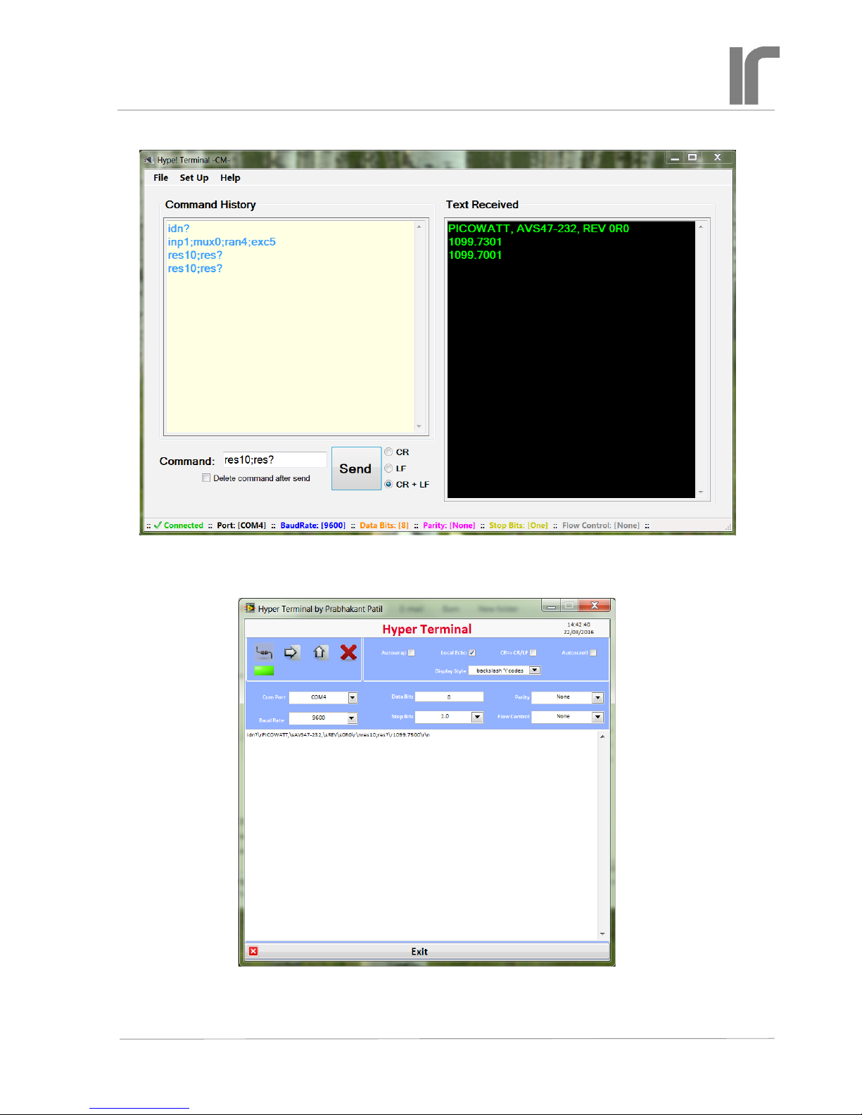
It is a good idea to get acquainted with the
AVS47-Serial/USB-W by using an RS232 hyperterminal program. It lets you control the bridge by writing commands/queries and reading the responses.
Although such a program is no longer included in
Windows, many free programs are available from
the Internet. For example, we have used
https://sourceforge.net/p/hypetermi-
nal/wiki/Home/
and, if you have LabView, you can try
https://decibel.ni.com/content/docs/
DOC-16284
See also page 9.
Commands to the AVS47-Serial/USB-W are not case
sensitive. You may insert blank space(s) between the
command and argument part. Commands “ran5”,
“RAN5”, “ran 5”, “RAN 5” or “ran 5” are all
equivalent.
The rst part of a command or query can contain
only alphabetic letters. The second, argument part of
a command, is made of integral numbers. The argument part of a query is a question mark “?” like in
“RAN ?” or “ran?”.
Several commands can be placed on a single
command line. The commands/queries must have
a command separator, or delimiter, between them
(comma or semicolon, which is the start-up default).
Your own computer program can terminate the com-
mand line either by carriage return (CR or \r, ASCII
13), by linefeed (LF or \n, ASCII 10) or by CRLF.
These are called line terminators and the box recognizes them all. The commands/queries are performed
in sequential order, the previous command must be
completed before the next one can be handled.
For example: “rem1;inp1;ran3;exc7” (quotation marks are not parts of the actual string) sets
the bridge in remote mode, sensor measuring input,
200Ω range and 10mV excitation. After having
waited for some seconds (settling time), one can take
the reading.
Maximum number of characters on one line,
including command separators and possible blanks,
is 255. Handling the commands starts after a line
terminator has been received. If the command line
is not terminated with CR, LF or CRLF, processing
will not start.
Do not issue further commands or queries before
all the commands/queries on the previous command
line have been executed.
Responses
The AVS47-Serial/USB-W obeys the principle, that
only a query can produce response. So your applica-
tion program needs not poll and read the serial port
after commands.
The only exception to this is the REPEAT command. If the repeated line contains queries, the
responses are sent automatically, and you must
decide how to read them. It is not necessary to read
responses, the buffer is emptied after each repeated
line.
Responses can consist of printable alphanumeric
characters, but most queries return only a number.
Some values are output as oating point numbers,
but exponential format is not supported. The re-
sponses do not have headers in order to make them
easier to read into a program.
If a command line consists of more than one
query, the responses are output in the corresponding
order and they are separated by the specied command separator (delimiter).
For example, command line
“ARN10;RES5;RES?;RAN?” instructs the bridge to
go to autorange mode, wait for 10 seconds after each
automatic change of range (if needed), then take a
mean of 5 A/D conversions, and place the result and
the range setting (which was possibly altered by autoranging) in the output queue. The result is sent via
the RS232 port to the computer, which must detect
that data has arrived into the serial buffer and then
read it from the buffer. The response could be like
“1234.5000;4” (i.e. 1234.5Ω; 2kΩ range).
You may save programming overhead by giving
commands for a measurement on one line. Respons-
es to queries may be easier to read into variables, if
queries are made separately for each item. Then one
does not need to remove the delimiters and parse the
response line.
The response ends by the line terminator specied by the TER command (default is CRLF). The
terminator can, but it must not, be the same for
both transmitting and receiving. The AVS47-Serial/
USB-W will always recognize any of the three line
terminators, CR, LF or CRLF.
Page 8
Revised: 2018-06-04 AVS47_serial_usb_w_userguide_1r3.indd
User
Guide 1R3
For Interfacing the AVS-47B with Computers
AVS47-Serial/USB-W CONVERTER
The “Hype! Terminal” (see text for link) is easy to use: Just specify the Com port number (SetUp) and it is ready. After identication, the bridge is set for measure input, channel 0, range 2kΩ, and excitation 300µV. Then 10 A/D conversions are taken (RES10)
and the output is read by RES?. This RS232 terminal program for a Windows PC does not require LabView.
Users of LabView can also try this program (see text for link). The output includes all printing and
non-printing characters in both transmitted and received strings, which can be useful for debugging. But
otherwise it is far less convenient to use than the previous example.
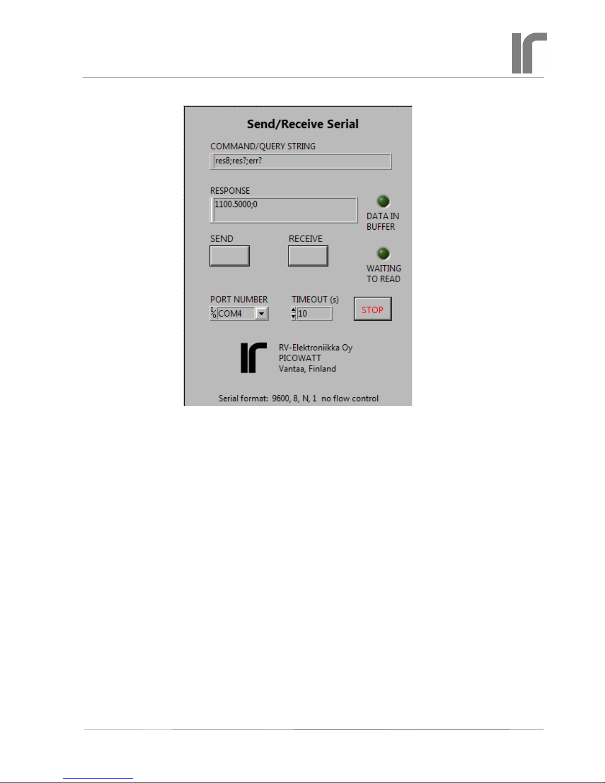
Send/Receive Serial tool
This handy LabView VI was written for developing
programs for the AVS47-Serial/USB-W. It allows
one to send commands and queries and to read the
response to queries. It requires the base version or
better of LabView2012 or later.
Check the jumper position JP203 inside the AVS47B bridge and connect the cables as was instructed
earlier. The AVS47-Serial/USB-W starts when it gets
power from the +12V mains adapter. Select the correct Com port. The serial format is xed to the most
common default, 9600,8,N,1 with no ow control.
Run the VI and click “SEND” for sending the default IDN? query. DATA IN BUFFER should light.
Click “RECEIVE” for reading the response. If this
works, make the port number default and save the VI
so that you do not need to re-enter the port number
when you load the VI next time.
Use this tool for getting acquainted with the behaviour of the software before starting to write your
own application in whatever programming language
you prefer. Labview programs recognize only ‘\n’
(newline) character for terminating the transmitted
string, but some other program may expect ‘\r’
(carriage return) or \r\n. Dene the response line
terminator by the command TER.
You can see the non-printing characters in the
response if you stop the VI, click the RESPONSE
eld and select ‘\’ Codes Display or Hex
Display from the context menu. Start the VI
again.
If you try to receive before a response is available, the program waits until the input buffer is
non-empty or timeout occurs. See the block diagram,
how this was done. You can put the OPC? query
after a time-taking command like a long average
(e.g. RES100;OPC?). The “operation complete”
query places character ‘1’ in the output queue when
averaging is ready. You do not need OPC?, if you
have only one query and put it as the last item on the
command line.
This VI can be downloaded from our WEB site at
http://www.picowatt./interfacing/computer_interfaces.html (“read and write using LabView”).
Page 9
Revised: 2018-06-04 AVS47_serial_usb_w_userguide_1r3.indd
User
Guide 1R3
For Interfacing the AVS-47B with Computers
AVS47-Serial/USB-W CONVERTER

Page 10
Revised: 2018-06-04 AVS47_serial_usb_w_userguide_1r3.indd
User
Guide 1R3
For Interfacing the AVS-47B with Computers
AVS47-Serial/USB-W CONVERTER
HARDWARE COMMANDS
INP [0..2 | ?] Input selector command/query.
0 = Grounded input (zero resistance)
1 = Measure the selected sensor channel
2 = Calibrate (bridge measures internal 100Ω)
INP? returns 0..2
MUX [0..7 | ?] Multiplexer channel command/
query. The bridge will need a settling time after
channel has been changed. The required time
is longer if excitation is low. Use the DLY
or SCK command after setup commands like
MUX, RAN and EXC, before starting to take
readings.
0..7 = sensor channel
MUX? returns 0..7
RAN [0..7 | ?] Range command/query
0 = no range is connected. No excitation can
run into the sensor, and output is random. Do
not use this value in order to avoid accidental
heating of the sensor when another range is
later selected. If you do not know the proper
range, start from 2MΩ.
FIRST COMMANDS AND QUERIES
All queries work in both remote and local modes,
so that you can read bridge settings although it is in
local. Commands that control the operation of the
AVS47-Serial/USB rmware are also effective in
both modes, whereas hardware commands to the
AVS-47B can be used only in remote. These initial
commands are for making the AVS47-Serial/USB
rmware to correspond to your application program.
The commands and responses are same for the -W
and -F versions.
IDN?, *IDN? Identication query. You can check
succesful starting and rmware version of the
AVS47-Serial/USB by this query. The response
has four comma-separated elds and is like
“PICOWATT, AVS47-Serial/USB,0, REV
1R3”. The serial number eld is identically
“0”.
HW? Hardware version query. Returns the ver-
sion of the AVS47-Serial/USB hardware. The
response is like “PICOWATT, RS232PB_A2”.
The latter item is the version of the mother
board.
AL? Alarm line query. This query transacts with
the AVS-47B bridge and checks the state of
the “AL” Picobus signal line (AL is used for
preventing multiple reads of a single A/D conversion). Response should be 1 if the bridge is
powered, if the 25/15 pin cable is in place and
everything is OK. If the response is 0, check
that the cable is plugged and OK. Re-start the
box by re-connecting its +12V power. The
bridge should end up in local mode. If AL?
still returns zero, refer to the trouble-shooting
procedure (pp. 20) or contact factory.
LIM [0..1] Select the command delimiter (or com-
mand separator).
0 = semicolon (dec ASCII 59). This is the startup default, which is used also by the IEE-488.2
standard.
1 = comma (dec ASCII 44). May be useful if a
comma-separated format (CSV) is preferred.
TER [0..3] Select the response line terminator
that the box uses for indicating the end of
its response. Depending on your computer
software, you may need to modify the default
value of CRLF. When reading the serial port,
the AVS47-Serial/USB rmware looks for both
CR and LF, and when either of them is en-
countered, the line is considered as ended. The
possibly remaining terminator is neglected.
You can modify the response line terminator by
sending the TERx command:
0 = nothing
1 = linefeed (LF, \n, dec ASCII 10)
2 = carriage return (CR, \r, dec ASCII 13)
3 = CRLF (start-up default)
REM [0..1 | ?] Remote mode command/query. The
change from local to remote does not change
the state of the bridge: the program rst reads
the setup in local mode and then sends this
setup to the bridge in remote mode. Any
hardware commands sent before the REM1
command are forgotten. The AVS-47B shows
remote mode by a yellow light on the front
panel.
0 = local
1 = remote
REM? returns 0 or 1

Page 11
Revised: 2018-06-04 AVS47_serial_usb_w_userguide_1r3.indd
User
Guide 1R3
For Interfacing the AVS-47B with Computers
AVS47-Serial/USB-W CONVERTER
1..7 = ranges from 2Ω to 2MΩ
RAN? returns 0..7
EXC [0..7 | ?] Excitation command/query. Excita-
tion voltage, as the term is used in the context
of the AVS-47B, means the RMS voltage
across a sensor whose value is half of the selected range. Excitation is symmetrical square
wave -shaped current at about 13.7Hz.
0 = no excitation
1..7 = 3µV, 10µV, 30µV...3mV
EXC? returns 0..7.
REF [0..20000] Reference command for
deviation (ΔR) measurements. For example,
REF10000 sets the AVS-47B’s reference DAC
to 1 Volt, which corresponds to the middle of
any currently selected resistance range.
The resulting DAC voltage can be measured
by switching the ADC input to DIS3 (the
internal reference). Then issue ADCx for
measuring the output voltage of the DAC.
The programmed reference DAC has only 12
bits (0..4095), whereas the 0..20000 output of
the bridge corresponds to about 14 bits.The
reference value is therefore divided internally
by 5 for scaling it to range 0..4000. The DAC
output changes in steps of 5 digits (500μV)
and has a typical accuracy of a low-cost 12-bit
D/A converter.
NULDEV [1..100] Null deviation command.
This is a macro command that measures
whatever was previously selected by the DIS
command and then sends this value to the
reference DAC. The argument determines,
how many A/D conversions are used for the
measurement. A longer average improves accuracy if readings are noisy.
This command is intended to be used only
with DIS0. The REF POT / REF MEM front
panel switch must be in REF MEM position.
After the NULDEV command, the rear panel
DIFFERENCE BNC output is near to zero.
Select DIS1 for measuring the difference.
RFS? Reference source query.
The deviation signal VdR, is the difference
between measured resistance value (analog
voltage from the self-balancing circuitry) and
the reference voltage. The reference voltage,
in turn, can be either the output voltage from
the reference DAC or the voltage of the front
panel potentiometer. This selection is made by
the front panel REF POT/REF MEM -switch.
There is no remote command for changing the
switch position.
The reference DAC is programmed remotely
by sending the REFx command (see above). It
can also be programmed manually by lifting
the SET REF switch momentarily. Then the
DAC takes the displayed reading as input. Deviation can be nulled this way manually. The
NULDEV command is for making it remotely.
In remote-controlled applications, the refer-
ence-source switch should be in REF MEM
position. You can verify this by quering RFS?.
The response is:
0 = reference DAC (reference memory)
1 = front panel potentiometer
MAG? Magnier query
The deviation voltage VdR can be amplied by
a factor of 10. Amplication is made by a simple circuit and is therefore not very accurate.
The ΔRx10 mode is suitable for recording
only small changes, not for measuring absolute values. It is best when excitation is high
and readings therefore less noisy. Magnication can be selected only manually. MAG?
returns
0 = 1xΔR
1 = 10xΔR
MEASUREMENT AND READOUT
COMMANDS/QUERIES
These commands are for determining the A/D converter input, for making single or averaged A/D conversions, and for reading the result. There is also a
command for detecting the possible ADC overrange.
DIS [0..7 | ?] Display selector command
This command selects one of 8 possible voltages to be measured. The current selection can
be queried by DIS?.
Use the RES command and query only when

Page 12
Revised: 2018-06-04 AVS47_serial_usb_w_userguide_1r3.indd
User
Guide 1R3
For Interfacing the AVS-47B with Computers
AVS47-Serial/USB-W CONVERTER
displaying DIS0 and DIS1. The RES? query
can also be used for reading item 7 (Set point
of the old TS-530A temperature controller).
Then you get the set point in resistance, scaled
correctly by the currently selected measuring range. However, because of the very old
design, the TS-530A set point cannot be given
in resistance but it must be given as an integer.
Refer to the “SPT” command below.
Use the ADC command and query for all
other display items than 0,1 and 7 because
the RES values are scaled by the currently
selected measuring range. The ADC? query
returns integers -19999..19999 corresponding
to its input voltages from -2V to +2V. Refer
to the AVS-47B manual for how to use the
various display items.
0= Voltage proportional to the sensor value R
1= Deviation ΔR between R and the reference
2= Adjust reference. This is the voltage from
the front panel potentiometer
3= Reference. This is output voltage from the
reference D/A converter
4= Excitation voltage. This is the approximate
excitation voltage across the sensor. Useful
only on the lowest resistance ranges and
high excitation. Can be used for estimating
current lead resistance.
5= 530A heater voltage, (amplied inside TS-
530A, negative reading)
6= TS-530A heater current (actually, voltage
across current sense resistor in volts)
7= TS-530A set point voltage (V).
ADC [1..1000 ] A/D conversion command
The A/D conversion is made from voltage that
has been previously selected for measurement
by using the DISn command. The ADC command can be used both in local and remote
modes.
ADC1 makes one single measurement, ADCn
makes n successive measurements and calculates their average. Conversions take 0.4
seconds each, rate is 2.5 conversions/second.
If the result is an exact zero, the conversion is
automatically repeated for detecting possible
overrange (because the ICL7135 ADC yields
a blinking zero in case of an overload.
ADC? A/D conversion query
This query returns the mean value of n conversions (see above). The conversion result
is given as an integer -19999 to 19999 for
ADC input voltages -2V..+2V. Polarity is
indicated by minus sign and it is also returned
by the POL? query. Use ADCn and ADC? at
least for measuring items 4..6, which are not
directly dependent on range. Use RESn and
RES? for measuring intems 0, 1 or 7. Items 2
and 3 can be measured using either command.
If the ADC’s range is exceeded the result is an
exact zero, which can be distinguished from a
real zero by checking OVR? See also OVR?
and ARN.
ADC? query can be preceded either by an
ADCn or RESn command. They are one and
the same function. The result is valid until the
next ADC/RES command.
RES [1..1000] A/D conversion command for
resistance.
The ADC reading is scaled by the currently
selected resistance range, therefore measure-
ment of display items 4-6 can produce misleading results.
RES1 makes a single conversion, RESn
makes n successive measurements at 0.4
second intervals and their mean value is calculated.
If the A/D converter outputs an exact zero, the
conversion is automatically repeated for detecting a possible overload. The OVR? check
should be a routine part of your application
program.
RES? Query for resistance
Resistance is output as a oating point number
with four decimal places for R and ΔR displays, and with ve decimal places for 10xΔR
display. It is scaled by the currently selected
resistance range. The reading may include
a preceding minus sign. Arduino Mega2560
does not support output in exponential form.
RES? query can be preceded either by an
ADCn or RESn command, they are actually
one and the same function. The result is valid
until the next ADC/RES command.

Page 13
Revised: 2018-06-04 AVS47_serial_usb_w_userguide_1r3.indd
User
Guide 1R3
For Interfacing the AVS-47B with Computers
AVS47-Serial/USB-W CONVERTER
POL? Polarity query
The ADC? and RES? return values are preceded by a minus-sign if the reading is negative.
You will probably not need this query, it is
used by the rmware. POL? returns
0= negative
1= positive
OVR?, OVL? Overrange query.
An overrange-reading from the ICL7135 ADC
is an exact zero, which can be distinquished
from a true zero by repeating once each measurement that yields an exact zero. A BUSY bit
from the A/D converter alternates if overrange, which separates these two cases. The
AVS47-Serial/USB does this check automati-
cally.
If a single A/D conversion is made by using
ADC or RES command and the result is overrange, the ADC? reading is coerced to 20001
and the RES? reading is coerced to 2000100.0
which both are impossible readings in normal
operation. In addition, the OVR? bit is 1 and
ERR? is “ADC overload”.
If n in ADCn or RESn is greater than
1, the average may contain one or more overrange- readings. No coercion is made, as the
average can still be useful. Overrange detections are internally OR’ed together. OVR?=1
then indicates that the nal average contains at
least one overrange reading (which is 0). Such
an average is distorted and perhaps it should
not be used.
If there is any possibility for such a situation, use autoranging. It will react to the rst
overranged conversion and, after autoranging
and autoranging delay, averaging is re-started.
This quarantees a correct mean value.
OVR? returns:
0= no overrange
1= reading was overrange, or at least one sample in the average was overrange.
OVR? gets information from the A/D conversions. Do not use OVR? alone without a preceding ADCx conversion command. Instead,
reading the conversion result is not necessary
for asking OVR?.
MIN?, MAX? These queries return the minimum
and maximum resistance values (in ohms) of
conversions averaged for one RESn or ADCn
command.
STD? Standard deviation of the averaged A/D
conversions as resistance in ohms. Use a long
average for getting a reliable STD. If noise is
purely random and white, STD is proportional
to the noise at the bridge input. If data has a
trend, STD is not useful.
QRATIO? This is simply (MAX-MIN)/STD. For
a purely random white noise, QRATIO is
about 5. A much higher gure may tell about
external interference in data, whereas a much
lower gure can tell about insufcient number
of samples. QRATIO is also affected by the
digitising step if excitation is high. It is most
useful at low excitations.
REPEAT This command repeats one command
line continuously. The commands and queries
behave excactly similarly as if only one line
were sent. If the line includes queries, the
CPU sends responses automatically and your
program can read them as they come. This is
an exception to the rule that the CPU does
not send anything by itself, without an explicit
query. Repeating is stopped by sending any-
thing via the RS232 line. An example using a
hyperterminal program:
ADC5;ADC?;REPEAT
response:
12345
12346
12344 etc.
The REPEAT command must be the last item
on a command line. In the repeating state,
the bridge gives new readings 2.5 times/second. Your application program can read all
responses as they come, or you can read only
when readings are needed. There is no buffer
for saving old results in the CPU.
Stop continuous repeating by sending rst
any character to the CPU and give then new
instructions on a new command line.

Page 14
Revised: 2018-06-04 AVS47_serial_usb_w_userguide_1r3.indd
User
Guide 1R3
For Interfacing the AVS-47B with Computers
AVS47-Serial/USB-W CONVERTER
ARN [0..30] Autorange mode command.
In autorange mode, the absolute value of each
A/D conversion result is compared against
two limits:
• If lower than 1800 (out of 19999), range is
changed downwards, provided that it is not
already 2Ω.
• If the reading is higher than 19900, the range
is changed upwards, provided that it is not
already 2MΩ.
• If the argument in ADCn or RESn is greater
than 1 (average of many conversions), the
rst encountered overloaded or underranged
conversion causes an autoranging operation,
and after a delay, averaging is started from the
beginning. This guarantees a correct average.
The ICL7135 ADC circuit is overloaded, if
reading exceeds 19999. Then the AVS-47B
front panel display shows blinking zeros and
an internal overload indicator blinks between
true and false. During overload, a measurement like ADC;ADC? returns an exact zero,
which cannot be distinguished from a real
exact zero.
Because of this uncertainty, the AVS47Serial/USB repeats once any conversion that
returned zero, which enables detection of
overload. The overload indicator is set to 1
(queried by OVR?).
ARN 0 means manual ranging. Argument
higher than 0 enables autoranging. A value
between 1 and 30 determines, in seconds, how
long the system waits after having changed
the range until a new autorange operation can
take place or until any new command can be
performed. A time like 5 seconds may sufce
at high excitations, when the bridge settles
quickly. A longer time, up to 15-20 seconds,
should be used at the lowest excitation in order to guarantee good balance before readings
are taken.
If the resistance changes several
decades, which is typical when switching
channel, the settling delay time of x seconds
is applied after each change of range. This
can make scanning unnecessarily slow or too
fast for good settling, but you can avoid it
OTHER COMMANDS AND QUERIES
OPC? Operation complete query
This query can be placed after slow operations, like long averaging. When encountered,
it places a “1” into the output queue. It should
be the last item on a command row.
DLY [0..30] Delay command
The argument is delay time in seconds. Use
DLY for giving the AVS-47B time to settle
after a change in channel, range or excitation.
Note that autorange has its own settling delay
after each change of range before starting to
make A/D conversions. This delay is determined by n in ARNn (see ARN).
SCK[1..10] This “sign-check” function is an alter-
native to the xed DLY delay. It is useful after
a change in range or input channel. When
the command interpreter encounters SCKn,
the function starts to make A/D conversions
at maximum speed and form differences
between successive readings. This continues
until two successive differences have had op-
posite signs n times, or the function has found
n sets of 3 successive equal readings. Then the
function concludes that data is either within
the peak-to-peak noise or it has settled to
within display resolution. The function exits
and operation continues with the next command, which is typically ADCn.
by using the SCK[1..10] command. Refer to
description of SCK.
Use the RAN? query if you want to check the
range that was possibly changed by ARN.
Autoranging is especially useful in scanning.
If you do not use autoranging, you MUST
check with OVR? whether the single conversion or the average contained overload.
NOTE: The AVS-47B’s hardware autorang-
ing must not be enabled when the bridge is
under remote control. This would cause a rival
condition.

Page 15
Revised: 2018-06-04 AVS47_serial_usb_w_userguide_1r3.indd
User
Guide 1R3
For Interfacing the AVS-47B with Computers
AVS47-Serial/USB-W CONVERTER
makes one conversion, if there is no overload. The result is not used. SCK5 expects
differences to change sign n=5 times, which
indicates a reasonably good settling. Finally
an average is taken and the result is asked.
If the sensor’s value exceeds the range or is
below underrange limit (1800 counts), autoranging must act. ADC1 will then make so
many autoranging operations that are needed
for nding a correct range. Because settling
on a low excitation is very slow, a long autoranging delay (like the suggested 30 seconds) is necessary. A too short delay can cause
oscillation between ranges and this condition
should be strictly avoided - one has to reboot
the CPU by disconnecting its power! Once a
correct range has been found, SCK5 checks
for nal settling.
The long autoranging delay slows down
scanning when autoranging is needed. As soon
as the preset ranges are correct again, which
is the normal situation, scanning is faster
because xed settling delays are replaced
by SCK. It takes only the required time, not
more.
RST Reset command
This command works only when the program
is idling, i.e.it is not extracting commands
from a previously received command line or
performing those commands. RST cannot be
used for stopping long averaging or any other
pending operation. In such a case, wait or
reboot the interface.
The RST command sets the AVS-47B into
a known safe state: input 200Ω, channel 0,
range 2M, excitation 3µV and display to
R (resistance). Response line terminator is
CRLF and command separator is semicolon.
The AVS-47B is left in local mode, which is
shown by the blanked REMOTE light.
RST works differently than initial power-on
start: both leave the bridge in local mode, but
start-up does no alter the previous local-mode
settings of the bridge whereas RST changes
settings to these “safe values”.
The SCK function cannot prevent the A/D
converter from being overloaded. In such
a case, the ADC outputs only zeros. SCK
behaves as if it had received three equal readings (zeros in this case) and exits without any
additional delay.
The described method does not work if the
data has a trend that is large enough to prevent
differences from changing their sign. If there
is such a trend, the function exits after a timeout of about 30 seconds.
The function is faster if n is small, but then the
data may not have settled properly. A large n
guarantees better settling but is slower.
Some examples on how SCK could be used:
RAN3;SCK4;RES10;RES?
MUX4;RAN5;EXC2;SCK5;RES10;RES?
SCK works nicely if the measured resistance
is within the selected range. In case of ADC
overload, SCK exits quickly and the succeeding A/D conversion yields a zero resistance.
This can be prevented by using autorange,
but autoranging does not solve the problem of
good settling. Scanning is a situation where
a good tradeoff between speed and settling
accuracy is difcult to nd. Following is just
an idea of how automatic scanning could be
programmed.
Autoranging is enabled by ARN30 or some
other long delay. After having measured a
scanned sensor, its range is asked by RAN?
and saved as a variable for this channel. The
command line could be
EXC1;MUXnew;RANnew;EXCnew;SCK1;
ADC1;SCK5;RESn;RES?
Explanation: EXC1 selects the lowest excitation for preventing unintentional heating of
the next sensor during switching. MUXnew
selects the new channel. RANnew is the
stored range that was previously good for this
sensor. EXCnew is the suitable excitation for
this sensor. All these come into effect immediately.
The bridge starts to slew toward the new
sensor’s value. SCK1 waits until the slewing
changes direction for the rst time. ADC1

Page 16
Revised: 2018-06-04 AVS47_serial_usb_w_userguide_1r3.indd
User
Guide 1R3
For Interfacing the AVS-47B with Computers
AVS47-Serial/USB-W CONVERTER
COMMANDS FOR THE TS-530A TEMPERATURE CONTROLLER
The TS-530A is a very old design, and it has
been discontinued. We offer now a low-cost
analog temperature controller option for the
AVS-48 bridge. However, the AVS47-Serial/
USB includes also commands for the TS-
530A. They are for customers, who already
own this controller. These commands have no
corresponding queries. The analog setpoint
voltage, the heater output voltage and the
heater current can be measured by the A/D
converter of the AVS-47B bridge (see the DIS
command and refer also to the TS-530A and
AVS-47B manuals).
The TS-530A must be connected to the
AVS-47B with the supplied 37-way ribbon
cable for data and with the supplied short
BNC-BNC coaxial cable for the analog output
from the bridge.
The TS-530A does not have a separate
“remote” mode. Neither can the front panel
settings be read remotely. This means that
one can -but should not- change the remotely
programmed PID settings by using the TS530A front panel switches, and the rmware
has no way to detect it. If this appears to be a
problem, write your program so that the settings of the TS-530A are updated frequently.
Re-programming existing settings without
changing them will not disturb the analog control circuitry in any way.
SPT [10..42000] Set point command
Set point is given as a long integer from 10 to
42000. One digit corresponds to 100µV and
the range is from 1mV to 4.2 Volts although
only voltages up to 2V are meaningful when
using 530 with the AVS-47B. The slow integrating D/A converter of the TS-530A is very
accurate and linear, but it does not go to exact
zero, therefore 1mV is the minimum. Arguments less than 10 are coerced to 10.
If you want to give the set point in resistance, you must scale and convert it yourself
to a long or unsigned integer suitable for this
converter. For example, SPT10000 produces
ERR? Error query
The AVS47-Serial/USB has limited error
reporting capability. Errors are not reported
automatically, they must be queried using the
ERR? query. Possible responses:
0: No error
command XXXyyy not recognized:
The letter part of a command has been misspelled or is non-existent
query XXX? not recognized: The
letter part of a query has been misspelled or is
non-existent.
argument in XXXyyy exceeds
maximum:
argument in XXXyyy less than
minimum:
Every command has upper and lower limits
for its argument. If the given argument is
outside these limits, it is coerced to the nearest
limit and an error message is available.
AL input line (No 4 black in -F
version) stays at 0:
This input line from the bridge to the CPU is
used for synchronising the operation so that
each A/D conversion is read only once. The
error message is for trouble-shooting in a case
where communication fails.
ADC overload: The input voltage to the
ADC has exceeded 1.9999 Volts, which is
equivalent to the upper limit of each resistance
measuring range.
timeout in SCK: The sign-checking
delay function has not found expected criteria.
Reasons can be abnormally slow settling or
a trend in data. The function will exit after
a timeout. Then this error message becomes
available.
Error messages from one command line are
chained. The messages are verbal instead
of being numerical codes because they are
intended to be only programming aids. The
application program should minimise the pos-
sibility of error situations.
Error register is cleared by ERR?

Page 17
Revised: 2018-06-04 AVS47_serial_usb_w_userguide_1r3.indd
User
Guide 1R3
For Interfacing the AVS-47B with Computers
AVS47-Serial/USB-W CONVERTER
POW [0..7] Heater power range command
Power ranges are calculated for a 100Ω heater.
If heater resistance is higher, output voltage
compliance (about 10V) will reduce the maximum power. If heater resistance is lower, the
available output current (100mA) will reduce
the maximum possible output.
0: Heater output is disabled
1..7: 1μW-10μW-100μW...1W
The heater output stage has seven current
sensing resistors 10kΩ, 3.16kΩ, 1kΩ, 316Ω,
100Ω, 31.6Ω and 10Ω corresponding to heater
ranges 1μW..1W. One volt across a sensing
resistor means full output of the range. Based
on the above gures, you can calculate correct
ranges for heaters other than 100Ω. Similarly,
you can measure the output current using
DIS6 and calculate the heating power from
RH*I2.
a 1 Volt setpoint. If the AVS-47B measures
on range RAN (=1..7), calculate the set point
integer from set point resistance RS as follows:
SPT = RS / (10 ^ (RAN-1)) * 10000
where RS=setpoint in ohms
If desired set point is e.g. 110
ohms and range=200R, (RAN=3)
SPT = 110/(10^(3-1)) * 10000 =
11000
PRO [0..11] Proportional gain command
Gain increases in steps of ve decibels. Values
are very approximate.
0..14: 5-10-15-20...60dB
15: no gain. Input of the proportional ampli-
er is connected to ground.
ITC [0..15] Integrator time constant command.
Values are very approximate.
0: integrator is reset to zero. P and PD mode
control
1-10: 1-2-5-10-20..1000s. Higher number
means weaker integration
11: analog integrator is latched by leaving its
input open
12..15: integrator is reset to zero. Same as
ITC=0.
DTC [0..7] Derivator time constant command.
Values are very approximate.
0: No derivation. P and PI mode control.
1..7: 1-2-5-10-20-50-100s
Higher number means stronger derivation.
High proportional gain with strong derivation leads easily to oscillation of the control
system.
BIA [0..5] Power bias command
Power bias can be used to reduce control error
in P and PD modes. It is not useful in PI or
PID modes.
0..5: 0-20-40-60-80-100% of maximum
heater power. The highest setting is sufcient for maximum output on the selected
heater range when proportional input is
zero and integrator is reset.

Page 18
Revised: 2018-06-04 AVS47_serial_usb_w_userguide_1r3.indd
User
Guide 1R3
For Interfacing the AVS-47B with Computers
AVS47-Serial/USB-W CONVERTER
CABLE SPECIFICATIONS
The AVS47-Serial/USB comes with two cables,
Picobus Cable and Serial Cable. The 5 meter Picobus cable connects the converter to the AVS-47B
and the 1.5 meter Serial cable connects the box to
the computer directly or via an USB-232 converter.
This Picobus cable is distinguished from the Picobus
cable that is supplied with the AVS-47B by its male
25- and 15 pin D-connectors. The resistance bridge
is supplied with a cable that has male and female 25way D-connectors.
Picobus Cable (PB25P15P6W5M)
The male DB25P and male DA15P are connected
by a braided (shielded) cable with 6 conductors (e.g.
Tasker C6015). Length: 5 meters.
DB25P DA15P Description
1 - braid grounded only in DB25P
4 4 CP clock from box to bridge
5 5 DI data from bridge to box
6 6 AL alarm line from bridge to box
7 7 Isolated ground
20 15 DC data from box to bridge
9 9 Isolated +5V (referred to pin 7)
Other pins are unused.
Note that the shielding braid must remain isolated
from everything inside the 15-pin connector shell. A
100nF ceramic capacitor with shortest possible leads
connects the braid to the connector shell. The braid
is connected to the shell of the 25-way connector at
the AVS-47B end.
This arrangement prevents the cable from act-
ing as an antenna at high frequencies while not
providing a path for ground currents at the mains
frequency. Inside the AVS-47B, Picobus signals and
its power supply are galvanically isolated from the
bridge ground .
Serial Cable (RS9P9S7W1.5M)
The male DE9P and female DE9S are connected
by a braided 1:1 cable of 6 conductors (e.g. Tasker
C6015). Length: 1.5 meters.
DE9S
DE9P RS232 Description
1 - -
6 DSR AL for Picobus applications
2 RXD RS232 output box=>computer
7 RTS CP for Picobus applications
3 TXD RS232 input computer=>box
8 CTS DI for Picobus applications
4 DTR DC for Picobus applications
9 5 Computer ground = shielding braid
Shielding braid is connected, in addition to pins 5,
also to both connector shells.

Page 19
Revised: 2018-06-04 AVS47_serial_usb_w_userguide_1r3.indd
User
Guide 1R3
For Interfacing the AVS-47B with Computers
AVS47-Serial/USB-W CONVERTER
RE-PROGRAMMING THE AVS47-Serial/
USB-W
The rmware can be updated by reprogramming the
Arduino Mega2560 board. In order to do this, you
need
- a USB cable (type A/B)
- Arduino development software for Mega2560. This
can be downloaded from Arduino WEB site.
- The new rmware version. It is available from us.
1. Follow Arduino’s instructions to download
and install their programming environment
software.
2. Open the four screws holding the “front” pan-
el of the AVS47-Serial/USB, the panel with
the DA15 connector. There must be no cable
from this connector to the AVS-47B. Plug the
“A” type connector into the USB connector of
your computer and the “B” end into the “hidden” USB connector inside the AVS47-Serial/
USB. The box will now start, because it gets
power from the USB.
3. Make on your hard disk a directory that has
the same name as the new rmware le,
but without extension, e.g. “avs47_serial_
usb_1r2” . Arduino saves source codes into
directories that have the same basename as the
source code le. It creates such directories automatically, so it is best to create the directory
yourself in a place where you want it be.
4. Place the new version of the rmware (e.g.
“avs47_serial_usb_1r2.ino” in the new
directory (Arduino calls the source code a
“sketch”).
5. Start the Arduino environment. Under Tools,
select Arduino Mega2560 board type. Select
also the USB port that your computer has assigned to the CPU box.
6. Under the File menu, navigate to the new
rmware version and open it into the environment.
7. Under the Sketch menu, select UPLOAD. If
you do not get any error messages, updating
has been done in a few seconds. You can now
detach the USB cable, x the rear panel and
connect the 25/15 Picobus cable to the resistance bridge and the -12V power plug. Then
test the new rmware using an RS232 terminal program or your own software. Suggestion: start conversation always by issuing the
IDN? query.
Before we email an updated version to you, please
check and tell us your old rmware version so, that
we can send also the old version for backup.
AVS47-Serial/USB-W TROUBLE
SHOOTING IDEAS
If you have difculties in getting the AVS47-Serial/
USB-W protocol converter to work, you can try the
following trouble-shooting procedure. The problem
might not be found this way, but it at least gives us
valuable knowledge of where in the system the problem probably is. For making these tests, you need a
hyperterminal program, or any other program that
allows you to send serial commands to the AVS47Serial/USB-W and read the responses. Typically,
today’s computers have only USB ports and then
you need a USB-232 adapter between the computer
and the protocol converter box.
Communication between the bridge and the box
uses four signals, two from the box to the bridge and
two from the bridge to the box. They are

Page 20
Revised: 2018-06-04 AVS47_serial_usb_w_userguide_1r3.indd
User
Guide 1R3
For Interfacing the AVS-47B with Computers
AVS47-Serial/USB-W CONVERTER
AL: “alarm” line telling that an A/D conversion is
ready to be read from the bridge
DI: data bits from the bridge (“instrument”) to the
box
CP: clock pulses from the box to the bridge
DC: data bits from the box (seen as the “computer”
by the AVS) to the bridge.
The sent and received data bits are synchronized
to the clock. Communication between the box and
the bridge is based on our proprietary synchronous,
serial “Picobus” protocol. Although this communication is serial, it is NOT RS232. Please do not mix
synchronous and asynchronous serial formats. In
synchronous Picobus communication, a 48 bits long
string contains the complete state of the bridge,
which is sent in every transaction. While sending
the string, the CPU reads a response from the bridge
using the same clock pulses for synchronisation. The
response contains the state of the bridge just before
the transaction. Asynchronous serial communication
between the CPU box and the computer, on the other
hand, uses short mnemonic commands for control-
ling individual bridge settings and queries for read-
ing conversion results and settings that are currently
in effect.
The expression “protocol converter” means that
the complicated synchronous protocol of the bridge
is programmatically turned to understandable commands and arguments which are sent and received in
serial format that uses the legacy RS232 hardware
standard. Because of the slow speed of the AVS-47B
and tiny amounts of data, the simplest possible protocol can be used (9600 bauds, 8 data bits, no parity
and one stop bit. No handshaking). It is based on
signals called TxD, RxD and ground. TxD transfers
data from the external computer to the box, and RxD
from the box back to the computer.
Signal lines between the CPU box and the computer are not galvanically isolated, whereas communication between the CPU and the bridge is optically
isolated.
PROCEDURE
1) Remove the four cross-head screws that hold the
rear panel of the box (the panel with the 15-way
connector). Then pull of the top cover lid. If it
will not come, loosen also two topmost screws on
the opposite side. Place the box, so that the rear
panel is to the left. You can see a row of several
green and two red LEDs. They are for trouble
shooting. LEDs on the left (“bridge side”) show
signals to an from the primary interface of the
AVS-47B. They are marked with AL, DI, CP and
DC. At right are the two asynchronous signals,
TxD and RxD. The DI, AL, CP and DC signals
on the right have no meaning in this AVS47-Serial/USB-W application.
2) Connect the serial cable (RS9P9S7W1.5M) from
the box to the USB-232 converter or to your
computer, if it has a physical COM: port (RS232
port). Do not yet connect the cable to the resistance bridge.
3) Connect the +12V DC power plug. The green
“ON” light and one yellow LED on the Arduino
board should turn on. All trouble-shooting LEDs
(except possibly TxD, CP or DC on the right)
should be off.
4) Send command RST (“reset”) from the computer.
You should see very short activity of the TxD
LED. It is not dependent on the Arduino board.
If you do not see any activity although power is
ON, your computer program may be congured
wrong, or the cable is not in condition. If you are
not using our original cable, please check that
it is wired 1:1. Pins 2 of both connectors must
have been connected together, and also pins 3.
Pins number 5 are ground. (The so-called “null
modem cable” has cross-connected pins 2 and 3.
It is not suitable, because the cross-connection is
made inside the CPU box).
5) Send command IDN?. This should return
“PICOWATT,AVS47-SERIAL/USB,0,1R3” (or
a later revision). You should now see activity
also at the RxD light. The rmware program has
started succesfully. Much of the Arduino board
seems to be in order.
6) Send command RTS1. The green CP light on the
left “bridge side” turns on.
7) Send command DTR1. The DC light should turn
on. If this and 6) work, the CPU can send data
to the bridge.
8) Send commands CTS? and DSR? in turn. Both
queries should return 0 to the computer. These
signals have not yet been asserted by the bridge.

LabView is a trade mark of National Instruments, USA.
Page 21
Revised: 2018-06-04 AVS47_serial_usb_w_userguide_1r3.indd
User
Guide 1R3
For Interfacing the AVS-47B with Computers
AVS47-Serial/USB-W CONVERTER
9) Using a short piece of wire, connect pin 4 to
adjacent pin 5 in upper row of the 15-way connector. The pins are counted 1..8 from top right
to left and then 9..15 from low right to left. The
“DI“ LED should turn on and query CTS? from
the computer should return 1. Data can be received from CPU to computer.
10) Move the wire between pins 4 and 6. The “AL”
LED should turn on and query DSR? should
return 1. The Alarm signal can be received.
11) Remove the piece of wire. Send the RST command again and the lighted LEDs should go off.
12) With the AVS-47B off, connect it to the box
using the 25-to-15 pin cable (PB25P15P6W5M).
Turn on the bridge. The “AL” LED should light.
If this did not happen, the problem may be in
the cable or optoisolator ISO204 (AL) in the
bridge. Set the bridge manually for CAL, 200Ω
range, 3mV excitation and R display.
13) Send command REM1. This should set the
bridge in remote mode, shown by the yellow
REMOTE led on the front panel. The bridge state
should have remained unchanged.
If the bridge remained in local mode, the
problem may be in the cable or in optoisolators
ISO201 or ISO202 in the bridge. The cable specication is elsewhere in this manual.
14) Send command RAN4. The range should advance from 200Ω to 2kΩ. There should be no
problems with this command, if the previous ones
have worked. This veries that bridge settings
can be remotely controlled. You may also want to
test commands MUX, EXC and DIS.
15) Send command ADC10. Ten A/D conversions
are made at 0.4 second intervals. All four LEDs
on the bridge section should show activity. The
rmware resets the AL signal and then waits max
0.4 seconds until the next conversion turns AL
on. A reading is taken and AL is reset again. The
cycle repeats 10 times. Query ADC? returns the
average of the 10 conversions.
If the response is zero or something strange, or
if the DI led does not blink, optoisolator ISO203
in the bridge may be defective.
RV-Elektroniikka Oy Picowatt
Veromiehentie 14
FI-01510 VANTAA
Finland
e-mail: reijo.voutilainen@picowatt.
WEB: www.picowatt.
If all these tests ended up succesfully, your problem
may be in the application program.
If the test stops to a failure, please let us know
your results so that we can try to help.

DECLARATION OF CONFORMITY
Manufacturer: RV-Elektroniikka Oy Picowatt
Address: Veromiehentie 14
01510 VANTAA
Finland
Telephone: +358 50 337 5192
E-Mail: reijo.voutilainen@picowatt.
declares that under our sole responsibility
Product Name: AVS47-Serial/USB-W Converter
Product Description: Protocol Converter between the Picobus Primary interface of the
AVS-47B Resistance Bridge and RS232 or USB port of an external
computer.
is in conformity with the following Directives:
2004/108/EC: Electromagnetic Compatibility
2011/65/EU: ROHS Directive
and that the following harmonized standards have been applied:
EN 50 081-1: Generic emission standard, Part 1: Residential, commercial and
light industry
EN 50 082-1: Generic immunity standard, Part 1: Residential, commercial and
light industry
EN 50 581: ROHS
Additional information: This product uses +12V power from an external
mains adapter.
Vantaa, 14 March 2016 RV-Elektroniikka Oy Picowatt
Reijo Voutilainen
President

Page 23
Revised: 2018-06-04 AVS47_serial_usb_w_userguide_1r3.indd
User
Guide 1R3
For Interfacing the AVS-47B with Computers
AVS47-Serial/USB-W CONVERTER
INDEX
A
ADC 12
A/D conversion command 12
AL 18
AL? 10
Alarm line query 10
AL Picobus signal line 10
Arduino 5
Arduino Mega2560 5, 19
Argument part 7
Asynchronous 5
Autorange mode 13
Autoranging 14
Autoranging, hardware 14
AVS47-232 4
AVS47-IB 4
AVS-48 Resistance Bridge 16
B
Background 4
BIA 17
Bias power command 17
Blinking zero 12
Blinking zeros 14
C
Cable specications 18
Carriage return character 9
Case sensitivity of commands 7
Command delimiter 7
Command delimiter cmd. 10
Command line 7
Command part 7
Command separator 7
Comma-separated format 10
CP 18
CTS 18
Current sensing resistors 17
D
DC 18
D-connectors 18
Delay command 14
Delimiter 7
Derivator time constant cmd. 17
Deviation 11
DI 18
DIFFERENCE output 11
Directory 19
DIS 11
Disable heater output 17
Display selector cmd. 11
DLY 10, 14
DSR 18
DTC 17
DTR 18
E
Environment, Arduino 19
ERR error query 16
Excitation command 11
Excitation voltage 12
Exponential format 7
G
GPIB-Picobus 4
H
Hardware version query 10
Heater current of TS-530A 12
Heater power range cmd. 17
Heater resistance 17
Heater voltage of TS-530A 12
HW? 10
Hyperterminal 7
I
Identication query 10
Idle 15
IDN? 10
IEE-488.2 10
INP 10
Input selector command 10
Integrator time constant cmd. 17
Isolation, galvanic 4
ITC 17
J
Jumper JP203, AVS-47B 9
L
LabView 4, 9
LIM 10
Line terminator 6, 7
Line terminator command 10
Linux computer 4
Local 15
M
Mac computer 4
MAG 11
Magnier query 11

Page 24
Revised: 2018-06-04 AVS47_serial_usb_w_userguide_1r3.indd
User
Guide 1R3
For Interfacing the AVS-47B with Computers
AVS47-Serial/USB-W CONVERTER
Maximum number of characters 7
MAX? maximum query 13
MIN? minimum query 13
Multiplexer channel cmd. 10
MUX 10
N
Newline character 9
NULDEV 11
O
OPC 14
Operation complete query 14
Oscillation between ranges 15
Overload 14
Overrange 12
Overrange query 13
OVL 13
OVR 12, 13, 14
P
Picobus 4
Picobus cable 18
Picobus communication 4
POL 12
Polarity query 12
POW 17
Power bias command 17
Power-on start 15
PRO 17
Proportional gain command 17
Protocol converter 4
Q
QRATIO? “quality ratio” query 13
Query 7
R
RAN 10
Range command 10
Rebooting 15
REF 11
Reference command 11
REF POT / REF MEM 11
REM 10
Remote mode 15
Remote mode command 10
REPEAT command 13
RES 11, 12
Resetting the box 6
Resistance measurement cmd. 12
Response headers 7
Responses 7
Revision history 25
RFS 11
RS232 format 5, 6
RST reset command 6, 15
RTS 18
RXD 18
S
Safe state 15
Scanning 4, 15
SCK sign-checking delay 14
Send/Receive Serial 9
Serial cable 18
Serial format 9
Set point command 16
Set point of TS-530A 11
set point voltage of TS-530A 12
SET REF switch 11
Settling time 10, 14
Short circuit pieces 5
Sketch 19
SPT 12, 16
STD? standard deviation query 13
Synchronous 5
T
TER 7, 9, 10
Trouble shooting 19
TS-530A 11, 16
TXD 18
U
Underrange 14
USB-232 converter 5, 6
USB-232 Converter 4, 18
USB cable 19
USB connector 19
USB-Picobus 4
V
Voltage levels 5
W
Warranty 3

Page 25
Revised: 2018-06-04 AVS47_serial_usb_w_userguide_1r3.indd
User
Guide 1R3
For Interfacing the AVS-47B with Computers
AVS47-Serial/USB-W CONVERTER
REVISION HISTORY
1R0 => 1R1 2016-07-15
New DTR and RTS commands
New DSR? and CTS? queries
Timeout if AL is not set within 1 sec
1R1 => 1R2 2018-03-25
Correction in ADC function
New queries MIN?, MAX?, STD?, QRATIO?
Correction in operation of OVR query
Correction in operation of ERR? query
New sign checking delay function SCK
Multiple error messages are chained
1R2 => 1R3 2018-06-03
Added missing eld for serial number (=0) in
the IDN? response and removed spaces.
Both OVR? and OVL? can be used for checkign overrange
Overrange of a single A/D conversion is
now decoded additionally into readings
ADC?=20001 and RES?=2000100.0000
Maximum length of the input string added
from 60 to 255 characters and length of a
command or query from 6 to 20 characters
Added new REPEAT command
 Loading...