

Page 1
MI007 60 MHz Oscilloscope Probe
User’s Guide
Page 2
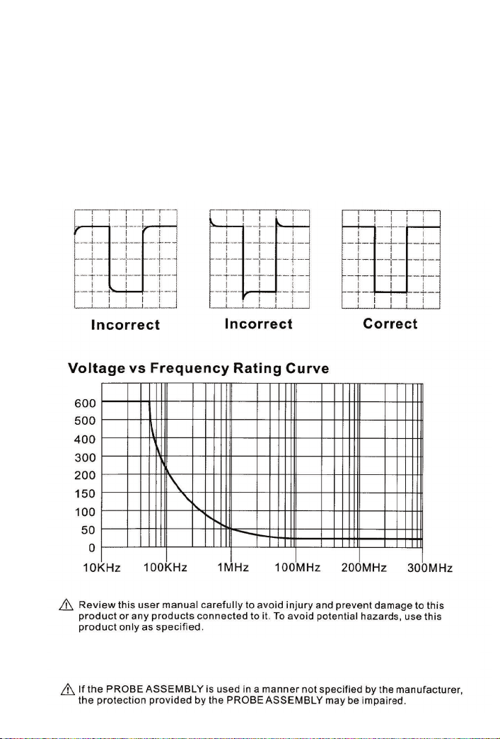
Frequency Compensation
Before taking any measurements using a probe, first check the
compensation of the probe and adjust it to match the channel inputs.
Most oscilloscopes have a square wave reference signal available at a
terminal on the front panel used to compensate the probe.
Connect the probe to this terminal or another 2 V pk-pk, 1 kHz
square wave source.. Set the probe to 10X position. Adjust trimmer
until seeing flat-top square wave on the display.
Vpk-pk
Page 3
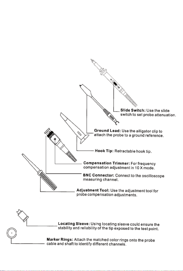
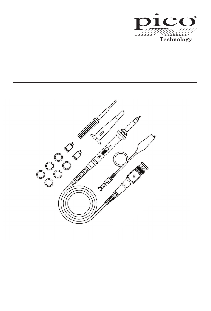
Accessories and Features
MI007 is provided with several accessories designed to make
probing and measurement simpler. Please take a moment to
familiarize yourself with these accessories and their uses.
Page 4

Probe Characteristics
Attenuation Ratio 1X 10X
Bandwidth 15 MHz 60 MHz
Rise Time 23.3 ns 5.8 ns
Input Resistance 1 MΩ ± 2% 10 MΩ ± 2%
~
Input Capacitance 70pF
120pF 14pF~18pF
Maximum Working Voltage (CAT I) 200 V pk-pk 600 V pk-pk
Compensation Range 15 - 45pF
Operation Environment 0 - 50°C, 0 - 80%RH
Storage Environment -20 - 60°C, 0 - 90%RH
Size 110 ±2cm
Weight About 55g
Accessory Kit
MI007 TA208
Description 1PC 2PC
Retractable Hook Tip 1 2
Adjustment Tool 1
Locating Sleeve 2
Marker Rings 6
Ground Lead 1 2
DO238-4
© Copyright 2014 Pico Technology Ltd. All rights reserved.
 Loading...