

Page 1
Installation and
Operation Manual
VSM-3/4S
Audio-Video with Super Video RF Modulator
Operation
Manual
Rev. 05/03
Ph:800-421-6511
www.picomacom.com
Page 2
VSM-3/4S
2
Rev. 05/03
Ph:800-421-6511
www.picomacom.com
The lightning flash with arrowhead symbol, within an
equilateral triangle, is intended to alert the user to the
presence of un-insulated “dangerous voltage” within the
product’s enclosure that may be of sufficient magnitude
to constitute a risk of electric shock to persons.
The exclamation point within an equilateral triangle is
intended to alert the user to the presence of important
operating and maintenance (servicing) instructions in
the literature accompanying the appliance.
Product Inspection
Inspect the equipment for shipping damage. Should any damage be discovered, immediately file a claim with the carrier.
Important Safety Instructions
To insure proper installation and operation, take a moment to read this guide before proceeding with the installation. If you have any questions
or comments about the VSM-3/4S RF Modulator, please contact your dealer or have him contact the PICO MACOM Service Center at these
phone numbers: 800-421-6511, 818-493-4300.
1. Read Instructions: All safety and operating instructions should
be read before the appliance is operated.
2. Retain Instructions: The safety and operating instructions
should be retained for future reference.
3. Heed Warnings: All warnings on the appliance should be
adhered to.
4. Follow Instructions: All operating and user instructions should
be followed.
5. Cleaning: Unplug this appliance from the wall outlet before cleaning. Use a damp cloth for cleaning. Do not use liquid cleaners or
aerosol cleansers.
6. Do Not Use Attachments: Use of attachments not recommended
by the manufacturer may cause hazards.
7. Water and Moisture: Do not use this product near water—for
example, near a bathtub, washbowl, kitchen sink, laundry tub, in a wet
basement, or near a swimming pool—and the like.
8. Accessories: Do not place this product on an unstable cart,
stand, tripod, bracket, or table. The product may fall, causing serious
injury to a child or adult, and serious damage to the appliance.
9. Ventilation: This video product should never be placed near or
over a radiator or heat register. This video product should not be
placed in a built-in installation such as a bookcase or rack unless
proper ventilation is provided or the manufacturer’s instructions have
been adhered to. Any slots or opening in the cabinet are provided for
ventilation. To ensure reliable operation of the video product and to
protect it from overheating, these openings must not be blocked or
covered. Openings should never be blocked by placing the product on
a bed, sofa, rug, or other similar surface.
10. Grounding or Polarization: This video product is equipped with
a three-pin molex type plug for 5 and 12Vdc use. It is to be inserted
into only the type of receptacle for which it is specifically designed.
WARNING: TO REDUCE THE RISK OF FIRE OR ELECTRIC SHOCK, DO NOT EXPOSE THIS
APPLIANCE TO RAIN OR MOISTURE. DO NOT OPEN THE CABINET.
REFER SERVICING TO QUALIFIED PERSONNEL ONLY
.
CAUTION: TO PREVENT ELECTRIC SHOCK DO NOT USE THIS (POLARIZED) PLUG WITH AN
EXTENSION CORD RECEPTACLE OR OTHER OUTLET UNLESS THE BLADES CAN BE
FULLY INSERTED TO PREVENT BLADE EXPOSURE.
ATTENCION: POUR PREVENIR LES CHOCS ELECTRIQUES, NE PAS UTILISER CETTE FICHE POLARISEE AVEC
UN PROLONGATEUR, UNE PRISE DE COURANT OU UNE AUTRE SORTIE DE COURANT, SAUF SI
LES LAMES PEUVENT ETRE INSEREES A FOND SANS EN LAISSER AUCUNE PARTIE A DECOUVERT.
Safeguards
Page 3
VSM-3/4S
3
Rev. 05/03
Ph:800-421-6511
www.picomacom.com
Safeguards
11. Power Sources: This product should be operated only from the
type of power source indicated on the marking label. If you are not
sure of the type of power supplied to your home, consult your appliance dealer or local power company.
12. Power-cord Protection: Power-supply cords should be routed
so they are not likely to be walked on or pinched by items placed upon
or against them. Pay particular attention to cords and plugs, convenience receptacles, and the point where they exit from the appliance.
13. Lightning: For added protection for this product during a lightning
storm, or when it is left unattended or unused for long periods of time,
the unit should be disconnected from power source.
14. Power Lines: An outside antenna system should not be located
in the vicinity of overhead power lines, other electric light or power circuits, where it can fall into such power lines or circuits. When installing
an outside antenna system, extreme care should be taken to keep
from touching such power lines or circuits as contact with them may
be fatal.
15. Overloading: Do not overload wall outlets and extension cords as
this can result in risk of fire or electric shock.
16. Object and Liquid Entry: Never push objects of any kind into this
product through openings as they may touch dangerous voltage
points or short-out parts that could result in a fire or electric shock.
Never spill liquid of any kind on the product.
17. Servicing: Do not attempt to service this product yourself as
opening or removing covers may expose you to dangerous voltage or
other hazards. Refer all servicing to qualified service personnel.
18. Damage Requiring Service: Unplug this product from the wall
outlet and refer servicing to qualified service personnel under the
following conditions:
a. When the power-supply cord or plug is damaged.
b. If liquid has been spilled, or objects have fallen into the product.
c. If the product has been exposed to rain or water.
d. If the product does not operate normally by following the oper-
ating instruction. Adjust only those controls that are covered by
the operating instructions. An improper adjustment may result in
damage and will often require extensive work by a qualified technician to restore the product to its normal operation.
e. If the product has been dropped or the cabinet has been
damaged.
f. When the product exhibits a distinct change in performance—
this indicates a need for service.
19. Replacement Parts: When replacement parts are required, be
sure the service technician has used replacement parts specified by
the manufacturer or have the same characteristics as the original
parts. Unauthorized substitutes may result in fire, electric shock or
other hazards.
20. Safety Check: Upon completion of any service or repairs to this
product, ask the service technician to perform safety checks to determine that the product is in proper operating conditions.
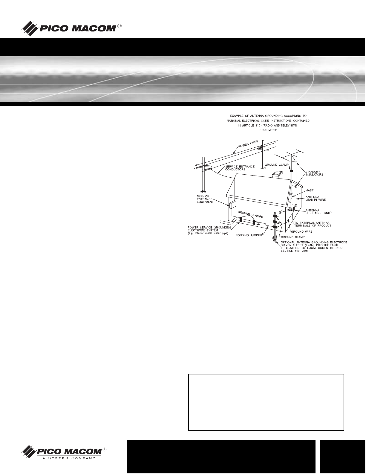
21. Outdoor Antenna Grounding: Before attempting to install this
product, be sure the antenna or cable system is grounded so as to
provide some protection against voltage surges and built-up static
charges.
a. Use No.10 AWG (5.3mm) copper, No.8 AWG (8.4mm)
aluminum, No.7 AWG (10mm) copper-clad steel or bronze
wire or larger, as ground wire.
b. Secure antenna lead-in and ground wires to house with standoff insulators spaced from 4 feet (1.22m) to 6 feet (1.83m) apart.
c. Mount antenna discharge unit as close as possible to where
lead-in enters house.
d. A driven rod may be used as the grounding electrode where
other types of electrode systems do not exist. Refer to the
National Electrical Code, ANSI/NFPA 70-1984 for information.
e. Use jumper wire not smaller than No.6 AWG (13.3mm) copper
or equivalent, when a separate antenna grounding electrode
is used.
NOTE TO THE CATV SYSTEM INSTALLER
THIS REMINDER IS PROVIDED TO CALL THE CATV SYSTEM
INSTALLER’S ATTENTION TO ARTICLE 820-22 OF THE NEC
THAT PROVIDES GUIDELINES FOR PROPER GROUNDING
AND, IN PARTICULAR, SPECIFIES THAT THE CABLE
GROUND SHALL BE CONNECTED TO THE GROUNDING
SYSTEM OF THE BUILDING, AS CLOSE TO THE POINT OF
CABLE ENTRY AS PRACTICAL.
Page 4

VSM-3/4S
Descriptions
The VSM-3/4S VIDEO RF MODULATOR WITH S-VHS INPUT is a single channel
audio/video signal modulator that is designed to convert the separate audio and
video signals from various video components such as video cameras, VCRs, DVD
Players, or game consoles into a single VHF signal appropriate for viewing on
most television sets. The unit also provides inputs for your S-VHS and antenna or
cable TV signals to pass through to the output. When a video signal from your
video component is present, the unit will bypass the cable/antenna input and allow
the signal from you component to be viewed on channel 3 or 4. When your video
component is not being used (there is no signal present) the unit allows for normal
viewing of your cable/antenna signal.
Audio-Video with Super Video RF Modulator
VSM-3/4S
Low-cost channel 3/4
auto switching A/V
Modulator connects DVD,
VCR, Satellite, Security video, or
other Video Equipment to standard TV sets with F-type RF only
input connectors
F-type RF Connectors
RCA-type A/V Baseband
Connectors
Rear Panel Channel 3 or 4
Selection Switch Insertion loss
4.5dB
RF Output Impedance 75-Ohms
Audio Input Impedance
13K+3KOhms
Video Input Impedance 1KOhm
switchable
Power Requirements 120V 60Hz 5W
Dimensions 5-7/8˝(L) x 3˝(D) x 1-3/8˝(H)
Weight 0.8 lbs
Audio-Video with Super Video RF Modulator
4
Rev. 05/03
Ph:800-421-6511
www.picomacom.com
Page 5

VSM-3/4S
Specifications
5
Rev. 05/03
Ph:800-421-6511
www.picomacom.com
Audio-Video with Super Video RF Modulator
Output Channels: 3 or 4
Output Impedance: 75 Ohms
Input Impedance: 75 or 1k Ohms
TV to ANT Insertion Loss: 50-806MHz: -2dB
Video Carrier Output Level: 69dBµV
Power Requirements: 120VAC, 60Hz, 4.5W
Operating Temperature: -10° C to +50° C
Dimensions: 5
13
/16˝(W) x 31/16˝(D) x 17/16˝(H)
(148 x 78 x 37 mm)
Weight: 1lb 2.5oz (.524kg)
NOTE: Complies with Part 155 FCC rules
UL Listed TV Accessory
Audio Input Impedance: 13±3k Ohms
RF
Video
Audio
General
Ordering Information
VSM-3/4S Audio-Video with Super Video RF Modulator
Page 6

VSM-3/4S
6
Rev. 05/03
Ph:800-421-6511
www.picomacom.com
Operation and Controls
1. Tu rn the power on to both your television and your video component.
2. Tu rn both your TV and the RF Modulator to the same channel (3 or 4, whichever gives you the clearest pic-
ture) using the switch in the back of the modulator.
3. Set the OHMS switch on the back of the modulator to 75 or 1K; whichever gives you the clearest picture. The
1K setting is recommended for video-game consoles; the 75 setting is recommended for all other applications.
4. The light on the front of the RF Modulator will turn on when it is receiving a video signal from your video
component. The video signal can be viewed on channel 3 or 4 (whichever you selected in step #1).
If the light is not on, either:
a. Your video component is not sending a signal (not turned on, not playing, etc.).
b. The RF Modulator and your video component are not connected properly, check
all your connections.
Operation
Page 7

VSM-3/4S
7
Rev. 05/03
Ph:800-421-6511
www.picomacom.com
Installation Procedure
1. Connect your existing Cable or Antenna cable to the “ANT-IN” port on the modulator.
NOTE: If you have a flat type antenna wire you will need the appropriate transformer.
2. Connect the modulator’s “TO-TV” port to your television using a standard 75-Ohm Coaxial Cable.
NOTE: If your TV is not cable-ready you will need to install the appropriate transformer.
3. Connect your Video Component’s video and audio output jacks to the RF Modulator's corresponding “Video”, “Audio L”, and
“Audio R” using the appropriate Audio/Video Patch Cord or Audio/Video/S-VHS Patch Cord. Most Audio/Video Patch Cords
are color coded for ease of installation.
4. Connect the modulator’s AC power cable to an existing 120VAC power receptacle.
Installation
1
Existing
coaxial cable
to antenna
Existing
flat cable
to antenna
*Transformer
*Not Included
Note:
Accessories necessary for proper
installation may
be obtained from
your retailer.
*Coaxial Cable
*Transformer
*Coaxial Cable
RF Modulator RF Modulator
*
Video Patch
Cord
*S-VHS
Audio-Video
Cable
RF Modulator
Your Video Component
DVD/VCR–Game System–Camcorder
Your Video Component
with S-Video
2
3
Page 8

VSM-3/4S
8
Rev. 05/03
Ph:800-421-6511
www.picomacom.com
Warranty
Limited Warranty
Pico Macom warrants to the original purchaser that all of its new products are of sound design, quality materials and workmanship at the time of manufacture
and will be free from related defects for one year from the original purchase date. Pico Macom will repair or, at its discretion, replace without cost to the original
purchaser, the product which, upon inspection by Pico Macom, appears to be defective or not conforming to factory specifications. Pico Macom will cover the cost
of parts, labor, and return freight from factory.
Five-Year Limited Warranty
Most products designated as “Headend Electronics” are further covered by an extended 4-year period beyond the expiration of the original 1-year warranty, for a full
5-year period. Qualified equipment requiring factory repair during the extended 4-year period is covered under our re-certification program. Re-certification fees
under this program shall not to exceed 20% of the product’s List Price and whenever possible, Pico Macom will attempt to upgrade performance to the latest
improved specification.
Warranty Limitations
This warranty excludes coverage of damage or inoperability resulting from (1) use or installation other than in strict accordance with Pico Macom’s written instructions, (2) disassembly or repair by someone other than Pico Macom or a Pico Macom authorized repair center, (3) misuse, misapplication or abuse, (4) alteration,
(5) lack of reasonable care or (6) wind, ice, snow, rain, lightning, power surges, or any other weather conditions or acts of God. Pico Macom’s warranty with respect
to third-party proprietary sub-assembly modules and/or private-label products are limited to the duration and terms of third-party vendors’ warranty. Pico Macom
shall in no event and under no circumstances be liable or responsible for any consequential, indirect, incidental, punitive, direct or special damages based upon
breach of warranty, breach of contract, negligence, strict tort liability or otherwise or any other legal theory, arising directly or indirectly from the sale, use, installation or failure of any product acquired by buyer from Pico Macom. This limited warranty extends to the original purchaser. Pico Macom reserves the right to modify
or discontinue this warranty at Pico Macom’s sole discretion without notification. No other warrantees are expressed or implied.
Uptime Loaner Program
Our Uptime loaner program is designed to provide domestic users of our headend products and commercial systems the best possible support and service. This
program is established to minimize downtime resulting from equipment failure in critical service situations. We offer this program free-of-charge (excluding freight)
to qualified purchasers within the warranty period. The program provides a free equipment loan of like qualified equipment enabling seamless operation for the time
required to repair and return the unit.
The process is simple. Call our Customer Service desk requesting a return-merchandise-authorization (RMA) number for the failed equipment and ask for a loaner
unit. We will issue an invoice for the List Price of the loaner unit plus shipping costs. When you receive the loaner unit, pack the failed unit in the loaner unit’s box
and ship it freight prepaid to Pico Macom for repair. When you receive the repaired unit, a new RMA number will be provided in the box. Carefully pack the loaner
unit and affix the new RMA number on the box and ship it back to us for full credit excluding shipping costs.
To qualify for the program, you must have current open-terms with us and in good standing. We must receive your failed unit within one week after the loaner unit
is shipped to you, and must likewise receive the loaner unit within one week after the repaired unit is shipped back to you. Daily rental fees not to exceed 10% of
the equipment’s List Price will apply beyond one week after the loaner or repaired unit are shipped to you. Other limitations may apply, so please call us for additional information on qualifying equipment and procedures. Pico Macom reserves the right to modify or discontinue the Uptime Loaner Program at any time, and at
its sole discretion.
Damage or Shortage Claims
Our shipping staff carefully packs and ships your orders in compliance with common carriers’ requirements. Please make note of any obvious damage or shortage
on the freight bill or carrier’s receipt next to your signature. The carrier’s agent must too sign acknowledging the loss. Failure to do so may result in the carrier’s
refusal to honor the claim. Please open your order immediately upon receipt to check for concealed damage and compare the packing list to the items shipped. If
damaged, keep the original shipping cartons for possible inspection by the carrier.You must report claims for loss or damage within 3 days of delivery, while claims
for erroneous charges or price corrections must be presented within 30 days of invoice date.
Returning Shipped Items
To return any shipped items, including those shipped for warranty repairs or credit, call our Customer Service desk to request a Return Merchandise Authorization
(RMA) number. Please reference the original invoice number and purchase date, and product serial number (if any). Be certain to mark the RMA number on the
package boldly and legibly. Unless we specify a different carrier, please ship your returned items to us via UPS freight prepaid and fully insured. If returned for
credit, we will promptly process your request upon receipt of your return order.
Our Return Policy: Your Satisfaction Guaranteed
Our goal is your complete satisfaction. If for any reason, our products were not quite what you anticipated, simply call your customer service rep and
we will be happy to assist you in replacing or returning the order.You may return current, non-discontinued items for full credit for up to 30 days from
invoice date. Our requirements are simple: Excepting defective items, the products must be returned in their original packaging and in re-salable
condition. Restocking fees may otherwise apply beyond this period or if products are not returned in their original condition. Please contact your
customer service rep for more information.
 Loading...