

Page 1
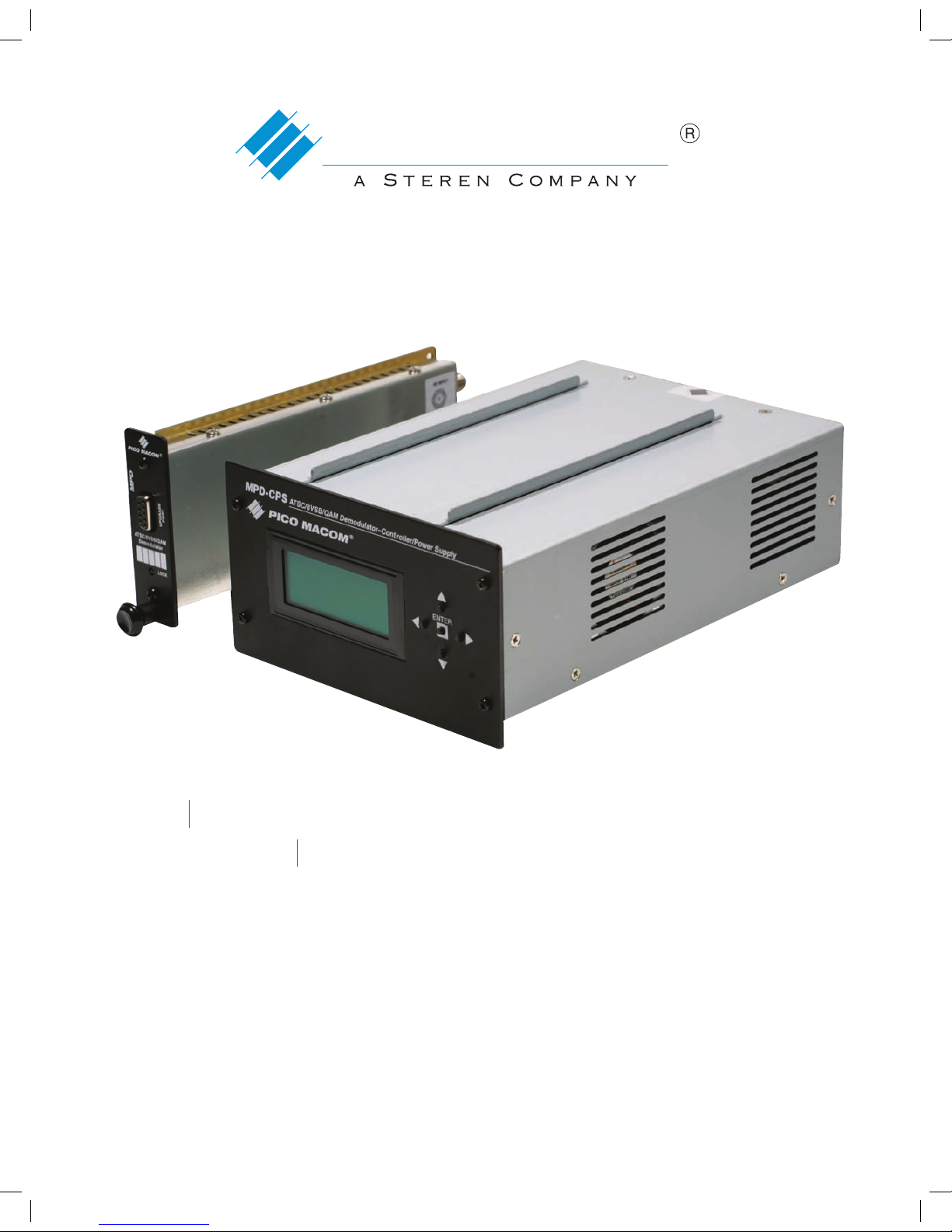
MPD and MPD-CPS Owners Manual
PICO MACOM
Please read this manual thoroughly before use.
Keep this manual handy for future reference.
MPD ATSC/8VSB/QAM Demodulator
MPD-CPS ATSC/8VSB/QAM Demodulator-Controller/Power Supply
Visit Our Web-Site www.picomacom.com
Contact Us 858.546.5050
Toll Free 800.421.6511
MPD Owners Manual.indd 1 5/8/08 4:50:34 PM
Page 2

2
CONTACT US TOLL FREE 800-421-6511
www.picomacom.com
PICO MACOM
MPD
ATSC/8VS B/QAM Dem odulator
MPD-CPS
Controller/Power Supply
Product Inspection
Inspect the equipment for shipping damage. Should any damage be discovered, immediately file a claim with the carrier.
Important Safety Instructions
To ensure proper installation and operation, take a moment to read this guide before proceeding with the installation. If you have
any questions or comments about the MPD ATSC/8VSB/QAM Demodulator, please contact your dealer or have him contact the
PICO MACOM Service Center at these phone numbers: 800-421-6511, 818-493-4300.
Pico Macom
MPD ATSC/8VSB/QAM Demodulator &
MPD-CPS Controller/Power Supply
OWNERS MANUAL
The lightning flash with arrowhead symbol, within an equilateral
triangle, is intended to alert the user to the presence of uninsulated “dangerous voltage” within the product’s enclosure that may
be of sufficient magnitude to constitute a risk of electric shock to
persons.
The exclamation point within an equilateral triangle is intended to
alert the user to the presence of important operating and maintenance (servicing) instructions in the literature accompanying the
appliance.
WARNING: TO REDUCE THE RISK OF FIRE OR ELECTRIC SHOCK, DO NOT EXPOSE THIS APPLIANCE
TO RAIN OR MOISTURE. DO NOT OPEN THE CABINET.
REFER SERVICING TO QUALIFIED PERSONNEL ONLY.
CAUTION: TO PREVENT ELECTRIC SHOCK DO NOT USE THIS (POLARIZED) PLUG WITH AN
EXTENSION CORD RECEPTACLE OR OTHER OUTLET UNLESS THE BLADES CAN BE
FULLY INSERTED TO PREVENT BLADE EXPOSURE.
ATTENCION: POUR PREVENIR LES CHOCS ELECTRIQUES, NE PAS UTILISER CETTE FICHE POLARISEE
AVEC UN PROLONGATEUR, UNE PRISE DE COURANT OU UNE AUTRE SORTIE DE COURANT,
SAUF SI LES LAMES PEUVENT ETRE INSEREES A FOND SANS EN LAISSER AUCUNE PARTIE A
DECOUVERT.
1. Read Instructions: All safety and operating instructions
should be read before the appliance is operated.
2. Retain Instructions: The safety and operating
instructions should be retained for future reference.
3. Heed Warnings: All warnings on the appliance
should be adhered to.
4. Follow Instructions: All operating and user instructions should be followed.
5. Cleaning: Unplug this appliance from the wall outlet before cleaning. Use a damp cloth for cleaning. Do not use
liquid cleaners or aerosol cleansers.
6. Do Not Use Attachments: Use of attachments not recommended by the manufacturer may cause hazards.
7. Water and Moisture: Do not use this product near water—
for example, near a bathtub, washbowl, kitchen sink, laundry tub, in a wet basement, or near a swimming pool—and
the like.
8. Accessories: Do not place this product on an unstable cart,
stand, tripod, bracket, or table. The product may fall, causing serious injury to a child or adult, and serious damage to
the appliance.
9. Elevated Operating Ambient: If installed in a closed or multiunit rack assembly, the operating ambient temperature of the
rack environment may be greater than room ambient. Therefore, consideration should be given to installing the equipment
in an environment compatible with the maximum ambient
temperature (Tma) specified by the manufacturer.
10. Reduced Air Flow: Installation of the equipment in a rack
should be such that the amount of air flow required for safe
operation of the equipment is not compromised.
11. Mechanical Loading: Mounting of the equipment in the
rack should be such that a hazardous condition is not achieved
due to uneven mechanical loading.
12. Circuit Overloading: Consideration should be given to
the connection of the equipment to the supply circuit and the
MPD Owners Manual.indd 2 5/8/08 4:50:35 PM
Page 3
3
CONTACT US 858.546.5050
www.picomacom.com
PICO MACOM
MPD
ATSC/8VS B/QAM Dem odulator
MPD-CPS
Controller/Power Supply
effect that overloading of the circuits might have on overcurrent protection and supply wiring. Appropriate consideration of
equipment nameplate ratings should be used when addressing
this concern.
13. Reliable Earthing: Reliable earthing of rack-mounted
equipment should be maintained. Particular attention should
be given to supply connections other than direct connections
to the branch circuit (e.g. use of power strips).
14. Power Sources: This product should be operated only from
the type of power source indicated on the marking label. If
you are not sure of the type of power supplied to your home,
consult your appliance dealer or local power company.
15. Power-cord Protection: Power-supply cords should be routed so they are not likely to be walked on or pinched by items
placed upon or against them. Pay particular attention to cords
and plugs, convenience receptacles, and the point where they
exit from the appliance.
16. Lightning: For added protection for this product during a
lightning storm, or when it is left unattended or unused for long
periods of time, the unit should be disconnected from power
source.
17. Power Lines: An outside antenna system should not be
located in the vicinity of overhead power lines, other electric
light or power circuits, where it can fall into such power lines
or circuits. When installing an outside antenna system, extreme
care should be taken to keep from touching such power lines
or circuits as contact with them may be fatal.
18. Object and Liquid Entry: Never push objects of any kind
into this product through openings as they may touch dangerous voltage points or short-out parts that could result in a fire or
electric shock. Never spill liquid of any kind on the product.
19. Servicing: Do not attempt to service this product yourself
as opening or removing covers may expose you to dangerous
voltage or other hazards. Refer all servicing to qualified service
personnel.
20. Damage Requiring Service: Unplug this product from the
wall outlet and refer servicing to qualified service personnel
under the following conditions:
a. When the power-supply cord or plug is damaged.
b. If liquid has been spilled, or objects have fallen into
the product.
c. If the product has been exposed to rain or water.
d. If the product does not operate normally by follow ing the operating instruction. Adjust only those con trols that are covered by the operating instructions.
An improper adjustment may result in damage and
will often require extensive work by a qualified tech nician to restore the product to its normal operation.
e. If the product has been dropped or the cabinet has
been damaged.
f. When the product exhibits a distinct change in perfor mance—this indicates a need for service.
21. Replacement Parts: When replacement parts are required,
be sure the service technician has used replacement parts
specified by the manufacturer or have the same characteristics
as the original parts. Unauthorized substitutes may result in
fire, electric shock or other hazards.
22. Safety Check: Upon completion of any service or repairs
to this product, ask the service technician to perform safety
checks to determine that the product is in proper operating
conditions.
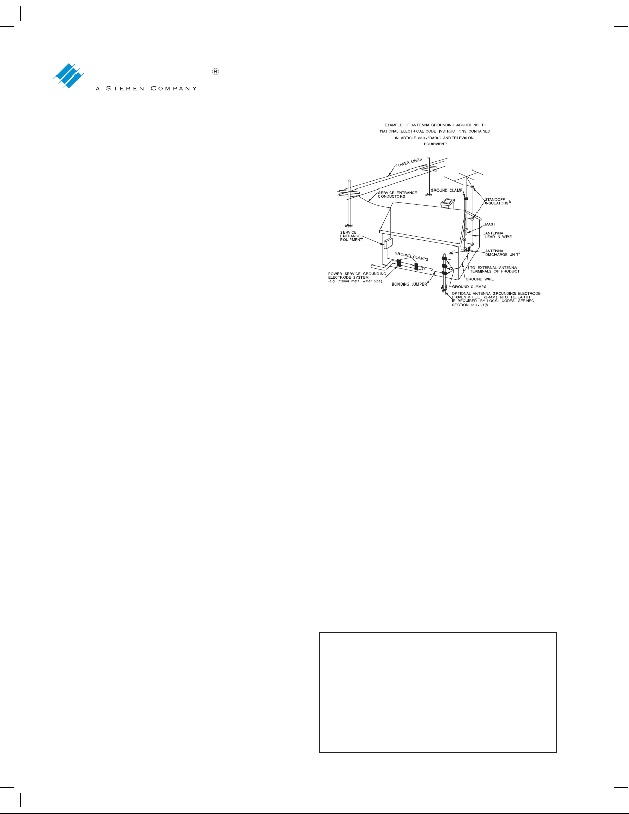
23. Outdoor Antenna Grounding: Before attempting to install
this product, be sure the antenna or cable system is grounded
so as to provide some protection against voltage surges and
built-up static charges.
a. Use No.10 AWG (5.3mm) copper, No.8 AWG
(8.4mm) aluminum, No.7 AWG (10mm) copper-clad
steel or bronze wire or larger, as ground wire.
b. Secure antenna lead-in and ground wires to house
with stand-off insulators spaced from 4 feet (1.22m) to
6 feet (1.83m) apart.
c. Mount antenna discharge unit as close as possible to
where lead-in enters house.
d. A driven rod may be used as the grounding electrode
where other types of electrode systems do not exist.
Refer to the National Electrical Code, ANSI/NFPA 70 1984 for information.
e. Use jumper wire not smaller than No.6 AWG
(13.3mm) copper or equivalent, when a separate
antenna grounding electrode is used.
NOTE TO THE CATV SYSTEM INSTALLER
THIS REMINDER IS PROVIDED TO CALL THE CATV SYSTEM INSTALLER’S ATTENTION TO ARTICLE 820-22 OF
THE NEC THAT PROVIDES GUIDELINES FOR PROPER
GROUNDING AND, IN PARTICULAR, SPECIFIES THAT
THE CABLE GROUND SHALL BE CONNECTED TO THE
GROUNDING SYSTEM OF THE BUILDING, AS CLOSE
TO THE POINT OF CABLE ENTRY AS PRACTICAL.
MPD Owners Manual.indd 3 5/8/08 4:50:37 PM
Page 4
4
CONTACT US TOLL FREE 800-421-6511
www.picomacom.com
MPD
ATSC/ 8VSB/QAM De mo dulator
PICO MACOM
• Decodes 8VSB, 64 QAM and 256 QAM (Annex B)
digital RF signals in the frequency range 54 to 860 MHz.
• High Density design, up to 10 MPD modules in 2 RU.
• Stereo Output.
• Front panel indicator LED to monitor input 8VSB or
QAM signal lock.
• Easily configured power controller allows individual
channel mapping and automatic scanning of individual
modules.
• Convenient front panel channel selection for channel
and demodulation mode settings.
Fe at ures
• Equipped with short and long equalizer taps to
eliminate multi-path effects.
• Decodes all 18 ATSC video formats.
• Input voltage between 90-260Vac.
• Supports IRC and HRC offsets.
• One F-connector video output and two stereo RCA left and
right audio outputs provided at the back of the unit.
• Extremely low power consumption
• Nonvolatile memory for easy channel recall in the event of
power failure
T
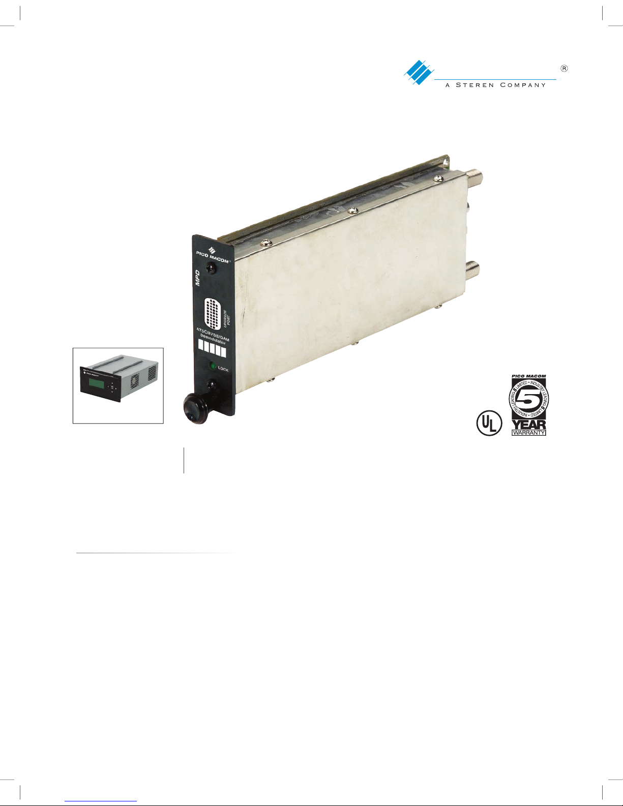
he Pico Macom MPD demodulator provides a cost-effective solution for digital-to-analog conversion. The MPD will accept
an 8VSB or unencrypted QAM digital RF signal and convert it to baseband video and left and right stereo audio outputs. The
MPD demodulator can receive all of the 18 ATSC video formats, including HD video, and convert them for display on both
analog and digital television sets.
MPD
ATSC/ 8VSB/QAM De mo dulator
®
C
MPD-CPS
Requires Power Supply/Controller
(Sold Separately)
MPD Owners Manual.indd 4 5/8/08 4:50:47 PM
Page 5
5
CONTACT US 858.546.5050
www.picomacom.com
PICO MACOM
MPD
ATSC/8VSB/QAM Demodulator
5
CONTACT US 858.546.5050
www.picomacom.com
PICO MACOM
MPD
ATSC/8VSB/QAM Demodulator
Specifications Subject to Change © 2008 Pico Macom, Inc.
MPD
Input - QAM
Mode: 64 & 256 QAM Annex B
Data rate: 26.9 Mbps QAM 64
38.8 Mbps QAM 256
Input connector: 75 ohm F-female
Frequency range: 54 to 860 MHz
Channel range: Ch. 2 - 135
Input AGC range: -35 to 30dBmV
Impedance: 75 ohm
Input connector: F-female
Input - 8VSB
Frequency range: 54 to 806 MHz
Channel range: VHF Ch. 2 - 13, UHF 14 - 69
Data rate: 19.4 Mbps
Input AGC range: -35 to 30dBmV
Modulation: 8VSB
Impedance: 75 ohm
Input connector: F-female
Output - Video NTSC
Frequency range: DC to 4.2 MHz
Output level: 1 V p-p
Impedance: 75 ohm
Video format: 4801 NTSC
Aspect ratio: 4:3, 16:9 (PAN, SCAN)
Specifications
Front View
MPD
LOCK
PICO MACOM
UPGRADE
PORT
ATSC/8VSB/QA M
Demodula tor
VIDEO OUT
RF INPUT
AUDIO
OUT
LEFT
RIGHT
DATA
PWR
Side View Back View
Output - Analog Stereo Audio
Audio level: 1 V p-p
Audio control: Adjustable
Frequency range: 50Hz to 19kHz
Connectors: RCA, left and right
General
DC input voltage: 5 and 12 Vdc
MPD Power: 5Vdc @ 300mA
12Vdc @ 200mA
Dimensions: 1.025”W x 3.465”H x 8.70”D
Weight: 0.8 lbs.
MPD-CPS
Input: 100-240Vac, 50/60Hz, 2.0A max.
Output: +5Vdc, 4.5A max.; +12Vdc, 3.0A max.
Dimensions: 6.2”W x 9.05”D x 3.47”H
Weight: 4 lbs.
Ordering Information
MPD - ATSC/8VSB/QAM Demodulator
MPD-CPS - Power Supply/Controller
MPC-12C - Mini-Mod Chassis
MOR-CS - Cooling Fan System
PHC-12G - 12 Channel (Passives Headend Combiner)
MPD-CPS
®
ENTER
ATSC/8VSB/QAM Demodulator–Controller/Power Supply
MPD
LOCK
PICO MACOM
UPGRADE
PORT
ATSC/8VSB/QAM
Demodulator
MPD
LOCK
PICO MACOM
UPGRADE
PORT
ATSC/8VSB/QAM
Demodulator
MPD
LOCK
PICO MACOM
UPGRADE
PORT
ATSC/8VSB/QAM
Demodulator
MPD
LOCK
PICO MACOM
UPGRADE
PORT
ATSC/8VSB/QAM
Demodulator
MPD
LOCK
PICO MACOM
UPGRADE
PORT
ATSC/8VSB/QAM
Demodulator
MPD
LOCK
PICO MACOM
UPGRADE
PORT
ATSC/8VSB/QAM
Demodulator
MPD
LOCK
PICO MACOM
UPGRADE
PORT
ATSC/8VSB/QAM
Demodulator
MPD
LOCK
PICO MACOM
UPGRADE
PORT
ATSC/8VSB/QAM
Demodulator
MPD
LOCK
PICO MACOM
UPGRADE
PORT
ATSC/8VSB/QAM
Demodulator
MPD
LOCK
PICO MACOM
UPGRADE
PORT
ATSC/8VSB/QAM
Demodulator
MPD-CPS
MPC-12C
MPD
--Pico--
--MPD--
MPD Owners Manual.indd 5 5/8/08 4:50:50 PM
Page 6

6
CONTACT US TOLL FREE 800-421-6511
www.picomacom.com
PICO MACOM
MPD
ATSC/8VS B/QAM Dem odulator
MPD-CPS
Controller/Power Supply
Table of Contents
Installation - Rack ............................................................................................................................................... 7
Front View .......................................................................................................................................................... 7
Rear View - Electrical Connections .................................................................................................................... 7
Programming Set-Up .......................................................................................................................................... 9
Volume Control Programming .......................................................................................................................... 12
TV Mode Programming - 8VSB or QAM ........................................................................................................... 12
Module Replacement ....................................................................................................................................... 14
1. Power Supply / Controller ............................................................................................................... 14
2. Module ........................................................................................................................................... 14
Operation and Care - Do’s & Don’ts ................................................................................................................. 14
System Congigurations ..................................................................................................................................... 15
WARRANTY ..................................................................................................................................................... 17
MPD Owners Manual.indd 6 5/8/08 4:50:51 PM
Page 7
7
CONTACT US 858.546.5050
www.picomacom.com
PICO MACOM
MPD
ATSC/8VS B/QAM Dem odulator
MPD-CPS
Controller/Power Supply
INSTALLATION - Rack
It is recommended that assistance be available to safely install equipment in equipment racks. Chassis must be fastened securely in equipment
rack before populating with modules.
1. Install chassis in equipment rack (equipment rack sold separately) by supporting the bottom and rear of
chassis at the desired elevation in rack.
2. Line up the side holes of chassis with the tapped equipment rack holes.
3. Insert the provided screws through the side holes in chassis and thread into the tapped equipment
rack holes.
4. Fasten the bottom screws first, fasten top screws, tighten securely.
5. Slide MPD-CPS power supply/controller and MPD modules into chassis.
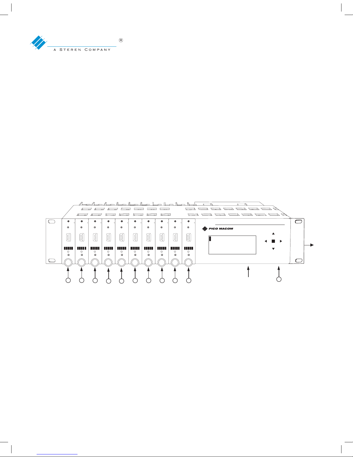
Front View
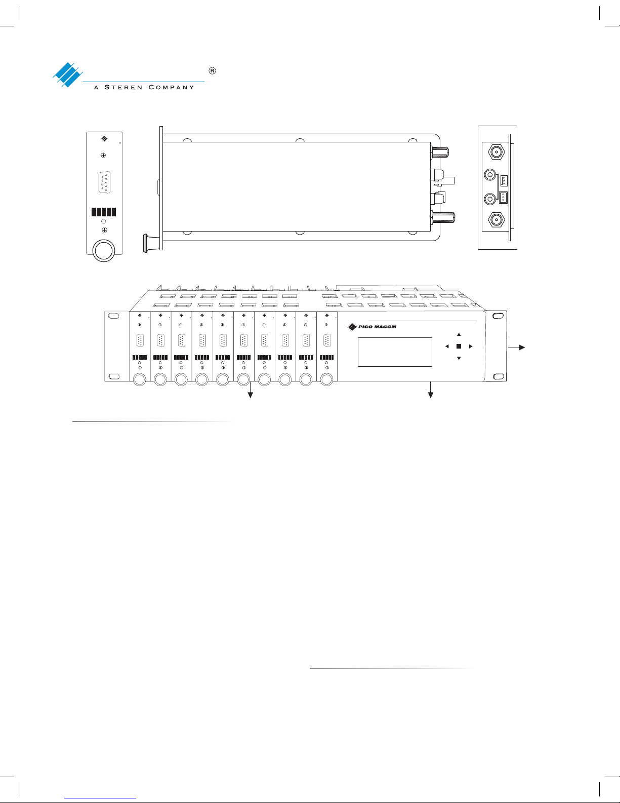
Picture shows the module sequence number and the control unit (figure 1).
(figure 1).
Rear View – Electrical Connections
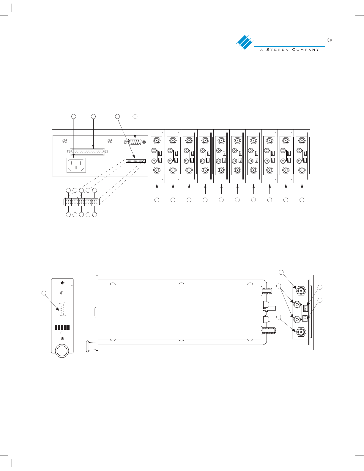
1. Connect the D-Sub 37-pin power cable to the MPD-CPS (fig.2-item#12).
2. Connect the 30-pin data cable to the MPC-CPS (fig.2-item 13)
3. Module power and communication connection:
a. Connect power cable from power connector to each of the module power inputs (fig.3-item 5).
b. Connect COMM lines to each of the modules, in the proper sequence, according to the
picture below. COMM line 1 to module 1, COMM line 2 to module 2, to COMM line 3
to module 3 etc. (fig.3-item 6).
4. Connect the AC power cable to the MPD-CPS (fig. 2-item 11).
5. RF connections:
a. Connect RF input to the MPD (fig.3-item 4).
b. Connect video (fig.3-item 2) and audio outputs (fig.3-items 3) to a modulator
12345
67
8
910
11
MPC-CPS
MPD-CPS
®
ENTER
ATSC/8VSB/QAM Demodulator–Controller/Power Supply
MPD
LOCK
PICO MACOM
UPGRADE
PORT
ATSC/8VSB/QAM
Demodulator
MPD
LOCK
PICO MACOM
UPGRADE
PORT
ATSC/8VSB/QAM
Demodulator
MPD
LOCK
PICO MACOM
UPGRADE
PORT
ATSC/8VSB/QAM
Demodulator
MPD
LOCK
PICO MACOM
UPGRADE
PORT
ATSC/8VSB/QAM
Demodulator
MPD
LOCK
PICO MACOM
UPGRADE
PORT
ATSC/8VSB/QAM
Demodulator
MPD
LOCK
PICO MACOM
UPGRADE
PORT
ATSC/8VSB/QAM
Demodulator
MPD
LOCK
PICO MACOM
UPGRADE
PORT
ATSC/8VSB/QAM
Demodulator
MPD
LOCK
PICO MACOM
UPGRADE
PORT
ATSC/8VSB/QAM
Demodulator
MPD
LOCK
PICO MACOM
UPGRADE
PORT
ATSC/8VSB/QAM
Demodulator
MPD
LOCK
PICO MACOM
UPGRADE
PORT
ATSC/8VSB/QAM
Demodulator
MPC-12C
U N I T: 0 1
S R N : N / A
C H : N / A
V O L UM E : 0 5 0
[ 8 V SB ]
MPD Owners Manual.indd 7 5/8/08 4:50:53 PM
Page 8
MPD
LOCK
PICO MACOM
UPGRADE
PORT
ATSC/8VSB/QA M
Demodula tor
VIDEO OUT
RF INPUT
AUDIO
OUT
LEFT
RIGHT
DATA
PWR
6. An RS232 port (fig.3-item 1) is available for software upgrades.
NOTE: Prior to turning on the MPC-CPS verify that all of the modules are properly connected including an OFF-AIR
cable to the
RF INPUT of each MPD.
8
CONTACT US TOLL FREE 800-421-6511
www.picomacom.com
PICO MACOM
MPD
ATSC/8VS B/QAM Dem odulator
MPD-CPS
Controller/Power Supply
1
5
6
2
3
figure 3
COMM.
+5 VDC (4.5A MAX
+12 VDC (3.0A MAX
100-240 V~
50/60 Hz
80 WATTS
COMM.
1 2 3 4 5
6 8 9 10
1 2 3 4 5 6 7 8 9 10
7
figure 2
1~10 Units 1 to 10
11 AC power cable connection
12 DC power group connector
13 Data connector
14 RS232 Port
AUDIO
OUT
LEFT
RIGHT
DATA
PWR
AUDIO
OUT
LEFT
RIGHT
DATA
PWR
AUDIO
OUT
LEFT
RIGHT
DATA
PWR
AUDIO
OUT
LEFT
RIGHT
DATA
PWR
AUDIO
OUT
LEFT
RIGHT
DATA
PWR
AUDIO
OUT
LEFT
RIGHT
DATA
PWR
AUDIO
OUT
LEFT
RIGHT
DATA
PWR
AUDIO
OUT
LEFT
RIGHT
DATA
PWR
AUDIO
OUT
LEFT
RIGHT
DATA
PWR
VIDEOOUT VIDEO OUT VIDEOOUT VIDEOOUT VIDEO OUT VIDEOOUT VIDEOOUT VIDEOOUT VIDEO OUT VIDEOOUT
RF INPUT RF INPUT RF INPUT RF INPUT RF INPUT RF INPUT RF INPUT RF INPUT RF INPUT RF INPUT
AUDIO
OUT
LEFT
RIGHT
DATA
PWR
1211 13 14
figure 5
PICO
MPD
= = =
= = =
= = =
= = =
4
MPD Owners Manual.indd 8 5/8/08 4:50:56 PM
Page 9
9
CONTACT US 858.546.5050
www.picomacom.com
PICO MACOM
MPD
ATSC/8VS B/QAM Dem odulator
MPD-CPS
Controller/Power Supply
Programming Set-Up
Key Functions
Key Function Description
UP ↑ Selects unit and adjusts unit value
DOWN ↓ Selects unit and adjusts unit value
ENTER To enter main menu and to select unit value
LEFT ← To enter main menu and to select unit value selected and adjusted
RIGHT → To re-enter main menu after unit value has been selected and adjusted
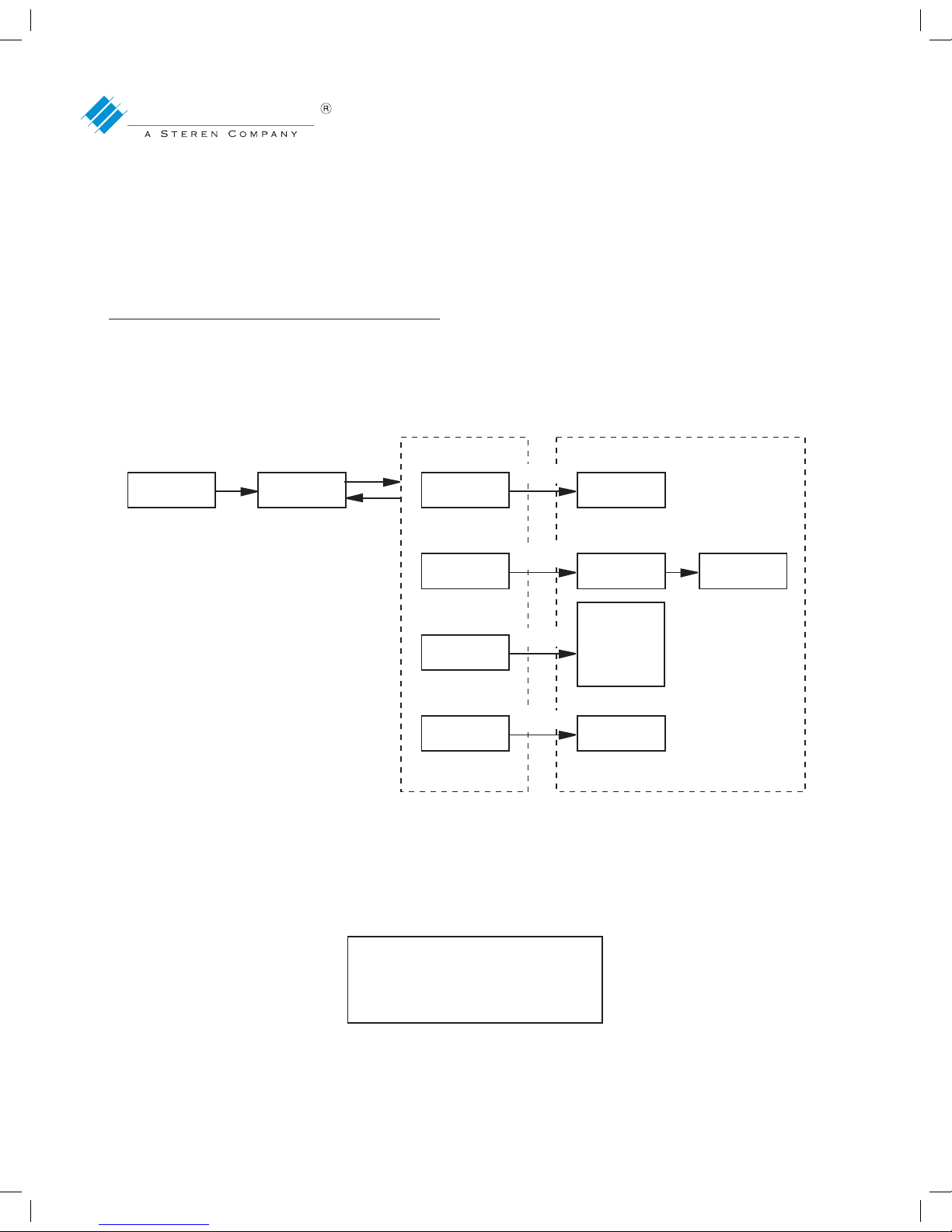
NOTE: After boot-up sequence is completed the MPD-CPS display will show:
figure 4
BOOT UP UNIT
SELECT
CH SEARCH
YES
NO
CHANNEL
TV
SYSTEM
VOLUME
RF
LIST
8VSB
QAM J.83B
CATV STD
CATV HRC
CATV IRC
VOL VALUE
SET
PROG
LIST
Enter
Up/Dn
Up/Dn
Up/Dn
Up/Dn
Enter
Enter
Enter
Enter
MAIN MENU SUB MENU
figure 5
PICO
MPD
= = =
= = =
= = =
= = =
MPD Owners Manual.indd 9 5/8/08 4:50:57 PM
Page 10

10
CONTACT US TOLL FREE 800-421-6511
www.picomacom.com
PICO MACOM
MPD
ATSC/8VS B/QAM Dem odulator
MPD-CPS
Controller/Power Supply
To begin programming the MPD, press the ENTER button once.
The screen will appear as follows:
Note: The default TV mode of the controller is 8VSB. If no operation has been performed for 30 seconds the screen
will revert to the screen shown in figure 5. To proceed from last screen push ENTER key.
To proceed press ENTER once again. The following screen will appear:
REMINDER: Please verify an antenna cable is connected to the input of each MPD prior to scanning. Press the
ENTER button to begin channel search or scanning. To stop scanning, press the LEFT ← key once.
figure 6
U
S
C
V
N
N
H
O
I
R
:
L
T
:
N
U
:
/
M
0
N
A
E
1
/
: 0 5A0
[8 V S B]
figure 7
E
R
L
T
M
C
C
T
A
H
H
V
IAN
S
N
S
E
N
Y
M
A
E
S
N
C
E
U
H
M
T
Y
N
V
EOS
S E A R C H
figure 8
[ 8 V S B ]
figure 9
USNCIATN:N0I1
N G
[8 V S B]
MPD Owners Manual.indd 10 5/8/08 4:51:00 PM
Page 11

11
CONTACT US 858.546.5050
www.picomacom.com
PICO MACOM
MPD
ATSC/8VS B/QAM Dem odulator
MPD-CPS
Controller/Power Supply
After scanning or channel search is completed, the digital channels found are loaded into the CPU of the
MPD-CPS. The display will appear as shown:
To change or program the module to a different digital channel, do the following:
Press ENTER key. This screen will display the following:
Use the DOWN ↓ key to move the → arrow to CHANNEL and press ENTER to select it. The display will be as
shown:
Press ENTER key again to select channel. The display will show:
NOTE: The channels listed in fig. 13 are for example only. They will be different for different areas. The above
shows the active channel is 15-1, shown by the → *. To select a different channel, use the DOWN ↓ key
to move down to the desired channel and press ENTER. The selected channel will show a → * by it. When
finished press the LEFT ← key to return to the MAIN MENU.
figure 10
U
S
C
V
N
N
H
O
I
R
:
L
T
:
5
U
:
1
M
0
2
-
E
1
9
1
: 0B5d0
figure 11
E
R
L
T
M
C
C
T
A
H
H
V
IAN
S
N
S
E
N
Y
M
A
E
S
N
C
E
U
H
M
figure 12
E
R
L
T
M
C
C
T
A
H
H
V
IAN
S
N
S
E
N
Y
M
A
E
S
N
C
E
U
H
M
figure 13
R*F
C
C
C
C
H
H
H
H
L
1
5
1
2
I
5
5
9
0
S
-
-
-
-
T
1
1
1
1
[ 8 V S B ]
MPD Owners Manual.indd 11 5/8/08 4:51:02 PM
Page 12

12
CONTACT US TOLL FREE 800-421-6511
www.picomacom.com
PICO MACOM
MPD
ATSC/8VS B/QAM Dem odulator
MPD-CPS
Controller/Power Supply
Volume Control Programming
From the MAIN MENU press ENTER to display fig. 14:
Use the DOWN ↓ key to select the Volume Menu as shown:
Verify the arrow → is on VOLUME. Press ENTER to select it (fig. 16).
Use UP ↑ or DOWN ↓ keys to adjust the volume to desired level.
Note: For best operation set the volume to 50 and then set the modulator audio deviation to 50kHz p-p.
TV Mode Programming - 8VSB or QAM
Go to MAIN MENU using the LEFT ← key. Press it one or two times depending on where you are in the Sub Menu.
The screen will display:
figure 14
E
R
L
T
M
C
C
T
A
H
H
V
IAN
S
N
S
E
N
Y
M
A
E
S
N
C
E
U
H
M
figure 15
E
N
M
V
A
V
A
O
S
E
I
L
P
R
N
U
E
S
M
C
I
M
E
T
O
NRU
A T I O
figure 16
V O L U>M>E
5 0
figure 17
E
R
L
T
M
C
C
T
A
H
H
V
IAN
S
N
S
E
N
Y
M
A
E
S
N
C
E
U
H
M
figure 18
E
R
L
T
M
C
C
T
A
H
H
V
IAN
S
N
S
E
N
Y
M
A
E
S
N
C
E
U
H
M
figure 19
T*V
8QV
A
S
S
M
YBSJT.E8M
3 B
.
figure 20
T V
C
C
C
A
A
A
S
T
T
T
Y
V
V
V
S
-
-
-
T
S
H
I
E
T
R
R
M
D
C
C
MPD Owners Manual.indd 12 5/8/08 4:51:05 PM
Page 13

13
CONTACT US 858.546.5050
www.picomacom.com
PICO MACOM
MPD
ATSC/8VS B/QAM Dem odulator
MPD-CPS
Controller/Power Supply
Use the down arrow key to move the → arrow to TV SYSTEM (fig.18).
Press ENTER to show the following screen:
NOTE: The →* shows the 8VSB mode is loaded into the CPU and selected. This is because during the
channel search or scan, the input was 8VSB.
To deselect it and select QAM, press DOWN ↓ key once and press ENTER. The display will show the
following:
To select CATV-STD press the ENTER key. To select CATV-HRC press the DOWN ↓ key and press ENTER.
To program the unit for additional parameters, follow the procedure previously outlined in similar fashion.
figure 18
E
R
L
T
M
C
C
T
A
H
H
V
IAN
S
N
S
E
N
Y
M
A
E
S
N
C
E
U
H
M
figure 19
T*V
8QV
A
S
S
M
YBSJT.E8M
3 B
.
figure 20
T V
C
C
C
A
A
A
S
T
T
T
Y
V
V
V
S
-
-
-
T
S
H
I
E
T
R
R
M
D
C
C
MPD Owners Manual.indd 13 5/8/08 4:51:06 PM
Page 14

14
CONTACT US TOLL FREE 800-421-6511
www.picomacom.com
PICO MACOM
MPD
ATSC/8VS B/QAM Dem odulator
MPD-CPS
Controller/Power Supply
Module Replacement
1. Power Supply / Controller:
a. Disconnect the power cord from the power supply.
b. Disconnect the power and data connectors from power supply.
c. Remove power supply by sliding the unit out the front of the chassis.
d. Insert replacement power supply into chassis.
e. Connect the power and data connectors to the power supply.
f. Reinsert the power cord into power supply.
2. Module:
a. Disconnect the 3-pin power and data connectors from module.
b. Disconnect the audio, video, and RF connectors from back of module.
c. Remove module by sliding the unit out the front of the chassis.
d. Insert replacement module into chassis.
e. Reconnect the audio, video, and RF connectors to the rear of module.
Operation and Care
Do’s & Don’ts
1. Always operate in a cool well-ventilated environment.
2. Always provide a stable conditioned power source.
3. Heed all safety warnings and obey all environmental and electrical operating requirements.
4. To clean, use a damp cloth only and clean only with mild soap.
5. Do not use solvents or harsh detergents.
6. Do not use this product for purposes other than intended.
MPD Owners Manual.indd 14 5/8/08 4:51:06 PM
Page 15
15
CONTACT US 858.546.5050
www.picomacom.com
PICO MACOM
MPD
ATSC/8VS B/QAM Dem odulator
MPD-CPS
Controller/Power Supply
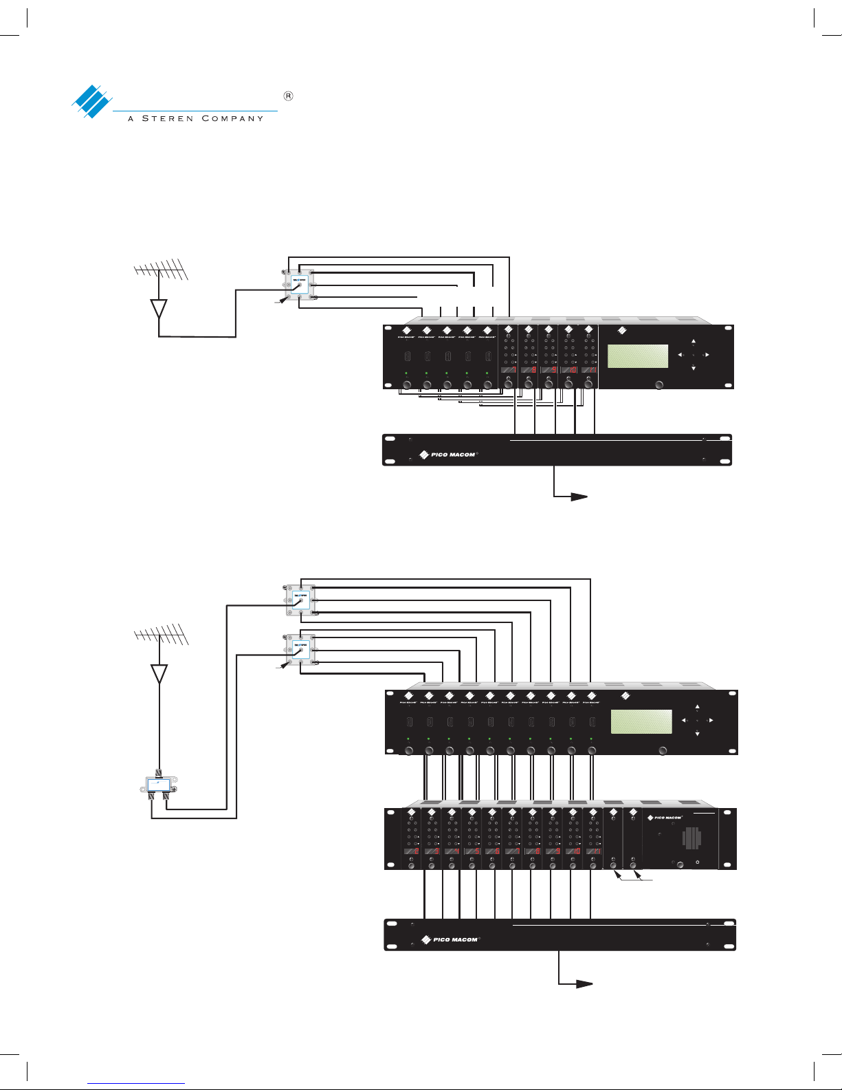
System Configurations
1.
2.
R
OUT
OUT
OUT
OUT
OUT
OUT
OUT OUT
TM
INPUT
TSV-8SB
UHF/VHF ANTENNA
MPA-HD
PHC-12G COMBINER
TSV-8SB
PHC-12G
Passive Headend Combiner
R
5 x 5 Monaural Application
MPD-CPS
Transcoder Controller
LOCK
MPD
Transcoder
UPGRADE
PORT
R
LOCK
MPD
Transcoder
UPGRADE
PORT
R
LOCK
MPD
Transcoder
UPGRADE
PORT
R
LOCK
MPD
Transcoder
UPGRADE
PORT
R
LOCK
MPD
Transcoder
UPGRADE
PORT
R
UNIT O1 [AIR]
SNR : 80%
CHA : 100-12
VOLUME 85
RF OUTPUTS
F-59T’S
(TERMINATE
ALL OPEN PORTS)
AUDIOVIDEO
CH
A/V
RATI
M
P
C
M
A
LOCK
UNLOCK
CATV
ANT
RF
AUDIOVIDEO
CH
A/V
RATI
RF
M
P
C
M
A
LOCK
UNLOCK
CATV
ANT
AUDIOVIDEO
CH
A/V
RATI
RF
M
P
C
M
A
LOCK
UNLOCK
CATV
ANT
AUDIOVIDEO
CH
A/V
RATI
RF
M
P
C
M
A
LOCK
UNLOCK
CATV
ANT
AUDIOVIDEO
CH
A/V
RATI
RF
M
P
C
M
A
LOCK
UNLOCK
CATV
ANT
MPCMA - 5 PCS.
or
MPCM45-5 PCS.
VIDEO/AUDIO
OUTPUTS
MPD - 5 PCS.
TO DISTRIBUTION SYSTEM
5 x 5 Monaural Application
OUT
OUT
OUT
OUT
OUT
OUT
OUT OUT
TM
INPUT
TSV-8SB
OUT
OUT
OUT
OUT
OUT
OUT
OUT OUT
TM
INPUT
TSV-8SB
UHF/VHF ANTENNA
MPA-HD
PHC-12G COMBINER
MPCD-12PCS.
TSB-21G
TSV-8SB
PHC-12G
Passive Headend Combiner
R
MPCMA - 10 PCS.
AUDIO/
VIDEO
OUTPUTS
Monaural Application
INPUT
5-1000MHz
-130dB EMI
OUT
-3.5dB
OUT
-3.5dB
TSB-21G
TRU SPEC
TM
R
MPD-CPS
Transcoder Controller
LOCK
MPD
Transcoder
UPGRADE
PORT
R
LOCK
MPD
Transcoder
UPGRADE
PORT
R
LOCK
MPD
Transcoder
UPGRADE
PORT
R
LOCK
MPD
Transcoder
UPGRADE
PORT
R
LOCK
MPD
Transcoder
UPGRADE
PORT
R
LOCK
MPD
Transcoder
UPGRADE
PORT
R
LOCK
MPD
Transcoder
UPGRADE
PORT
R
LOCK
MPD
Transcoder
UPGRADE
PORT
R
LOCK
MPD
Transcoder
UPGRADE
PORT
R
LOCK
MPD
Transcoder
UPGRADE
PORT
R
MPC-PSF12/16 POWER SUPPLY
AUDIOVIDEO
CH
A/V
RATIO
RF
M
P
C
M
A
LOCK
UNLOCK
CATV
ANT
R
AUDIOVIDEO
CH
A/V
RATIO
RF
M
P
C
M
A
LOCK
UNLOCK
CATV
ANT
AUDIOVIDEO
CH
A/V
RATIO
RF
M
P
C
M
A
LOCK
UNLOCK
CATV
ANT
AUDIOVIDEO
CH
A/V
RATIO
RF
M
P
C
M
A
LOCK
UNLOCK
CATV
ANT
AUDIOVIDEO
CH
A/V
RATIO
RF
M
P
C
M
A
LOCK
UNLOCK
CATV
ANT
AUDIOVIDEO
CH
A/V
RATIO
RF
M
P
C
M
A
LOCK
UNLOCK
CATV
ANT
AUDIOVIDEO
CH
A/V
RATIO
RF
M
P
C
M
A
LOCK
UNLOCK
CATV
ANT
AUDIOVIDEO
CH
A/V
RATIO
RF
M
P
C
M
A
LOCK
UNLOCK
CATV
ANT
AUDIOVIDEO
CH
A/V
RATIO
RF
M
P
C
M
A
LOCK
UNLOCK
CATV
ANT
AUDIOVIDEO
CH
A/V
RATIO
RF
M
P
C
M
A
LOCK
UNLOCK
CATV
ANT
AUDIOVIDEO
CH
A/V
RATIO
RF
M
P
C
M
A
LOCK
UNLOCK
CATV
ANT
UNIT O1 [AIR]
SNR : 80%
CHA : 100-12
VOLUME 85
MPD - 10 PCS.
RF OUTPUTS
F-59T
’S
(TERMINATE
ALL OPEN PORTS)
MOR-BP
TO DISTRIBUTION SYSTEM
MPD Owners Manual.indd 15 5/8/08 4:51:13 PM
Page 16
16
CONTACT US TOLL FREE 800-421-6511
www.picomacom.com
PICO MACOM
MPD
ATSC/8VS B/QAM Dem odulator
MPD-CPS
Controller/Power Supply
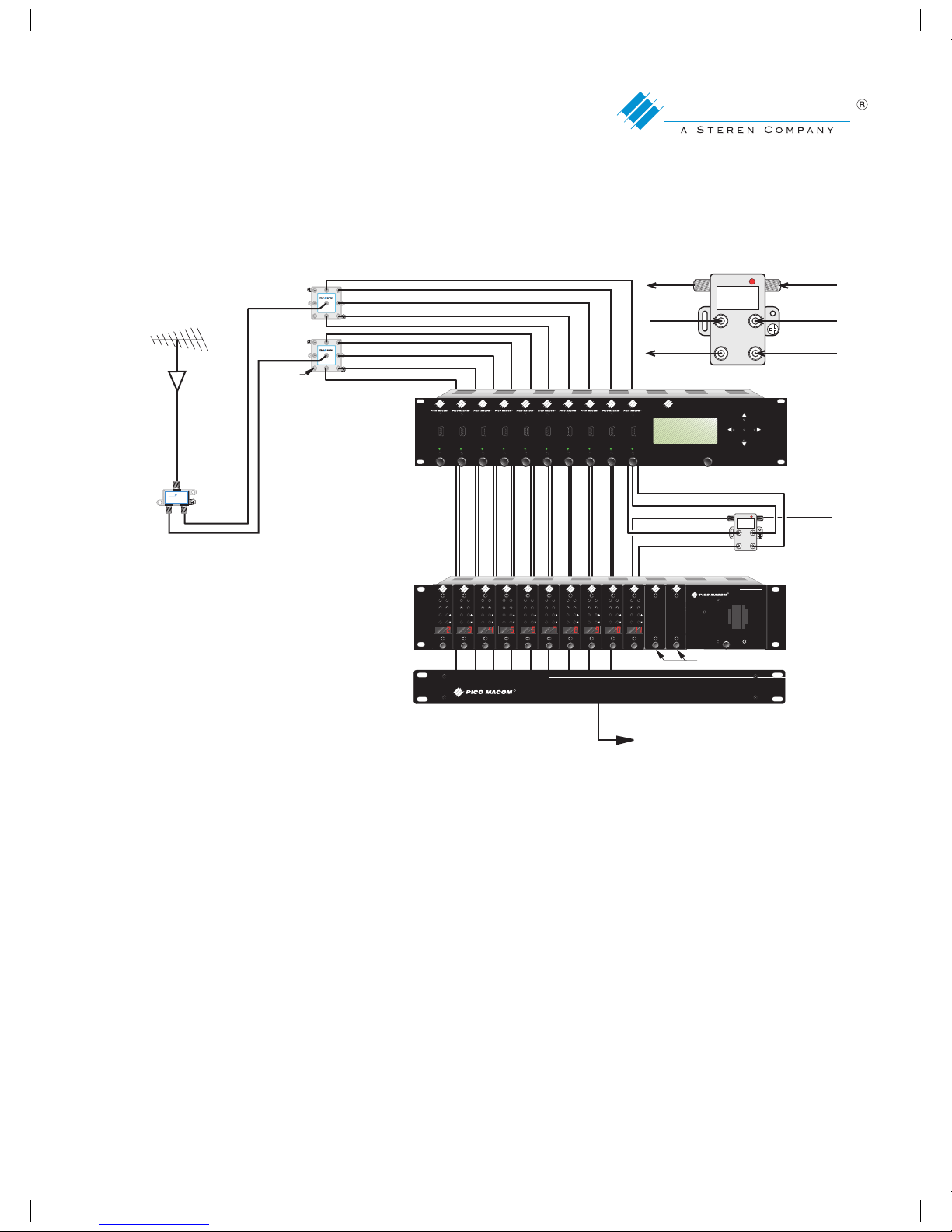
System Configurations
3.
POWER
5 Vdc
AUDIO
OUTPUT
AUDIO L
AUDIO R
VIDEO IN
VIDEO OUT
OUT
OUT
OUT
OUT
OUT
OUT
OUT OUT
TM
INPUT
TSV-8SB
OUT
OUT
OUT
OUT
OUT
OUT
OUT OUT
TM
INPUT
TSV-8SB
UHF/VHF ANTENNA
MPA-HD
PHC-12G COMBINER
MPCD-12PCS.
TSB-21G
TSV-8SB
PHC-12G
Passive Headend Combiner
R
MPCMA - 10 PCS.
AUDIO/
VIDEO
OUTPUTS
Stereo Application
INPUT
5-1000MHz
-130dB EMI
OUT
-3.5dB
OUT
-3.5dB
TSB-21G
TRU SPEC
TM
R
MPD-CPS
Transcoder Controller
LOCK
MPD
Transcoder
UPGRADE
PORT
R
LOCK
MPD
Transcoder
UPGRADE
PORT
R
LOCK
MPD
Transcoder
UPGRADE
PORT
R
LOCK
MPD
Transcoder
UPGRADE
PORT
R
LOCK
MPD
Transcoder
UPGRADE
PORT
R
LOCK
MPD
Transcoder
UPGRADE
PORT
R
LOCK
MPD
Transcoder
UPGRADE
PORT
R
LOCK
MPD
Transcoder
UPGRADE
PORT
R
LOCK
MPD
Transcoder
UPGRADE
PORT
R
LOCK
MPD
Transcoder
UPGRADE
PORT
R
MPC-PSF12/16 POWER SUPPLY
AUDIOVIDEO
CH
A/V
RATIO
RF
M
P
C
M
A
LOCK
UNLOCK
CATV
ANT
R
AUDIOVIDEO
CH
A/V
RATIO
RF
M
P
C
M
A
LOCK
UNLOCK
CATV
ANT
AUDIOVIDEO
CH
A/V
RATIO
RF
M
P
C
M
A
LOCK
UNLOCK
CATV
ANT
AUDIOVIDEO
CH
A/V
RATIO
RF
M
P
C
M
A
LOCK
UNLOCK
CATV
ANT
AUDIOVIDEO
CH
A/V
RATIO
RF
M
P
C
M
A
LOCK
UNLOCK
CATV
ANT
AUDIOVIDEO
CH
A/V
RATIO
RF
M
P
C
M
A
LOCK
UNLOCK
CATV
ANT
AUDIOVIDEO
CH
A/V
RATIO
RF
M
P
C
M
A
LOCK
UNLOCK
CATV
ANT
AUDIOVIDEO
CH
A/V
RATIO
RF
M
P
C
M
A
LOCK
UNLOCK
CATV
ANT
AUDIOVIDEO
CH
A/V
RATIO
RF
M
P
C
M
A
LOCK
UNLOCK
CATV
ANT
AUDIOVIDEO
CH
A/V
RATIO
RF
M
P
C
M
A
LOCK
UNLOCK
CATV
ANT
AUDIOVIDEO
CH
A/V
RATIO
RF
M
P
C
M
A
LOCK
UNLOCK
CATV
ANT
UNIT O1 [AIR]
SNR : 80%
CHA : 100-12
VOLUME 85
MPD - 10 PCS.
RF OUTPUTS
F-59T’S
(TERMINATE
ALL OPEN PORTS)
POWER
L AUDIO
FROM MPD
R AUDIO
FROM MPD
TO MOD
AUDIO IN
TO MOD
VIDEO IN
PM-SE
POWER
5 Vdc
AUDIO
OUTPUT
AUDIO L
AUDIO R
VIDEO IN
VIDEO OUT
MPD VIDEO
VIDEO TO MOD
AUDIO TO MOD
MPD L-AUDIO
MPD R-AUDIO
POWER
MOR-BP
TO DISTRIBUTION SYSTEM
MPD Owners Manual.indd 16 5/8/08 4:51:17 PM
Page 17

17
CONTACT US 858.546.5050
www.picomacom.com
PICO MACOM
MPD
ATSC/8VS B/QAM Dem odulator
MPD-CPS
Controller/Power Supply
Limited Warranty
Pico Macom warrants to the original purchaser that all of its new products are of sound design, quality materials and
workmanship at the time of manufacture and will be free from related defects for one year from the original purchase
date. Pico Macom will repair or, at its discretion, replace without cost to the original purchaser, the product which,
upon inspection by Pico Macom, appears to be defective or not conforming to factory specifications. Pico Macom will
cover the cost of parts, labor, and return freight from factory.
Five-Year Limited Warranty
The MPD (and excluding the MPD-CPS) is covered by an extended 4-year period beyond the expiration of
the original 1-year warranty, for a full 5-year period. Qualified equipment requiring factory repair during the
extended 4-year period is covered under our re-certification program. Re-certification fees under this program shall not to exceed 20% of the product’s List Price and whenever possible, Pico Macom will attempt
to upgrade performance to the latest improved specification.
Three-Year Limited Warranty
The MPD-CPS is further covered by an extended 2-year period beyond the expiration of the original 1-year warranty, for a full 3-year period. Qualified equipment requiring factory repair during
the extended 3-year period is covered under our re-certification program. Re-certification fees
under this program shall not exceed 20% of the product’s List Price and, whenever Possible, Pico
Macom will attempt to upgrade performance to the latest improved specification.
Warranty Limitations
This warranty excludes coverage of damage or inoperability resulting from (1) use or installation other than
in strict accordance with Pico Macom’s written instructions, (2) disassembly or repair by someone other than
Pico Macom or a Pico Macom authorized repair center, (3) misuse, misapplication or abuse, (4) alteration,
(5) lack of reasonable care or (6) wind, ice, snow, rain, lightning, power surges, excessive heat, or any other
weather conditions or acts of God. Pico Macom’s warranty with respect to third-party proprietary sub-assembly modules and/or private-label products are limited to the duration and terms of third-party vendors’
warranty. Pico Macom shall in no event and under no circumstances be liable or responsible for any consequential, indirect, incidental, punitive, direct or special damages based upon breach of warranty, breach of
contract, negligence, strict tort liability or otherwise or any other legal theory, arising directly or indirectly
from the sale, use, installation or failure of any product acquired by buyer from Pico Macom. This limited
warranty extends to the original purchaser. Pico Macom reserves the right to modify or discontinue this warranty at Pico Macom’s sole discretion without notification. No other warrantees are expressed or implied.
Damage or Shortage Claims
Our shipping staff carefully packs and ships your orders in compliance with common carriers’ requirements.
Please make note of any obvious damage or shortage on the freight bill or carrier’s receipt next to your signature. The carrier’s agent must too sign acknowledging the loss. Failure to do so may result in the carrier’s
refusal to honor the claim. Please open your order immediately upon receipt to check for concealed damage and compare the packing list to the items shipped. If damaged, keep the original shipping cartons for
possible inspection by the carrier. You must report claims for loss or damage within 3 days of delivery, while
claims for erroneous charges or price corrections must be presented within 30 days of invoice date.
MPD Owners Manual.indd 17 5/8/08 4:51:18 PM
Page 18

18
CONTACT US TOLL FREE 800-421-6511
www.picomacom.com
PICO MACOM
MPD
ATSC/8VS B/QAM Dem odulator
MPD-CPS
Controller/Power Supply
Returning Shipped Items
To return any shipped items, including those shipped for warranty repairs or credit, call our Customer
Service desk to request a Return Merchandise Authorization (RMA) number. Please reference the original
invoice number and purchase date, and product serial number (if any). Be certain to mark the RMA number
on the package boldly and legibly. Unless we specify a different carrier, please ship your returned items to
us via UPS freight prepaid and fully insured. If returned for credit, we will promptly process your request
upon receipt of your return order.
Our Return Policy: Your Satisfaction Guaranteed
Our goal is your complete satisfaction. If for any reason, our products were not quite what you anticipated,
simply call your customer service rep and we will be happy to assist you in replacing or returning the order.
You may return current, non-discontinued items for full credit for up to 30 days from invoice date. Our requirements are simple: Excepting defective items, the products must be returned in their original packaging
and in re-salable condition. Restocking fees may otherwise apply beyond this period or if products are not
returned in their original condition. Please contact your customer service rep for more information.
MPD Owners Manual.indd 18 5/8/08 4:51:18 PM
 Loading...