

Page 1

MEsstechnik fängt mit ME an.
Produkt-Datenblatt
Technische Daten, Spezifikationen
www.meilhaus.com
Erwähnte Firmen- und Produktnamen sind zum Teil
eingetragene Warenzeichen der jeweiligen Hersteller.
Preise in Euro zzgl. gesetzl. MwSt. Irrtum und Änderung
vorbehalten.
© Meilhaus Electronic bzw. Hersteller.
www.meilhaus.de/infos/impressum.htm
Kontakt
Technischer und kaufmännischer Vertrieb, Preisauskünfte, Angebote, Test-Geräte, Beratung vor Ort:
Tel: (0 81 41) 52 71-0
FAX: (0 81 41) 52 71-129
Aus dem Ausland:
Tel: ++49 - 81 41 - 52 71-0
FAX: ++49 - 81 41 - 52 71-129
E-Mail: [email protected]
Internet:
www.meilhaus.com
Web-Shop:
www.MEsstechnik24.de | www.MEasurement24.com
Web Kontakt-Formular:
www.meilhaus.de/infos/Kontakt.htm
Per Post:
Meilhaus Electronic GmbH
Am Sonnenlicht 2
D-82239 Alling bei München
Page 2
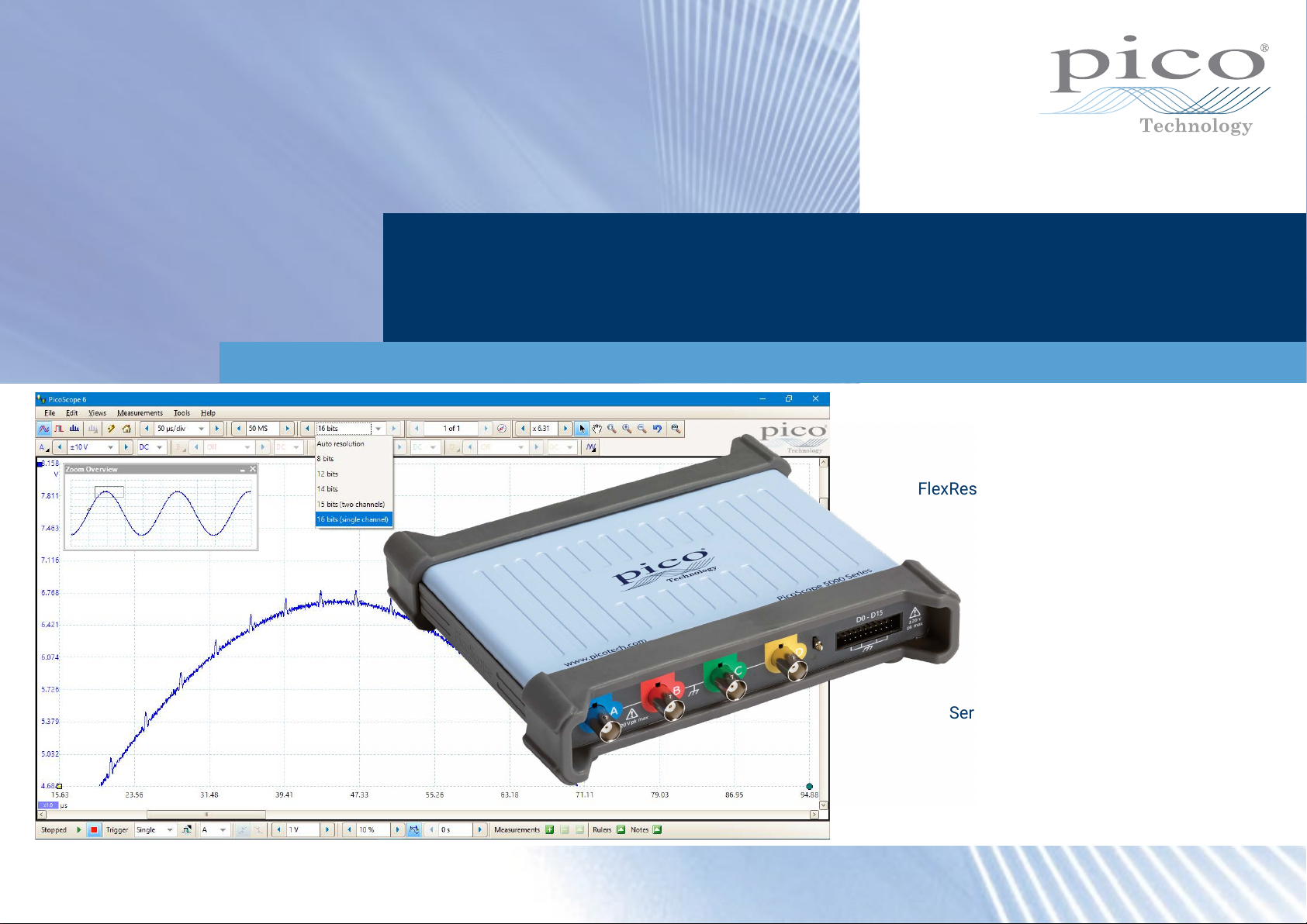
PicoScope® 5000D Series
FlexRes® oscilloscopes and MSOs
The complete all-rounders
FlexRes exible 8 to 16-bit hardware resolution
Up to 200 MHz analog bandwidth
1 GS/s sampling at 8-bit resolution
500 MS/s sampling at 12-bit resolution
62.5 MS/s sampling at 16-bit resolution
Up to 512 MS capture memory
16 digital channels (on MSO models)
130 000 waveforms per second
Built-in arbitrary waveform generator
Serial decoding as standard (18 protocols)
Up to 200 MHz spectrum analyzer
Silent, fanless design
Page 3
Introduction
Today’s electronic designs employ a wide
range of signal types: analog, digital,
serial (both high- and low-speed), parallel,
audio, video, power distribution and so on.
All need to be debugged, measured and
validated to ensure that the device under
test is functioning correctly and within
specication.
To handle this variety of signal types,
PicoScope 5000D Series FlexRes
oscilloscopes provide 8 to 16 bits of
vertical resolution, with up to 200 MHz
bandwidth and 1 GS/s sampling speed.
You select the most appropriate hardware
resolution for the requirements of each
measurement.
PicoScopes include advanced features
such as mask limit testing, serial
decoding, advanced triggering, automatic
measurements, math channels (including
the ability to plot frequency and duty cycle
against time), XY mode and segmented
What is FlexRes?
Pico FlexRes exible resolution
oscilloscopes allow you to recongure
the scope hardware to increase either the
sampling rate or the resolution.
memory. The PicoScope 5000D Series
also benets from Pico’s award-winning
DeepMeasure™ feature and FlexRes
exible resolution.
Other key features of the PicoScope
5000D Series include:
• Deep capture memory – from 128
million to 512 million samples
• 2 or 4 analog channels
• Mixed-signal models add 16 digital
channels
• Serial decoding – analyze 18 protocols
• USB 3.0 connection for continuous
high-speed data streaming
• Small, light and portable
Supported by the free and regularly
updated PicoScope 6 software, these
devices offer an ideal, cost-effective
package for many applications, including
design, research, test, education, service
and repair.
Whether you’re capturing and decoding
fast digital signals or looking for distortion
in sensitive analog signals, FlexRes
oscilloscopes are the answer.
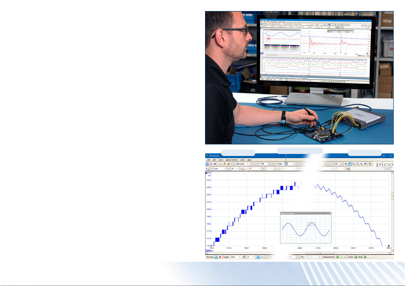
Flexible resolution
16-bit mode8-bit mode
This means you can recongure the
hardware to be either a fast (1 GS/s) 8-bit
oscilloscope for looking at digital signals
or a high-resolution 16-bit oscilloscope for
audio work and other analog applications.
PicoScope® 5000D Series oscilloscopes
Page 4
Advanced display
PicoScope 6 software dedicates the majority of the display area to the waveform,
ensuring that the maximum amount of data is visible at all times. The size of the display
is only limited by the size of your computer’s monitor, so even with a laptop, the viewing
area is much bigger, with much higher resolution, than that of a benchtop scope.
With such a large display area available, you can create a customizable split-screen
display and view multiple channels or different views of the same signal at the same
time – the software can even show multiple oscilloscope and spectrum analyzer views
at once.
Each view has separate zoom, pan and lter settings for ultimate exibility.
You can control the PicoScope 6 software using a mouse, touchscreen or customizable
keyboard shortcuts.
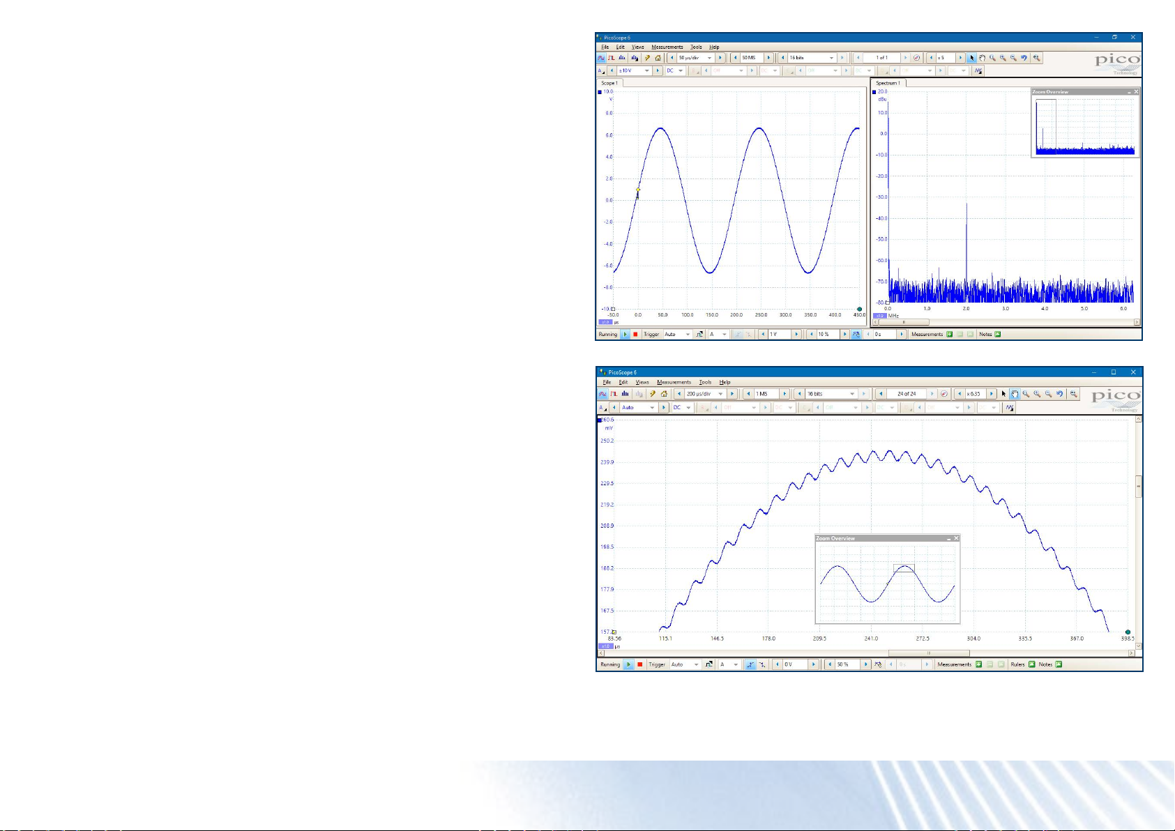
Low-level signals
With its 16-bit resolution, the PicoScope 5000D Series can magnify low-level signals
at high zoom factors. This allows you to view and measure features such as noise and
ripple superimposed on larger DC or low-frequency voltages.
Additionally, you can use the Lowpass Filtering controls on each channel independently,
to hide noise and reveal the underlying signal.
PicoScope® 5000D Series oscilloscopes
Page 5
High bandwidth, high sampling rate
Many USB-powered oscilloscopes have
real-time sampling rates of only 100 or
200MS/s, but the PicoScope 5000D
Series offers up to 1 GS/s, and a maximum
bandwidth of 200MHz.
Deep capture memory
PicoScope 5000D Series oscilloscopes
have waveform capture memories
ranging from 128 megasamples to 512
megasamples – many times larger than
competing scopes. Deep memory enables
the capture of long-duration waveforms
at maximum sampling speed. In fact,
the PicoScope 5000D Series can capture
waveforms over 500ms long with 1ns
resolution. In contrast, the same 500ms
waveform captured by an oscilloscope
with a 10megasample memory would
have just 50ns resolution.
Deep memory can be useful in other
ways too: PicoScope 6 lets you divide
the capture memory into a number of
segments, up to a maximum of 10 000.
You can set up a trigger condition to store
a separate capture in each segment,
with as little as 1 µs dead time between
captures. Once you have acquired the
data, you can step through the memory
one segment at a time until you nd the
event you are looking for.
Powerful tools are included to allow you
to manage and examine all of this data.
As well as functions such as mask limit
testing and color persistence mode, the
PicoScope 6 software enables you to
zoom into your waveform by a factor
of several million. The Zoom Overview
window allows you to easily control the
size and location of the zoom area. Other
tools, such as the waveform buffer, serial
Equivalent time sampling (ETS) mode
can be used to further boost the effective
sampling rate to 10 GS/s for a more
detailed view of repetitive signals.
decoding and hardware acceleration
work with the deep memory, making the
PicoScope 5000D some of the most
powerful oscilloscopes on the market.
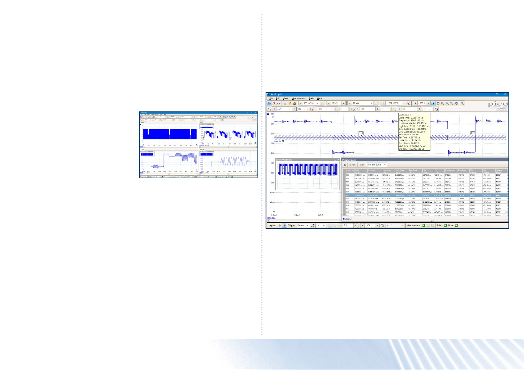
DeepMeasure
The PicoScope 6 DeepMeasure tool uses
deep memory to analyze every cycle
contained in each triggered waveform
acquisition. It displays the results in a
table, with the parameter elds shown in
columns and waveform cycles shown in
rows: you can easily sort the results by
any parameter and correlate them with the
waveform display.
Waveform buffer and navigator
Ever spotted a glitch on a waveform, but
by the time you’ve stopped the scope it’s
gone? With PicoScope you no longer need
to worry about missing glitches or other
transient events, as it can store the last
10000 waveforms in its circular waveform
buffer.
The current version of the tool includes
sixteen parameters per cycle, and can
display up to a million cycles.
Parameters include cycle time, frequency,
pulse width, duty cycle, rise and fall time,
overshoot, undershoot, max voltage and
min voltage. Start and end times relative to
the trigger are given for each cycle.
The buffer navigator provides an ecient
way of navigating and searching through
waveforms, effectively letting you turn
back time. When carrying out a mask limit
test, you can also set the navigator to
show only mask fails, enabling you to nd
any glitches quickly.
PicoScope® 5000D Series oscilloscopes
Page 6
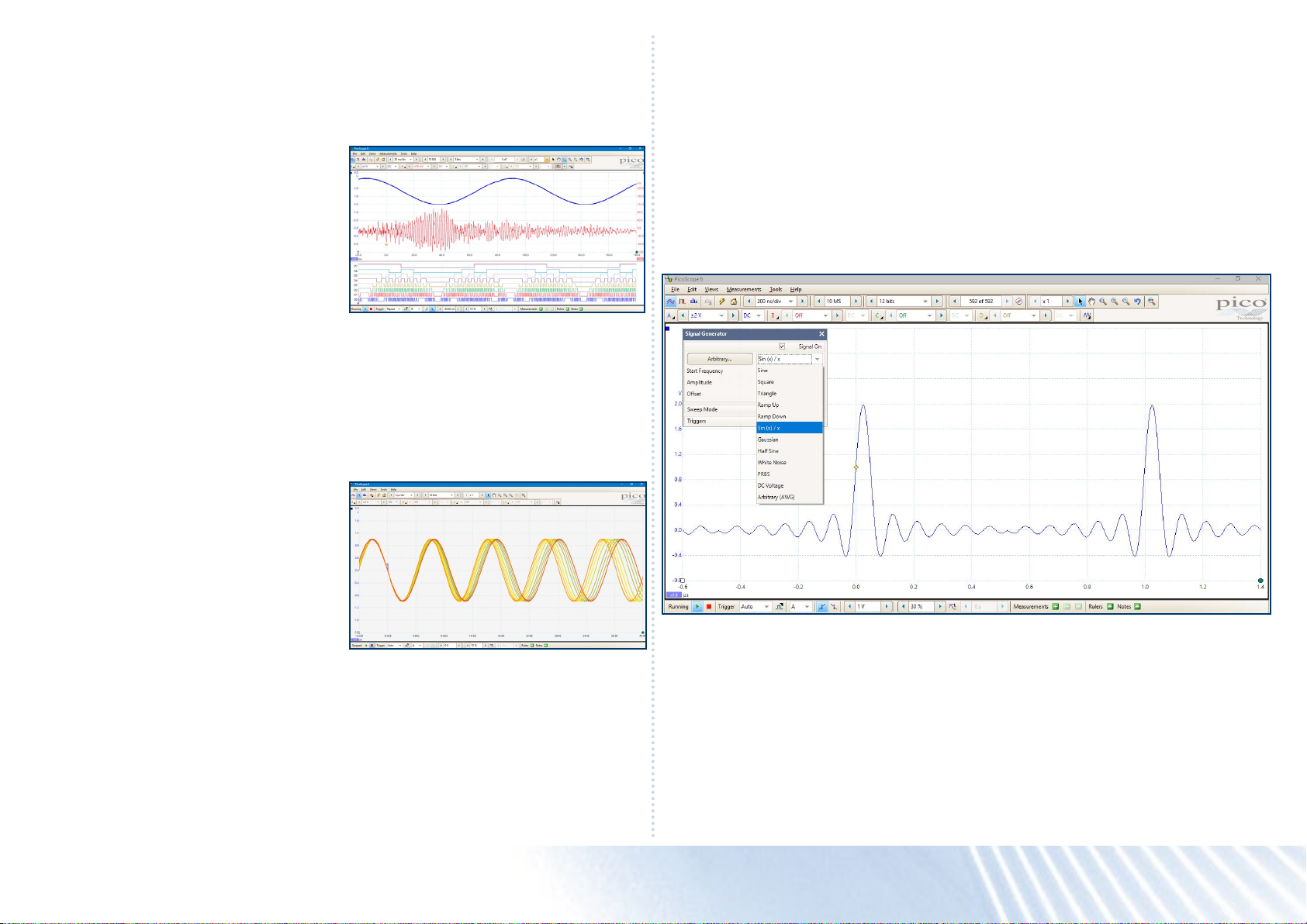
Mixed-signal models
The PicoScope 5000D MSO models add
16 digital channels to the 2 or 4 analog
channels, enabling you to accurately
time-correlate analog and digital channels.
Digital channels may be grouped and
displayed as a bus, with each bus value
displayed in hex, binary or decimal or
as a level (for DAC testing). You can set
advanced triggers across both the analog
and digital channels.
The digital inputs also bring extra power
to the serial decoding options. You can
decode serial data on all analog and digital
Persistence mode
PicoScope 6 persistence mode options
allow you to see old and new data
superimposed, with newer waveforms
drawn in a brighter color or deeper shade.
This makes it easy to spot glitches and
dropouts and estimate their relative
frequency – useful for displaying and
interpreting complex analog signals
such as video waveforms and analog
modulation signals.
channels simultaneously, giving you up
to 20 channels of data – for example
decoding multiple SPI, I²C, CAN bus, LIN
bus and FlexRay signals all at the same
time.
Color-coding or intensity-grading shows
which areas are stable and which are
intermittent. Choose between analog
intensity, digital color and fast display
modes or create your own custom setup.
Arbitrary waveform and function generator
All PicoScope 5000D units have a
built-in 14-bit 200MS/s arbitrary waveform
generator (AWG). You can create and
adapt arbitrary waveforms using the
built-in editor, import them from existing
oscilloscope traces, or load a waveform
from a spreadsheet.
The AWG can also act as a function
generator with a range of standard output
signals, including sine, square, triangle, DC
level, white noise and PRBS.
As well as the basic controls to set level,
offset and frequency, more advanced
controls allow you to sweep over a
range of frequencies. Combined with the
spectrum peak hold option, this makes a
powerful tool for testing amplier and lter
responses.
Trigger tools allow you to output one or
more cycles of a waveform when various
conditions are met, such as the scope
triggering or a mask limit test failing.
The PicoScope 5000D Series’ HAL3
hardware acceleration means that, in Fast
Persistence mode, waveform update rates
of up to 130 000 waveforms per second
are achievable.
PicoScope® 5000D Series oscilloscopes
Page 7
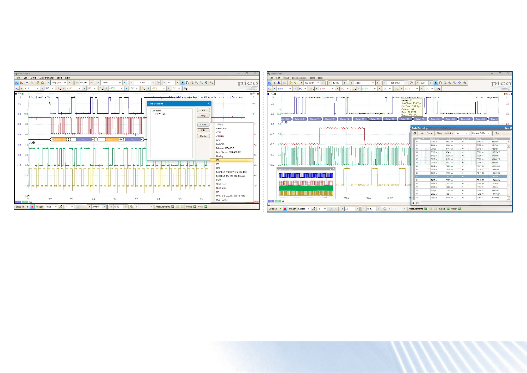
Serial decoding and analysis
With its deep memory, the PicoScope 5000D Series is ideally suited to serial decoding and analysis, which are included as standard.
2
The PicoScope 6 software has support for 18 protocols including I
Decoding helps you see what is happening in your design to identify programming and timing errors and check for other signal integrity issues. Timing analysis tools help to show
the performance of each design element, identifying parts of the design that need to be improved to optimize overall system performance.
C, SPI, CAN, RS-232 and Ethernet.
Graph format shows the decoded data (in
hex, binary, decimal or ASCII) in a timing
diagram format, beneath the waveform
on a common time axis, with error frames
marked in red.
You can zoom in on these frames to
investigate noise or distortion, and each
packet eld is assigned a different color,
so the data is easy to read.
Table format shows a list of the decoded
frames, including the data and all ags
and identiers. You can set up ltering
conditions to display only the frames you
are interested in or search for frames with
specied properties.
The statistics option reveals more detail
about the physical layer such as frame
times and voltage levels. PicoScope 6 can
also import a spreadsheet to decode the
data into user-dened text strings.
PicoScope® 5000D Series oscilloscopes
Page 8
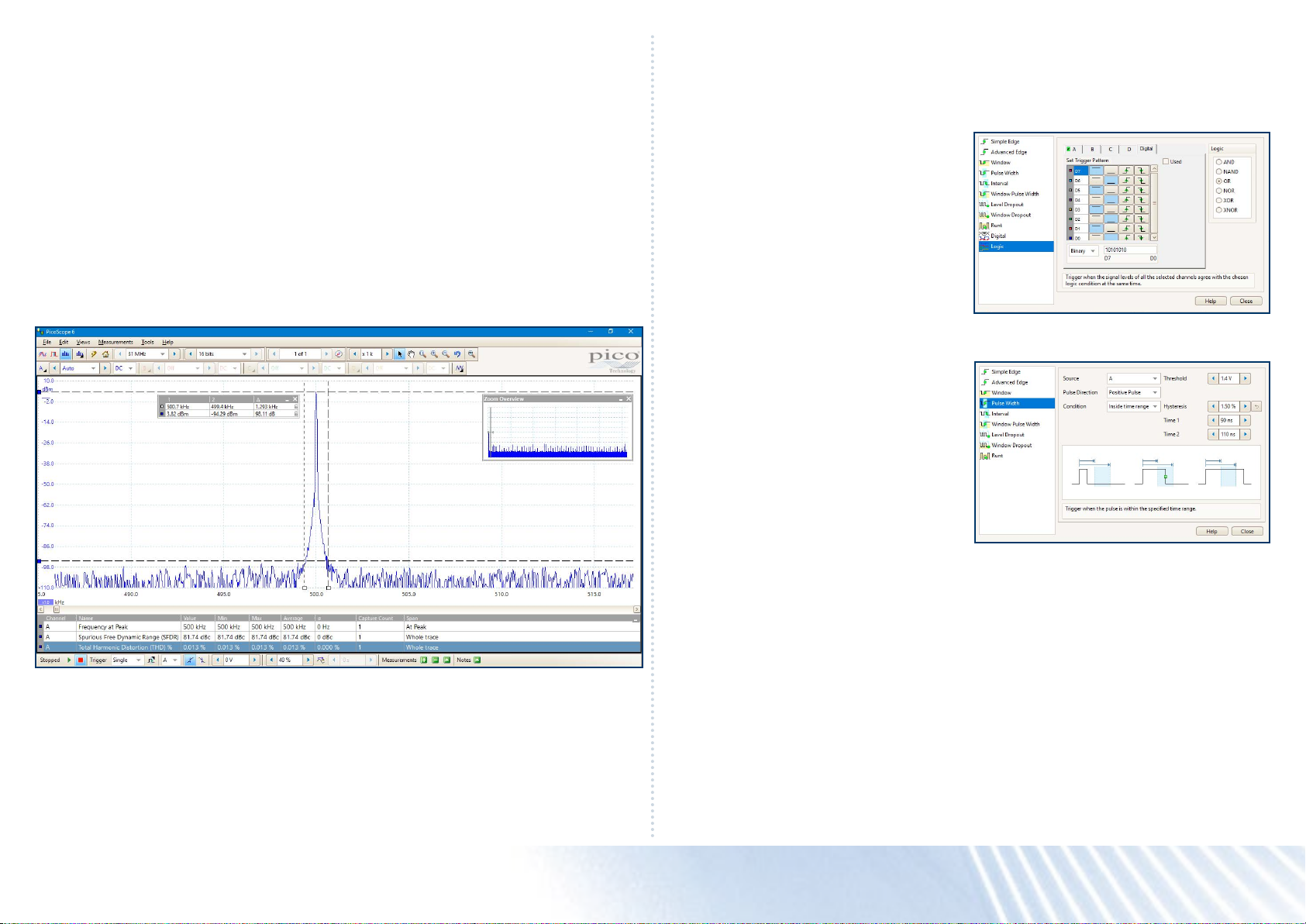
The spectrum view plots amplitude
against frequency and is ideal for nding
noise, crosstalk or distortion in signals.
PicoScope 6 uses a fast Fourier transform
(FFT) spectrum analyzer, which (unlike a
traditional swept spectrum analyzer) can
display the spectrum of a single, nonrepeating waveform.
With a click of a button, you can display a
spectrum plot of the active channels, with
a maximum frequency of up to 200 MHz.
A comprehensive range of settings gives
you control over the number of spectrum
bins, window functions, scaling (including
log/log) and display mode (instantaneous,
average or peak-hold).
Display multiple spectrum views with
different channel selections and zoom
factors, and place these alongside timedomain views of the same data. Choose
from a number of automatic frequencydomain measurements to add to the
display, including THD, THD+N, SNR,
SINAD and IMD. You can apply mask limit
testing to a spectrum and can even use
the AWG and spectrum mode together to
perform swept scalar network analysis.
Advanced triggers Spectrum analyzer
The PicoScope 5000D Series offers
an industry-leading set of advanced
triggers including pulse width, runt pulse,
windowed and dropout.
The digital trigger available on MSO
models allows you to trigger the scope
when any or all of the 16 digital inputs
match a user-dened pattern. You can
specify a condition for each channel
individually, or set up a pattern for all
channels at once using a hexadecimal or
binary value.
You can also use the logic trigger to
Digital triggering architecture
In 1991, Pico Technology pioneered the
use of digital triggering and precision
hysteresis using the actual digitized data.
Traditionally, digital oscilloscopes have
used an analog trigger architecture based
on comparators, which can cause time
and amplitude errors that cannot always
be calibrated out. Additionally, the use of
comparators can often limit the trigger
sensitivity at high bandwidths and can
create a long trigger rearm delay.
combine the digital trigger with an edge
or window trigger on any of the analog
inputs, for example to trigger on data
values in a clocked parallel bus.
Pico’s technique of fully digital triggering
reduces trigger errors and allows our
oscilloscopes to trigger on the smallest
signals, even at the full bandwidth, so you
can set trigger levels and hysteresis with
high precision and resolution.
The digital trigger architecture also
reduces the rearm delay. Combined with
the segmented memory, this enables you
to use rapid triggering to capture 10000
waveforms in 10ms in 8-bit mode.
PicoScope® 5000D Series oscilloscopes
Page 9
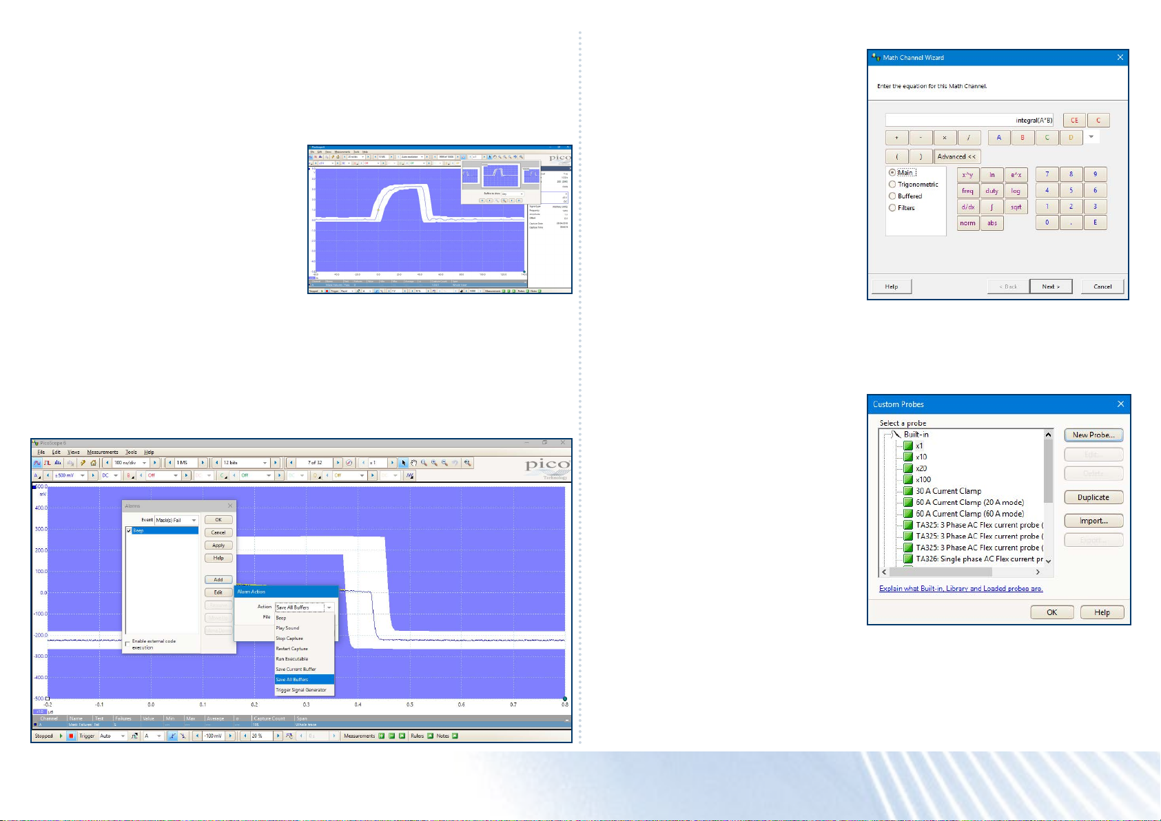
Mask limit testing
Mask limit testing allows you to compare
live signals against known good signals,
and is designed for production and
debugging environments. Simply capture
a known good signal, generate a mask
around it and then use the alarms
to automatically save any waveform
(complete with a time stamp) that violates
the mask. PicoScope 6 will capture any
intermittent glitches and show a failure
count in the Measurements window (which
you can still use for other measurements).
You can also set the waveform buffer
navigator to show only mask fails,
enabling you to nd any glitches quickly.
Mask les are easy to edit (numerically
or graphically), import and export, and
you can simultaneously run mask limit
tests on multiple channels and in multiple
viewports.
Alarms
You can program PicoScope 6 to execute actions when certain events occur.
The events that can trigger an alarm include mask limit fails, trigger events and buffers
full.
PicoScope 6 actions include saving a le, playing a sound, executing a program and
triggering the arbitrary waveform generator.
Math channels and lters
With PicoScope 6 you can perform a
variety of mathematical calculations
on your input signals and reference
waveforms. Select simple functions
such as addition and inversion, or open
the equation editor to create complex
functions involving lters (lowpass,
highpass, bandpass and bandstop lters),
trigonometry, exponentials, logarithms,
statistics, integrals and derivatives.
Display up to eight real or calculated
channels in each scope view. If you run
out of space, just open another scope view
and add more. You can also use math
channels to reveal new details in complex
signals, for example graphing the changing
duty cycle or frequency of your signal over
time.
Custom probes
The custom probes feature allows you to
correct for gain, attenuation, offsets and
nonlinearities in probes, transducers and
other sensors, and to measure quantities
other than voltages (such as current,
power or temperature). Denitions for
standard Pico-supplied probes are built
in, but you can also create your own using
linear scaling or even an interpolated data
table, and save them for later use.
PicoScope® 5000D Series oscilloscopes
Page 10
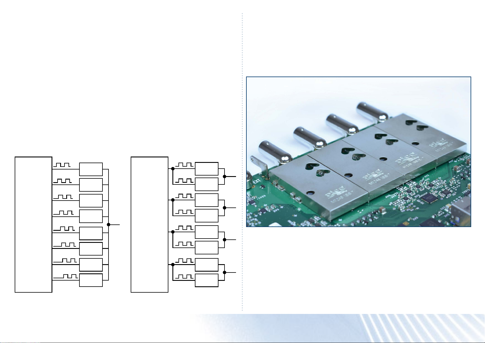
FlexRes – how we do it High signal integrity
Most digital oscilloscopes gain their high
sampling rates by interleaving multiple
8-bit ADCs. Despite careful design,
the interleaving process introduces
errors that always make the dynamic
performance worse than the performance
of the individual ADC cores. The FlexRes
architecture employs multiple
high-resolution ADCs at the input channels
in different time-interleaved and parallel
combinations to optimize either the
sampling rate to 1 GS/s at 8 bits, the
resolution to 16 bits at 62.5 MS/s, or
other combinations in between. Coupled
with high signal-to-noise ratio ampliers
and a low-noise system architecture,
FlexRes technology enables PicoScope
5000D Series oscilloscopes to capture
and display signals up to 200 MHz with
a high sampling rate, or lower-speed
signals with 256 times more resolution
than typical 8-bit oscilloscopes. Resolution
enhancement—a digital signal processing
technique built into PicoScope6 can
further increase the effective vertical
resolution of the scope to 20bits.
The PicoScope 6 software lets you choose
between setting the resolution manually
and leaving the scope in “auto resolution”
mode, where the optimal resolution is
used for the chosen settings.
Here at Pico, we’re proud of the dynamic
performance of our products. Careful
front-end design and shielding reduces
noise, crosstalk and harmonic distortion.
Over 25 years of high-resolution
oscilloscope design experience leads to
improved pulse response and bandwidth
atness.
Sensitivity at 1:1 zoom is an impressive
2mV/div at the full resolution of the
oscilloscope. If you need even more
sensitivity, simply switch to high-resolution
mode and zoom in. Combining 14-bit
mode and zoom can provide 200µV/div
sensitivity while still providing more than
8bits usable resolution.
TIMING
125 MS/s
125 MS/s
125 MS/s
125 MS/s
125 MS/s
125 MS/s
125 MS/s
125 MS/s
TIME-INTERLEAVED
ADC
ADC
ADC
ADC
ADC
ADC
ADC
ADC
TIMING
PARALLEL
ADC
125 MS/s
ADC
125 MS/s
ADC
125 MS/s
ADC
125 MS/s
ADC
125 MS/s
ADC
125 MS/s
ADC
125 MS/s
ADC
125 MS/s
SuperSpeed USB 3.0 connection
PicoScope 5000D Series oscilloscopes feature a USB3.0 connection, providing lightningfast saving of waveforms while retaining compatibility with older USB standards. The
PicoSDK software development kit supports continuous streaming to the host computer
at rates up to 125 MS/s.
PicoScope® 5000D Series oscilloscopes
Page 11
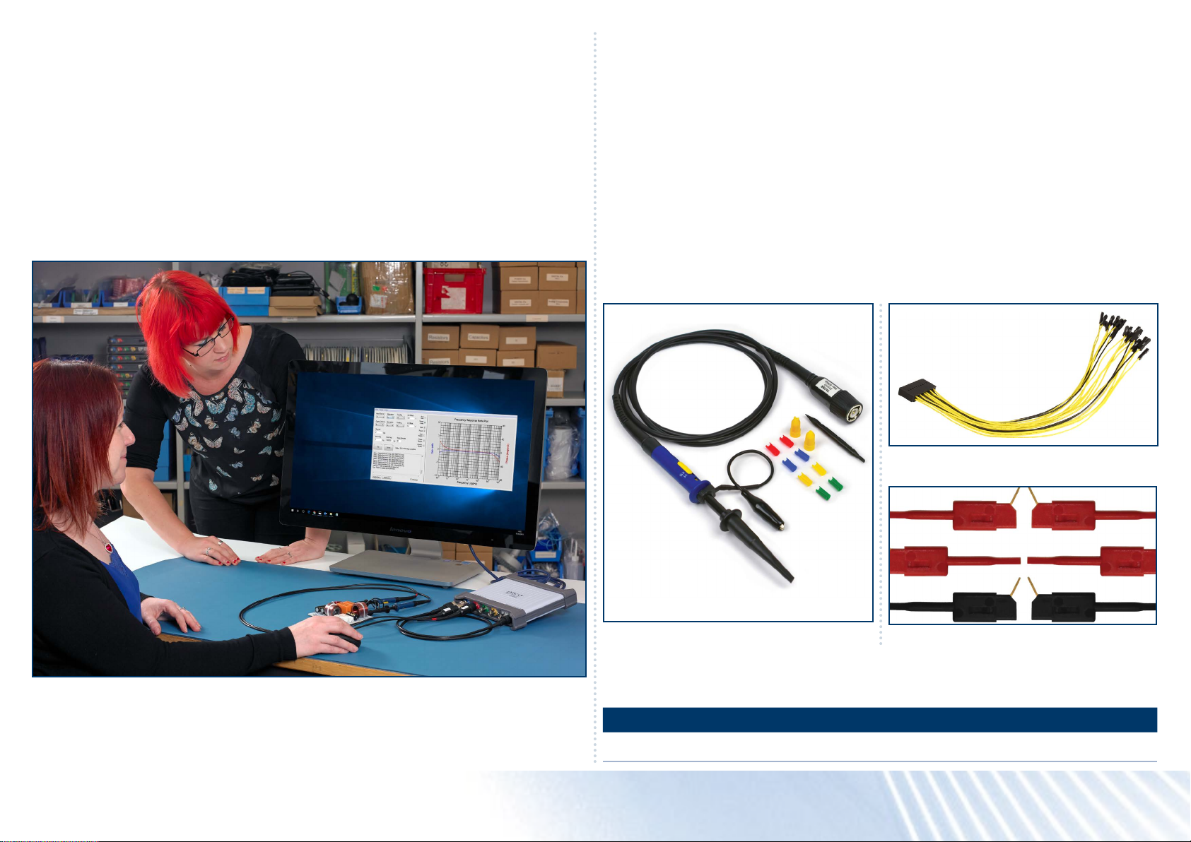
PicoSDK® - write your own apps
Our software development kit, PicoSDK,
allows you to write your own software
and includes drivers for Windows, macOS
and Linux. Example code supplied on our
GitHub organization page shows how to
interface to third-party software packages
such as National Instruments LabVIEW
and MathWorks MATLAB.
Amongst other features, the drivers
support data streaming, a mode that
captures continuous gap-free data directly
to your PC at rates of up to 125 MS/s,
so you are not limited by the size of your
scope’s capture memory. Sampling rates
in streaming mode are subject to PC
specications and application loading.
There is also an active community of
PicoScope6 users who share both code
and whole applications on our Test and
Measurement Forum and the PicoApps
section of the website. The Frequency
Response Analyzer shown here is one of
the most popular of these applications.
Kit contents and accessories
Your PicoScope 5000D Series oscilloscope kit contains the following items:
• PicoScope 5000D Series oscilloscope
• 1 x TA155 Pico blue USB 3 cable 1.8 m
• 60 MHz models: 2/4 x TA375 probes
• 100 MHz models: 2/4 x TA375 probes.
• 200 MHz models: 2/4 x TA386 probes.
• 4-channel models: 1 x PS011 5 V 3.0 A PSU
• MSO models: 1 x TA136 MSO cable
• MSO models: 2 x TA139 set of MSO clips
• Quick start guide
Probes, cables and clips
Your PicoScope 5000D Series oscilloscope kit comes with probes specically trimmed
to match the performance of your oscilloscope.
MSO models are also supplied with an MSO cable and 20 test clips.
• 20-way 25 cm digital MSO cable
• Oscilloscope probe
Part numbers:
60 MHz probe 100 MHz probe 200 MHz probe MSO cable 10 test clips
TA375 TA375 TA386 TA136 TA139
• MSO test clips
PicoScope® 5000D Series oscilloscopes
Page 12
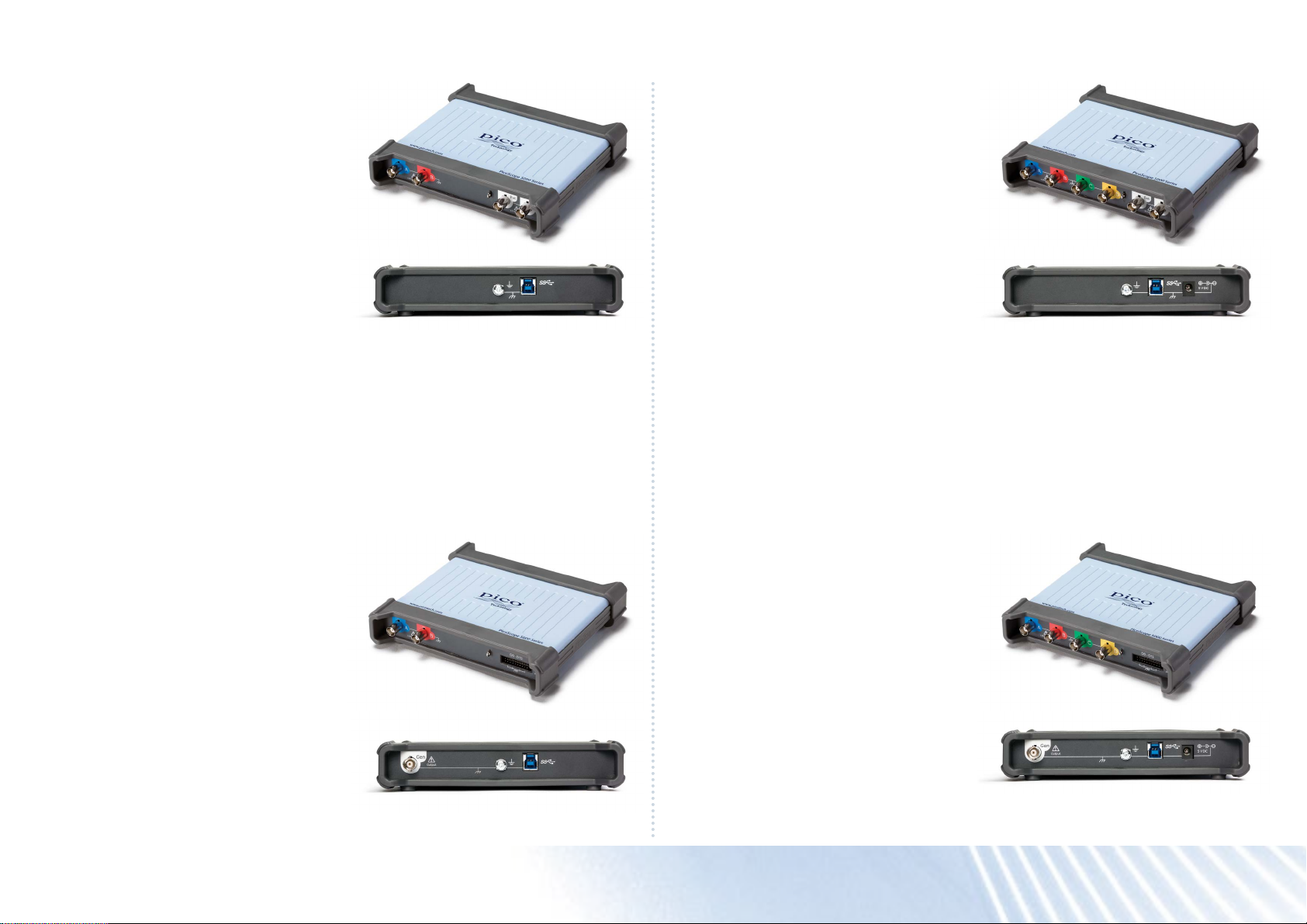
Connections
The front panel of the 2-channel PicoScope
5000D Series oscilloscopes has:
2 x BNC analog input channels
1 x probe compensation pin
1 x BNC external trigger input
1 x BNC AWG/function generator output
The rear panel has:
1 x ground terminal
1 x USB 3.0 port
The front panel of the 4-channel PicoScope
5000D Series oscilloscopes has:
4 x BNC analog input channels
1 x probe compensation pin
1 x BNC external trigger input
1 x BNC AWG/function generator output
The rear panel has:
1 x ground terminal
1 x USB 3.0 port
1 x DC power input
The front panel of the 2-channel PicoScope
5000D MSO Series oscilloscopes has:
2 x BNC analog input channels
1 x probe compensation pin
16 digital inputs
The rear panel has:
1 x BNC AWG/function generator output
1 x ground terminal
1 x USB 3.0 port
The front panel of the 4-channel PicoScope
5000D MSO Series oscilloscopes has:
4 x BNC analog input channels
1 x probe compensation pin
16 digital inputs
The rear panel has:
1 x BNC AWG/function generator output
1 x ground terminal
1 x USB 3.0 port
1 x DC power input
PicoScope® 5000D Series oscilloscopes
Page 13
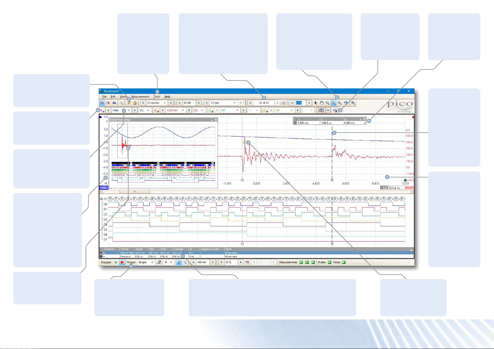
PicoScope 6 software
The display can be as simple or as
advanced as you need. Begin with
a single view of one channel, and
then expand the display to include
any number of live channels, math
channels and reference waveforms.
Auto setup button:
Configures the collection
time and voltage range for
clear display of signals.
Channel options:
Filtering, offset, resolution
enhancement, custom
probes and more.
Oscilloscope controls:
Controls such as voltage
range, scope resolution,
channel enable, timebase
and memory depth.
Movable axes: The
vertical axes can
be dragged up and
down. This feature
is particularly useful
when one waveform
is obscuring another.
There’s also an
Auto Arrange Axes
command.
Tools: Including
serial decoding,
reference
channels, macro
recorder, alarms,
mask limit
testing and math
channels.
Waveform replay tools:
PicoScope 6 automatically
records up to 10,000 of the
most recent waveforms. You
can quickly scan through to
look for intermittent events,
or use the Buffer Navigator to
search visually.
Zoom and pan tools:
PicoScope 6 allows a
zoom factor of several
million, which is necessary
when working with the
deep memory of the
5000D Series scopes.
Signal generator:
Generates standard
signals or arbitrary
waveforms.
Includes frequency
sweep mode.
Ruler legend:
Absolute and
differential ruler
measurements
are listed here.
Rulers: Each axis
has two rulers
that can be
dragged across
the screen to
make quick
measurements
of amplitude,
time and
frequency.
Views:
PicoScope 6
is carefully
designed to
make the best
use of the
display area. You
can add new
scope, spectrum
and XY views
with automatic
or custom
layouts.
Zoom overview: Click
and drag for quick
navigation in zoomed
views.
Trigger toolbar: Quick
access to main controls,
with advanced triggers
in a pop-up window.
Automatic measurements: Display calculated measurements
for troubleshooting and analysis. You can add as many
measurements as you need on each view. Each measurement
includes statistical parameters showing its variability.
Trigger marker: Drag
the yellow diamond to
adjust trigger level and
pre-trigger time.
PicoScope® 5000D Series oscilloscopes
Page 14
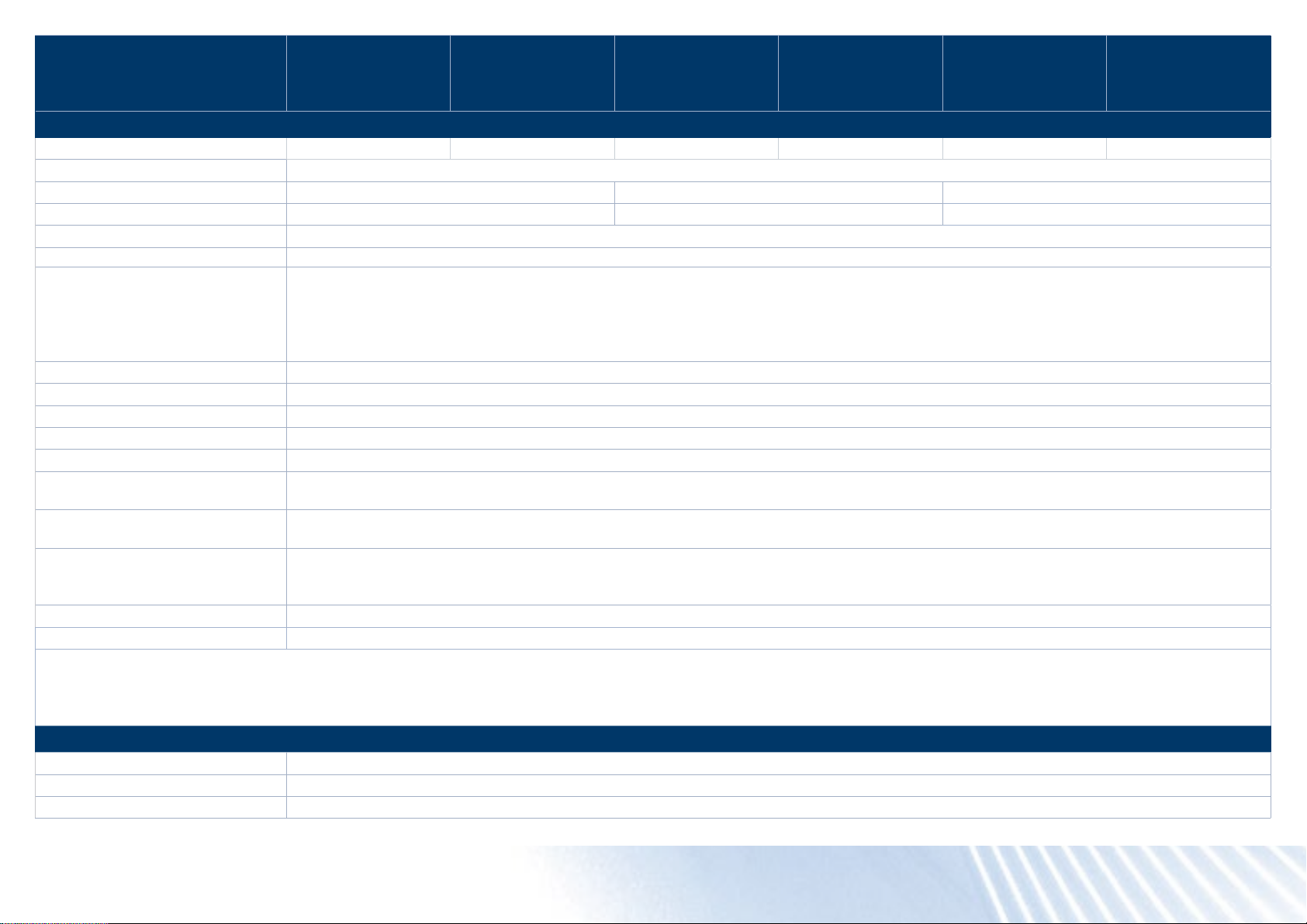
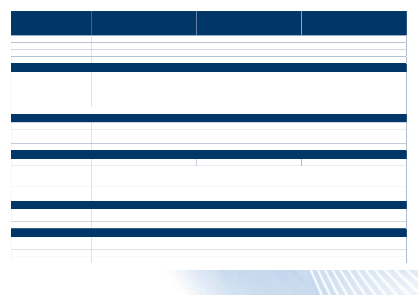
PicoScope 5000D Series
Technical Specications
PicoScope 5242D
and 5242D MSO
2-channel, 60 MHz
PicoScope 5442D
and 5442D MSO
4-channel, 60 MHz
PicoScope 5243D
and 5243D MSO
2-channel, 100 MHz
PicoScope 5443D
and 5443D MSO
4-channel, 100 MHz
PicoScope 5244D
and 5244D MSO
2-channel, 200 MHz
PicoScope 5444D
and 5444D MSO
4-channel, 200 MHz
Vertical (analog channels)
Analog input channels 2 4 2 4 2 4
Input type Single-ended, BNC(f) connector
Bandwidth (–3 dB) 60 MHz 100 MHz
Rise time (calculated) 5.8 ns 3.5 ns
[1]
[1]
200 MHz
1.75 ns
[1]
[1]
Bandwidth limiter 20 MHz, selectable
Vertical resolution
[2]
8, 12, 14, 15 or 16 bits
8-bit mode: < 0.6% of input range
12-bit mode: < 0.04% of input range
[2]
LSB size (quantization step size)
14-bit mode: < 0.01% of input range
15-bit mode: < 0.005% of input range
16-bit mode: < 0.0025% of input range
Enhanced vertical resolution Hardware resolution + 4 bits
Input ranges ±10 mV to ±20 V full scale, in 11 ranges
Input sensitivity 2 mV/div to 4 V/div (10 vertical divisions)
Input coupling AC / DC
Input characteristics 1 MΩ ±1% || 14 ±1 pF
Gain accuracy
Offset accuracy
Analog offset range
(vertical position adjust)
12 to 16-bit modes: ±0.5% of signal ±1 LSB
8-bit mode: ±2% of signal ±1 LSB
±500 µV ±1% of full scale
[3]
Offset accuracy can be improved by using the zero offset function in PicoScope 6.
±250 mV (10, 20, 50, 100, 200 mV ranges)
±2.5 V (500 mV, 1 V, 2 V ranges)
±20 V (5, 10, 20 V ranges)
[3]
[3]
Analog offset control accuracy ±0.5% of offset setting, additional to basic DC offset accuracy
Overvoltage protection ±100 V (DC + AC peak)
[1]
In 16-bit mode, bandwidth reduced to 60 MHz and rise time increased to 5.8 ns.
[2]
On ±20 mV range, in 14 to 16-bit modes, hardware resolution reduced by 1 bit. On ±10 mV range, hardware resolution reduced by 1 bit in 12-bit mode, 2 bits in 14 to 16-bit
modes.
[3]
Between 15 and 30 °C after 1 hour warm-up.
Vertical (digital channels) – D MSO models only
Input channels 16 channels (2 ports of 8 channels each)
Input connector 2.54 mm pitch, 10 x 2 way connector
Maximum input frequency 100 MHz (200 Mbit/s)
PicoScope® 5000D Series oscilloscopes
Page 15
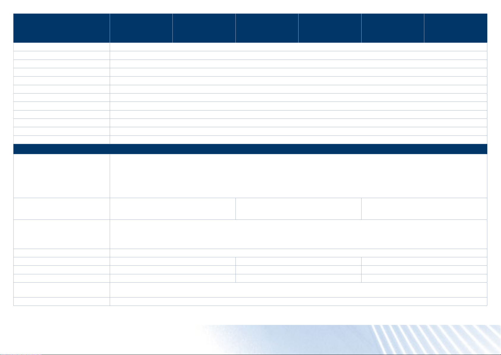
PicoScope 5000D Series
Technical Specications
PicoScope 5242D
and 5242D MSO
2-channel, 60 MHz
PicoScope 5442D
and 5442D MSO
4-channel, 60 MHz
PicoScope 5243D
and 5243D MSO
2-channel, 100 MHz
PicoScope 5443D
and 5443D MSO
4-channel, 100 MHz
PicoScope 5244D
and 5244D MSO
2-channel, 200 MHz
PicoScope 5444D
and 5444D MSO
4-channel, 200 MHz
Minimum detectable pulse width 5 ns
Input impedance 200 kΩ ±2% || 8 pF ±2 pF
Input dynamic range ±20 V
Threshold range ±5 V
Threshold grouping Two independent threshold controls. Port 0: D0 to D7, Port 1: D8 to D15
Threshold selection TTL, CMOS, ECL, PECL, user-dened
Threshold accuracy < ±350 mV including hysteresis
Threshold hysteresis < ±250 mV
Minimum input voltage swing 500 mV peak to peak
Channel-to-channel skew 2 ns, typical
Minimum input slew rate 10 V/µs
Overvoltage protection ±50 V (DC + AC peak)
Horizontal
Maximum sampling rate
Any 1 channel
Any 2 channels
Any 3 or 4 channels
More than 4 channels
8-bit mode
1 GS/s
500 MS/s
250 MS/s
125 MS/s
12-bit mode
500 MS/s
250 MS/s
125 MS/s
62.5 MS/s
14-bit mode
125 MS/s
125 MS/s
125 MS/s
62.5 MS/s
15-bit mode
125 MS/s
125 MS/s
[4]
16-bit mode
”Channel” means any analog channel or 8-bit digital port.
Maximum equivalent sampling rate
(repetitive signals; 8-bit mode only,
2.5 GS/s 5 GS/s 10 GS/s
ETS mode)
Maximum sampling rate
(continuous USB streaming into PC
memory)
[5]
USB 3, using PicoScope 6: 15 to 20 MS/s
USB 3, using PicoSDK: 125 MS/s (8-bit mode) or 62.5 MS/s (12 to 16-bit modes)
USB 2, using PicoScope 6: 8 to 10 MS/s
USB 2, using PicoSDK: ~30 MS/s (8-bit mode) or ~15 MS/s (12 to 16-bit modes)
Timebase ranges (real-time) 1 ns/div to 5000 s/div in 39 ranges
Fastest timebase (ETS) 500 ps/div 200 ps/div 100 ps/div
Buffer memory
Buffer memory
Buffer memory
(continuous streaming)
[6]
(8-bit) 128 MS 256 MS 512 MS
[6]
(≥ 12-bit) 64 MS 128 MS 256 MS
[7]
100 MS in PicoScope 6 software
Waveform buffer (no. of segments) 10 000 in PicoScope 6 software
[4]
62.5 MS/s
PicoScope® 5000D Series oscilloscopes
Page 16
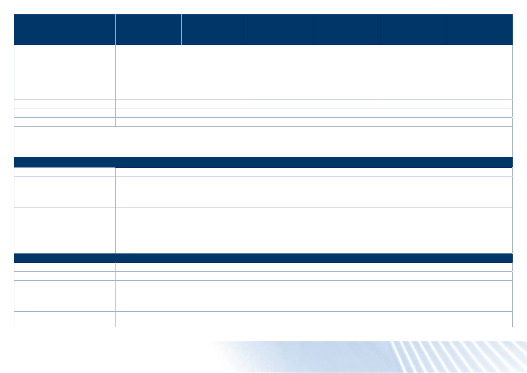
PicoScope 5000D Series
Technical Specications
PicoScope 5242D
and 5242D MSO
2-channel, 60 MHz
PicoScope 5442D
and 5442D MSO
4-channel, 60 MHz
PicoScope 5243D
and 5243D MSO
2-channel, 100 MHz
PicoScope 5443D
and 5443D MSO
4-channel, 100 MHz
PicoScope 5244D
and 5244D MSO
2-channel, 200 MHz
PicoScope 5444D
and 5444D MSO
4-channel, 200 MHz
Waveform buffer (no. of
segments) when using PicoSDK
250 000 500 000 1 000 000
(8 bits)
Waveform buffer (no. of
segments) when using PicoSDK
125 000 250 000 500 000
(12 to 16 bits)
Initial timebase accuracy ±50 ppm (0.005%) ±2 ppm (0.0002%) ±2 ppm (0.0002%)
Timebase drift ±5 ppm/year ±1 ppm/year ±1 ppm/year
Sample jitter 3 ps RMS, typical
ADC sampling Simultaneous on all enabled channels.
[4]
Any number of 8-bit digital ports can be used in 15-bit and 16-bit modes without affecting the maximum sampling rate.
[5]
Shared between enabled channels, PC dependent, available sample rates vary by resolution.
[6]
Shared between enabled channels.
[7]
Driver buffering up to available PC memory when using PicoSDK. No limit on duration of capture.
Dynamic performance (typical, analog channels)
Crosstalk Better than 400:1 up to full bandwidth (equal voltage ranges).
Harmonic distortion
SFDR
8-bit mode: −60 dB at 100 kHz full scale input
12 to 16-bit modes: −70 dB at 100 kHz full scale input
8 to 12-bit modes: 60 dB at 100 kHz full scale input
14 to 16-bit modes: 70 dB at 100 kHz full scale input
8-bit mode: 120 μV RMS
12-bit mode: 110 μV RMS
Noise (on ±10 mV range)
14-bit mode: 100 μV RMS
15-bit mode: 85 μV RMS
16-bit mode: 70 μV RMS
Bandwidth atness (+0.3 dB, −3 dB) from DC to full bandwidth
Triggering (main specications)
Source Analog channels, plus: MSO models: Digital D0 to D15; other models: Ext trigger
Trigger modes None, auto, repeat, single, rapid (segmented memory)
Advanced trigger types (analog
channels)
Trigger types (analog channels,
ETS)
Trigger sensitivity (analog
channels)
Edge, window, pulse width, window pulse width, dropout, window dropout, interval, runt, logic
Rising or falling edge ETS trigger available on ChA only, 8-bit mode only
Digital triggering provides 1 LSB accuracy up to full bandwidth of scope
PicoScope® 5000D Series oscilloscopes
Page 17
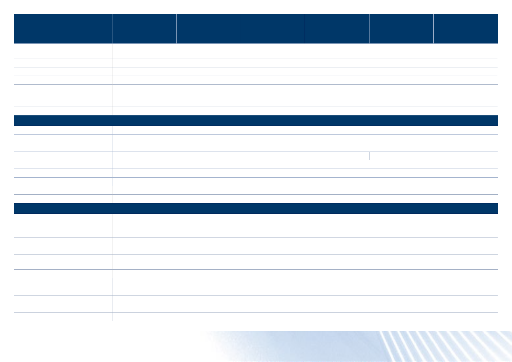
PicoScope 5000D Series
Technical Specications
PicoScope 5242D
and 5242D MSO
2-channel, 60 MHz
PicoScope 5442D
and 5442D MSO
4-channel, 60 MHz
PicoScope 5243D
and 5243D MSO
2-channel, 100 MHz
PicoScope 5443D
and 5443D MSO
4-channel, 100 MHz
PicoScope 5244D
and 5244D MSO
2-channel, 200 MHz
PicoScope 5444D
and 5444D MSO
4-channel, 200 MHz
Trigger sensitivity (analog
channels, ETS)
Trigger types (digital inputs) MSO models only: Edge, pulse width, dropout, interval, logic, pattern, mixed signal
Maximum pre-trigger capture Up to 100% of capture size.
Maximum post-trigger delay Zero to 4 billion samples, settable in 1 sample steps (delay range on fastest timebase of 0 to 4 s in 1 ns steps)
Trigger rearm time
Maximum trigger rate 10 000 waveforms in a 10 ms burst, 8-bit mode
External trigger input – not MSO models
Connector type Front panel BNC(f)
Trigger types Edge, pulse width, dropout, interval, logic
Input characteristics 1 MΩ ±1% || 14 pF ±1.5 pF
Bandwidth 60 MHz 100 MHz 200 MHz
Threshold range ±5 V
External trigger threshold accuracy ±1% of full scale
External trigger sensitivity 200 mV peak to peak
Coupling DC
Overvoltage protection ±100 V (DC + AC peak)
Function generator
Standard output signals Sine, square, triangle, DC voltage, ramp up, ramp down, sinc, Gaussian, half-sine
Pseudorandom output signals
Standard signal frequency 0.025 Hz to 20 MHz
Sweep modes Up, down, dual with selectable start / stop frequencies and increments
Triggering
Output frequency accuracy Oscilloscope timebase accuracy ± output frequency resolution
Output frequency resolution < 0.025 Hz
Output voltage range ±2 V
Output voltage adjustments Signal amplitude and offset adjustable in approx 0.25 mV steps within overall ±2 V range
Amplitude atness < 1.5 dB to 20 MHz, typical
DC accuracy ±1% of full scale
At full bandwidth: typical 10 mV peak to peak
8-bit mode, typical: 1 μs on fastest timebase
8 to 12-bit modes: < 2 μs max on fastest timebase
14 to 16-bit modes: < 3 μs max on fastest timebase
White noise, selectable amplitude and offset within output voltage range.
Pseudorandom binary sequence (PRBS), selectable high and low levels within output voltage range, selectable bit rate up to 20 Mb/s
Can trigger a counted number of waveform cycles or frequency sweeps (from 1 to 1 billion) from the scope trigger, external trigger or from
software. Can also use the external trigger to gate the signal generator output.
PicoScope® 5000D Series oscilloscopes
Page 18
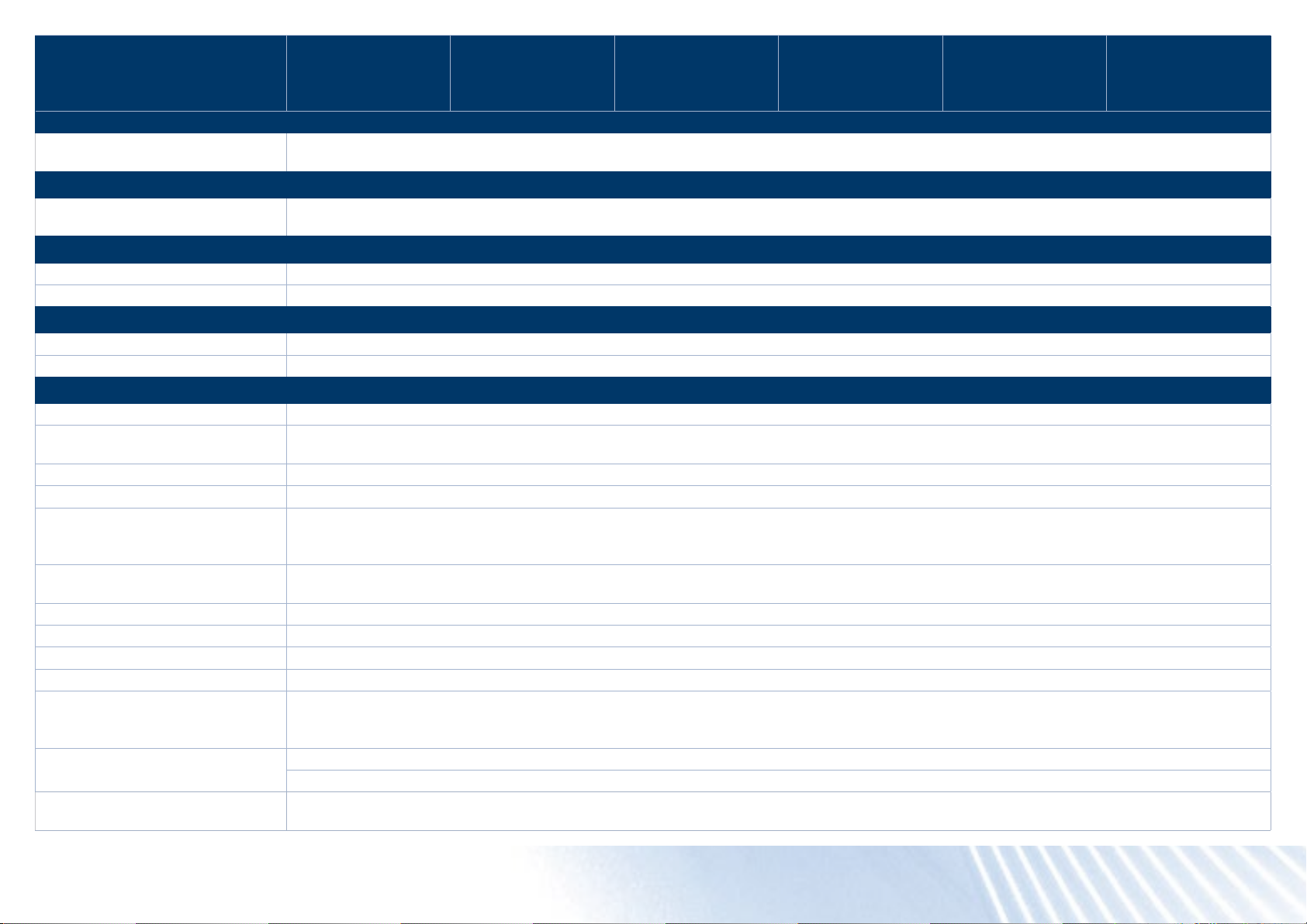
PicoScope 5000D Series
Technical Specications
SFDR > 70 dB, 10 kHz full scale sine wave
Output resistance 50 Ω ±1%
Connector type BNC(f)
Overvoltage protection ±20 V
Arbitrary waveform generator
AWG update rate 200 MHz
AWG buffer size 32 kS
AWG resolution 14 bits (output step size approx 0.25 mV)
AWG bandwidth > 20 MHz
AWG rise time (10% to 90%) <10 ns (50 Ω load)
Other AWG specications including sweep modes, triggering, frequency accuracy and resolution, voltage range, DC accuracy and output characteristics are as function generator.
Probe compensation pin
Output characteristics 600 Ω
Output frequency 1 kHz
Output level 3 V peak to peak, typical
Overvoltage protection 10 V
Spectrum analyzer
Frequency range DC to 60 MHz DC to 100 MHz DC to 200 MHz
Display modes Magnitude, average, peak hold
Y axis Logarithmic (dbV, dBu, dBm, arbitrary dB) or linear (volts)
X axis Linear or logarithmic
Windowing functions Rectangular, Gaussian, triangular, Blackman, Blackman−Harris, Hamming, Hann, at-top
Number of FFT points Selectable from 128 to 1 million in powers of 2
Math channels
Functions
Operands A, B, C, D (input channels), T (time), reference waveforms, pi, D0−D15 (digital channels), constants
Automatic measurements
Scope mode
Spectrum mode Frequency at peak, amplitude at peak, average amplitude at peak, total power, THD %, THD dB, THD+N, SFDR, SINAD, SNR, IMD
Statistics Minimum, maximum, average, standard deviation
PicoScope 5242D
and 5242D MSO
2-channel, 60 MHz
−x, x+y, x−y, x*y, x/y, x^y, sqrt, exp, ln, log, abs, norm, sign, sin, cos, tan, arcsin, arccos, arctan, sinh, cosh, tanh, delay, average, frequency,
derivative, integral, min, max, peak, duty, highpass, lowpass, bandpass, bandstop
AC RMS, true RMS, frequency, cycle time, duty cycle, DC average, falling rate, rising rate, low pulse width, high pulse width, fall time, rise time,
minimum, maximum, peak to peak
PicoScope 5442D
and 5442D MSO
4-channel, 60 MHz
PicoScope 5243D
and 5243D MSO
2-channel, 100 MHz
PicoScope 5443D
and 5443D MSO
4-channel, 100 MHz
PicoScope 5244D
and 5244D MSO
2-channel, 200 MHz
PicoScope 5444D
and 5444D MSO
4-channel, 200 MHz
PicoScope® 5000D Series oscilloscopes
Page 19
PicoScope 5000D Series
Technical Specications
DeepMeasure™
Parameters
Serial decoding
Protocols
Mask limit testing
Statistics Pass/fail, failure count, total count
Mask creation User-drawn, table entry, auto-generated from waveform or imported from le
Display
Interpolation Linear or sin(x)/x
Persistence modes Digital color, analog intensity, custom, fast
General
PC connectivity USB 3.0 SuperSpeed (USB 2.0 compatible)
Power requirements
Dimensions 190 x 170 x 40 mm including connectors
Weight < 0.5 kg
Temperature range
Humidity range
Environment Up to 2000 m altitude and EN61010 pollution degree 2
Safety approvals Designed to EN 61010-1:2010
EMC approvals Tested to EN61326-1:2013 and FCC Part 15 Subpart B
Environmental approvals RoHS and WEEE compliant
Software
PC requirements
Software languages
PicoScope 5242D
and 5242D MSO
2-channel, 60 MHz
Cycle number, cycle time, frequency, low pulse width, high pulse width, duty cycle (high), duty cycle (low), rise time, fall time, undershoot,
overshoot, max. voltage, min. voltage, voltage peak to peak, start time, end time
1-Wire, ARINC 429, CAN & CAN-FD, DCC, DMX512, Ethernet 10Base-T and 100Base-TX, FlexRay, I²C, I²S, LIN, PS/2, MODBUS, SENT, SPI, UART
(RS-232 / RS-422 / RS-485), USB 1.1
2-channel models: powered from single USB 3.0 port
4-channel models: AC adaptor supplied. Can use 2 channels (plus MSO channels if tted) powered by USB 3.0 or charging port supplying 1.2A.
Operating: 0 to 40 °C
15 to 30 °C for quoted accuracy after 1 hour warm-up
Storage: –20 to +60 °C
Operating: 5 to 80 %RH non-condensing
Storage: 5 to 95 %RH non-condensing
PicoScope 6: Windows 7, 8 and 10 (32-bit and 64-bit versions). Beta software also available for 64-bit Linux and macOS.
PicoSDK: Windows 7, 8 and 10 (32-bit and 64-bit versions). Drivers also available for 64-bit Linux and macOS.
Example programs for supported languages and development environments
Processor, memory and disk space: as required by the operating system
Port(s): USB 3.0 or USB 2.0
Simplied and traditional Chinese, Czech, Danish, Dutch, English, Finnish, French, German, Greek, Hungarian, Italian, Japanese, Korean,
Norwegian, Polish, Portuguese, Romanian, Russian, Spanish, Swedish, Turkish
PicoScope 5442D
and 5442D MSO
4-channel, 60 MHz
PicoScope 5243D
and 5243D MSO
2-channel, 100 MHz
PicoScope 5443D
and 5443D MSO
4-channel, 100 MHz
PicoScope 5244D
and 5244D MSO
2-channel, 200 MHz
PicoScope 5444D
and 5444D MSO
4-channel, 200 MHz
PicoScope® 5000D Series oscilloscopes
Page 20
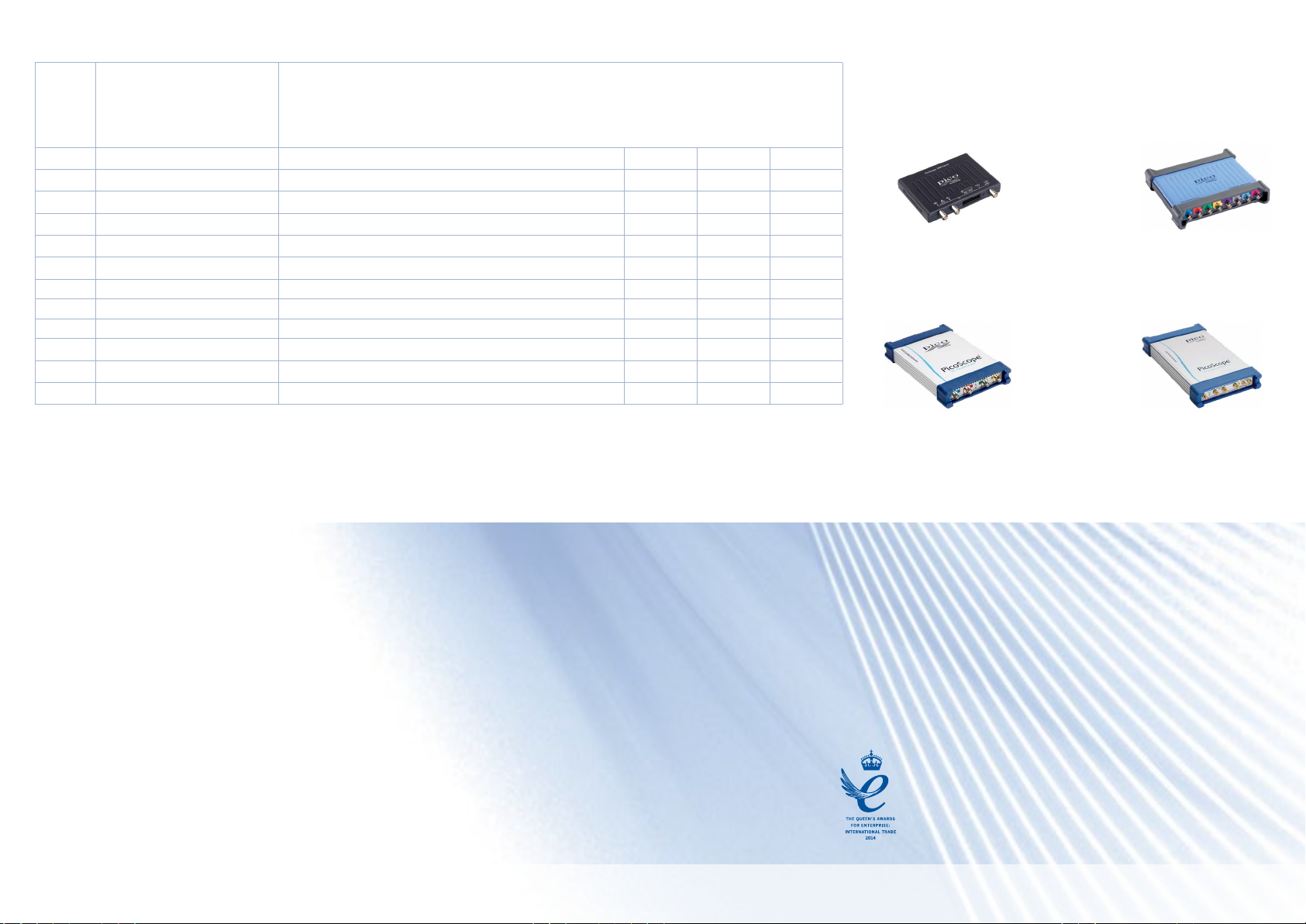
Ordering information
More oscilloscopes in the PicoScope range...
Order
code
Model number Description
PQ143 PicoScope 5242D 60 MHz 2-channel oscilloscope
PQ149 PicoScope 5242D MSO 60 MHz 2-channel mixed-signal oscilloscope
PQ146 PicoScope 5442D 60 MHz 4-channel oscilloscope
PQ152 PicoScope 5442D MSO 60 MHz 4-channel mixed-signal oscilloscope
PQ144 PicoScope 5243D 100 MHz 2-channel oscilloscope
PQ150 PicoScope 5243D MSO 100 MHz 2-channel mixed-signal oscilloscope
PQ147 PicoScope 5443D 100 MHz 4-channel oscilloscope
PQ153 PicoScope 5443D MSO 100 MHz 4-channel mixed-signal oscilloscope
PQ145 PicoScope 5244D 200 MHz 2-channel oscilloscope
PQ151 PicoScope 5244D MSO 200 MHz 2-channel mixed-signal oscilloscope
PQ148 PicoScope 5444D 200 MHz 4-channel oscilloscope
PQ154 PicoScope 5444D MSO 200 MHz 4-channel mixed-signal oscilloscope
* Prices are correct at the time of publication. Sales taxes not included. Please contact Pico Technology for the
latest prices before ordering.
PicoScope
2000 Series
The pocket-sized
PicoScope
PicoScope
6000 Series
High performance
Up to 1 GHz
PicoScope
4000 Series
High precision
12 to 16 bits
PicoScope
9000 Series
Sampling scopes
and TDR to 25 GHz
Errors and omissions excepted. Pico Technology, PicoScope, PicoSDK and FlexRes are registered trademarks of Pico Technology Ltd.
LabVIEW is a trademark of National Instruments Corporation. Linux is the registered trademark of Linus Torvalds, registered in the U.S. and
other countries. macOS is a trademark of Apple Inc., registered in the U.S. and other countries. MATLAB is a registered trademark of The
MathWorks, Inc. Windows and Excel are registered trademarks of Microsoft Corporation in the United States and other countries.
MM093.en-1. Copyright © 2018 Pico Technology Ltd. All rights reserved.
 Loading...