

Page 1
Pick-it L Camera
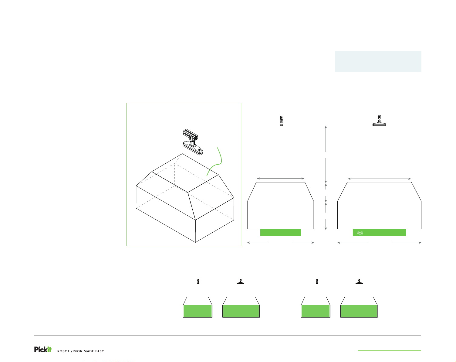
Field of view
Typical usage: Picking of large (minimum
dimensions of 150x150x50mm) objects
from pallets and bins.
To be visible for Pick-it, all
parts or items of interest must
be inside the field of view
(FOV) of the 3D camera.
The region of interest (ROI) can
be seen as a ‘bounding box’
that fits within the FOV of the
3D camera. This box defines
where the actual application
takes place. You can define this
ROI in the Pick-it software.
The possible dimensions of the
ROI depend of the distance
between the 3D camera and
your ROI.
Bringing your application
closer to the camera will
improve image quality and
shrink the potential ROI
volume.
Bringing your application
further from the camera
will lower image quality and
enlarge the potential ROI
volume.
FIELD OF VIEW (FOV)
DIMENSIONS
REGION OF
INTEREST (ROI)
EXAMPLE
APPLICATIONS
Field of view (FOV)
SIDE VIEW FRONT VIEW
1325 mm
1100 mm
425 mm
FOV
625 mm
800 x 1200 x 144 pallet
1500 mm
LARGE BINPALLET
ROI ROIROI ROI
1450 mm
FOV
800 x 1200 x 144 pallet
1900 mm
support.pickit3d.com
Page 2
Pick-it Camera
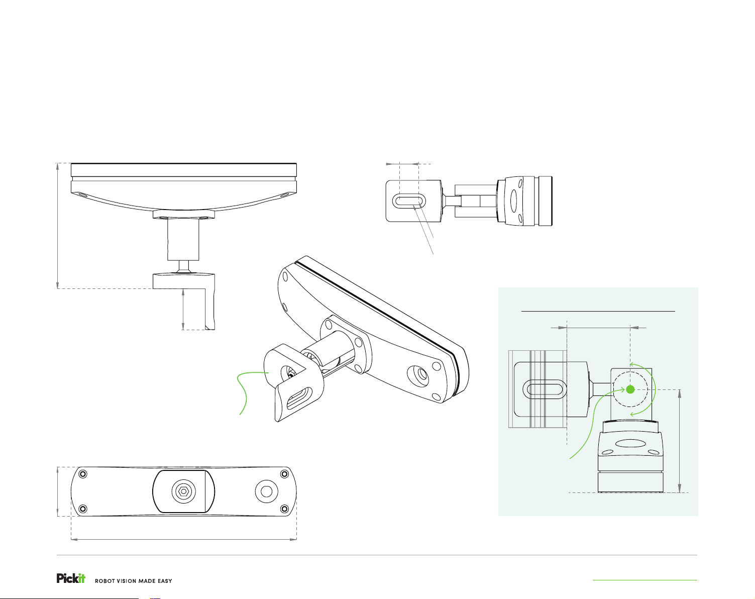
Dimensions
132,50
STRUCTURED LIGHT
43
MOUNTS TO PROFILES
L-BRACKET
20
R7,60
R4.10
BALL JOINT PIVOT (P)
PROFILE
PIVOT CENTER (P)
OF THE BALL JOINT
PROFILE DISTANCE
50,5
180°
P
82,5
FRONT DISTANCE
52
3D CAMERA FRONT
All dimensions in mm
238
support.pickit3d.comsupport.pickit3d.com
Page 3
Bending Radius
Cable
Weight (400g)
Bending Radius
Cable
Weight (400g)
WORKS WITH YOUR ROBOT
Pick-it Facts
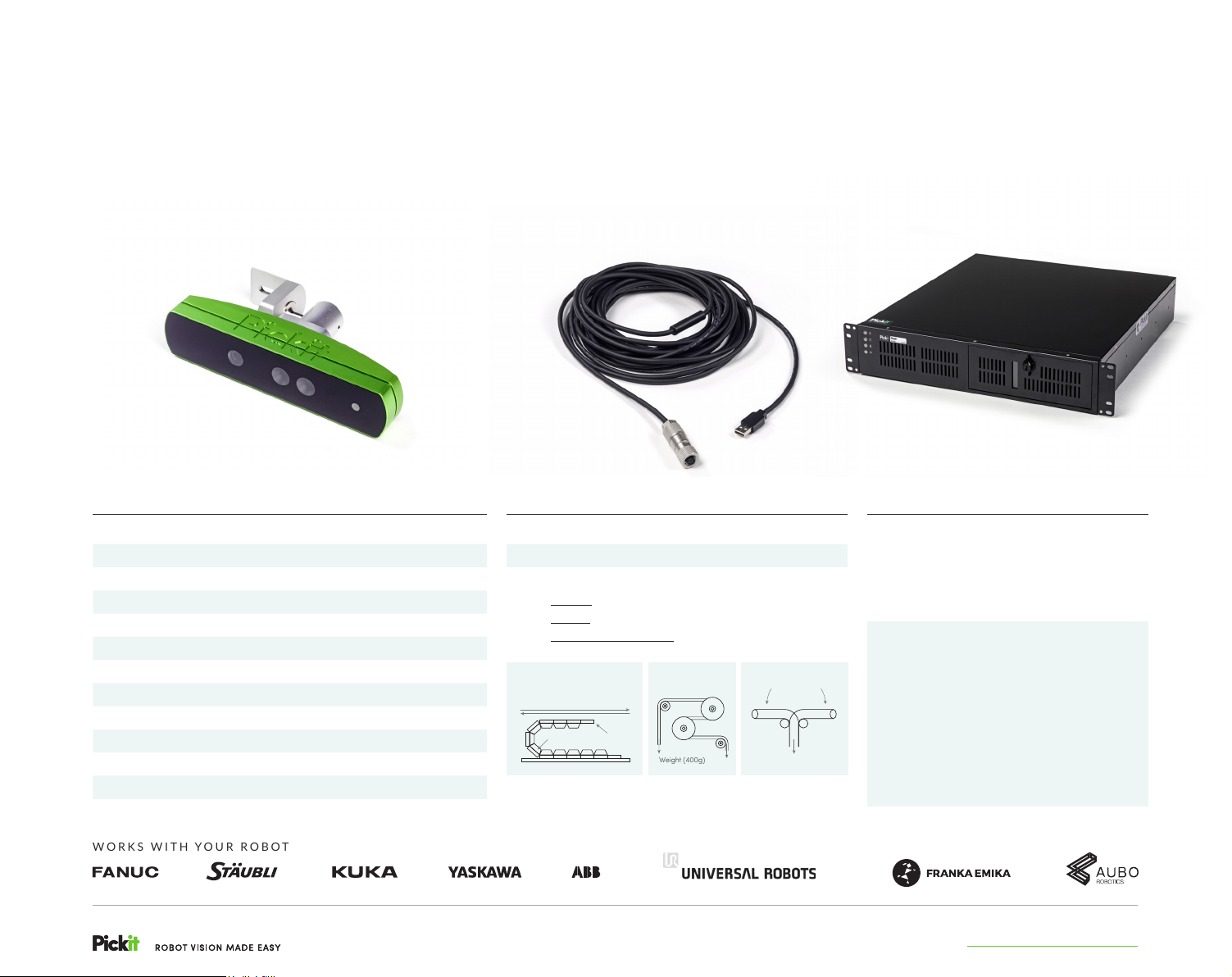
CAMERA TECHNICAL SPECIFICATIONS
3D measurement method Structured light
Image processing speed 30 fps
3D Camera accuracy < 3mm
3D Camera repeatability < 1mm
3D camera weight 1030 g
3D camera connection to PC M12 (USB) - USB3
PC connection to robot TCP/IP over Ethernet
Power supply USB3 5VDC
Temperature 5°C to 40°C
Humidity
IP rating IP55
Vibrations Operating, 2 Grms, 5-500 Hz, 3 axes
Conforms to CE, FCC
95% @ 40°C (non-condensing)
˜
CAMERA CABLE TECHNICAL SPECIFICATIONS
10m
Industrial M12 camera connector
High-Flex / Continuous-Flex
• Type-U (R= 67,5mm - 5.000.000 times)
• Type-S (R= 60mm - 1.000.000 times)
• 90° Tick-Tock bending (R= 60mm - 1.000.000 times)
Moving Directions
Bending Radius
Cable
left + right 90°
Bending
Weight (400g)
PROCESSOR
Power consumption
• While turned o: 25W
• Booting: 100W
• Idle: 60W
• Heavy processing: 130W
Technical specifications
• Processor: 6 cores (12 threads) at 3.7 Ghz
• 19 inch server: rack compatible (2U)
• Temperature: -20°C to 70°C
• Vibrations: Operating, 5 Grms, 5-500 Hz,
3 axes
• IP rating: IP54
• Power supply: 9-32V DC 160W
• Humidity: ˜95% @ 40°C (non-
condensing)
support.pickit3d.comsupport.pickit3d.com
Page 4
i
!
!
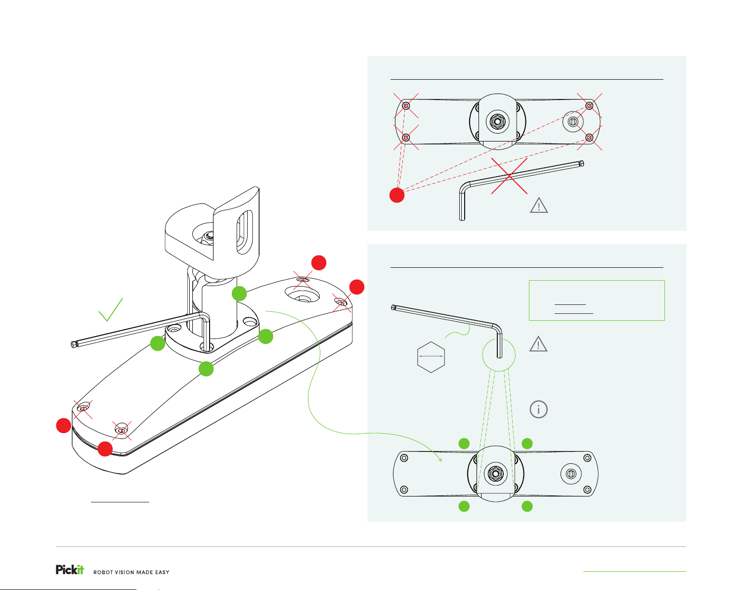
Ball Joint
Tension
4 CALIBRATION BOLTS
!
4 TENSIONING BOLTS
Warranty lost when seal broken.
Do not alter calibration bolt tension!
!
3
1
4
2
!
4 mm
ALLEN KEY
HEXAGONAL SIZE
!
!
1
Nominal Bolt Tension Guidelines
• Fixed joint (immobilized) = 2 Nm
• Flexible joint (mobile) = 0,75 Nm
Gradually adjust the tensioning
bolts of the ball joint in small
steps, following the x-pattern, as
indicated by the numbers in the
figure left, until the recommended
tension is reached per bolt.
Follow the nominal bolt tension
guidelines when adjusting the
tensioning bolts of the ball joint to
alter the joint’s clamping force.
3
Adjust the 4 tensioning bolts as indicated at the right to alter
the ball joint tightness and obtain a fixed joint or a flexible joint
depending your application and needs.
4
2
support.pickit3d.com
Page 5
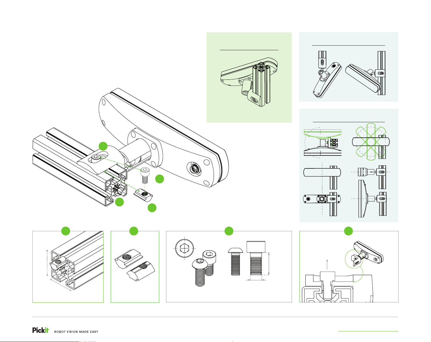
Stationary
Mounting
SOFTWARE SUPPORTS ON-ROBOT MOUNTING
AND STATIONARY MOUNTING
4
RELEASE & LOCK
BALL JOINT
Tool-free 3D camera
positioning in any angle
PROFILE MOUNTING
SIDEEND
2-AXES POSITIONING
360°
180°
3
1
2
1
W
PROFILE W
20 mm > + 45 mm
Profile type shown above is for illustrative purposes only. A wide range of profile types is supported by the L-bracket. Contact us for further info.
W
*
2
T-SLOT PROFILE NUT
M8 - M6
M6-M8 HEX SOCKET @ L 16 MM
ISO 4762, Cap Head
3
M6-M8
M6-M8 HEX SOCKET @ L 16 MM
ISO 7380, Button Head
16
AXIS 1
2 INDEPENDENT AXES
4
F
support.pickit3d.com
AXIS 2
L-BRACKET
Page 6
i
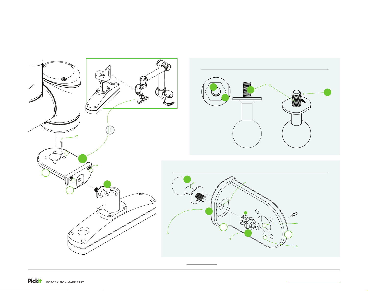
On-Robot Mounting
SOFTWARE SUPPORTS ON-ROBOT MOUNTING AND STATIONARY MOUNTING
ROBOT
ADAPTOR PLATE
Mounts to Robot.
5a
*
LOCK PIN
ON-ROBOT MOUNTING
ADAPTOR SET
b
5
a
a
5b
ASSEMBLY HOLES
M5 HEX SOCKET @ L 16 MM
ISO 7380, Button Head
L-BRACKET
Replace L-Bracket by ‘On-Robot
Mounting Adaptor Set’
(5 = 5a + 5b + OPTIONAL 5c) to mount
the 3D camera onto a robot.*
1
THREADED BALL JOINT ROD
*
THREADED
1
BALL JOINT ROD
THREADED BALL JOINT ROD
External Screw Thread
Type ISO M8 @ L 15 MM
1
1
3
ON-ROBOT MOUNTING ADAPTOR SET
BALL JOINT ROD
MOUNTING HOLE
M8 SAFETY NUT
ISO 10511
3
3D CAMERA ADAPTOR PLATE
Mounts to Threaded Ball Joint Rod.
5
3D CAMERA ADAPTOR PLATE
ON-ROBOT MOUNTING ADAPTOR SET
Incl. 5a : Robot Adaptor Plate
5b : 3D Camera Adaptor Plate
5c : optional flange adapter
*
Robot shown is for illustrative purposes only. A wide range of robot flange types is supported. Contact [email protected] for further info.
5b
M8 SAFETY NUT
ISO 10511
! Optional: Toothed Lock Washer
!
c
3
b
LOCK PIN
FLANGE ADAPTER
RECEIVER
5a
ROBOT ADAPTOR PLATE
LOCK PIN HOLE
support.pickit3d.com
 Loading...