

Page 1
Art.-Nr.:
M O D E L L B A U
ALL BALSA - PLY WOOD CONSTRUCTION.
COVERED IN A HEAT - SHRINK FILM WITH PRINTED
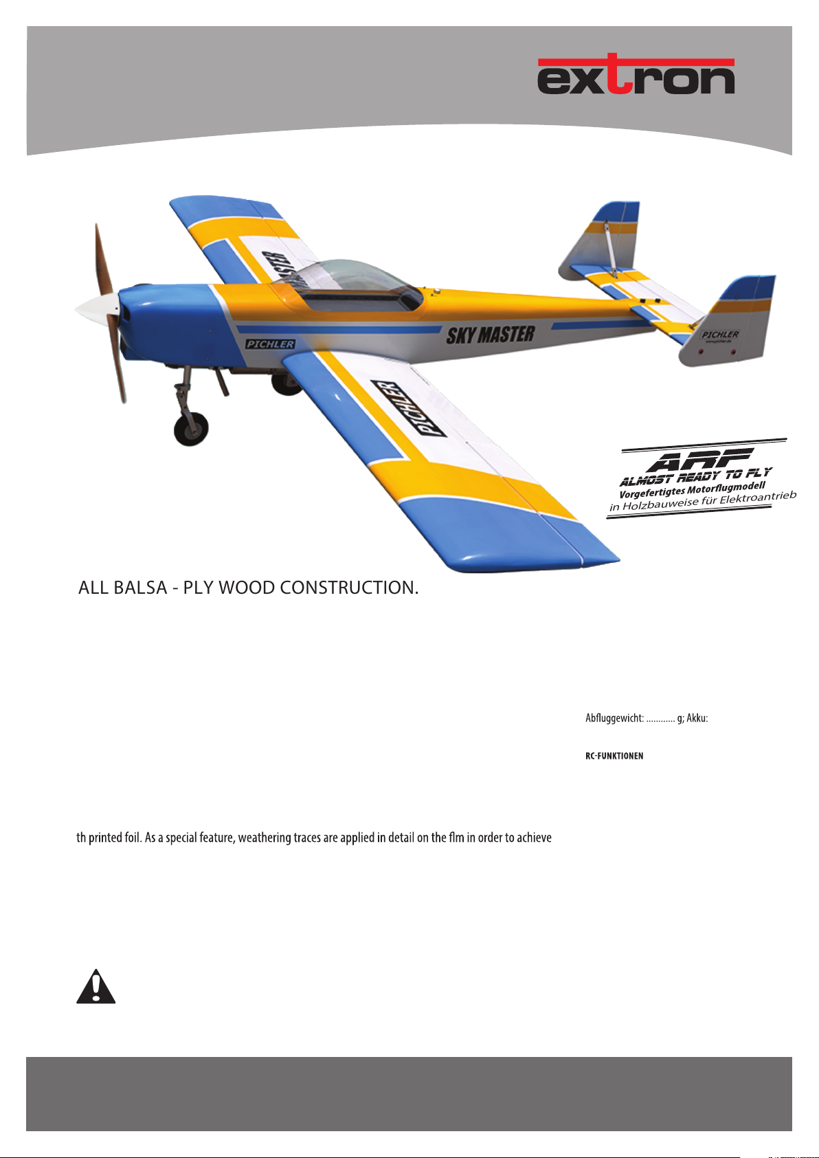
SKY MASTER
Die SKY MASTER ist komplett in Balsa-Sperrholzbauweise aufgebaut. Die leichten Holzteile sind fertig mit
bedruckter Folie bespannt. Als Besonderheit sind auf der Folie Witterungsspuren detailgetreu aufgebracht. Alle Holzteile sind lasergeschnitten und bestechen durch perfekte Passgenauigkeit. Der geräumige Rumpf bietet viel Platz für den Einbau des Antriebs und der RC-Anlage. Die Motorhaube und die
Radverkleidungen sind aus GfK gefertigt und bereits lackiert. Die Pilotenfgur vollendet den perfekten SaleLook der SKY MASTER.
The SKY MA STER is built entirely in a balsa plywood construction. The light wooden parts are fnished wi-
the "used look". All wooden parts are laser-cut and impress with perfect ftting accuracy. The large fuselage provides plenty of space for the installation of the drivetrain and the RC system. The cowling and the
wheelpants are made of FRP and are already painted. The pilot fgure completes the perfect scale look of
the SKY MASTER.
in Holzbauweise für Elektroantrieb
TECHNISCHE DATEN
Spannweite: 2500 mm; Länge: 1855 mm;
............ V;
RC-Ausrüstung: ............ Kanäle/ Servos.........
Seiten-, Höhen-, Querruder, Motor.
SPECIFICATIONS
Wingspan: 2500 mm; Length: 1855 mm;
Weight approx: ................. g; Battery: ............ V;
Radio: ............ channels / Servos.............
RC-Functions
Elevator, Rudder, Aileron, Motor
Achtung: Kein Spielzeug! Für Jugendliche unter 14 Jahren nur unter Aufsicht Erwachsener geeignet.
Warning: This is not a toy! Suitable for young people under the age of 14 with adult supervision.
www.extron-modellbau.de
BAUANLEITUNG / INSTRUCTION MANUAL
Page 2

1. INHALTSVERZEICHNIS / CONTENT
1. Inhaltsverzeichnis / Content
2. Sicherheitshinweise / Safety Instructions
3. Erforderliches Zubehör / Required Accessories
4. Montage / Assembly
5. Hinweise zur Bedienung / How To Use
6. Ersatzteile / Spare Parts
7. Service & Gewährleistung / Service & Warranty
2
MODE L LB AU
Art.-Nr. / Item-No.
Page 3

2. SICHERHEITSHINWEISE / SAFETY INSTRUCTIONS
ALLGEMEINE SICHERHEITSHINWEISE FÜR MODELLE MIT ELEKTROANTRIEB
• Achtung: Kein Spielzeug! Für Jugendliche unter 14 Jahren nur unter Aufsicht Erwachsener geeignet.
• Verwenden Sie das fertige Modell ausschließlich gemäß seiner vorgesehenen Bestimmung, wie unter dem Kapitel „Hinweise zur
Bedienung“ in der Bauanleitung / Bedienungsanleitung erläutert.
• Montieren Sie das Modell grundsätzlich nur nach der Bauanleitung / Bedienungsanleitung zusammen. Nehmen Sie Umbauten nur vor
unter Verwendung von empfohlenen original Ersatz- und Zubehörteilen aus dem Hause extron Modellbau.
• Beachten Sie stets die Gebrauchsanweisung anderweitig zur Anwendung kommender Komponenten (Regler, Akku, Fernsteuerung etc).
• Die Inbetriebnahme ist nicht eher gestattet, bis das Modell laut vorliegender Bauanleitung komplett montiert ist.
• Überprüfen Sie vor der Inbetriebnahme des Modelles die Funktionssicherheit.
• Betreiben Sie das Modell nur dort, wo sich keinerlei Personen oder Tiere aufhalten und eine Beschädigung anderer Güter auszuschließen
ist. Handeln Sie eigenverantwortlich und überprüfen Sie das gewählte Gelände vor Inbetriebnahme des Modells auf seine Eignung.
• Betreiben Sie das Modell NIEMALS auf öentlichen Straßen oder in der Nähe von Flugplätzen.
• Stoppen Sie das Modell unverzüglich bei einer Störung und beseitigen Sie sofort die Ursache.
• Berühren Sie keine rotierenden und/oder heißen Motorteile während des Betriebs oder der Abkühlphase.
• Warten Sie Ihr Modell nach jedem Einsatz und ersetzen Sie Verschleißteile, um einen sicheren Betrieb zu gewährleisten.
• Fassen Sie das Modell währ
• Bedenken Sie, daß Kunststoteile bei niedrigen Außentemperaturen in Ihrer Schlagzähigkeit nachlassen können, das heißt,
die Belastungsfähigkeit sinkt.
• Sofern Sie nicht über ausreichende Kentnisse im Umgang mit Funktionsmodellen verfügen, wenden Sie sich an einen
erfahrenen Modellsportler oder Modellbauclub.
• Schützen Sie sich bei Testläufen vor eventuell durch rotierende Teile aufgewirbelten Schmutz bzw. Steinchen.
• Schützen Sie alle elektrischen Komponenten vor Wasser und Fremdkörpern.
• Sorgen Sie dafür, dass der Motor nicht überlastet oder blockiert wird.
• Lassen Sie den Motor und den Akku nach dem Betrieb ausreichend abkühlen.
end und nach dem Betrieb stets so an, dass Sie keinesfalls mit Teilen des Antriebs in Berührung kommen.
• Laden und entladen Sie Ihre Akkus sorgfältig und achten Sie darauf, dass Akkus und Anschlusskabel keinerlei Beschädigungen aufweisen.
• Schließen Sie den Akku niemals "kurz" durch Zusammenführen des Plus- und Minuspols.
• Verlegen Sie die Kabel im und am Modell so, dass diese nicht in oder an rotierende oder heiße Teile geraten.
Art.-Nr. / Item-No.
www.extron-modellbau.de
3
Page 4

2. SICHERHEITSHINWEISE / SAFETY INSTRUCTIONS
GENERAL SAFETY INSTRUCTIONS FOR ELECTRIC MODELS
• This is not a toy! Suitable for young people under the age of 14 with adult supervision.
• Use the model accordingly to chapter "How To Use" in this instruction manual.
Assemble the model accordingly to this instruction manual. Do not alter or modify the model. Only use parts that are ofcially
•
recommended by extron Modellbau.
• Always pay close attention to the manuals that are included to accessory parts (radio system, speed controller, battery etc.).
•
Do not fly the model before you have fnished the assembly completely according to this manual.
•
Before you fly, check all functions of the model carefully.
Never fly your model near other human beings, animals or other obstacles. You are responsible for flying the model, so
•
you have to check carefully your flight area.
• NEVER use your model on public streets or near public airports.
•
Stop flying immediately if you realize any radio interference.
• Do not touch any moving or hot motor parts during action! Let all components cool down before you handle them.
Check your model carefully after each flight. Replace parts if they are worn out or if they are defective.
•
• Keep your hands out of reach from rotating or hot parts of the model.
• Keep in mind that plastic parts easily break under cold temperature conditions.
•
If you are a novice in flying you should ask experienced pilots for assistance during your frst flights.
• Protect yourself from dust and other small things when you test run your propeller drive on the ground.
• Keep all electronic components dry and clean!
• Take care that your motor does not get overload or gets blocked under full power.
• Let the motor cool down after restarting the model again.
• Charge your batteries carefully. Always watch the charging process and make sure all connectors are in good conditions.
• Do not shorten the battery by connecting the pluspole with the minuspole directly!
• Make sure tha
4
t the wires do not touch rotating or hot parts of the model.
MODE L LB AU
Art.-Nr. / Item-No.
Page 5
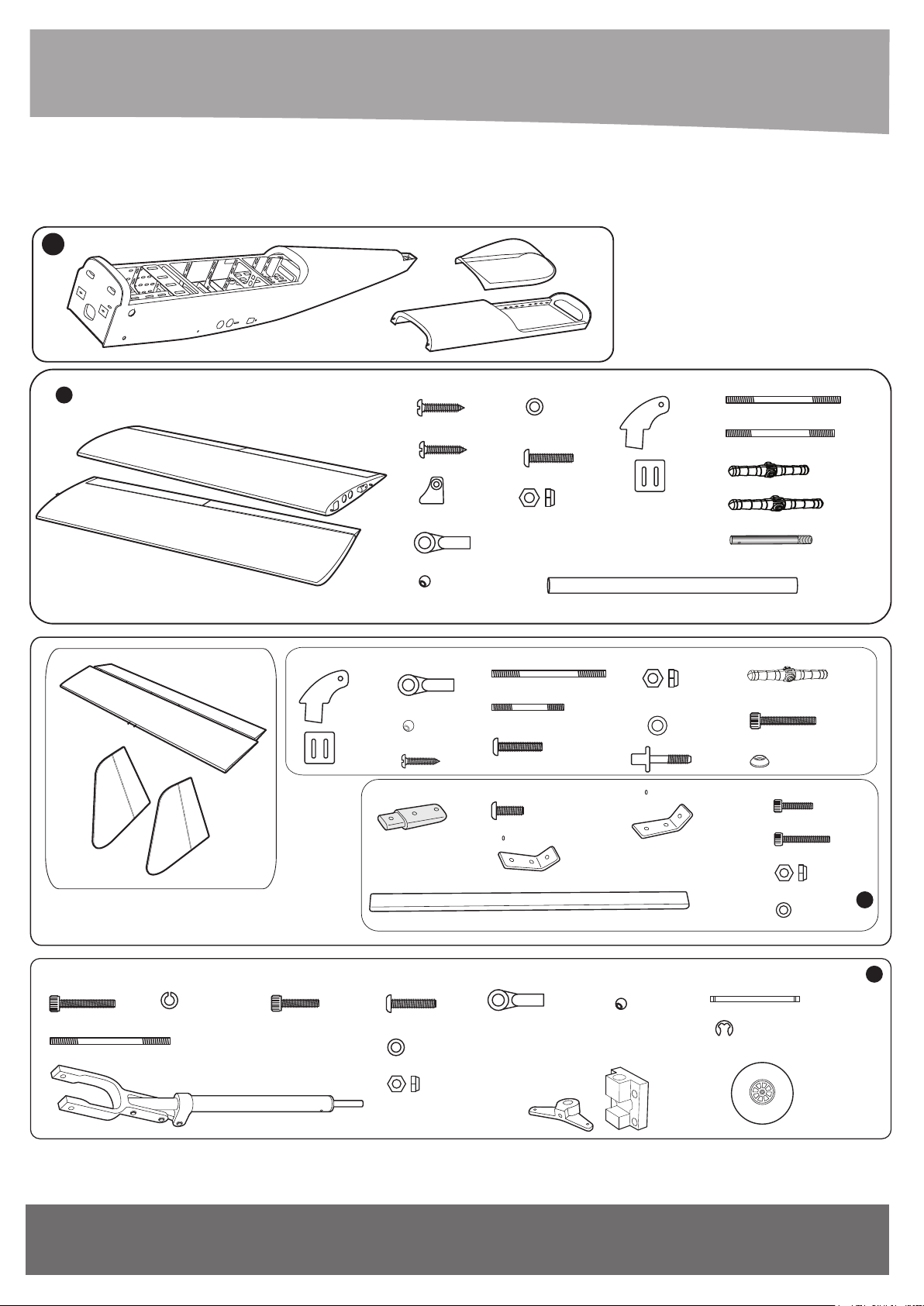
3. ERFORDERLICHES ZUBEHÖR / REQUIRED ACCESSORIES
1: Fuselage set(1a: Canopy; 1b: Hatch). 2: Wing set.
3: Horizontal stabilizer & Vertical stabilizer set. 4: Nose gear set . 5: Main gear set. 6: Cowling set.
7: Fuel tank set. 8: Engine set. 9: Spinner set. 10: CG set.
1
1b
11: Tow Screw.
1a
2
2x10mm Tp Screw
- - - 16
3x12mm Tp Screw
- - - 4
Horn Flap
- - - 2
Ball Link
- - - 8
Horn
Aluminium Ball
Ball Link
- - - 6
Aluminium Ball
2x10mm Tp Screw
- - - 3
Plastic Strut Attachment
132mm Aluminium Strut
- - - 8
- - - 6
- - - 6
- - - 12
- - - 4
3mm Flat Washer
- - - 4
3x12mm Button Head
Cap Screw
3mm Lock Nut
2.6x40mm Push rod Rudder
2.6x mm Push rod Elevator
3x12mm Button Head Cap Screw
3x6mm Button Head Cap Screw
42
Aluminium Strut Attachment
- - - 8
- - - 6
Ø32 -832mm Aluminium Tube
- - - 6
- - - 4
- - - 2
Horn Aileron
3mm Lock Nut
- - - 2
3mm Flat Washer
- - - 1
6x45mm Plastic Screw
Aluminium Strut Attachment
57
2.6x70mm Push rod Aileron
- - - 4
2.6x60mm Push rod Flap
44mm Pinned Hinge Aileron
- - - 2
67mm Pinned Hinge Flap
Aluminium
- - - 6
- - - 3
- - - 2
- - - 2
- - - 2
- - - 1
44mm Pinned Hinge
4x25mm
Socket Head Cap Screw
4mm aluminum Washer
- - - 4
3x20mm Socket Head Cap Screw
3x35mm Socket Head Cap Screw
3mm Lock Nut
- - - 4
3mm Flat Washer
- - - 8
- - - 2
- - - 2
- - - 8
- - - 8
- - - 4
- - - 11
- - - 4
- - - 2
- - - 2
3
4x20mm
Socket Head Cap Screw
2.6x177mm Push rod nose gear
Nose Strut
4mm Spring Washer
- - - 4
Art.-Nr. / Item-No.
- - - 2
- - - 4
4x10mm
Socket Head Cap Screw
- - - 1
3x12mm
Button Head Cap Screw
3mm Flat Washer
- - - 4
3mm Lock Nut
- - - 4
- - - 1
Ball Link
- - - 4
Aluminium Nose Wheel Steering Arm
and Mount Set
www.extron-modellbau.de
- - - 4
Aluminium Ball
- - - 4
- - - 1
6x54mm Wheel axle
E - clip
100mm Wheel
4
- - - 1
- - - 2
- - - 1
5
Page 6
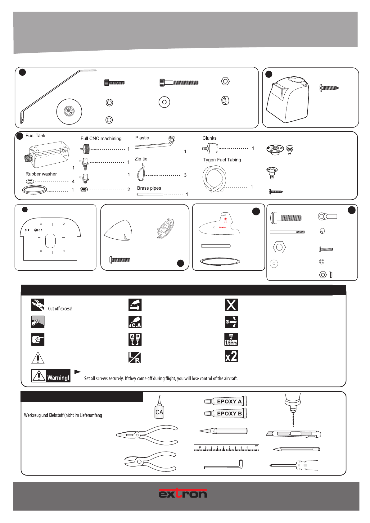
5
Main gear 5x20mm Socket Head Cap Screw
- - - 2
115mm Wheel
- - - 2
- - - 6
5mm Spring Washer
- - - 6
5mm Flat Washer
- - - 6
6x55mm Socket Head Cap Screw
6mm Flat Washer
- - - 8
6mm Hex Nut
- - - 2
6mm Plastic Washer
- - - 4
- - - 2
Cowling
6
3x12mm Tp Screw
- - - 4
- - - 1
7
8
700cc
Mounting pattern of plywood engine
- - - 1
86mm Spinner Cap
- - - 1
3x8mm Button Head Cap Screw
- - - 4
86mm Back Plate
- - - 1
Ø 12x100mm Aluminium Tube
2000mm Wire
9
ERKLÄRUNG DER SYMBOLE / EXPLANATION OF SYMBOLS
Überschuss abschneiden!
Markierte Fläche abschneiden!
Cut the marked area!
Schraubensicherung verwenden!
Use Screw Cement!
Mit Sekundenkleber verkleben!
Use Cyano Glue!
Plate of plywood
Magnetic Anodized Fuel Dot
Alu. Anodized Fuel Vent Line Plug
- - - - - 1
2x5mm Tp Screw
- - - 9
10
- - - 2
Tow Screw
2.6x80mm Push rod
8mm Hex Nut
- - - 1
- - - 1
8mm Flat Washer
Nicht im Lieferumfang enthalten!
Not included!
Auf Leichtgängigkeit achten!
Move freely, NO binding!
- - - - - 1
- - - 1
- - - 1
- - - 1
- - - 1
Ball Link
11
- - - 1
Aluminium Ball
- - - 1
3x12mm
Button Head Cap Screw
- - - 1
3mm Flat Washer
- - - 1
3mm Lock Nut
- - - 1
Genau beachten!
Notice!
Achtung!
Attention!
Schrauben gut festziehen! Falls sich die Verbindung im Flug löst, gerät das Modell außer Kontrolle!
WERKZEUGE / TOOLS
Für die Montage benötigen Sie das nebenstehende
enthalten).
For assembly, you will need the shown tools and
glue (not included).
6
Mit Epoxydharz verkleben!
Use Epoxy Glue!
Eine linke und eine rechte Seite bauen!
Build a left and a right side!
M O DE L L B AU
Loch bohren mit dem dargestellten Durchmesser.
Drill a hole with the shown diameter
Vorgang x-mal wiederholen.
Repeat this step.
Art.-Nr. / Item-No.
Page 7
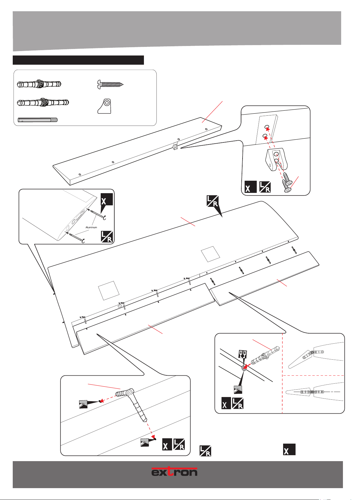
4. MONTAGE / ASSEMBLY
67mm
8
QUERRUDER & ??? / AILERONS & FLAPS
44mm Pinned Hinge Aileron
67mm Pinned Hinge Flap
Aluminium
ANSICHT VON UNTEN
BOTTOM VIEW
- - - 8
- - - 8
- - - 4
3x12mm Tp Screw
- - - 4
Horn Flap
- - - 2
2
Flap
3x12mm
Tp Screw
2
Left Wing
Flap
44mm
8
Eine linke und eine rechte Seite bauen!
Build a left and a right side!
Aileron
Vorgang x-mal wiederholen.
8
Repeat this step.
Art.-Nr. / Item-No.
MOD E LL BA U
7
Page 8
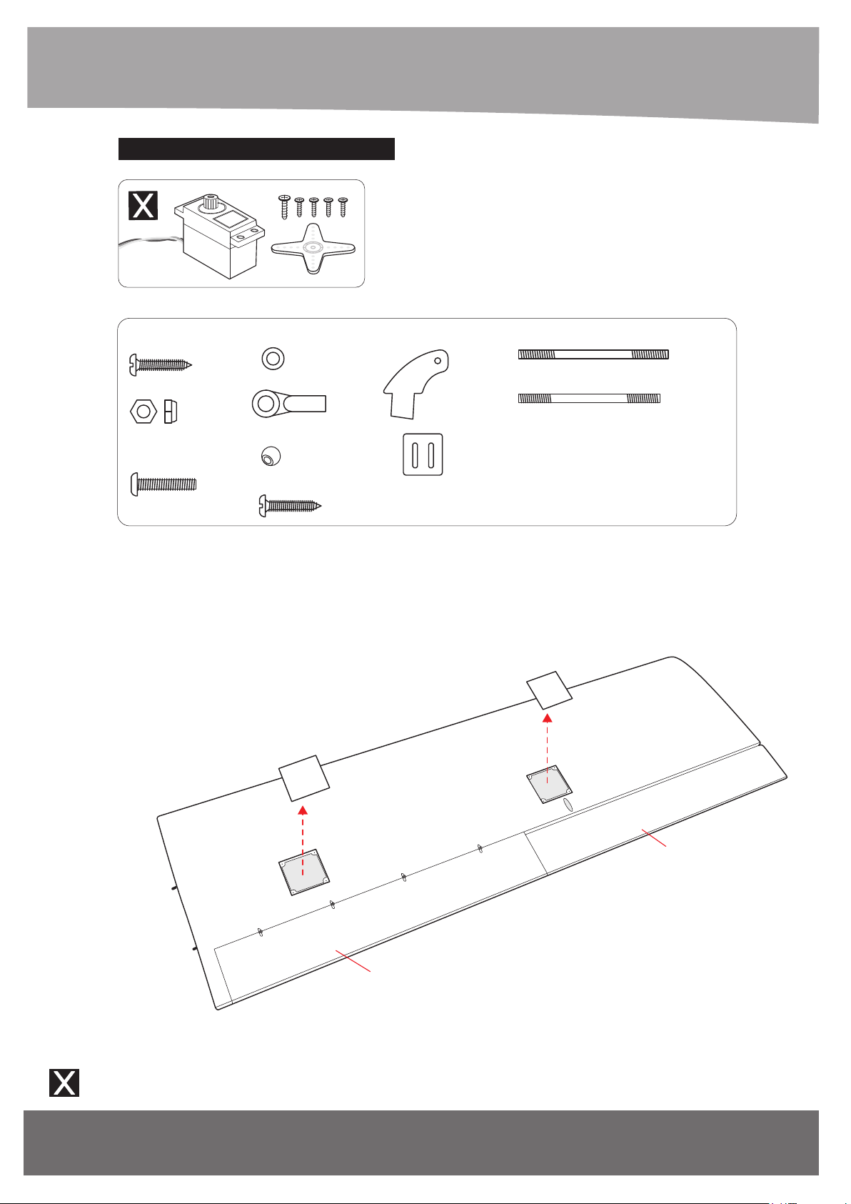
QUERRUDER SERVOS / AILERON SERVOS
2x10mm Tp Screw
- - - 16
3mm Lock Nut
- - - 6
3x12mm Button Head
Cap Screw
- - - 8
ANSICHT VON UNTEN
BOTTOM VIEW
3mm Flat Washer
- - - 4 - - - 4
Ball Link
- - - 8
Aluminium Ball
- - - 8
3x12mm Tp Screw
- - - 4
Horn Aileron
2.6x70mm Push rod Aileron
- - - 2
2.6x60mm Push rod Flap
- - - 2
- - - 2
Nicht im Lieferumfang enthalten!
Not included!
8
Flap
www.extron-modellbau.de
Aileron
Art.-Nr. / Item-No.
Page 9
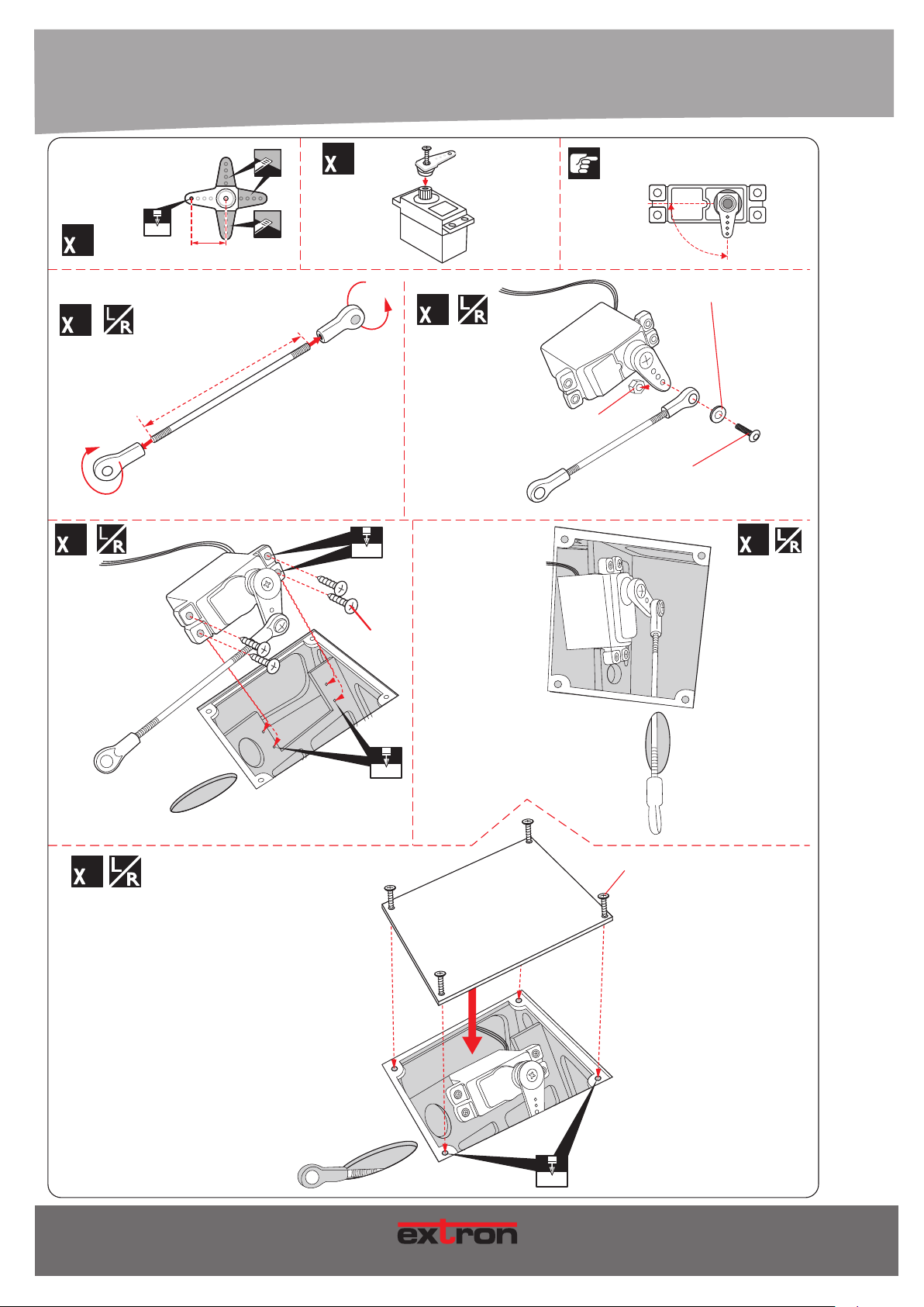
4. MONTAGE / ASSEMBLY
For Aileron Servo
2
2
2
2 mm
approx.16mm
2.6x70mm
2
1.5mm
2
3mm Lock Nut
o
90
3mm Flat Washer
3x12mm Button Head
Cap Screw
2
2
Screw
2mm
2x10mm
Tp Screw
Art.-Nr. / Item-No.
1.5mm
9
MODE L LB AU
Page 10
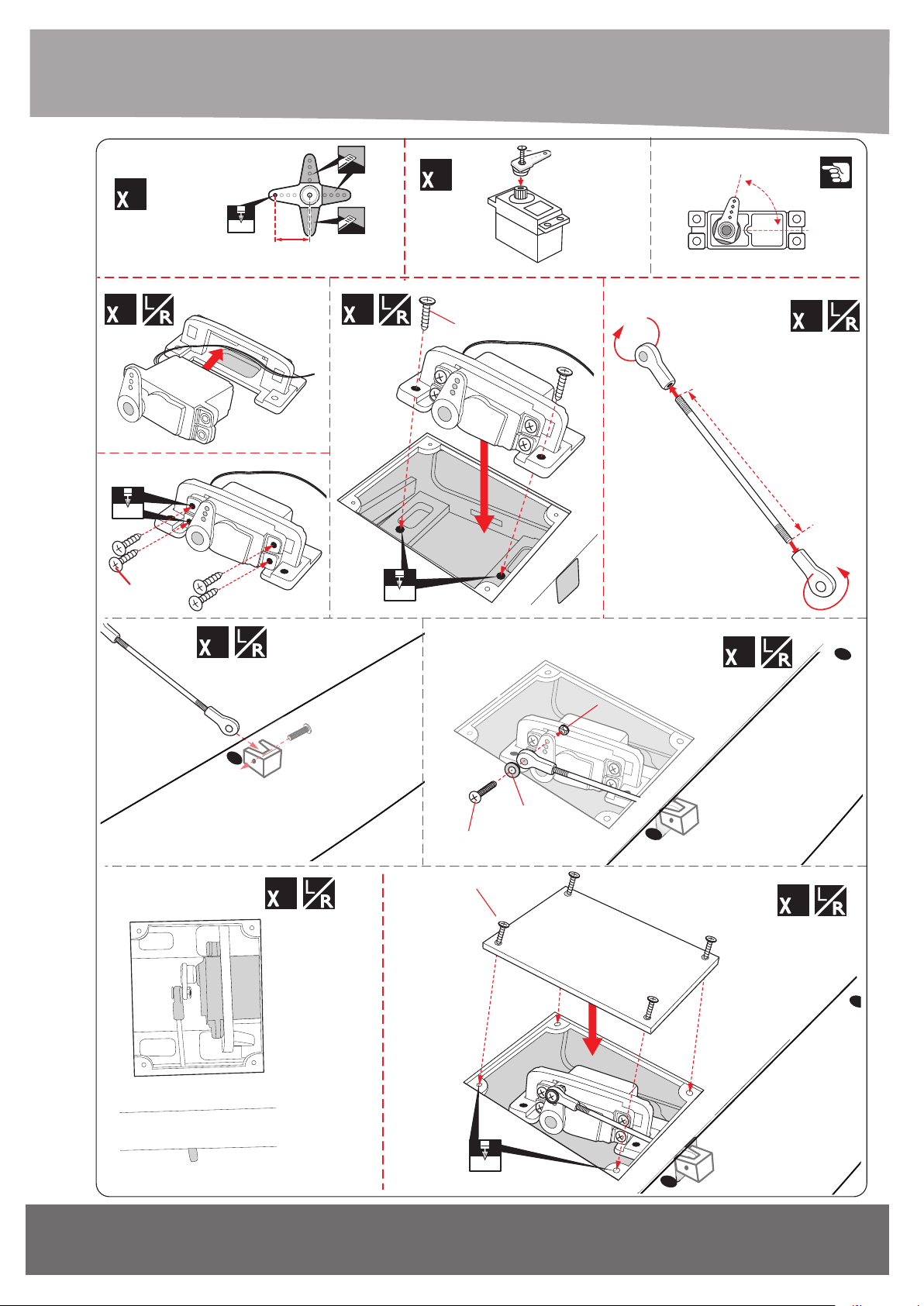
3x12mm Tp Screw
For Flap Servo
3mm Lock nut
3mm Flat Washer
3x12mm Button Head
Cap Screw
2
2 mm
approx.16mm
2
60
O
2
1.5mm
Screw
2
2
2mm
3x12mm Tp Screw
2
2.6x60mm
2
10
2
Flap
2x10mm
Tp Screw
1.5mm
www.extron-modellbau.de
Flap
2
Art.-Nr. / Item-No.
Page 11
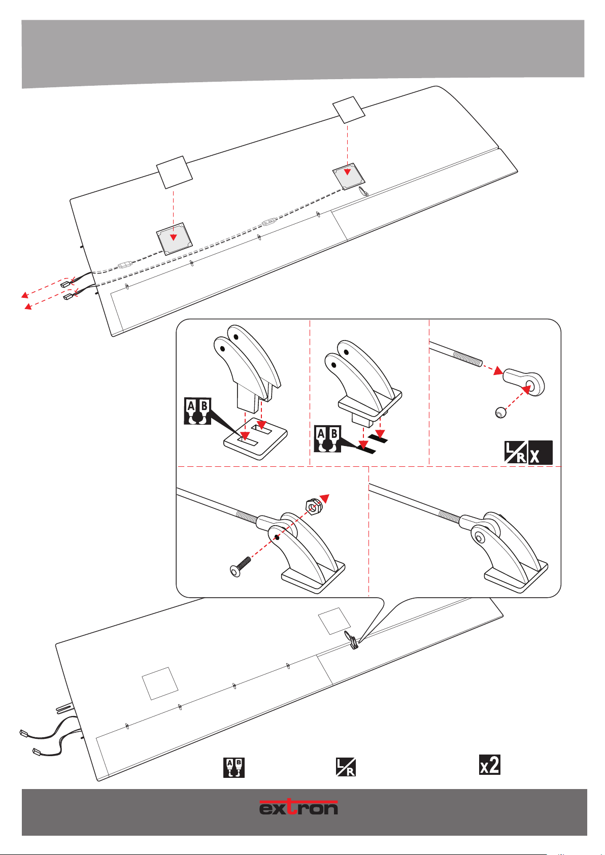
4. MONTAGE / ASSEMBLY
ANSICHT VON UNTEN
BOTTOM VIEW
Push rod
2.6x70mm Push rod
3x12mm
Button Head
Cap Screw
Ball link
Aluminium ball
2
3mm Lock Nut
Horn
Art.-Nr. / Item-No.
Mit Epoxydharz verkleben!
Use Epoxy Glue!
MOD E LL BA U
Eine linke und eine rechte Seite bauen!
Build a left and a right side!
Vorgang x-mal wiederholen.
Repeat this step.
11
Page 12
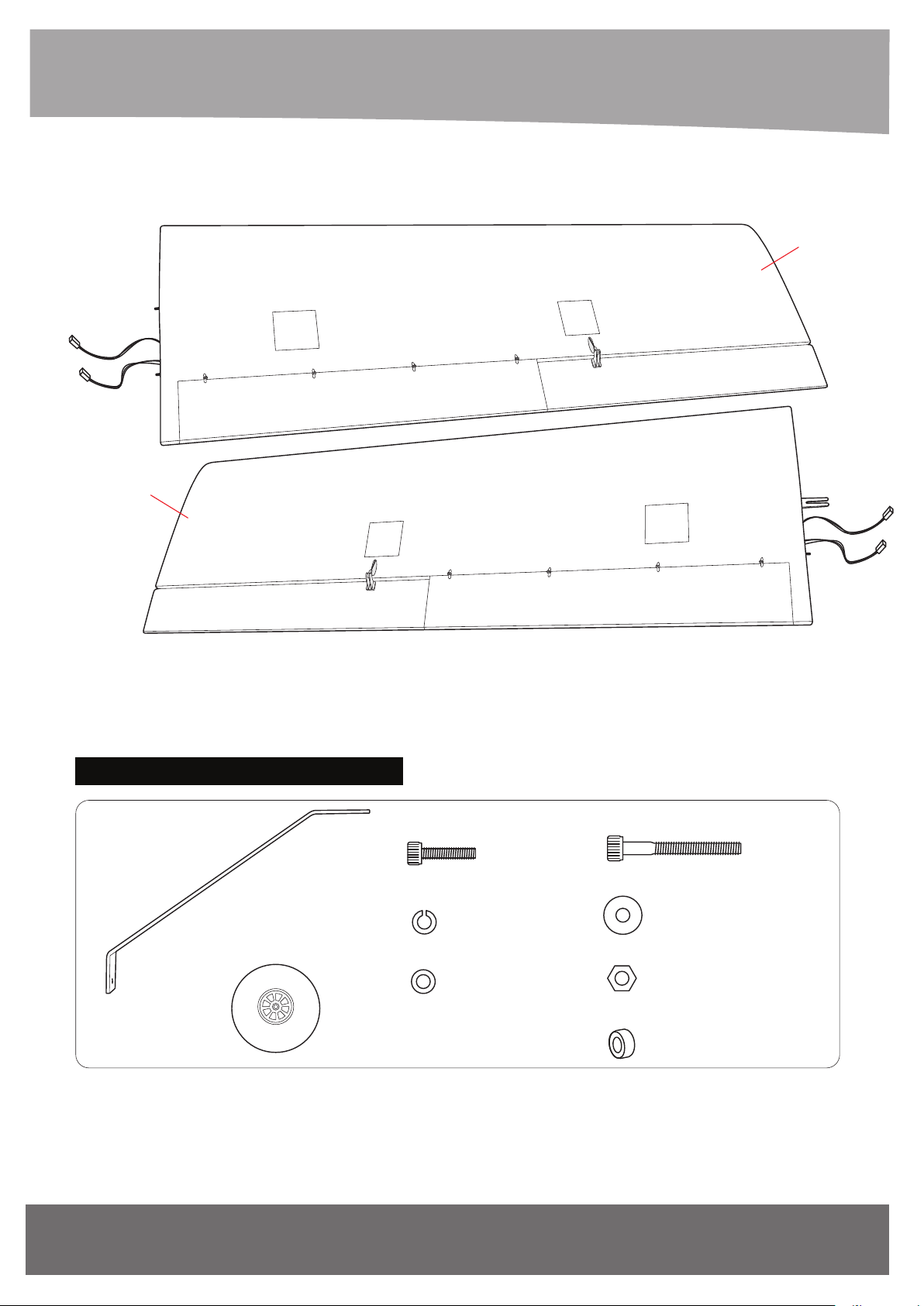
ANSICHT VON UNTEN
BOTTOM VIEW
Right Wing
Left Wing
??? / INSTALLING THE MAIN GEAR
Aluminium main gear 5x20mm Socket Head Cap Screw
- - - 2
115mm Wheel
- - - 2
5mm Spring Washer
5mm Flat Washer
- - - 6
- - - 6
- - - 6
6x55mm Socket Head Cap Screw
- - - 2
6mm Flat Washer
- - - 8
6mm Hex Nut
- - - 4
6mm Plastic Washer
- - - 2
12
www.extron-modellbau.de
Art.-Nr. / Item-No.
Page 13
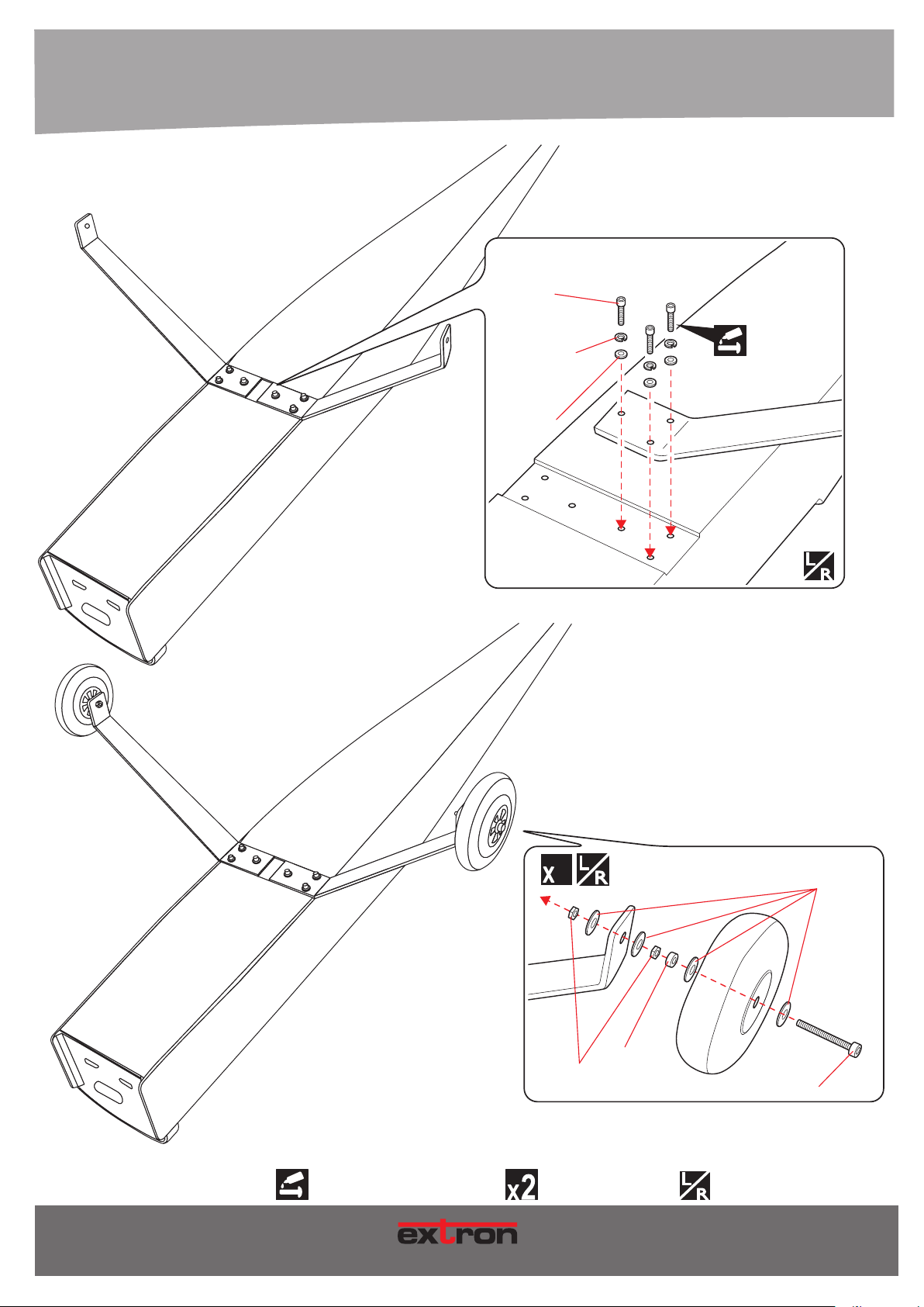
4. MONTAGE / ASSEMBLY
ANSICHT VON UNTEN
BOTTOM VIEW
5x20mm
Socket Head
Cap Screw
5mm
Spring Washer
5mm
Flat Washer
2
2
6mm
Flat Washer
Art.-Nr. / Item-No.
Schraubensicherung verwenden!
Use Screw Cement!
MOD E LL BA U
6mm
Hex Nut
Vorgang x-mal wiederholen.
Repeat this step.
6mm
Plastic Washer
6x55mm
Socket Head
Cap Screw
Eine linke und eine rechte Seite bauen!
Build a left and a right side!
13
Page 14
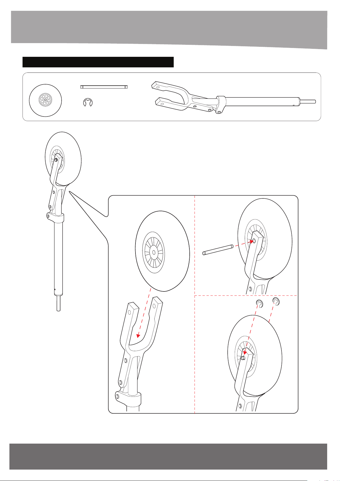
??? / INSTALLING THE NOSE GEAR
100mm Wheel
6x54mm Wheel axle
E - clip
- - - 1
Nose Strut
- - - 1
- - - 2
- - - 1
14
www.extron-modellbau.de
Art.-Nr. / Item-No.
Page 15
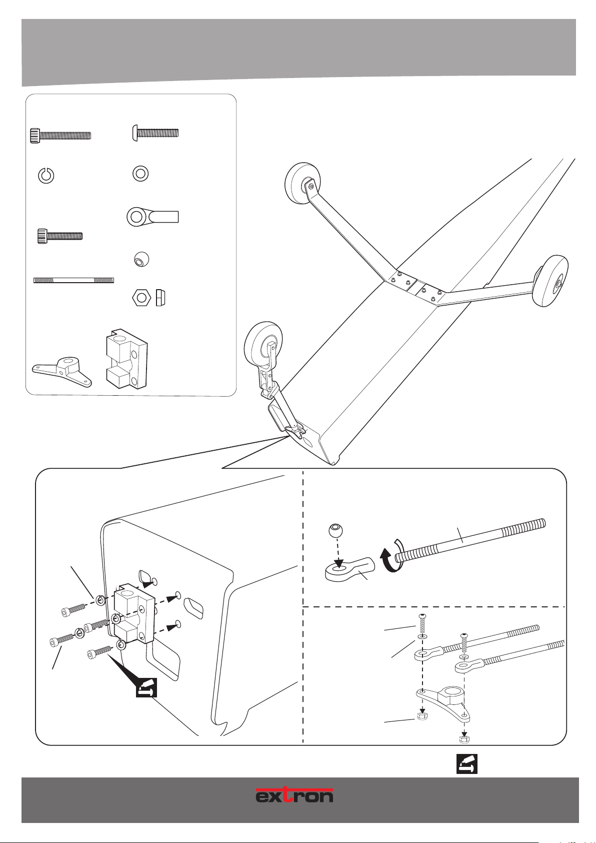
4. MONTAGE / ASSEMBLY
4x20mm
Socket Head Cap Screw
3x12mm
Button Head Cap Screw
- - - 4
4mm Spring Washer
3mm Flat Washer
- - - 4
Ball Link
4x10mm
Socket Head Cap Screw
- - - 1
Aluminium Ball
2.6x177mm
Push rod nose gear
3mm Lock Nut
- - - 2
Aluminium Nose Wheel Steering Arm
and Mount Set
- - - 1
- - - 4
- - - 4
- - - 4
- - - 4
- - - 4
ANSICHT VON UNTEN
BOTTOM VIEW
4mm
Spring Washer
4x20mm
Socket Head Cap Screw
Art.-Nr. / Item-No.
Aluminium Ball
3x12mm
Button Head Cap Screw
3mm Flat Washer
M O DE L L B AU
Push rod
Ball Link
3mm Lock Nut
Schraubensicherung verwenden!
Use Screw Cement!
15
Page 16
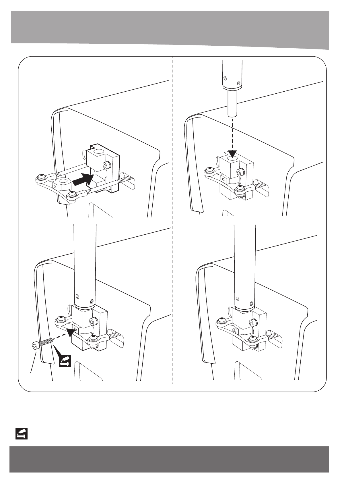
4x10mm
Socket Head Cap Screw
Schraubensicherung verwenden!
Use Screw Cement!
16
www.extron-modellbau.de
Art.-Nr. / Item-No.
Page 17
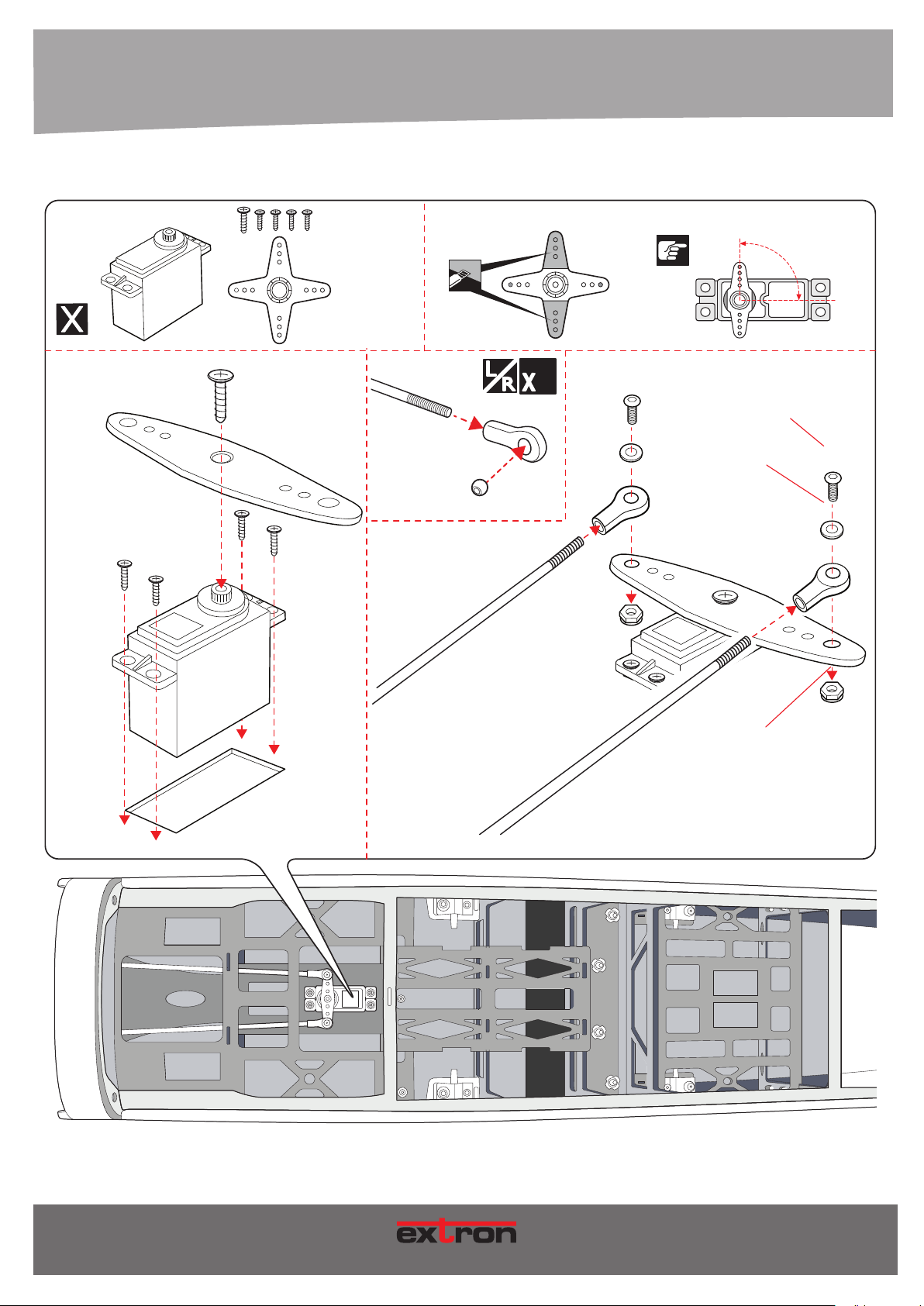
4. MONTAGE / ASSEMBLY
For Nose Gear Servo
90
o
Push rod
Aluminium ball
Ball link
2
3x12mm
Button Head Cap Screw
3mm
Flat Washer
3mm
Lock Nut
Art.-Nr. / Item-No.
17
MODE L LB AU
Page 18
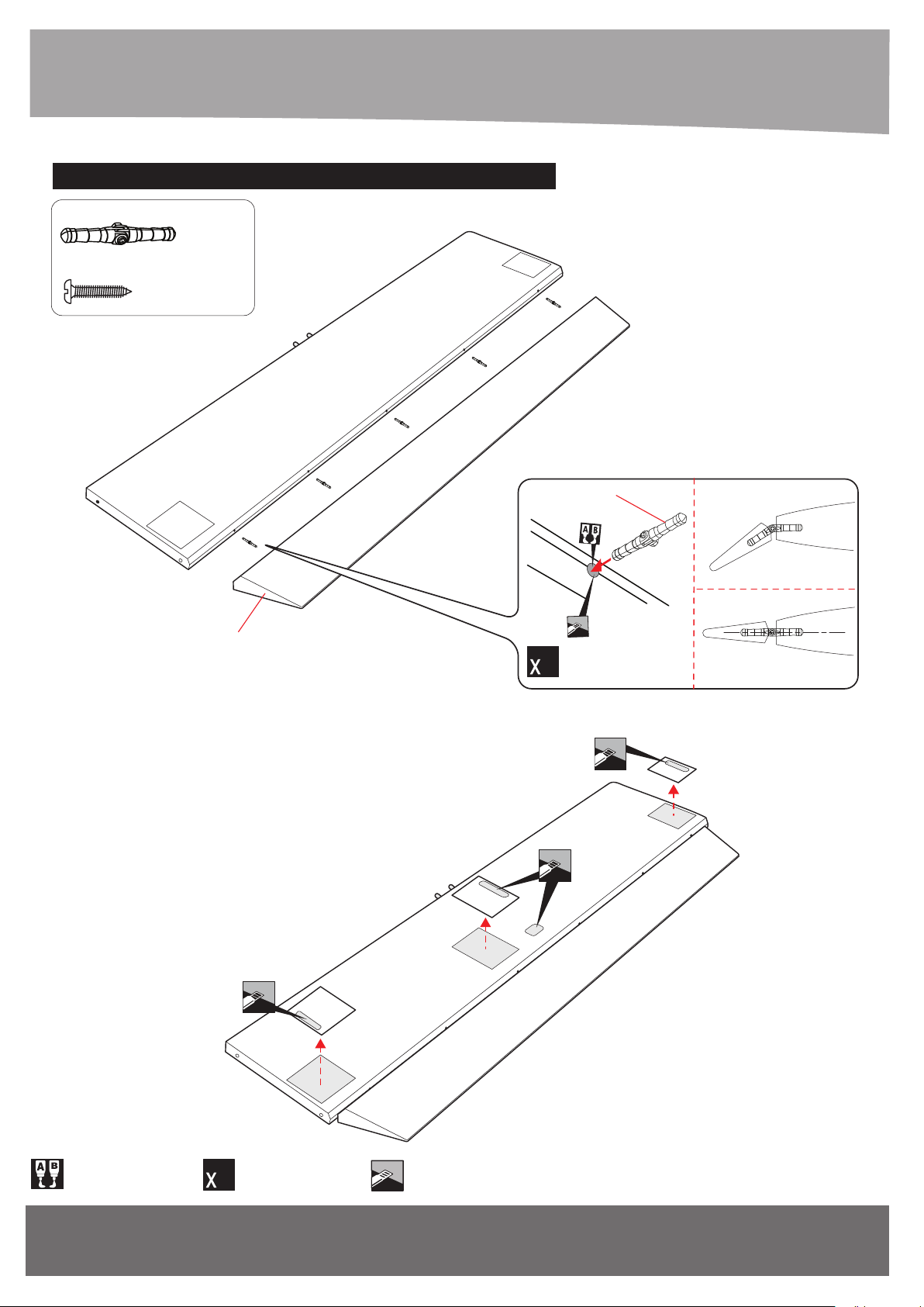
???/ HORIZONTAL & VERTICAL STABILIZER
44mm Pinned Hinge
- - - 5
2x10mm Tp Screw
- - - 12
ANSICHT VON UNTEN
BOTTOM VIEW
44mm
Elevator
???/ HORIZONTAL & VERTICAL STABILIZER SERVOS
5
Mit Epoxydharz verkleben!
Use Epoxy Glue!
18
Vorgang x-mal wiederholen.
6
Repeat this step.
Markierte Fläche abschneiden!
Cut the marked area!
www.extron-modellbau.de
Art.-Nr. / Item-No.
Page 19
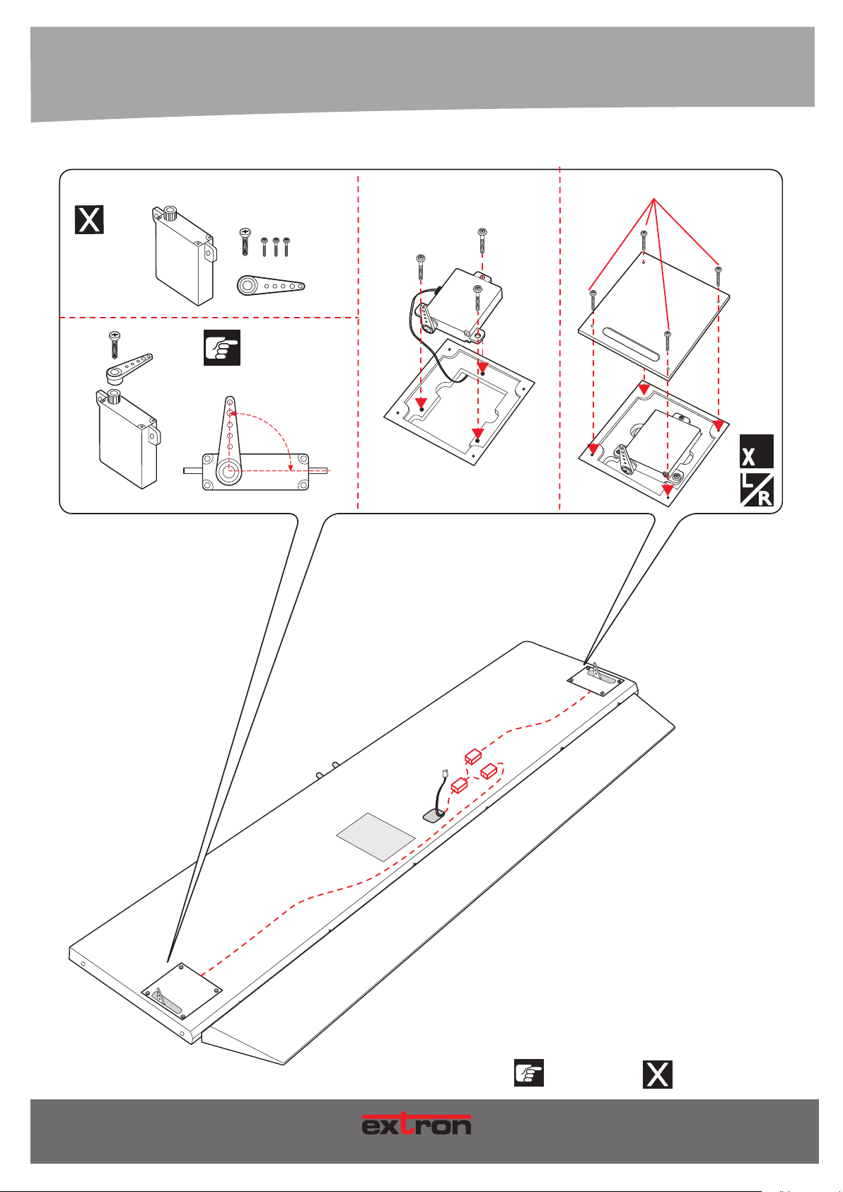
4. MONTAGE / ASSEMBLY
Rudder servo
90
2x10mm TpScrew
o
2
ANSICHT VON UNTEN
BOTTOM VIEW
Vorgang x-mal wiederholen.
Repeat this step.
Genau beachten!
Notice!
Nicht im Lieferumfang enthalten!
Not included!
Art.-Nr. / Item-No.
19
MOD E LL BA U
Page 20
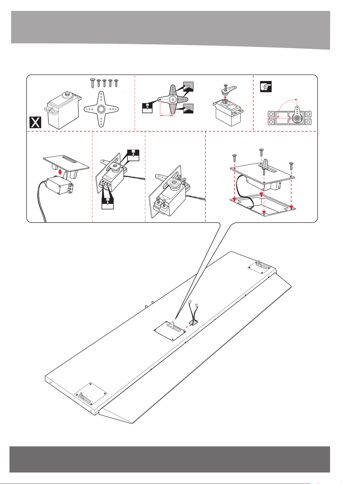
4. MONTAGE / ASSEMBLY
Elevator servo
1.5mm
2mm
approx.16mm
Screw
o
90
2x10mm TpScrew
ANSICHT VON UNTEN
BOTTOM VIEW
1.5mm
20
www.extron-modellbau.de
Art.-Nr. / Item-No.
Page 21
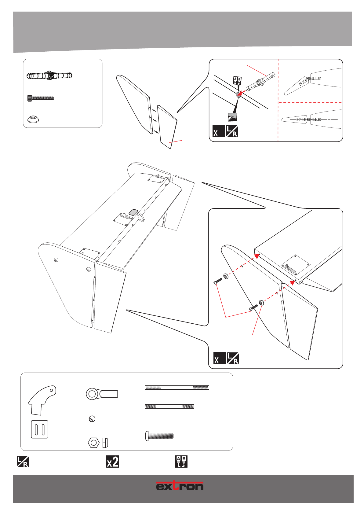
4. MONTAGE / ASSEMBLY
44mm Pinned Hinge
- - - 6
4x25mm Socket Head Cap Screw
- - - 4
4mm aluminum Washer
- - - 4
ANSICHT VON UNTEN
BOTTOM VIEW
44mm
6
Rudder
Horn
- - - 6
- - - 3
Eine linke und eine rechte Seite bauen!
Build a left and a right side!
Ball Link
Aluminium Ball
3mm Lock Nut
Art.-Nr. / Item-No.
2.6x40mm Push rod Rudder
- - - 6
2.6x mm Push rod Elevator
- - - 4
3x12mm Button Head Cap Screw
- - - 6
Vorgang x-mal wiederholen.
Repeat this step.
4x25 Plastic Screw
4mm aluminum Washer
4
- - - 2
- - - 1
- - - 6
Mit Epoxydharz verkleben!
Use Epoxy Glue!
21
M O DE L L B AU
Page 22
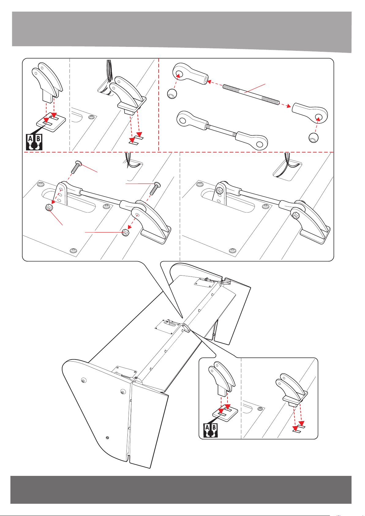
3mm
Lock Nut
2.6x mm Push Rod
3x12mm
Button Head
Cap Screw
ANSICHT VON UNTEN
BOTTOM VIEW
22
www.extron-modellbau.de
Art.-Nr. / Item-No.
Page 23
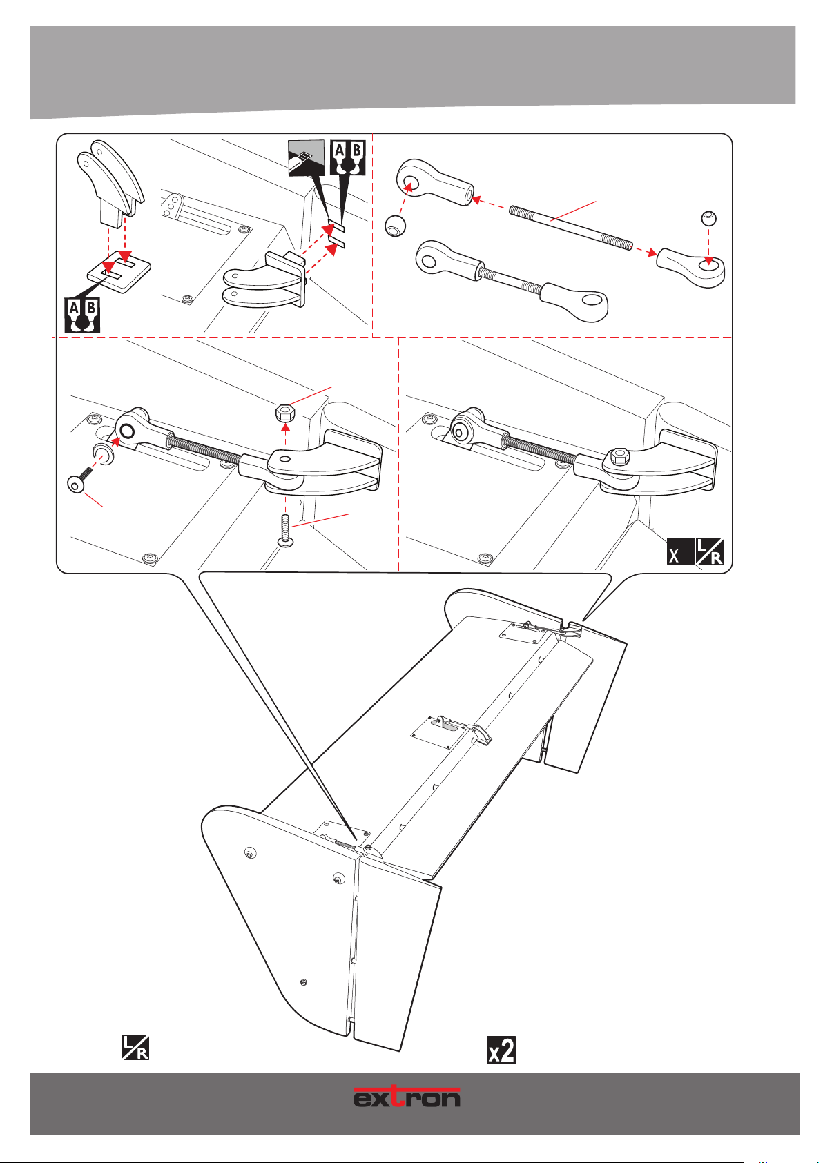
3x12mm
Button Head
Cap Screw
2.6x40mm Push Rod
3mm
Lock Nut
3mm
Lock Nut
2
Eine linke und eine rechte Seite bauen!
Build a left and a right side!
Art.-Nr. / Item-No.
MOD E LL BA U
Vorgang x-mal wiederholen.
Repeat this step.
Mit Epoxydharz verkleben!
Use Epoxy Glue!
23
Page 24
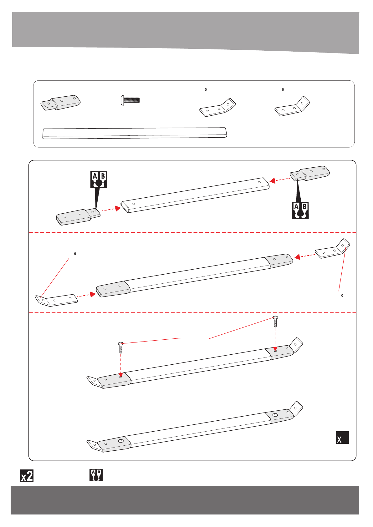
???/ HORIZONTAL & VERTICAL STABILIZER STRUTS
Plastic Strut Attachment
- - - 4
132mm Aluminium Strut
42
3x6mm Button Head Cap Screw
- - - 4
42
Aluminium Strut Attachment 57 Aluminium Strut Attachment
- - - 2
- - - 2
- - - 2
Vorgang x-mal wiederholen.
Repeat this step.
57
3x6mm
Button Head
Cap Screw
2
Mit Epoxydharz verkleben!
Use Epoxy Glue!
24
www.extron-modellbau.de
Art.-Nr. / Item-No.
Page 25
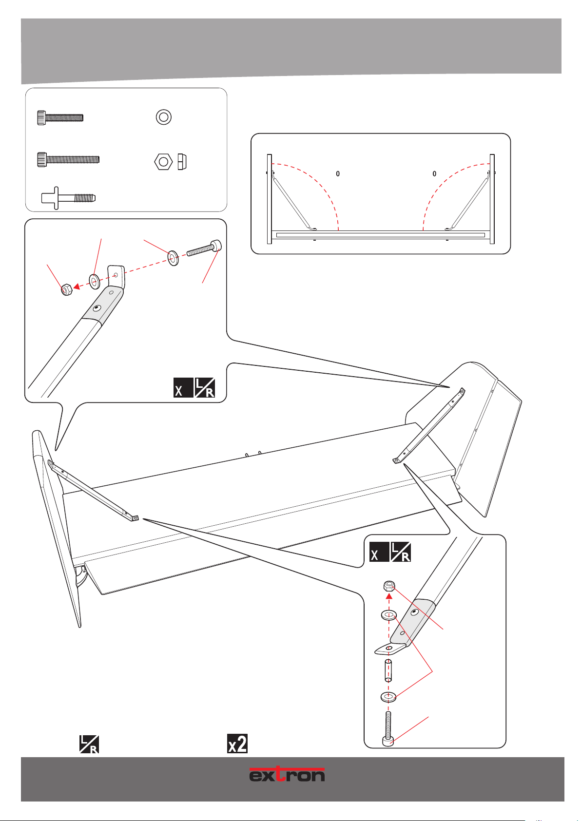
4. MONTAGE / ASSEMBLY
3x20mm Socket Head Cap Screw
- - - 2
3x35mm Socket Head Cap Screw
- - - 2
6x45mm Plastic Screw
- - - 2
LEFT RIGHT
3mm
Lock Nut
3mm
Flat Washer
3mm Flat Washer
- - - 8
3mm Lock Nut
- - - 4
3x35mm
Socket Head
Cap Screw
Horizontal & Vertical Stabilizer Side View
90 90
DRAUFSICHT
TOP VIEW
2
TOP
2
3mm
Lock Nut
3mm
Flat Washer
Eine linke und eine rechte Seite bauen!
Build a left and a right side!
Art.-Nr. / Item-No.
Vorgang x-mal wiederholen.
Repeat this step.
M O DE L L B AU
3x20mm
Socket Head
Cap Screw
BOTTOM
25
Page 26
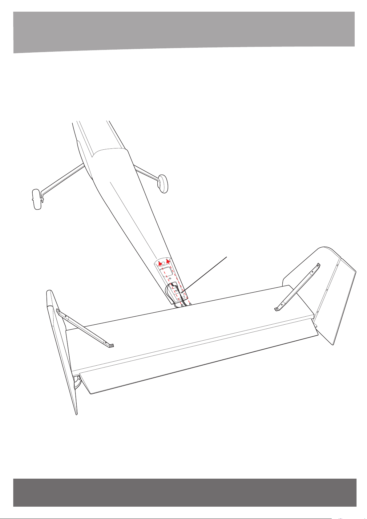
DRAUFSICHT
TOP VIEW
Servo extension leads rudder
26
www.extron-modellbau.de
Art.-Nr. / Item-N
Page 27
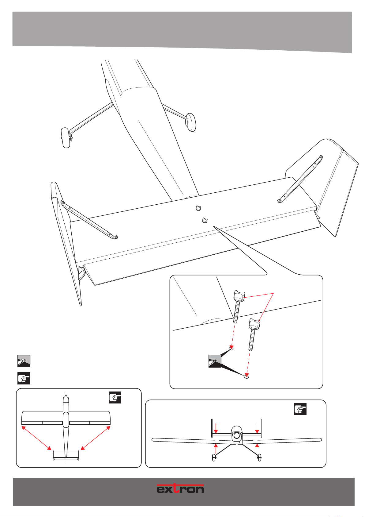
DRAUFSICHT
TOP VIEW
Markierte Fläche abschneiden!
Cut the marked area!
Genau beachten!
Notice!
A A’
6x45mm Plastic Screw
A=A’
B=B’
B B’
Art.-Nr. / Item-No.
27
M O DE L L B AU
Page 28
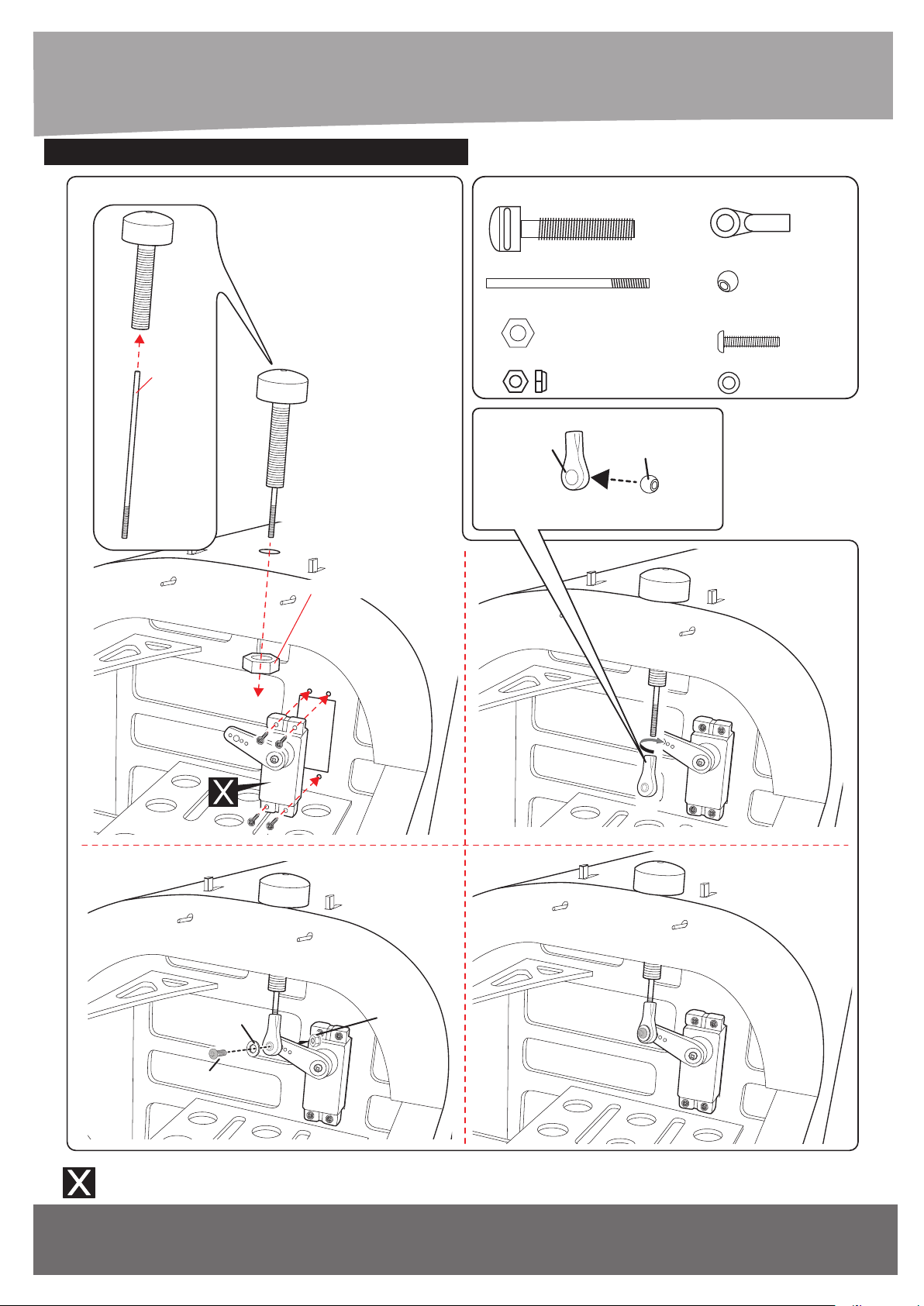
4. MONTAGE / ASSEMBLY
???/ INSTALLING THE TOW SERVO
2.6x80mm
Push Rod
8mm Hex Nut
Tow Screw
- - - 1
2.6x80mm Push rod
- - - 1
8mm Hex Nut
- - - 1
3mm Lock Nut
- - - 1
Ball Link Aluminium Ball
Ball Link
- - - 1
Aluminium Ball
- - - 1
3x12mm
Button Head Cap Screw
- - - 1
3mm Flat Washer
- - - 1
3mm Flat Washer
3x12mm
Button Head Cap Screw
Nicht im Lieferumfang enthalten!
Not included!
28
3mm Lock Nut
www.extron-modellbau.de
Art.-Nr. / Item-No.
Page 29
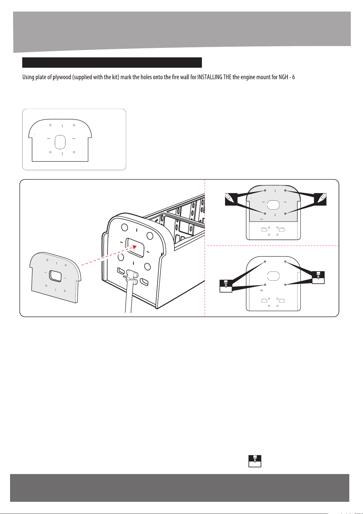
???/ INSTALLING THE ENGINE MOUNT
May be you also need to trim some wood from the tri-angle wood for the installation.
Plate of plywood engine
NGH - 65CC
- - - 1
5CC or motor..............
NGH - 65CC
NGH - 65CC
NGH - 65CC
6.2mm
6.2mm
Art.-Nr. / Item-No.
www.extron-modellbau.de
Loch bohren mit dem dargestellten Durchmesser.
6.2mm
Drill a hole with the shown diameter
29
Page 30
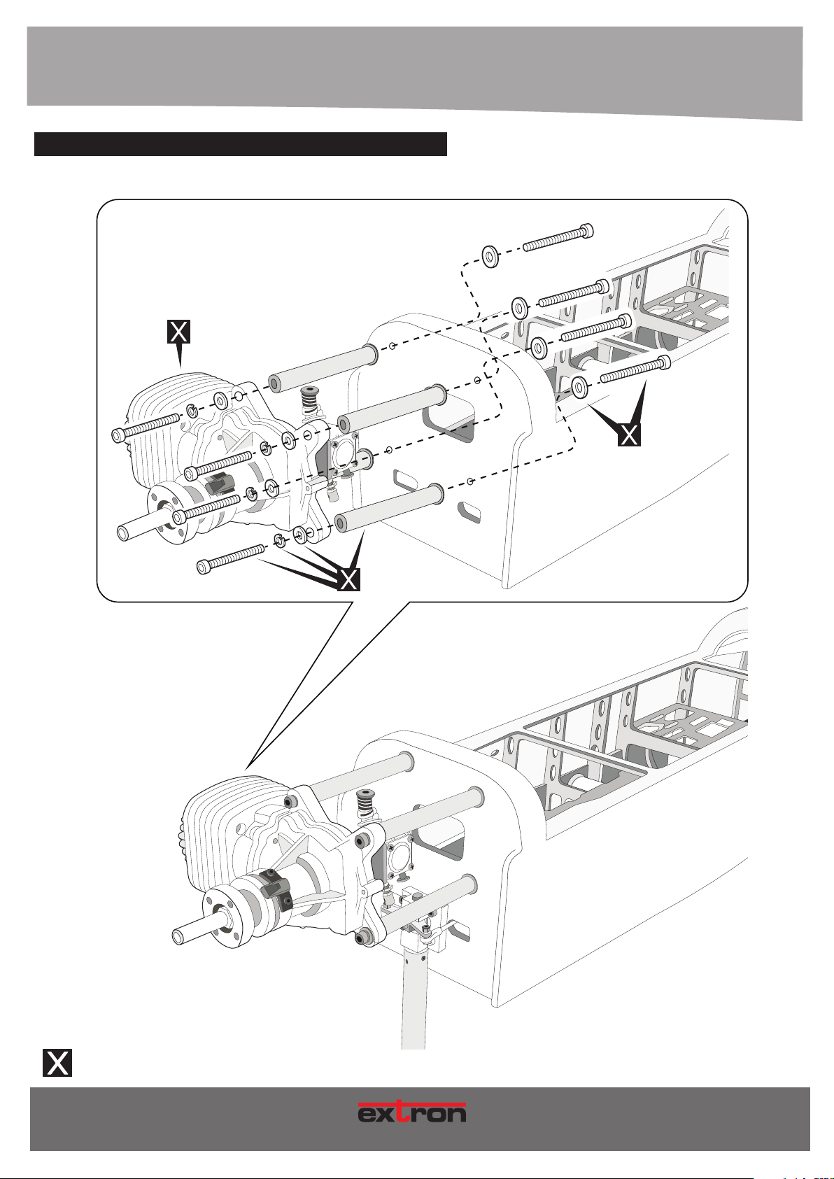
4. MONTAGE / ASSEMBLY
???/ INSTALLING THE ENGINE (If use MOTOR see in page 45)
Nicht im Lieferumfang enthalten!
Not included!
30
Art.-Nr. / Item-N
M O DE L L B AU
Page 31
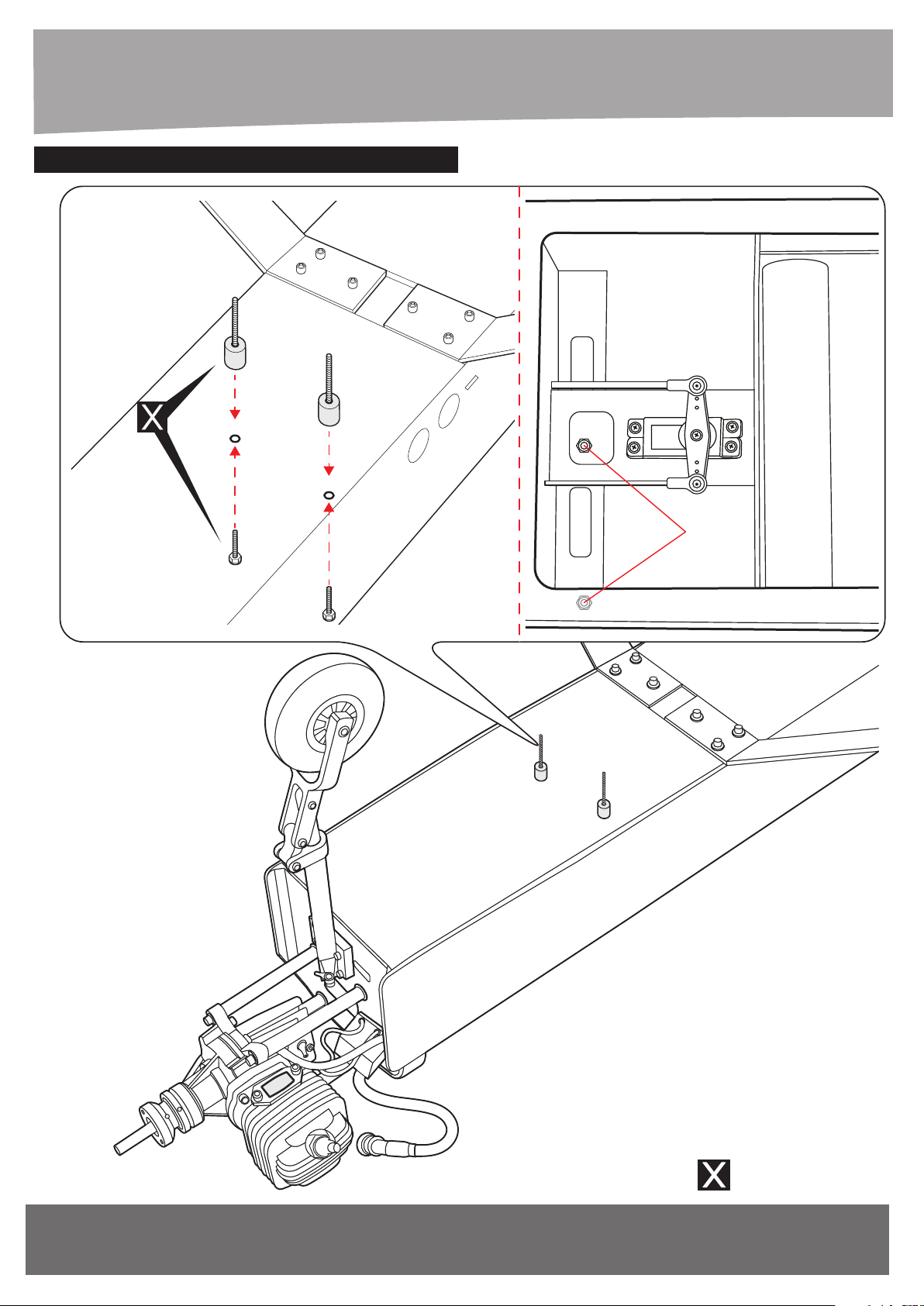
???/ INSTALLING THE EXHAUST PIPE
Screw
ANSICHT VON UNTEN
BOTTOM VIEW
Art.-Nr. / Item-No.
www.extron-modellbau.de
Nicht im Lieferumfang enthalten!
Not included!
31
Page 32
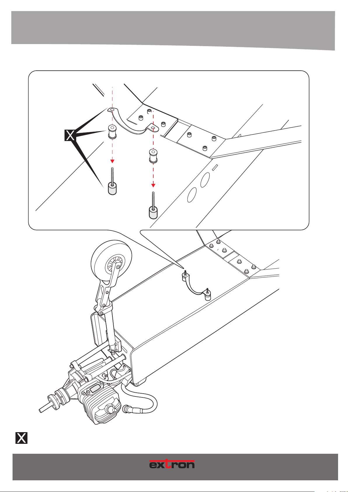
4. MONTAGE / ASSEMBLY
ANSICHT VON UNTEN
BOTTOM VIEW
Nicht im Lieferumfang enthalten!
Not included!
32
Art.-Nr. / Item-No.
M O DE L L B AU
Page 33
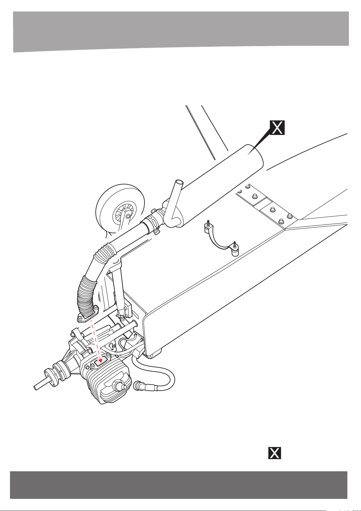
ANSICHT VON UNTEN
BOTTOM VIEW
Art.-Nr. / Item-No.
www.extron-modellbau.de
Nicht im Lieferumfang enthalten!
Not included!
33
Page 34
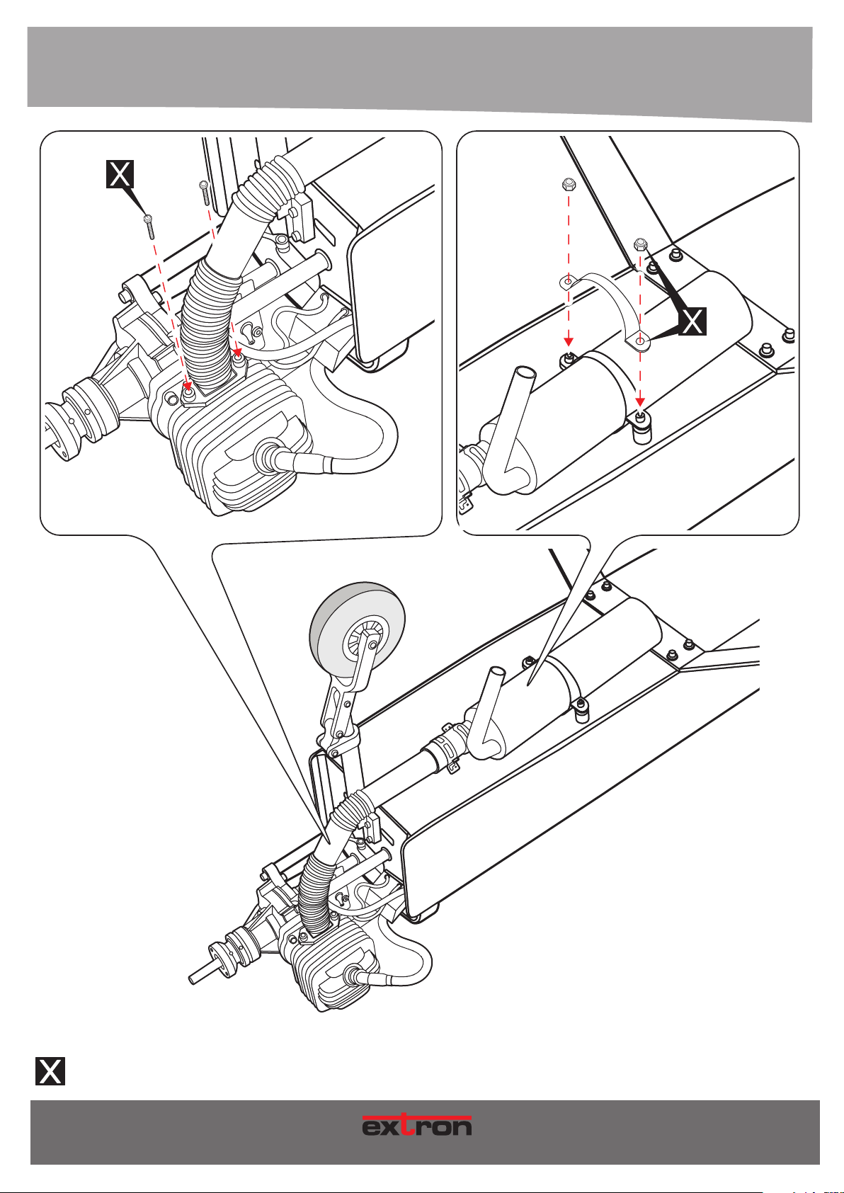
4. MONTAGE / ASSEMBLY
ANSICHT VON UNTEN
BOTTOM VIEW
Nicht im Lieferumfang enthalten!
Not included!
34
Art.-Nr. / Item-No.
M O DE L L B AU
Page 35
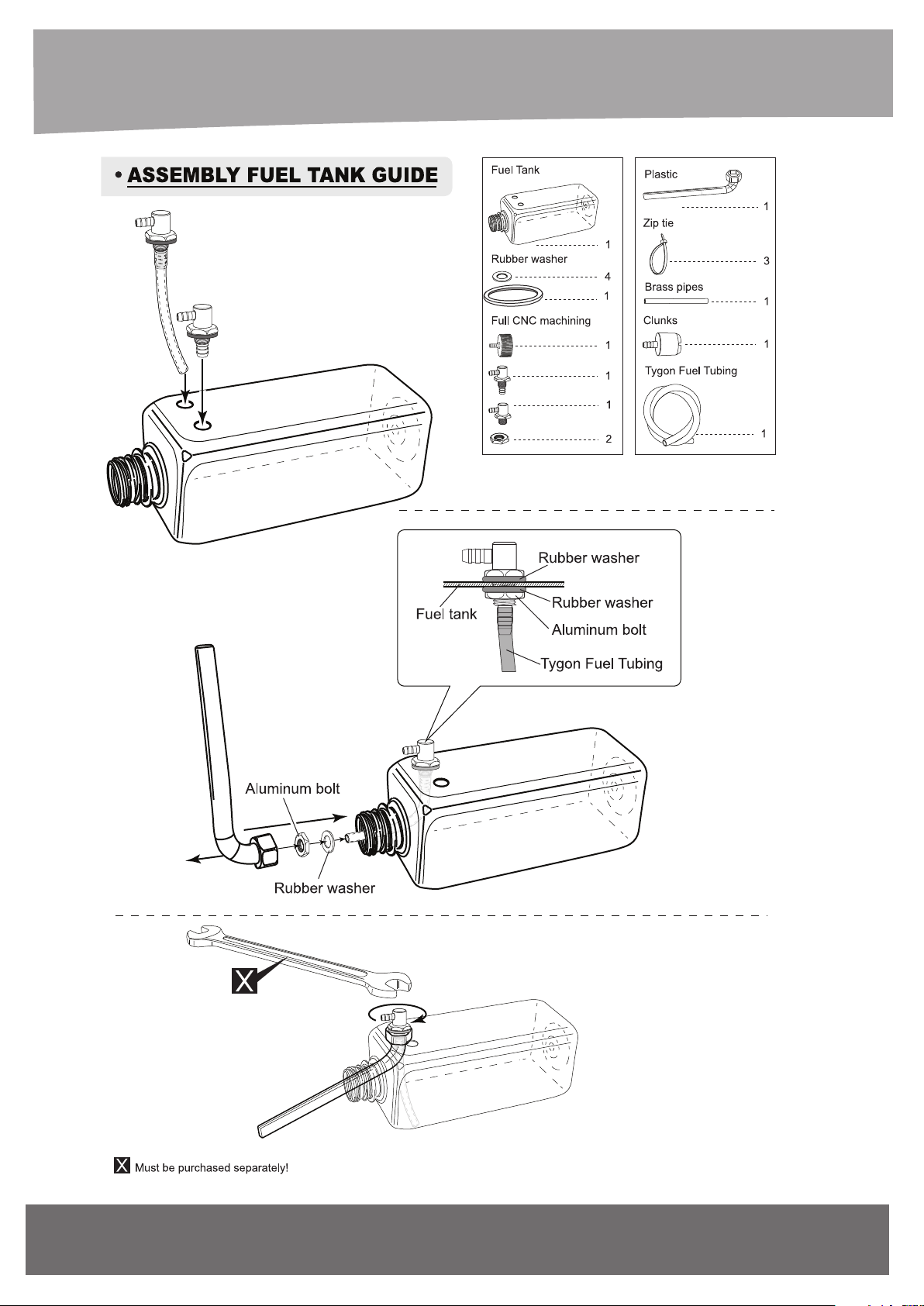
700cc
Art.-Nr. / Item-No.
www.extron-modellbau.de
35
Page 36
36
Art.-Nr. / Item-No.
M O DE L L B AU
Page 37
4. MONTAGE / ASSEMBLY
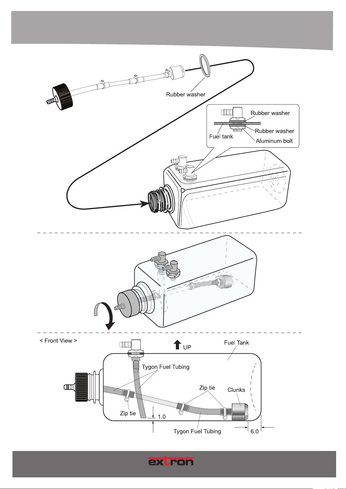
1) The stopper has been pre-assembled at the
factory.
2) Using a modeling knife, cut one length of silicon
fuel line (the length of silicon fuel line is calculated by
how the weighted clunk should rest about 8mm away
from the rear of the tank and move freely inside the
tank). Connect one end of the line to the weighted
clunk and the other end to the nylon pick up tube in
the stopper.
3) Carefully bend the second nylon tube up at a 45
degree angle (using a cigarette lighter). This tube will
be the vent tube to the muffler.
4) Carefully bend the third nylon tube down at a 45
degree angle (using a cigarette lighter). This tube
will be vent tube to the fueling valve.
When the stopper assembly is installed in the
tank, the top of the vent tube should rest just below
the top surface of the tank. It should not touch the top
of the tank.
Do not secure the tank into place permanently
until after balancing the airplane. You may need to
remove the tank to mount the battery in the fuel tank
compartment.
5) Test fit the stopper assembly into the tank. It may
be necessary to remove some of the flashing around
the tank opening using a modeling knife. If flashing is
present, make sure none of it falls into the tank.
6) When satisfied with the alignment of the stopper
assembly tighten the 3mm x 20mm machine screw
until the rubber stopper expands and seals the tank
opening. Do not over tighten the assembly as this
could cause the tank to split.
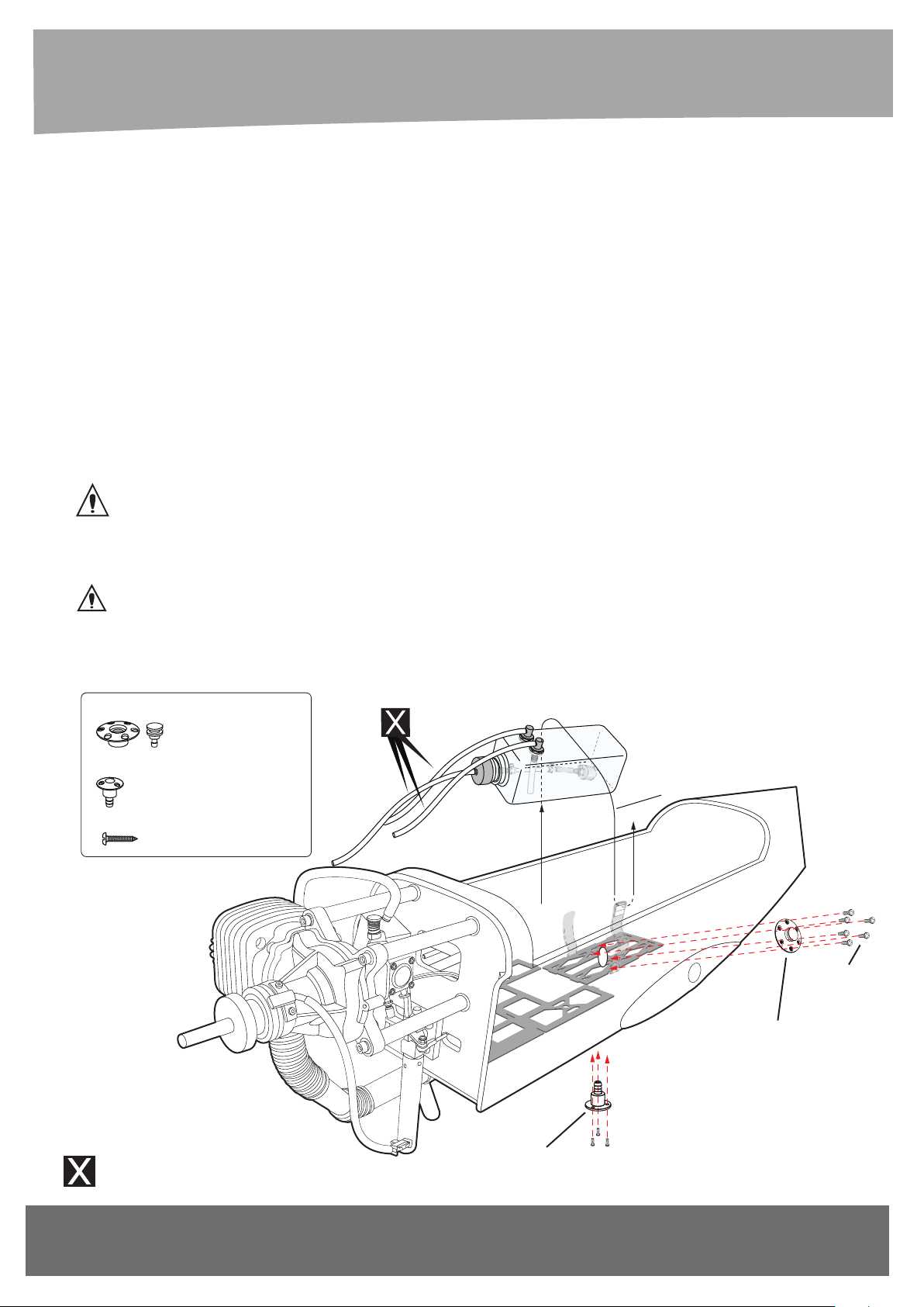
7) Using a modeling knife, cut 3 lengths of fuel line.
Connect 2 lines to the 2 vent tubes and 1 line to the
fuel pickup tube in the stopper.
8) Feed three lines through the fuel tank
compartment and through the pre-drilled hole in the
firewall. Pull the lines out from behind the engine,
while guiding the fuel tank into place. Push the fuel
tank as far forward as possible, the front of the tank
should just about touch the back of the firewall.
Blow through one of the lines to ensure the fuel lines
have not become kinked inside the fuel tank
compartment. Air should flow through easily.
9. Secure the fuel tank.
Magnetic Anodized Fuel Dot
- - - - - 1
Alu. Anodized Fuel Vent Line Plug
- - - - - 1
2x5mm Tp Screw
- - - 9
Velcro
2x5mm Tp Screw
Fuel Dot
Must be purchased
separately!
Art.-Nr. / Item-No.
Tank Vent
www.extron-modellbau.de
37
Page 38
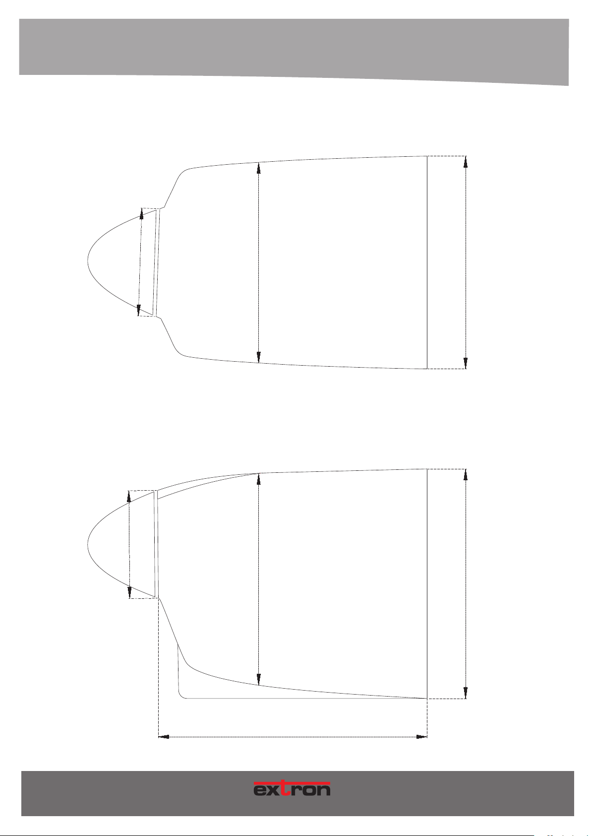
87mm
87mm
COWLING DIMENSIONAL DETAIL
162mm
W
172mm
38
171mm
232mm
M O D E L L B A U
H
186mm
Art.-Nr. / Item-No.
Page 39
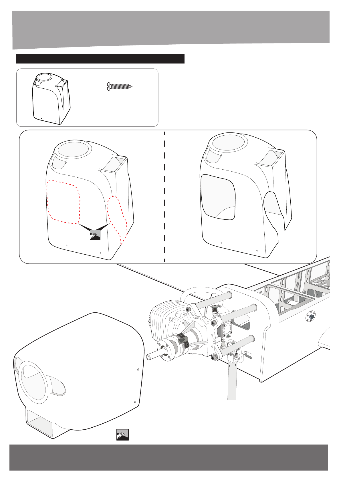
???/ INSTALLING THE COWLING
3x12mm Tp Screw Cowling
- - - 1
- - - 4
Art.-Nr. / Item-No.
Markierte Fläche abschneiden!
Cut the marked area!
www.extron-modellbau.de
39
Page 40
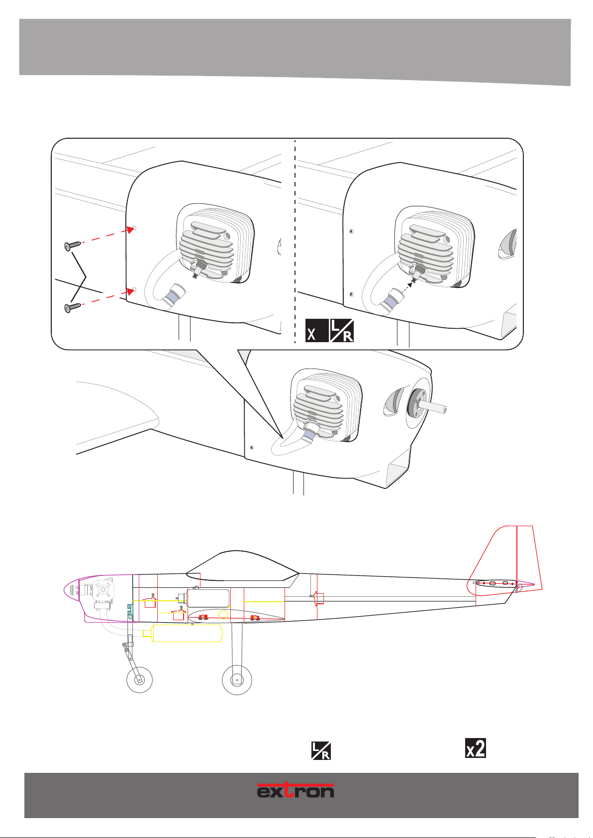
4. MONTAGE / ASSEMBLY
3x12mm
Tp Screw
2
40
MOD E L L B A U
Eine linke und eine rechte Seite bauen!
Build a left and a right side!
Vorgang x-mal wiederholen.
Repeat this step.
Art.-Nr. / Item-No.
Page 41
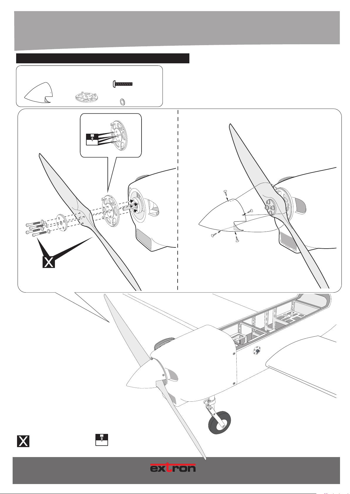
???/ INSTALLING THE PROPELLER
3x8mm
Spinner Cap
Back Plate
5.1mm
Button Head Cap Screw
3mm Flat Washer
- - - 1- - - 1
- - - 4
- - - 4
Nicht im Lieferumfang enthalten!
Not included!
Loch bohren mit dem dargestellten Durchmesser.
5.1mm
Drill a hole with the shown diameter
M O D E L L B A U
Art.-Nr. / Item-No.
41
Page 42
4. MONTAGE / ASSEMBLY
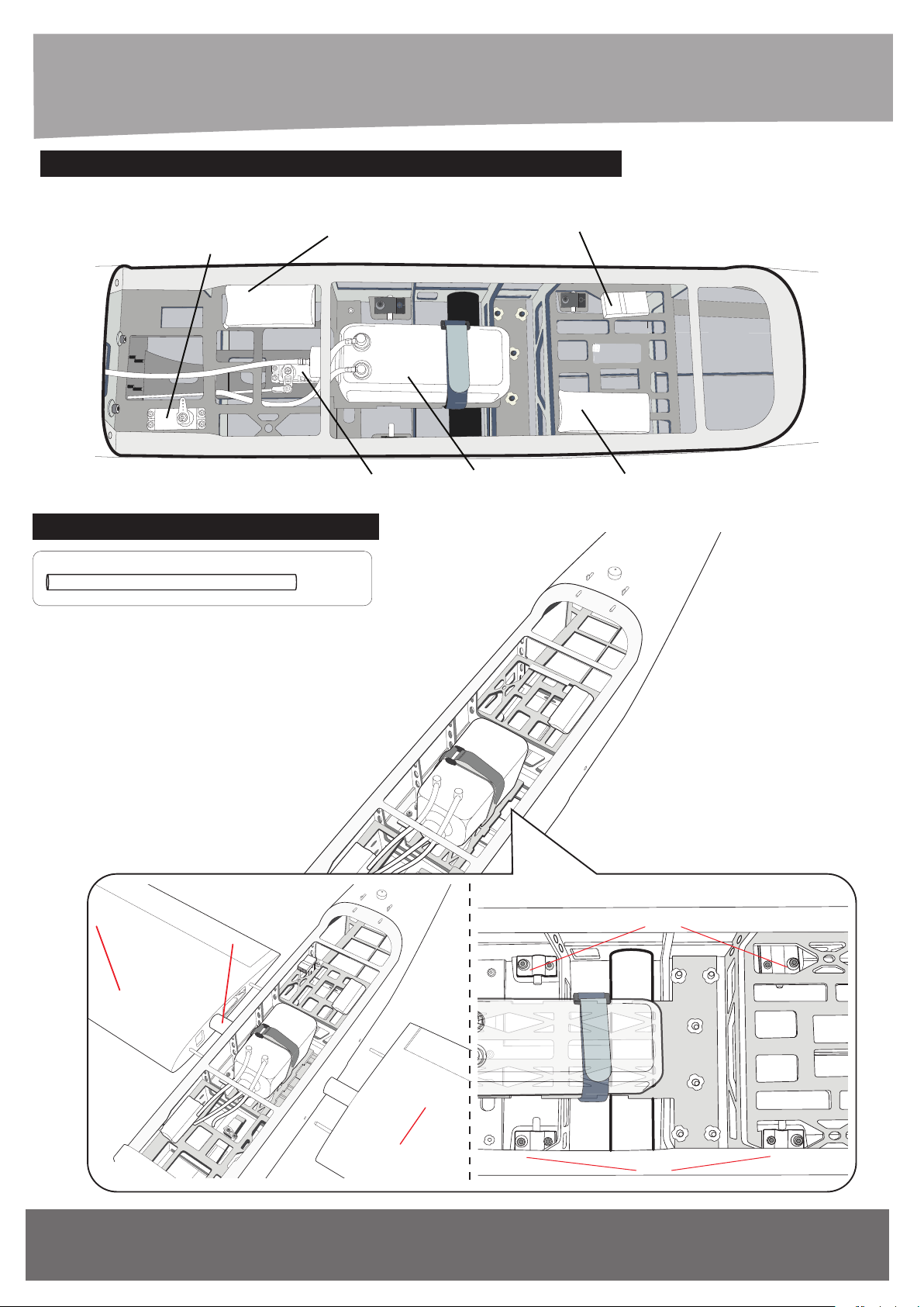
???/ INSTALLING THE THE SWITCH, RECEIVER AND BATTERY
DRAUFSICHT
TOP VIEW
Battery engine
Servo gas
Receiver
Servo nose gear
???/ INSTALLING THE MAIN WING
Ø32 - 832mm Aluminium Tube
- - - 1
832mm Aluminium Tube
Fuel tank
Battery receiver
Screw
42
Right Wing
Left Wing
Screw
www.extron-modellbau.de
Page 43
4. MONTAGE / ASSEMBLY
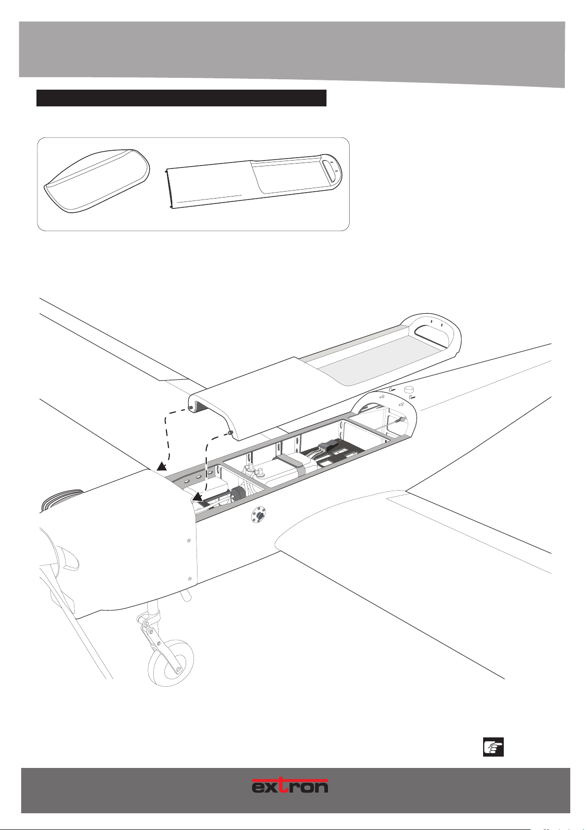
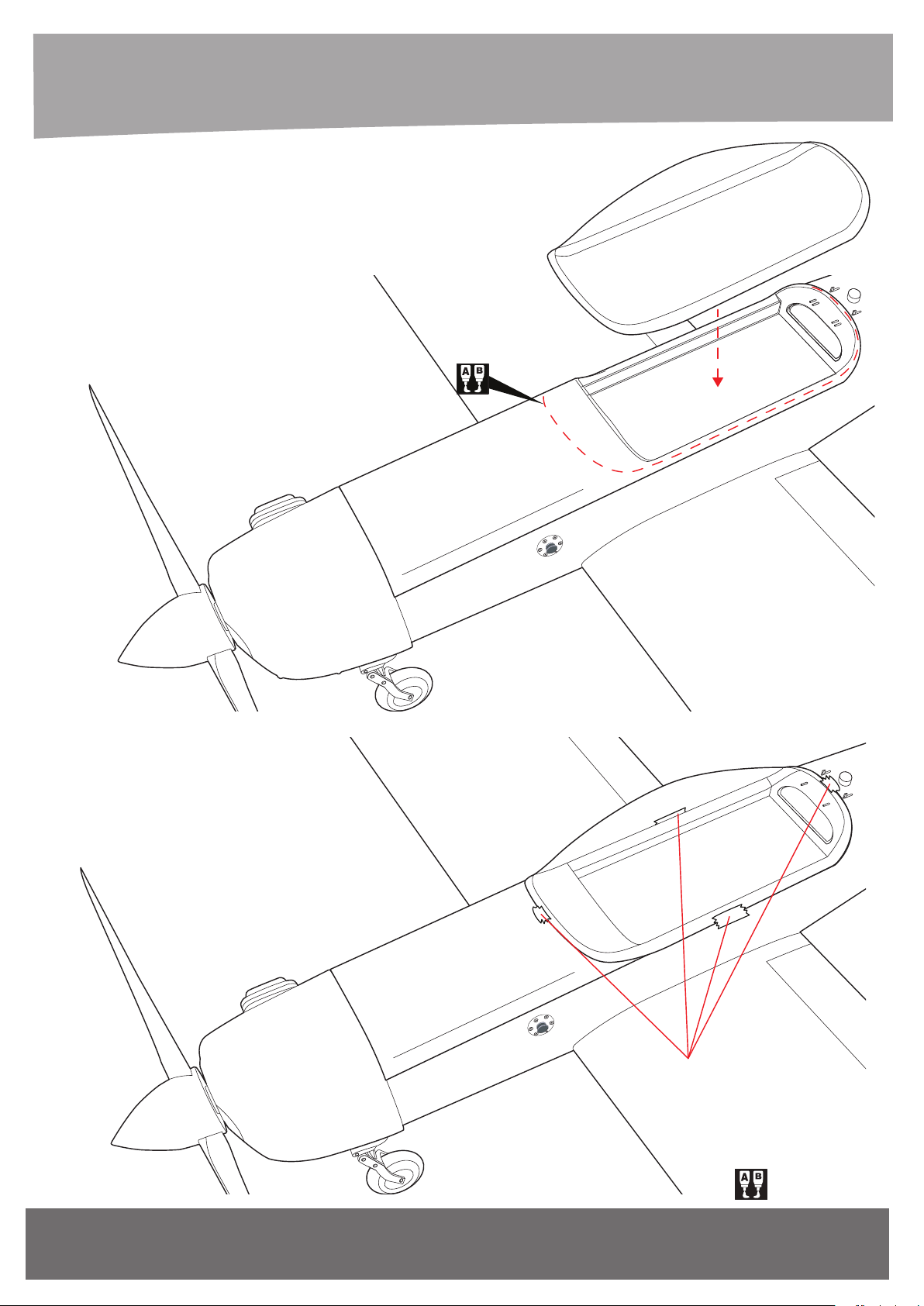
???/ INSTALLING THE CANOPY
Canopy Hatch
- - - 1
Position the canopy so the rear frame on the canopy is aligned
with the rear edge of the cockpit opening. Use canopy glue to
secure the canopy to the canopy hatch. Use low-tack tape to
hold the canopy in position until the glue fully cures. Wrap the
tape completely around the canopy hatch.
- - - 1
Art.-Nr. / Item-No.
Genau beachten!
Notice!
43
M O D E L L B A U
Page 44
4. MONTAGE / ASSEMBLY
DRAUFSICHT
TOP VIEW
44
www.extron-modellbau.de
Adhesive tape
Mit Epoxydharz verkleben!
Art.-Nr. / Item-N
Page 45
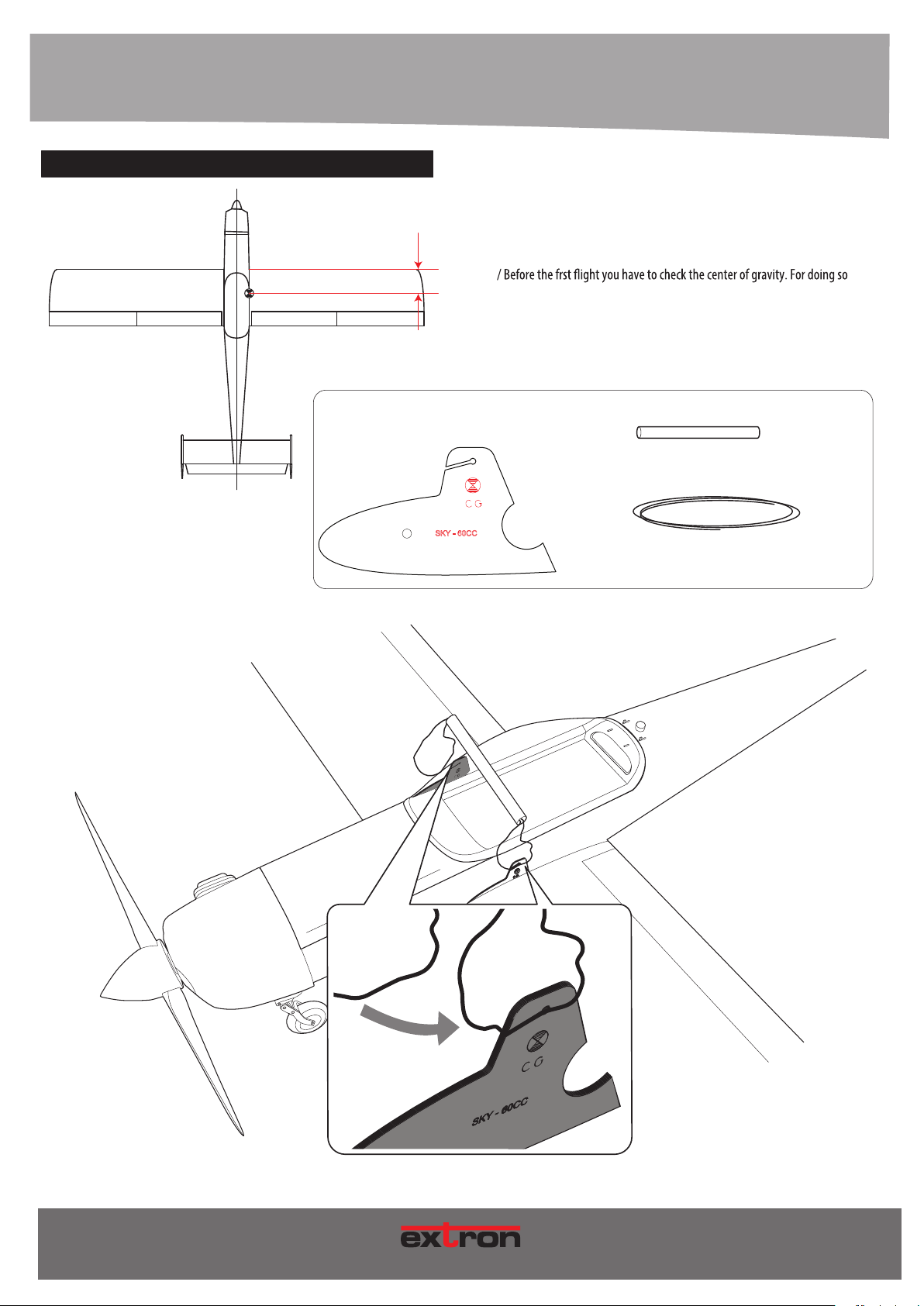
SCHWERPUNKT / CENTER OF GRAVITY
CG
101mm
Abschließend muss der Schwerpunkt am Modell überprüft werden. Dazu
werden alle Komponenten (auch der Akku!) im Modell montiert. Der
Schwerpunkt liegt exakt 101mm hinter der Naenleiste. Unterstützen
Sie das Modell mit zwei Fingern exakt an diesen Punkten und
beobachten Sie, wie das Modell auspendelt. Die Nase des Modells muss
sich leicht nach unten neigen. Dann ist der Schwerpunkt optimal justiert.
you have to mount all components (also the battery!) in to the model. The
CG is placed 101mm behind the nose cone of the main wing.
Support the model exactly at the marked spots on the bottom side of the
wing. Put the model on two fngers and watch the fuselage. The nose
should point slightly to the ground. Then the CG is placed correctly!
Plate of plywood
Ø 12x100mm Aluminium Tube
- - - 1
2000mm Wire
- - - 1
- - - 2
Art.-Nr. / Item-No.
45
MOD E L L B A U
Page 46
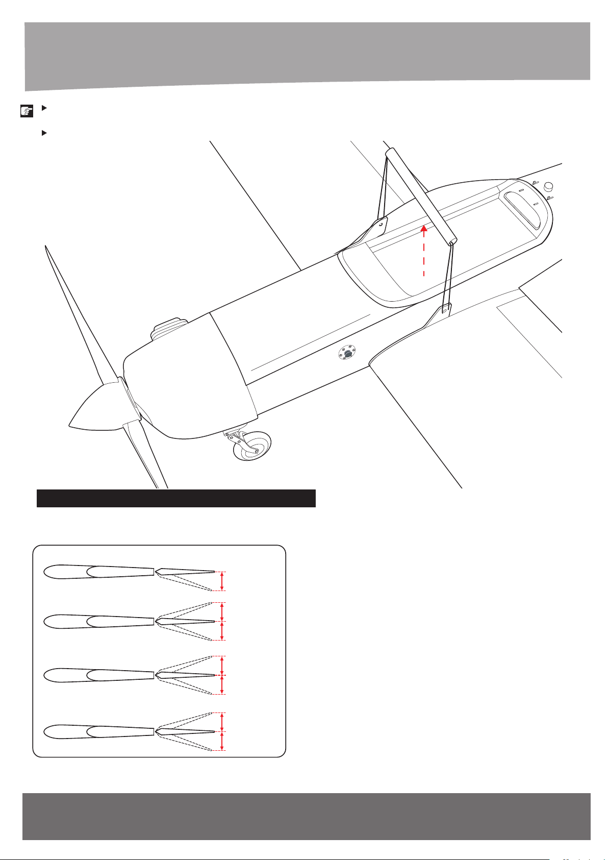
In order to obtain the CG specified, reposition
the receiver and other equipment.
If not obtain the CG specified, add a weight and
adjust.
RUDERAUSSCHLÄGE / CONTROL THROWS
Flap control
Aileron control
Elevator Control
Rudder control
?
?
?
?
?
?
?
mm ...............
mm ...............
mm ...............
mm ...............
mm ...............
mm ...............
mm ...............
46
www.extron-modellbau.de
Art.-Nr. / Item-N
Page 47
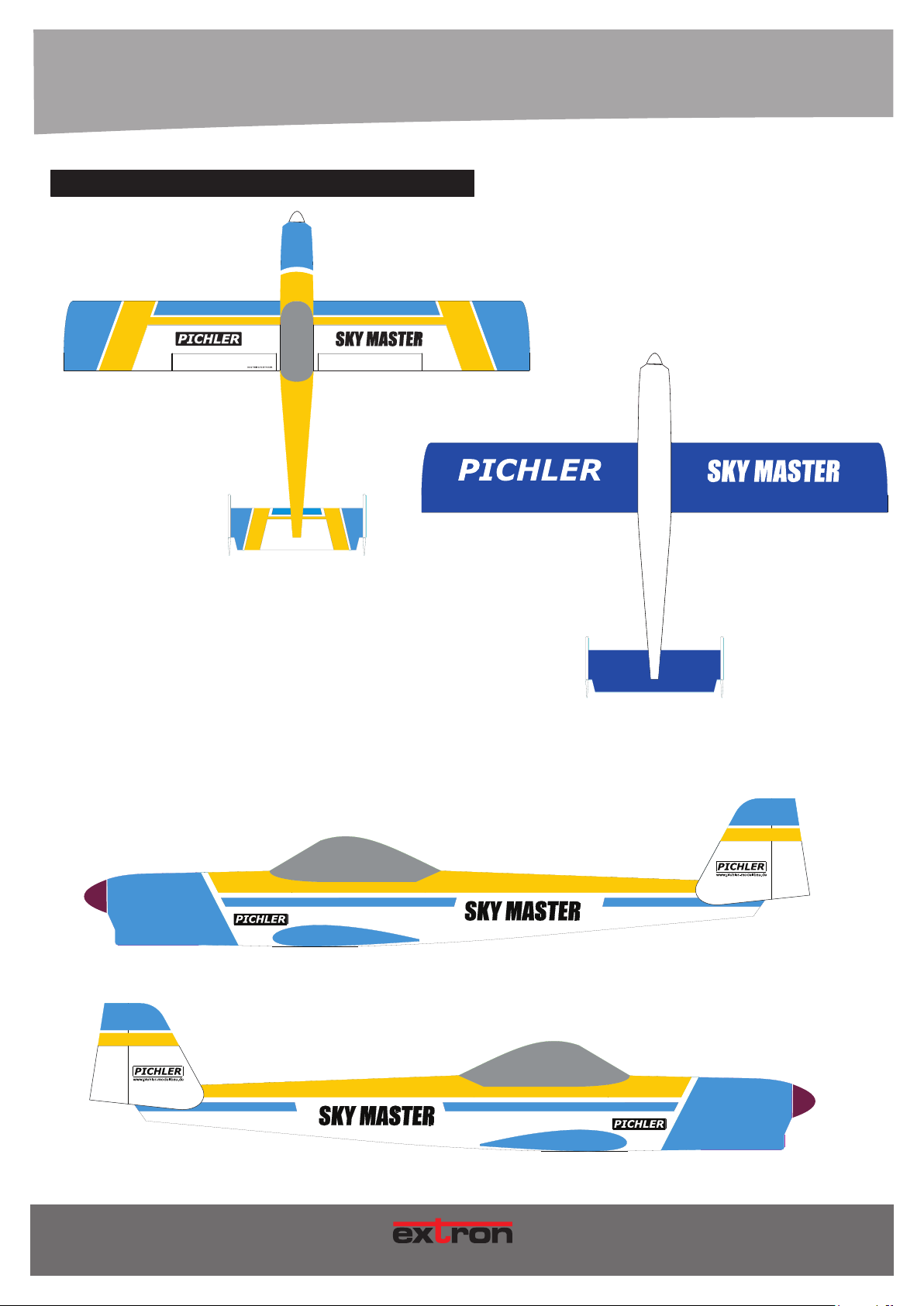
5. HINWEISE ZUR BEDIENUNG / HOW TO USE
RUDERAUSSCHLÄGE / CONTROL THROWS
Top View
NO STEP
SideView: Left
Art.-Nr. / Item-No.
SideView: Right
47
M O D E L L B A U
Page 48
6. ERSATZTEILE / SPARE PARTS
5.1 LAUFRICHTUNG DER RUDER / STEERING DIRECTION OF FLIGHT CONTROLS
Vor dem Erstflug des Modells muss unbedingt die Laufrichtung aller Ruder überprüft werden. / Before the frst flight of the model, the steering
direction must be checked carefully!
HÖHENRUDER / ELEVATOR
Wird der Höhenruderknüppel am Sender nach hinten gezogen, muss das Höhenruder nach oben ausschlagen. Wird der Höhenruderknüppel
nach vorn gedrückt, muss das Höhenruder nach unten ausschlagen. / When you pull the elevator stick, the elevator has to move up, the model
will climb. When you push the elevator stick, the elevator has to move down, the model will decline.
SEITENRUDER / RUDDER
Das Modell wird von hinten betrachtet. Wird der Seitenruderknüppel am Sender nach links bewegt, muss das Seitenruder nach links ausschla
gen. Entsprechend umgekehrt erfolgt der Ausschlag für die andere Richtung. / Take a look to the model from behind. When you move the rudder
stick to the left, the rudder has to move to the left. For the right side it works accordingly.
QUERRUDER / AILERON
Das Modell wird von hinten betrachtet. Wird der Querruderknüppel am Sender nach links bewegt, muss die linke Querruderklappe nach oben
und die rechte Querruderklappe nach unten ausschlagen. Entsprechend umgekehrt erfolgen die Ausschläge für die andere Richtung. / Take a
look to the model from behind. When you move the aileron stick to the left, the left flap has to move up and the right flap has to move down.
For the right side it works accordingly.
MOTOR / MOTOR
Wird der Gasknüppel in die Leerlauf Position gebracht, muss der Motor stillstehen. Bei Vollgas muss der Motor seine maximale Drehzahl
erreichen. / When you move the throttle stick to idle, the motor has to stop completely. Putting the throttle stick to full power, the motor has to
reach its maximum rpm.
5.2 STARTVORGANG / TAKE OFF
• Starten Sie prinzipiell immer gegen den Wind! / Always start the model against the wind!
• Überprüfen Sie die Funktion aller Ruder vor jedem(!) Start. / Check all rudder controls before each(!) start.
•
are near the ground only small control action is recommended.
Steigen Sie in einem flachen Winkel. / Climb in a smooth angle.
•
5.3 LANDEVORGANG / LANDING PROCEDURE
• Drosseln Sie den Motor und fliegen Sie in ca. 40 m Entfernung mit Rückenwind parallel zur Landebahn. / Reduce motor power and fly parallel
to the runway in a distance of about 40 meters.
• Fliegen Sie eine 90° Kurve in Richtung Landebahn und bauen Sie Höhe ab. / Turn 90° to the runway and decline continously.
• Fliegen Sie erneut eine 90° Kurve, Sie fliegen nun direkt auf die Landebahn zu. Turn again 90° to the runway and decline continously. You
are now approaching the runway.
• Lassen Sie das Modell weiter sinken bis das Modell 1 m über der Landebahn schwebt. / Decline until you are about 1 meter over the r
• Ziehen Sie den Höhenruderknüppel etwas stärker und halten Sie ihn gezogen. / Pull the elevator carefully and keep it pulled.
• Je mehr sich das Modell dem Boden nähert, desto mehr muss der Höhenruderknüppel gezogen werden. Da das Modell ständig langsamer
wird, setzt es sich praktisch von allein auf die Landebahn. / The closer you come to the ground the more you have to pull the elevator. As the
model gets slower, it will land more or less automatically.
48
www.extron-modellbau.de
Art.-Nr. / Item-No.
Page 49

6. SERVICE & GEWÄHRLEISTUNG / SERVICE & WARRANTY
SERVICE & GEWÄHRLEISTUNG
Dieses Produkt unterliegt der gesetzlichen Gewährleistung. Die Haftung im Schadensfall ist begrenzt
auf den Wert der Sache bzw. deren Kaufpreis (= in diesem Fall das Modell Commander 3). Füretwaige
Folgeschäden übernehmen wir keine Haftung.
Im Servicefall wenden Sie sich zuerst bitte schriftlich (eMail, Brief oder Fax) mit einer aussagekräftigen
Beschreibung des Problems sowie einer Kopie des Kaufbelegs an untenstehende Adresse. Sie verkürzen damit die Bearbeitungszeit erheblich. Die meisten Fragen und Probleme lassen sich am schnellsten per eMail klären.
UNERLAUBTE RÜCKSENDUNGEN WERDEN NICHT ANGENOMMEN!
extron Modellbau • Lauterbachstrasse 19 • D-84307 Eggenfelden
FAX: +49 (0)8721-508 266 20 • eMail: [email protected]
HINWEIS ZUR BATTERIEVERORDNUNG
Defekte Akkus sind Sondermüll und dürfen nicht über die Mülltonne entsorgt werden. Im Fachhandel, wo Sie die Akkus erworben haben, stehen Batterie- Recycling-Behälter für die Entsorgung bereit.
Der Fachhandel ist zur Rücknahme verpflichtet.
Art.-Nr. / Item-No.
MOD E L L B A U
MOD E L L B A U
49
Page 50
FÜR IHRE NOTIZEN / FOR YOUR NOTES
50
www.extron-modellbau.de
Art.-Nr. / Item-N
Page 51

M O D E L L B A U
SKY MASTER
Art.-Nr.
Copyright by extron Modellbau • D-84307 Eggenfelden
January 20??
Technische Änderungen sind ohne vorherige Ankündigungen möglich! Jeder Nachdruck,
auch auszugsweise, bedarf unserer ausdrücklichen, schriftlichen Genehmigung.
extron Modellbau GmbH
Lauterbachstrasse 19 • D-84307 Eggenfelden
Tel. +49 (0)8721-508 26 60 • Fax: +49 (0)8721-508 266 20 • eMail: [email protected]
51
www.extron-modellbau.de
Art.-Nr. / Item-N
 Loading...