


OV-10 BRONCO
OV-10 BRONCO
Technische Daten
- Spannweite = 1800 mm
- Länge = 1280mm
- Gewicht = ca. 6900g
2
- Flächeninhalt = 57.1dm
2
- Flächenbelastung = 119.1 g/dm
- Flächenprofil = Naca Airfoil
Empfohlener E-Antrieb
- Brushless Antriebsset BOOST 45
- LiPo Akku LEMONRC 4300-3S
Montageanleitung
Instruction Manual book
Specifications
- Wingspan = 1800 mm
- Length= 1280mm
- Weight = approx. 6900g
2
- Wing Area = 57.1dm
2
- Wing Loading = 119.1 g/dm
- Airfoil = Naca Airfoil
Power Set (recommended)
- Brushless Power Set BOOST 45
- LiPo Battery LEMONRC 4300-3S

Inhaltsverzeichnis / Table of Content
Cut off excess.
B
Apply epoxy glue.
Apply threadlocker
(screw cement).
C.A
Apply instant glue
(C.A glue, super glue).
Cut off shaded portion
carefully.
Assemble left and right
sides the same way.
Must be purchased
separately!
Ensure smooth, non-binding
movement when assembling.
Warning!
Set all scerws securely. If they come off during
flight you will lose control of your aircraft!
Pay close attention here.
Drill holes using the stated.
(in this case 1.5mm ).
1
.5mm
Take particular care here.
The number of times
the same way Assembly
(in this case twice).
2
Symbols used throughout this instruction manual, comprise:
Page 2
Instruction Manual Book OV-10 BRONCO
4 Symbols used throughout this instruction
manual, comprise: . . . . . . . . . . . . . . . . . . . . . . . . 2
4 Parts listing (not included). . . . . . . . . . . . . . . . 4
4 Tools & supplies needed. . . . . . . . . . . . . . . . . 4
4 Installing the ailerons and flaps. . . . . . . . . . . . 4
4 Installing the ailerons and flaps servos. . . . . . 4
4 Installing the control horns and linkages . . . . 6
4 Installing the engine mount. . . . . . . . . . . . . . . 8
4 Installing the fuel tank. . . . . . . . . . . . . . . . . . . 8
4 Installing the engine . . . . . . . . . . . . . . . . . . . . 9
4 Installing the throttle . . . . . . . . . . . . . . . . . . . 11
4 Installing the electric motor (ep version). . . . 12
4 Rudder installation . . . . . . . . . . . . . . . . . . . . 13
4 Installing horizontal stabilizer . . . . . . . . . . . . 14
4 Installing the wheel well . . . . . . . . . . . . . . . . 15
4 Installing main gear . . . . . . . . . . . . . . . . . . . 17
4 Electric gear retracts. . . . . . . . . . . . . . . . . . . 19
4 Installing the nose gear . . . . . . . . . . . . . . . . 20
4 Mounting the cowl. . . . . . . . . . . . . . . . . . . . . 24
4 Installing the spinner. . . . . . . . . . . . . . . . . . . 25
4 Plastic parts for fuselage . . . . . . . . . . . . . . . 28
4 Installing the receiver and battery. . . . . . . . . 28
4 Wing attachment, horizontal stabilizer . . . . . 29
4 Installing cockpit fuselage. . . . . . . . . . . . . . . 31
4 Balancing . . . . . . . . . . . . . . . . . . . . . . . . . . . 33
4 Lateral balance . . . . . . . . . . . . . . . . . . . . . . . 34
4 Pre-flight chec. . . . . . . . . . . . . . . . . . . . . . . . 34
4 Control throws . . . . . . . . . . . . . . . . . . . . . . . 34
4 For your radio installation basic connection for
airplane and adjustment of servos. . . . . . . . . . . 35
4 Main gear dimensional detail . . . . . . . . . . . . 36
Deutscher Modellflieger Verband e. V.
Rochusstraße 104-106
53123 Bonn
Telefon: +49 (0) 228 97 85 00
Telefax: +49 (0) 228 978 50 85
eMail: info@dmfv.aero
Internet: www.dmfv.aero
Deutscher Aero Club e.V.
Hermann-Blenk-Str. 28
38108 Braunschweig
Telefon: 0531 23540 - 0
Telefax: 0531 23540 - 11
eMail: info(at)daec.de
Adressen der deutschen Modellsport Dachverbände

EPOXY A
EPOXY B
Page 3
Instruction Manual Book OV-10 BRONCO
# C9110
Brushless Power Set BOOST
Motor + Regler / Motor + ESC
Sonderzubehör für OV-10 Bronco / Accessories for OV-10 Bronco
# C7211 + # C7212
Elektrisches Einziehfahrwerk
Electric Power Retract Kit
# C9481 / x2
LiPo Akku LEMONRC 4300-4S
LiPo Battery LEMONRC 4300-4S
# C5374 MASTER
Fernsteuerset 2.4Ghz
Radio Set 2.4Ghz
# C5638 Servo DS3012MG
(8 Stück erforderlich)
(8 pcs. required)
Nachstehendes Zubehör wurde von uns ausgiebig erprobt und wird für beste Flugeigenschaften
empfohlen. Weitere Informationen und Bestellmöglichkeit unter www.pichler-modellbau.de
These accessories have been extensively tested and are recommended for best flying performance.
For more information please visit www.pichler-modellbau.de
# C6566
MASTER Flight Control 2
Flugstabilisator
Flight Stabilizer
# C5754 / x2
PI-CON Propeller
# C4738
Akku Klettband
Battery Straps
# C6342 Flächenschutztaschen
Protective Wing bags
................. x 4
................. x 1
250mm ...... x 8
400mm .... x 10
1000mm ...... x 1
Servokabel Verlängerungen / Servo Extension Leads
# X3598-200
# C8125
# C9097
# C1393
# C2036
# C2415
# X3571
# X3581

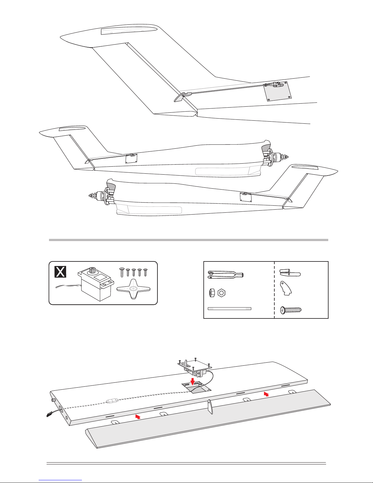
INSTALLING THE AILERONS AND FLAPS.
2) Apply drops of thin CA to the top and bottom of
each hinge. Do not use CA accelerator. After the CA
has fully hardened, test the hinges by pulling on the
aileron.
Temporary pin to
keep hinge centered.
1) Test fit the ailerons to the wing with the hinges. If
the hinges don’t remain centered, stick a pin through
the middle of the hinge to hold it in position.
Flap
Flap
Bottom view
Aileron
B
1
2
C.A
C.A
Secure nylon hinges with instant glue, being
careful not to glue the wing and aileron together.
Align the center line of main wing with aileron.
1
2
Warning!
Make certain the hinges are
adequately secured with glue. if they come loose in
flight accidents may result.
1. Install the rubber grommets and brass eyelets
onto the aileron servos.
2. Using a modeling knife, remove the covering
from over the pre-cut servo arm exit hole on the
aileron servo tray / hatch. This hole will allow the
servo arm to pass through when installing the aileron
pushrods.
3. Place the servo into the servo tray. Center the
servo within the tray and drill 1.5mm pilot holes
INSTALLING THE AILERONS AND FLAPS SERVOS.
through the block of wood for each of the four
mounting screws provided with the servo.
4. Using the thread as a guide and using masking
tape, tape the servo lead to the end of the thread:
carefully pull the thread out. When you have pulled
the servo lead out, remove the masking tape and the
servo lead from the thread.
5. Place the servo into the servo tray/ hatch into the
servo box on the bottom of the wing and drill 1.5mm
pilot holes through the tray and servo box for each of
the four mounting screws. Secure the servo tray in
place using the mounting screws provided.
6. Repeat step # 2 - # 5 to install the second aileron
servo in the opposite wing half.
Page 4
Instruction Manual Book OV-10 BRONCO

For Flap servo.
For Aileron servo.
2 x 10mm Screw
- - - - 16
Warning!
Tie the string.
Pull out servo cord with string.
1
2
2x10mm
1
2
For Aileron.
o
60
Flap
o
90
Aileron
approx.16mm
2mm
4
Aileron and
flap servos.
4
2x10mm Screw
2
For Flap.
For Aileron.
1.5mm
2 mm
2
For Flap.
For Aileron.
Screw
1.5mm
1.5mm
Page 5
Instruction Manual Book OV-10 BRONCO

INSTALLING THE CONTROL HORNS AND LINKAGES.
100mm Push rod
- - 4
M2
- - - 4
- - - - - - - 4
Horn
- - - - - - 4
- - - - - - 4
Flaslink
2mm Nut
1) Working with the aileron linkage for now, thread
one nylon clevis at least 14 turns onto one of the
2mm x 180mm threaded wires.
2) Attach the clevis to the outer hole in the control
horn. Install a silicone tube on the clevis.
3) Locate one nylon servo arm, and using wire
cutters, remove all but one of the arms. Using a
2mm drill bit, enlarge the third hole out from the
center of the arm to accommodate the aileron
pushrod wire.
4) Plug the aileron servo into the receiver and
center the servo. Install the servo arm onto the
servo. The servo arm should be perpendicular to
the servo and point toward the middle of the wing.
5) Center the aileron and hold it in place using a
couple of pieces of masking tape.
6) With the aileron and aileron servo centered,
carefully place a mark on the aileron pushrod wire
where it crosses the hole in the servo arm.
7) Using pliers, carefully make a 90 degree bend
down at the mark made. Cut off the excess wire,
leaving about 6mm beyond the bend.
8) Insert the 90 degree bend down through the
hole in the servo arm. Install one nylon snap
keeper over the wire to secure it to the arm. Install
the servo arm retaining screw and remove the
masking tape from the aileron.
9) Repeat step # 4 - # 8 to install the second
aileron linkage. After both linkages are completed,
connect both of the aileron servo leads using a Yharness you have purchased separately.
Bottom view
Bottom view
B
Horn
4
Page 6
Instruction Manual Book OV-10 BRONCO

Flaslink
Push rod
4
2
Mark the spot to attach
o
Bend 90
1
2
Cut
Silicone tube
5mm
Bottom view
Silicone Tube
M2
2mm Nut
Servo arm
Push rod
6mm
1
Page 7
Instruction Manual Book OV-10 BRONCO

There are two options:
1. Engine mount.
2. Electric motor
INSTALLING THE ENGINE MOUNT
OPTION 1: ENGINE INSTALLATION
Installing the engine mount, fuel tank
To carburetor
fuel inlet
(see front view of fuel tank). Insert and tighten the screw.
Be sure to equip
air vent pipe.
Tubing for
re-fuelling
Not included.
Tygon tubing (Gas). And
silicone tubing (Methanol).
5mm
INSTALLING THE FUEL TANK.
1) The stopper has been pre-assembled at the
factory.
2) Using a modeling knife, cut one length of silicon
fuel line (the length of silicon fuel line is calculated by
how the weighted clunk should rest about 8mm away
from the rear of the tank and move freely inside the
tank). Connect one end of the line to the weighted
clunk and the other end to the nylon pick up tube in
the stopper.
3) Carefully bend the second nylon tube up at a 45
degree angle (using a cigarette lighter). This tube will
be the vent tube to the muffler.
4) Carefully bend the third nylon tube down at a 45
degree angle (using a cigarette lighter). This tube
will be vent tube to the fueling valve.
When the stopper assembly is installed in the
tank, the top of the vent tube should rest just below
the top surface of the tank. It should not touch the top
of the tank.
5) Test fit the stopper assembly into the tank. It may
be necessary to remove some of the flashing around
the tank opening using a modeling knife. If flashing is
present, make sure none of it falls into the tank.
6) When satisfied with the alignment of the stopper
assembly tighten the 3mm x 20mm machine screw
until the rubber stopper expands and seals the tank
opening. Do not over tighten the assembly as this
could cause the tank to split.
7) Using a modeling knife, cut 3 lengths of fuel line.
Connect 2 lines to the 2 vent tubes and 1 line to the
fuel pickup tube in the stopper.
8) Fe ed thr ee li nes t hro ugh t he fue l ta nk
compartment and through the pre-drilled hole in the
firewall. Pull the lines out from behind the engine,
while guiding the fuel tank into place. Push the fuel
tank as far forward as possible, the front of the tank
should just about touch the back of the firewall.
Blow through one of the lines to ensure the fuel lines
have not become kinked inside the fuel tank
compartment. Air should flow through easily.
Do not secure the tank into place permanently
until after balancing the airplane. You may need to
remove the tank to mount the battery in the fuel tank
compartment.
9) Secure the fuel tank.
Silicone tube
Foam ring
Fuel tank
Page 8
Instruction Manual Book OV-10 BRONCO

Fuel tank
Fuel tank
Zip tie
INSTALLING THE ENGINE.
* Locate the long piece of wire used for the throttle
pushrod. One end of the wire has been pre-bend in to
a "Z" bend at the factory. This "Z" bend should be
inserted into the throttle arm of the engine when the
engine is fitted onto the engine mount. Fit the engine
to the engine mount using the screws provided.
3mm Flat washer
- - - - - - - 8
4mm Spring Washer
- - - - - - - 8
3x25mm Cap Screw
- - - - - 8
3 - - 8mm Nut
Engine
mount
500mm Pushrod wire
- - - 2
4x25mm Cap Screw
- - - - - 8
4mm asherFlat w
- - - - - - - 8
Page 9
Instruction Manual Book OV-10 BRONCO

Pushrod wire
Secure
4mm Spring
4mm asherFlat w
4x25mm Secure
125mm
2
3x25mm
3mm asherFlat w
3mm Nut
Page 10
Instruction Manual Book OV-10 BRONCO

2
Screw
o
90
approx.16mm
2mm
Linkage stopper
4x4mm
2x10mm
2mm
Pushrod wire
Adjust the throttle input
(transmitter throttle stick),
throttle trim movement and the
carburattor opening to the
suitable position and screw in
the 4x4mm set screw.
INSTALLING THE THROTTLE
2) Plug the throttle servo into the receiver and turn
on the radio system. Check to ensure that the
throttle servo output shaft is moving in the correct
direction. When the throttle stick is moved forward
from idle to full throttle, the throttle barrel should
also open and close using this motion. If not,
reverse the direction of the servo, using the
transmitter.
3) Slide the adjustable metal connector / servo
arm assembly over the plain end of the pushrod
wire. Position the throttle stick and the throttle trim
at their lowest positions.
4) Manually push the carburator barrel fully
closed. Angle the arm back about 45 degree from
center and attach the servo arm onto the servo.
With the carburator barrel fully closed, tighte the
set screw in the adjustable metal connector.
5) Remove the excess throttle pushrod wire using
wire cutters and install the servo arm retaining
screw.
Connector - - - - 2
1) Install one adjustable metal connector through
the third hole out from the center of one servo arm,
enlarge the hole in the servo arm using a 2mm drill
bit to accommodate the servo connector. Remove
the excess material from the arm.
After installing the adjustable metal connector
apply a small drop of thin C/A to the bottom nut.
This will prevent the connector from loosening
during flight.
Throttle Servo
2
Throttle servo
Fuel tank
Page 11
Instruction Manual Book OV-10 BRONCO

OPTION 2: INSTALLING THE ELECTRIC MOTOR (EP VERSION)
- - - - - 8
10x40mm Aluminum
Mount Nut
- - - - - 8
4mm Washer
- - - - - 8
4mm Spring Washer
- - - - - 8
4mm Washer
- - - - - 8
- - 8
4x60mm Cap Screw
3x15mm Cap Screw
- - - - - 8
3mm Spring Washer
- - - - - 8
3x15mm
3mm Spring
4x60mm
4mm Spring
4mm Washer
4mm Washer
10x40mm
Page 12
Instruction Manual Book OV-10 BRONCO

RUDDER INSTALLATION
1) Hinges and servo for Rudder are glued the
same way as the aileron before (see page 6, 7).
2) Control horn and linkages for Rudder are
installed the same way as the aileron before
(see page 8, 9).
300mm Push rod
- - 2
M2
- - - 2
- - - - - - - 2
2mm Nut
Horn
- - - - 2
- - - - 2
Flaslink
2 x 10mm Screw
- - 8
Rudder pushrod
Rudder servo
Horn
Page 13
Instruction Manual Book OV-10 BRONCO
INSTALLING HORIZONTAL STABILIZER
1) Hinges and servo for Elevator are glued the
same way as the aileron before (see page 6, 7).
2) Control horn and linkages for Elevator are
installed the same way as the aileron before
(see page 8, 9).
100mm Push rod
- - 1
M2
- - - 1
- - - - - - - 1
2mm Nut
Horn
- - 1
- - - 1
Flaslink
2x10mm Screw
- - - 4
2x10mm
Page 14
Instruction Manual Book OV-10 BRONCO

INSTALLING THE WHEEL WELL
Fuselage Bottom Side
2
C.A
2
* Using a modeling knife, carefully
re mo ve the fi lm covering from the
f gear tray. Make sure that you do uselage
not remove any wood.
W
HE
EL W
EL
L
5mm
5mm
Cut the plastic
Cut the plastic
Page 15
Instruction Manual Book OV-10 BRONCO

Fuselage Bottom Side
C.A
45mm Aluminium
- - - - 2
B
45mm Aluminium
Page 16
Instruction Manual Book OV-10 BRONCO

INSTALLING MAIN GEAR.
Main gear
Nose gear
5x30mm
5mm Washer
4x4mm
ELECTRIC NOT INCLUDED.
3x6mm Button Screw
- - - - - - - - 1
5x30mm Cap Screw
- - - - - - 3
3x15mm Screw
- - - - 12
5mm Washer
- - - - - - - - 3
350mm Cable
- - 2
- - - - 2
M3
- - - - - - - 4
- - - - - 2
- - - - - - 2
3mm Nut
Cab link
ONLY INCLUDING OLEO STRUTS.
Nose gear
Main gear
3x6mm
Spring
65mm Wheels.
5.1mm hold
75mm Wheels.
5.1mm hold
5x40mm Pin
5x50mm
Landing gear mount.
Page 17
Instruction Manual Book OV-10 BRONCO
# C7211 + # C7212
Elektrisches Einziehfahrwerk
Electric Power Retract Kit
Wir empfehlen den Einbau unseres Elektrischen Einziehfahrwerks
das Sie unter der Bestellnummer C7211 und C7212 bestellen können
unter www.shop.pichler.de
We recommend installing our electric retract gear which have the
order number C7211 and C7212 from our webstore at
www.shop.pichler.de

C.A
3x15mm
Fuselage Bottom Side
2
.5mm
Screw
Screw the gear in position
2
THERE ARE TWO OPTIONS:
OPTION 1: MAIN GEAR STRUTS
Screw
Page 18
Instruction Manual Book OV-10 BRONCO

OPTION 2: ELECTRIC GEAR RETRACTS
Screw
2
.5mm
Screw the gear in position
Screw
Page 19
Instruction Manual Book OV-10 BRONCO

INSTALLING THE NOSE GEAR
OPTION 1: NOSE GEAR STRUT
Screw
Cable rod
Crimp
1
2
3
4
5
Page 20
Instruction Manual Book OV-10 BRONCO

3x6mm
Spring
Screw
1
2
3
4
5
OPTION 2: ELECTRIC GEAR RETRACTS
2
.5mm
3x15mm
Screw
Screw the gear in position
Page 21
Instruction Manual Book OV-10 BRONCO

2
.5mm
3x15mm
Screw the gear in position
Screw
Screw
3x6 mm Screw
Cable rod
Crimp
Screw the gear in position
Page 22
Instruction Manual Book OV-10 BRONCO

Servo nose gear
approx.16mm
2mm
Servo nose gear
o
90
1
2
3
4
5
Cab link
3mm
M3
Page 23
Instruction Manual Book OV-10 BRONCO

3 x 12mm Screw
- - - - 12
MOUNTING THE COWL
1) Remove the muffler and needle valve assembly
from the engine. Slide the fiberglass cowl over the
engine.
2) Measure and mark the locations to be cut out
for engine head clearance, needle valve, muffler.
Remove the cowl and make these cutouts using a
rotary tool with a cutting disc and a rotary sanding
drum attachment.
3) Slide the cowl back into place. Align the front of
the cowl with the crankshaft of the engine. The
front of the cowl should be positioned so the
crankshaft is in the middle of the precut opening.
Hold the cowl firmly in place using several pieces
of masking tape.
4) While holding the cowl firmly in position, drill
four 1,6mm pilot holes through both the cowl and
the side edges of the firewall.
5) Using a 3mm drill bit, enlarge the four holes in
the cowling.
Enlarging the holes through the cowl will
prevent the fiberglass from splitting when the
mounting screws are installed.
6) Slide the cowl back over the engine and secure
it in place using four screws.
7) Install the muffler. Connect the fuel and pressure
lines to the carburator, muffler and fuel filler valve.
Tighten the screws completely.
3x12mm Screw
2
mm
15mm
Page 24
Instruction Manual Book OV-10 BRONCO

2
6 x 45mm
- - - 2
2
C.A
2
6 x 45mm
Antenna
Antenna
Page 25
Instruction Manual Book OV-10 BRONCO

Warning!
* Install the spinner back-plate, propeller and spinner
cone. The spinner cone is held in place using two screws.
The propeller should not touch any part of the
The propeller should not touch any part of the spinner
cone. If it dose, use a sharp modeling knife and carefully
trim away the spinner cone where the propeller comes in
contact with it.
INSTALLING THE SPINNER.
2
2
3x15mm- - 4
- - - - 2
- - - - 2
2
mm
3x12mm
Screw
2
2
mm
3x12mm
Screw
3mm
Page 26
Instruction Manual Book OV-10 BRONCO

2
3x15mmScrew
Page 27
Instruction Manual Book OV-10 BRONCO

3 x 10mm Screw
- - - - 12
PLASTIC PARTS FOR FUSELAGE.
INSTALLING THE RECEIVER AND BATTERY.
INSTALLING THE SWITCH
1) The switch should be mounted on the fuselage
side, opposite the muffler, close enough to the
receiver so the lead will reach. Use the face plate
of the switch cut out and locate the mounting
holes.
2) Cut out the switch hole using a modeling knife.
Use a 2mm drill bit and drill out the two mounting
holes through the fuselage side.
3) Secure the switch in place using the two
machine screws provided with the radio system.
1) Plug the servo leads and the switch lead into
the receiver. You may want to plug an aileron
extension into the receiver to make plugging in the
aileron servo lead easier when you are installing
the wing. Plug the battery pack lead into the
switch.
2) Wrap the receiver and battery pack in the
protective foam to protect them from vibration. Use
a rubber band or masking tape to hold the foam in
place.
Do not permanently secure the receiver and
battery until after balancing the model.
3x10mm Screw
25mm
Page 28
Instruction Manual Book OV-10 BRONCO

544mm
Aluminium tube.
19mm
384mm
WING ATTACHMENT, HORIZONTAL STABILIZER .
Fuselage top side
Switch
ON
OFF
Fuselage top side
Switch
Battery
for Receiver
Zip tie
Zip tie
Battery
for Motor
Receiver
Page 29
Instruction Manual Book OV-10 BRONCO

4 x 20mm
- - - 2
Screw in position.horizontal stabilizer
4x20mm
4x20mm
Fuselage top side
4x20mm
Screw
4x20mm
Screw
Attach the wings to the joiner tube and
secure the wing panels to the fuselage.
4x15mm
4x15mm
Page 30
Instruction Manual Book OV-10 BRONCO

INSTALLING COCKPIT FUSELAGE
Position the canopy so the rear frame on the
canopy is aligned with the rear edge of the
cockpit opening. Use canopy glue to secure the
canopy to the canopy hatch. Use low-tack tape
to hold the canopy in position until the glue fully
cures. Wrap the tape completely around the
canopy hatch.
Fuselage top side
Screw
Screw
1
Main wing must be inserted and attached completely.
1
Page 31
Instruction Manual Book OV-10 BRONCO

B
Open/Close
Page 32
Instruction Manual Book OV-10 BRONCO

Adhesive tape.
Open/Close
BALANCING
1) It is critical that your airplane be balanced
correctly. Improper balance will cause your plane to
lose control and crash.
THE CENTER OF GRAVITY IS LOCATED 85MM
BACK FROM THE LEADING EDGE OF THE
WI NG. AT THE FU SE LA GE. BALANCE A
PLANE UPSIDE DOWN WITH THE FUEL
TANK EMPTY.
2) Mount the wing to the fuselage. Using a couple of
pieces of masking tape, place them on the top side of
the wing 85mm back from the leading edge, at the
3) Turn the airplane upside down. Place your
fingers on the masking tape and carefully lift the
plane.
4) If the nose of the plane falls, the plane is nose
heavy. To correct this first move the battery pack
further back in the fuselage. If this is not possible or
does not correct it, stick small amounts of lead
weight on the fuselage under the horizontal
stabilizer. If the tail of the plane falls, the plane is tail
heavy. To correct this, move the battery and receiver
forward or if this is not possible, stick weight into the
firewall. When balanced correctly, the airplane
should sit level or slightly nose down when you lift it
up with your fingers.
CG
85 mm
Page 33
Instruction Manual Book OV-10 BRONCO
Schwerpunkt

LATERAL BALANCE
After you have balanced a plane on the C.G.
You should laterally balance it. Doing this will
help the airplane track straighter.
1) Turn the airplane upside down. Attach one
loop of heavy string to the engine crankshaft and
one to the tail wheel wire. With the wings level,
carefully lift the airplane by the string. This may
require two people to make it easier.
2) If one side of the wing fall, that side is heavier
than the opposite. Add small amounts of lead
weight to the bottom side of the lighter wing half's
wing tip. Follow this procedure until the wing stays
level when you lift the airplane.
1) We highly recommend setting up a plane using
the control throws listed.
2) The control throws should be measured at the
widest point of each control surface.
3) Check to be sure the control surfaces move in the
correct directions.
CONTROL THROWS
— Aileron: 12 m m up 12 mm down
— Elevator: 14 mm up 14 mm down
— Rudder: 25 mm right 25 mm left
— Flap: 20 mm down
Low rate:
PRE-FLIGHT CHECK
1) Completely charge your transmitter and
receiver batteries before your first day of flying.
2) Check every bolt and every glue joint in your
plane to ensure that everything is tight and well
bonded.
3) Double check the balance of the airplane.
4) Check the control surface.
5) Check the receiver antenna. It should be fully
extended and not coiled up inside the fuselage.
6) Properly balance the propeller.
20mm
Flap control
12mm
12mm
Aileron control
14mm
14mm
Elevator
25mm
25mm
Rudder control
Page 34
Instruction Manual Book OV-10 BRONCO
Ruderausschläge
Querruder
Höhenruder
Seitenruder
Landeklappen

Example of connection
FOR YOUR RADIO INSTALLATION
BASIC CONNECTION FOR AIRPLANE AND ADJUSTMENT OF SERVOS
Engine
Aileron
Rudder
Rudder
Elevator
Elevator Servo
Aileron
Throttle Servo
Throttle Servo
Aileron Servo
Aileron Servo
Electric retract
Electric retract
Electric retract
Flap Servo
Flap
Flap Servo
Flap
Cable rod
Rudder Servo
Rudder Servo
Nose gear servo
Receiver
Y-Harness
Battery (Receiver)
Switch
For more information, refer to radio system instruction manual.
Follow instruction manual of Engine and Battery.
Suggestion: Use a sharp
secewdriver to take the red
cable out from (only one ESC)
the BEC connector, and
then insulate it with a bit of
electrical tape for futher use.
Motor
Motor
ESC
B
A
TTE
RY
ESC
B
A
TTE
RY
Take the red line out
Receiver
Page 35
Instruction Manual Book OV-10 BRONCO
Rote Leitung stillegen

44mm
41mm
51mm
31mm
MAIN GEAR DIMENSIONAL DETAIL
MAIN GEAR STRUTS
NOSE GEAR STRUTS
5.1mm hold
152mm
40mm
75mm
5mm
5.1mm hold
122mm
50mm
65mm
5mm
41mm
21mm
25mm
LANDING GEAR MOUNT.
Page 36
Instruction Manual Book OV-10 BRONCO
 Loading...