


Systematic ventilation.
COMFORT
VENTILATION
EN13141-7:2010
EU Regulation
1253/2014
ErP
20 18
OPERATING AND
INSTALLATION INSTRUCTIONS
SYSTEM VENTECH LG 500
The specified energy ecienc y
is applicable when controlled to
local re quirements and is valid
up to the spe cified maximum air
flow volume.

Contents
1 Introduction ............................................................................................................................................. 4
2 General .................................................................................................................................................... 4
2.1 Use in compliance with the intended use .................................................................................................. 5
2.1.1
Intended use
............................................................................................................................................................ 5
2.1.2
Stipulations for operation with fireplaces
................................................................................................................. 6
2.1.3
Stipulations in connection with extractor hoods
........................................................................................................ 6
2.2 Liability .................................................................................................................................................... 6
2.3 Warranty .................................................................................................................................................. 6
3 Safety ...................................................................................................................................................... 7
3.1 Symbols used ........................................................................................................................................... 7
3.2 Safety regulations .................................................................................................................................... 8
3.2.1
General
.................................................................................................................................................................... 8
3.2.2
Setting up the unit
.................................................................................................................................................... 8
3.2.3
Electrical connection work
....................................................................................................................................... 9
3.2.4
Operation of the system
........................................................................................................................................... 9
4 Functioning of the ventilation system .................................................................................................. 10
4.1 System description ................................................................................................................................. 10
4.2 Possibilities of system expansions for frost protection ........................................................................... 11
4.2.1
Earth heat exchanger (factory settings)
.................................................................................................................. 11
4.2.2
Brine geothermal energy with optional cooling function (factory setting)
................................................................ 12
4.2.3
PTC low temperature preheater battery factory setting
.......................................................................................... 13
4.2.4
Anti-frost protection by shutting down the supply air fan
........................................................................................ 13
4.3 System expansion for the purpose of external auxiliary heating ............................................................. 14
4.3.1
With external warm water heater battery (factory setting)
...................................................................................... 14
4.3.2
Needs-based system operation - CO2 control
.......................................................................................................... 14
4.4 Ventilation unit ....................................................................................................................................... 15
4.4.1
Description
............................................................................................................................................................ 15
4.4.2
Advantages and features
........................................................................................................................................ 15
4.4.3
Layout of the unit
................................................................................................................................................... 16
4.4.4
Versions
................................................................................................................................................................. 18
4.4.5
Dimensions
............................................................................................................................................................ 18
4.5 Safety devices ........................................................................................................................................ 19
5 Technical specifications ....................................................................................................................... 19
5.1 Unit specifications .................................................................................................................................. 19
5.2 Characteristic external pressure increase - air volume flow with volume flow constant function ........... 20
5.3 Characteristic external pressure increase - air volume flow without volume flow constant function ...... 20
5.4 Acoustic specifications ........................................................................................................................... 21
6 Operator control unit ............................................................................................................................ 21
6.1 General information ............................................................................................................................... 21
6.2 Control unit "
KOMFORT-G
" ...................................................................................................................... 21
6.2.1
Buttons on the control unit "KOMFORT-G"
............................................................................................................... 22
6.2.2
Representation on the display
................................................................................................................................ 22
6.2.3
Special menu 1 – Operating hour counter (only for specialist installers)
................................................................. 24
6.2.4
Special menu 2 - Language settings, basic ventilation, volume flows and fan speed IV
............................................ 24
7 Power unit ............................................................................................................................................. 25
7.1 Configuration and diagnosis via the PC software (only for specialist installers) ...................................... 25
7.1.1
Connecting the power section to a PC
..................................................................................................................... 25
7.1.2
Software overview
................................................................................................................................................. 26
8 Messages/Faults .................................................................................................................................. 26
8.1 Operating messages on control unit "
KOMFORT-G
" ................................................................................. 26
8.1.1
Deletion of the filter message after a requested filter change
................................................................................. 26
8.1.2
Deletion of the filter message after a premature filter change
................................................................................ 26
8.2 Malfunction messages on control unit "
KOMFORT-G
" .............................................................................. 27
OPERATING AND INSTALLATION INSTRUCTIONS SYSTEM VENTECH LG 500
PAGE 2

9 Scope of delivery, transport, storage and disposal ............................................................................ 28
9.1 Scope of supply ..................................................................................................................................... 28
9.2 Transport and Packaging ....................................................................................................................... 28
9.3 Storage .................................................................................................................................................. 28
9.4 Waste disposal ...................................................................................................................................... 28
10 Installation ........................................................................................................................................... 29
10.1 Prerequisites for installation of the unit ................................................................................................. 29
10.2 Device installation ................................................................................................................................. 30
10.2.1
Setting up the ventilation unit - free-standing installation
....................................................................................... 30
10.2.2
Wall mounting
........................................................................................................................................................ 30
10.2.3
Production of the condensate water connection
..................................................................................................... 30
10.2.4
Connection of air lines and components
................................................................................................................. 31
10.3 Electrical connection.............................................................................................................................. 31
10.3.1
Cable leadthroughs
................................................................................................................................................ 32
10.3.2
Connection between the operator control unit and power unit
................................................................................ 32
10.3.3
Installation of the operator control unit
.................................................................................................................. 32
10.3.4
Circuit diagram
...................................................................................................................................................... 33
10.3.5
Mains connection and replacement of the unit’s internal fuse
................................................................................. 36
10.3.6
Connecting a water re-heater battery
..................................................................................................................... 37
10.4 Initial startup ......................................................................................................................................... 37
11 Servicing and cleaning ......................................................................................................................... 38
11.1 Safety directions .................................................................................................................................... 38
11.2 Customer service ................................................................................................................................... 38
11.3 Service instructions for the user ............................................................................................................ 38
11.3.1
Air filters
............................................................................................................................................................... 38
11.4 Service instructions for the specialized installing company ................................................................... 39
11.4.1
Heat exchanger with bypass flap
............................................................................................................................ 39
11.4.2
Fans
...................................................................................................................................................................... 39
11.4.3
Electrical PTC preheater battery (optional)
............................................................................................................. 40
11.4.4
Unit’s housing - internal cleaning
........................................................................................................................... 40
11.4.5
Condensate drainage
............................................................................................................................................. 40
11.4.6
Service table
.......................................................................................................................................................... 41
12 Spare parts and accessories ............................................................................................................... 42
12.1 Control elements ................................................................................................................................... 42
12.2 System components .............................................................................................................................. 42
12.3 Air filters ............................................................................................................................................... 42
13
Subject to change ................................................................................................................................. 42
14
Product fiche......................................................................................................................................... 43
15 EG-Konformitätserklärung (EC Declaration of Conformity) ............................................................... 44
OPERATING AND INSTALLATION INSTRUCTIONS SYSTEM VENTECH LG 500
PAGE 3

1 Introduction
Dear customer, thank you for your decision to purchase the compact ventilation unit LG 500 System
VENTECH.
The compact ventilation unit LG 500 System VENTECH is a state-of-the-art device. Its convincing features
are its high degree of economy, operator friendliness and operational safety.
To operate your compact ventilation unit safely, properly, and economically, please carefully read and comply
with these operating instructions.
Use the ventilation unit only in perfect condition, in compliance with the intended use, in a manner that is
safety and
danger conscious and in compliance with all information provided in these instructions. If you have
any queries or spare parts orders, please have the device type and serial number (see type plate on the
device) at hand.
Please contact us if you have any further queries or you have lost the documentation:
2 General
This chapter contains general information on the compact ventilation unit LG 500 System VENTECH with
control unit type "
KOMFORT-G
".
READ THESE INSTRUCTIONS CAREFULLY BEFORE INITIAL STARTUP OF THE UNIT!
These instructions contain advice and information about the safe operation, installation, service and
maintenance of the compact ventilation unit LG 500 System VENTECH. It also serves as a reference for service
work so that this can be performed in a responsible manner. Please keep these operating instructions in a
safe place where they are always accessible. Any troubleshooting or work on the compact ventilation unit
must only be performed by an installation company (specialists). We are continuously improving and
developing our products. Your device may therefore differ slightly from the one referred to in these
instructions.
Subject to change without notice:
These instructions have been drawn up with the greatest care. However, no rights may be derived from them.
We constantly make every effort to make technical improvements to and optimizations of our products and
reserve the right to partially or wholly modify the units or technical specifications without prior notice.
For the compact ventilation unit LG 500 System VENTECH, our "General Terms and Conditions" in the
applicable version apply.
OPERATING AND INSTALLATION INSTRUCTIONS SYSTEM VENTECH LG 500
PAGE 4

The compact ventilation unit LG 500 System VENTECH, together with all the
optional system components cited in this description, has been subjected by TÜVAUSTRIA Services GmbH, Testing, Inspection and Certification Centre/Vienna to
a safety test and inspection in accordance with the relevant product requirements,
standards and directives. The mark approval certificate No. 0010-PS/PZW-EX0067-2010 of 8 March 2011 and test reports No. 2010-PS/PZW-EX-0067 and No.
M/EMV-10/220 confirm that the requirements of the relevant test points with the
optional system accessories are met, on the condition that the requirements of
these operating instructions are observed and adhered to
.
2.1 Use in compliance with the intended use
2.1.1 Intended use
The compact ventilation unit LG 500 System VENTECH is intended for installation into air treatments systems
with an adjustable air volume flow of 550 m³/h for the controlled mechanical ventilation of living areas and
rooms with similar purpose, such as seminar rooms and small offices.
The entire living area is pro
vided with supply air and exhaust air ventilation by installing a mechanical,
controlled ventilation system for apartments. In this process there is a controlled air supply with conditioned
and filtered outdoor air in the supply air zones. Odours and humid indoor air are taken out of the extract air
zone.
The purpose of the controlled mechanical ventilation of living areas is to improve air quality and to reduce
heating requirements through the use of a highly efficient heat recovery system as well as influencing indoor
air humidity.
The application range and intended use of the device is limited to use in indoor air treatment systems for
exhausting consumed air and supplying fresh, temperate outdoor air at a maximum conveying temperature of
-15 °C to +35 Ԩ. In addition, the conveyed air must be free of aggressive vapours and wear-indu
cing
mat
erials. Any other application shall be deemed to be diverting from the intended use. The manufacturer
shall assume no further liability for any damages or consequential damages resulting from non-intended use.
Intended use also includes observing our prescribed operating and installation instructions. This unit, which is
accessible for the general public, is intended for installation in residential or commercial buildings. The device
is used for mechanical ventilation of indoor air and also for air reheating in conjunction with a heater battery.
This device is not intended to be used by people (including children) with limited physical, sensory, or mental
capabilities or with a lack of suitable experience and/or knowledge, unless supervised by a person who is
responsible for their safety or from whom they receive instructions on how to use the device.
The unit is not suitable for installation in the open air and must be installed in suitable and temperaturecontrolled indoor rooms. The ventilation unit is not suitable for drying out new-build properties. When the
device is shut down, ensure that no air circulation can occur through the device.
The compact ventilation unit LG 500 System VENTECH is not a ready-to-use product. It must not be put into
operation until it has been properly installed and connected in the indoor air treatment system. Only qualified,
assigned personnel may work on and with the device.
Any individual who transports, sets up or works on the device must have read and understood these
operating instructions, particularly Chapter 3 "Safety Instructions". In addition, the end user has to
be informed of any dangers that might occur.
OPERATING AND INSTALLATION INSTRUCTIONS SYSTEM VENTECH LG 500
PAGE 5

2.1.2 Stipulations for operation with fireplaces
Safety instructions and standards must be observed when using the device simultaneously with fireplaces
consuming indoor air. In the case of indoor air dep
endent fireplaces the combustion air supply for the
fireplace has to be provided separately.
Proper operation of ventilation systems based on the central “Compact ventilation unit LG 500 System
VENTECH” ventilation system requires that existing combustion air or waste gas ducts are isolated from
heating systems dependent on room air.
The ventilation unit LG 500 System VENTECH may only be installed in rooms, apartments and user units of a
comparable size in which indoor air dependent fireplaces are installed, if the simultaneous operation of
indoor air dependent fireplaces for liquid or gaseous fuels and of the apartment’s ventilation system is
prevented or the exhaust gas conveyance of the indoor air dependent fireplace is monitored by special safety
devices.
If the negative pressure in the room where the fireplace is installed is 4 Pa greater than the external pressure,
it must be ensured that the extract air system switches off automatically and reliably. In such cases, the input
"E3 fireplace mode" provided for this purpose can be used. When the contact is closed, the ventilation unit is
switched off immediately and "fireplace mode" is displayed on the control panel. When the contact is opened,
the ventilation unit returns to its original state.
2.1.3 Stipulations in connection with extractor hoods
On account of the heavy load and irregular operation the extract air of any kitchen extractor hood present
must not be integrated into the apartment’s ventilation system. The extract air from such extractor hoods
should be removed separately out of the roof via an exhaust air line. The supply air is provided separately, e.g.
via the window ventilation.
If an extractor hood is being operated without separate introduction of the supply air, the air volume balance
in the apartment is no longer balanced and the proper functioning of the apartment’s ventilation system is not
ensured (odour entrainment etc.). One possibility is to operate the extractor hood with adequate air filtering in
recirculated air mode.
2.2 Liability
The compact ventilation unit LG 500 System VENTECH has been developed and manufactured for use in the
controlled mechanical ventilation of living areas and rooms with a similar purpose, such as seminar rooms
and small offices.
Any other use is considered to be an improper use and can lead to personal injury or damage to the compact
ventilation unit LG 500, for which the manufacturer cannot be held liable. In the event of the following the
manufacturer is liable for no damage whatsoever:
non-compliance with the safety, operating and servicing instructions listed in these operating a
nd
installation instructions
the installation of replacement parts that are not supplied by the manufacturer, whereby the
responsibility for the use of such replacement parts lies completely with the system installer/fitter.
normal wear
2.3 Warranty
The warranty begins with initial startup, at the latest, however, one month after delivery has taken place. The
warranty covers the pure replacement of materials only and does not include any claims for the
compensation of services. It applies only if there is proof of appropriately performed servicing in accordance
with our regulations and by a licensed company that specializes in installation work.
The warranty claim extends for a maximum period of 24 months after installation of the compact ventilation
unit LG 500 System VENTECH, however, up to a maximum of 30 months after the date of manufacture.
OPERATING AND INSTALLATION INSTRUCTIONS SYSTEM VENTECH LG 500
PAGE 6

Warranty claims can be asserted only for material and/or design defects that have occurred during the
warranty term. In the case of a warranty claim, the compact ventilation unit LG 500 System VENTECH may not
be removed without prior written approval of the manufacturer. The manufacturer accords a warranty on
spare parts only if they have been installed by an installer who is recognized by the manufacturer.
The warranty shall expire automatically at the end of the warranty period, or in the case of improper
operation, such as operating without filters, installation of parts not supplied by the manufacturer, or where
non-approved changes or modifications have been made to the system.
Failure to comply with these Operating and Installation Instructions will automatically void all warranties.
3 Safety
Read these operating
and installation instructions carefully and observe the safety instructions for
installation work, commissioning or for general work or maintenance performed on the device.
Retain these operating and installation instructions during the entire service life of the device and keep them
in an easily-accessible location for future reference.
The safety instructions, warnings, comments and directions described in these operating instructions must
always be observed.
The specifications stated in this document may not be modified.
Non-observance of these safety instructions, warnings, comments and directions can result in physical injury
or damage to the compact ventilation unit.
We recommend purchasing a maintenance contract to ensure that the device is inspected and maintained at
regular intervals. Your supplier can provide you with the addresses of approved specialists/installers in your
area.
3.1 Symbols used
The following safety symbols indicate text passages that warn against dangers and sources of danger. Please
familiarise yourself with these symbols!
Caution/Important information!
Caution! The non-observance of this warning can lead to injury or danger to life and limb and/or
damage to the unit.
Caution - dangerous electrical voltage! The non-observance of this warning can lead to injury or
danger to life and limb.
OPERATING AND INSTALLATION INSTRUCTIONS SYSTEM VENTECH LG 500
PAGE 7

3.2 Safety regulations
3.2.1 General
Installation, commissioning, maintenance, and repair must be performed by an authorised specialist
(heating specialist firm/installation specialist firm).
The local national regulations and standards apply without restriction beyond these operating installation
instructions in respect of operation of the device. Ensure that your system installer/fitter shows you how to
operate the device and the control unit after installation. Use of the ventilation unit may only take place in
accordance with the use set out in point 2.1 ‘Use in compliance with the intended use`.
All safety and danger notices attached to the device and described in these instructions must be observed. In
the event of any malfunctions, shut down the unit immediately and secure it suitably against being switched
back on. Any malfunction of the device must be rectified immediately. After servicing and maintenance work,
the operating safety of the device should be re-established by expert personnel.
The attachment or installation of additional parts and components is not permitted. Any modifications or
changes to the compact ventilation unit LG 500 System VENTECH are prohibited. Only original replacement
parts may be used. Modifications and adaptations to the ventilation unit are not permitted and release the
manufacturer from any warranty and liability. Make sure that children do not play with the unit.
3.2.2 Setting up the unit
The national and local regulations must be observed for installation and setup.
The unit must be installed only in compliance with the national installation regulations. Installation
shall be performed in accordance with the general, locally valid construction, safety and installation
regulations of the appropriate local authority or of the water and electricity company and other institutions.
The unit may be installed only in frost-free and dry rooms. The room temperature in the set-up room must
have a continuous temperature between a minimum of +5 Ԩ and a maximum of +40 Ԩ. The device is intended
for free-standing installation or wall mounting and may only be set up when there is suitable load-bearing
floor or wall construction. No vibrations must be allowed to affect the unit. A suitable water drain with
effective drain trap (siphon) must be provided for discharging condensate water accumulated during
operation of the device.
Installation work for the water, heating and condensate water connections may only be performed by a
professional. Proper installation is essential for ensuring the water-tightness and effectiveness of the
condensate discharge line and in order to prevent damage to the building. The condensate drainage has to be
checked for operability by means of an on-site inspection prior to initial startup and after any servicing work.
The permitted maximum expectable load has to be heeded for transportation of the unit. System components
of the ventilation system, such as air lines, that are installed in potentially unheated areas must be suitably
insulated to prevent heat loss or condensate water formation (where temperatures fall below the dew point).
The locally-applicable construction and fire prevention provisions, regulations and standards must be
adhered to. Appropriate suitable measures for erection of the unit, e.g. the installation of fire dampers in air
pipes etc., may have to be taken. Take into consideration the ambient influences and do not install the
ventilation unit in the vicinity of combustible liquids or gases, in swimming pools or in areas subject to the
influence of chemicals.
OPERATING AND INSTALLATION INSTRUCTIONS SYSTEM VENTECH LG 500
PAGE 8

3.2.3 Electrical connection work
Electrical connection work and work on the electrical parts of the system may be performed only by
authorized skilled electricians in compliance with national and local regulations.
Before opening the device and during all work on the device, such as maintenance work, repairs etc., the
device must be disconnected from power (power supply disconnected at all poles) and must be secured
against being switched on again for the duration of the work.
The compact ventilation unit LG 500 is designed for a voltage supply of 230 V/50 Hz/16 A. The device is not
designed for electrical connection to a three-phase supply network with 400 V/50 Hz! Refrain from any
manner of working that impairs the safety of the unit. For safe operation, safety devices may not be
disassembled or placed out of operation.
The electrical equipment and the warning and protection devices of the unit have to be regularly checked for
perfect operability. The device must be placed out of operation immediately if malfunctions occur in the
electrical supply or defects are detected, such as loose connections or melted cables.
If the mains power cable of the device is damaged or defective, it must be repaired immediately to prevent
risks. Only genuine fuses with the prescribed current strength and dimensions may be used. Operation of the
unit is prohibited until safe operation of the system has been re-created.
Only qualified electrical specialists may determine the cause of occurring defects and malfunctions and
immediately rectify them. After electrical work has been performed, the safety measures on the device must
be checked (e.g. earthing resistance etc.).
3.2.4 Operation of the system
Operation of the ventilation unit is only permitted if all required connections in conjunction with the
provided installed components, such as sound absorbers etc., have been properly established.
Upon the occurrence of any defects or damage that are able to injure people or damage property, the system
has to be put out of operation immediately. Further operation must be effectively prevented until the device is
completely repaired! Where fault messages or damage occur, the device must be immediately switched off
and disconnected from the mains.
When opening the front covers or removing cover plates, act in a safety-conscious manner and be aware of
the risks. Every working method that impairs safety is prohibited. Operation of the device is only permitted
with a connected air line or installed system components, such as sound absorbers, with a minimum line
length of 1000 mm to ensure that the fans or electrical components, for example, cannot be touched by hand.
The ventilation unit must be operated only in compliance with the project documents. These must comply with
the equipment and product safety act and with the relevant applicable stipulations of the EC directives and
standards.
Never operate the ventilation unit without installed air filters. The air filters must be checked regularly for
contamination and damag
e and cleaned or replaced if necessary. The air filters are to be replaced at least
every six months or when the "filter change" message appears on the control unit. Use only genuine spare
filters. If the system is not in operation in the summer, for hygienic reasons the air filters have to be replaced
before putting it back into operation.
In case of simultaneous use of the ventilation unit with fireplaces consuming indoor air, the applicable safety
instructions and standards must be observed. In the case of indoor air dependent fireplaces the combustion
air supply has to be provided separately. Advice on this is provided under
point
2.1.2 "Provisions for
operation with fireplaces".
Owing to their heavy loading and irregular operation, extractor hoods must not be integrat
ed into the extract
air or exhaust air circuit of the ventilation unit. Advice on this is provided under
point
2.1.3 "Provisions for
use with extractor hoods
" . Exhaust air extractor hoods must be operated via separate air lines, with
provision for a suitable fresh air supply, e.g. by opening windows, or via suitable air filters in recirculated air
mode.
OPERATING AND INSTALLATION INSTRUCTIONS SYSTEM VENTECH LG 500
PAGE 9

4 Functioning of the ventilation system
4.1 System description
In the case of mechanically controlled apartment ventilation the consumed, humid extract air from the wet
rooms of the apartment, e.g. bathroom, toilet and kitchen, is discharged and replaced by conditioned, fresh
and filtered outdoor air in the residential areas such as the lounge, bedrooms and other living areas.
High energy savi
ngs in the operation of the ventilation unit can be realised through needs-based system
operation, the use of a highly efficient heat exchanger for the recovery of heat from the extract air into the
supply air and the use of energy-efficient fans with the latest EC technology.
It should be particularly ensured that the highly efficient heat exchanger is protected against freezing via a
suitable, controlled frost-protection strategy and that an effective condensate water outlet, among other
measures, is in place. The more airtight the building shell and the more effectively a house is insulated, the
more effective this technology is.
Fig 1 - Circuit diagram of system components
The circuit diagram illustrates the fundamental design of the domestic ventilation unit with the optional
additional system enhancements.
1 - Unit’s housing
2 - Supply air fan in EC execution
3 - Extract air fan in EC execution
4 - Outdoor air filter for fine dust F7
(optional as pollen filter in quality category F9)
5 -Extract air filter G4 for coarse dust
6 - Counterflow heat exchanger
7 - Bypass flap
8 - Frost pre-heating for counterflow - heat exchanger (optional)
9 - Condensate water tank with discharge and drain trap
(siphon) supplied by the customer
10 - Connection pieces for the ventilation unit
11 - Sound absorbers (optional) in the line system
12 - Switchable flap (optional)
13 - Re-heater battery design with warm water (optional)
with downstream supply air temperature sensor
14 - Earth heat exchanger (optional)
15 - Suction element with pre-filter G4
16 - Heater, cooling battery for brine EHE
(earth heat exchanger) (optional)
OPERATING AND INSTALLATION INSTRUCTIONS SYSTEM VENTECH LG 500
PAGE 10

4.2 Possibilities of system expansions for frost protection
Particularly in the winter months, moderate to heavy frosts can pose a risk of freezing on the
exhaust air side of the heat exchanger depending on the extract air temperature and extract air
humidity. Where outdoor air temperatures fall to approximately -3 °C, the heat exchanger must be
protected by suitable measures against the formation of ice.
Various systems can be used for defrost monitoring of the heat exchanger. Possible strategies to counteract
freezing of the heat exchanger are described below:
4.2.1 Earth heat exchanger (factory settings)
Optimal frost protection in the presence of cold outdoor air temperatures can be realized by the integration of
an earth heat exchanger into the ventilation system. Additional components, such as a PTC pre-heater battery
integrated into the ventilation system, are then unnecessary.
In summer mode, the cooling effect of an earth heat exchanger is very limited and barely noticeable
for the user due to the low air exchange.
The following information has to be heeded for design of the earth heat exchanger:
Watertight pipes are laid underground at frost-free depth, in consideration of the cleanability of the
system
The design guidelines of the manufacturer have to be complied with
Provision should be made for condensate water discharge
When taking air lines through external walls, ensure an effective seal to prevent the entry of moisture
To avoid frost damage, a sufficient distance from other components such as water pipes, foundations
etc. has to be maintained when laying
In the event of polluted soil (e.g. radon incidence) the possibility of indirect preheating, e.g. a circuit
system with a frost protected heat transfer medium should be used by preference
Earth heat exchangers must be carefully planned and executed with respect to their energy efficiency and air
hygiene. The relevant directives and standards have to be complied with.
In particular, among other things, attention has to be paid to easy cleanability and a suitable filter concept.
EHE winter mode:
The earth heat exchanger is engaged via the switchable flap when the outdoor air temperature drops below
the parameterized EHE winter threshold value. In this case the outdoor air is drawn in via the earth heat
exchanger and preheated in the process. If the outdoor temperature (optional sensor AI9 required) falls below
the parameter EHE-winter 6 °C, the relay K8 switches on the earth heat exchanger (EHE).
EHE summer mode
In the summer the earth heat exchanger is engaged when the outdoor temperature rises above the
parameterized EHE summer threshold value. In this case the outdoor air that is drawn in is precooled via the
earth heat exchanger. If the outdoor temperature (optional sensor AI9 required) moves above the parameter
EHE-summer 20 Ԩ, the relay K8 switches on the earth heat exchanger (EHE).
An additional external outdoor temperature sensor (part. No.: 40LG040050) must be installed
outside. This sensor is connected to the input AI9 (outdoor temperature) which is automatically
recognised by the controls. The change-over valve (Fig 1 - Circuit diagram of system components
ref. 12) is then regulated by this temperature sensor.
OPERATING AND INSTALLATION INSTRUCTIONS SYSTEM VENTECH LG 500
PAGE 11

4.2.2 Brine geothermal energy with optional cooling function (factory setting)
In the winter, brine geothermal energy systems draw the energy from the ground via a brine pipeline; in th
e
summer, the system can also be utilised for cooling purposes. The heat or cold is transferred indirectly to the
supply air via an external air register integrated into the air line system.
Compared to other frost protection strategies such as electric preheater batteries or hot water preheater
batteries, brine earth heat systems have the advantage that they can make do with little energy when in
operation. The advantage in contrast to the air channel earth heat exchanger lies in hygienic aspects, the
simpler layout and good controllability.
In the event of polluted soil (e.g. radon incidence) it is preferential to use indirect preheating, e.g. a circuit
system with a frost protected heat transfer medium.
The design guidelines of the manufacturer have to be complied with. The brine heater battery should be
protected against contamination via an external air filter integrated into the air line system with a filter quality
category of at least G4. The basic system components are shown in the following diagram:
Fig 2 - Circuit diagram of brine geothermal energy with optional cooling function
Brine pump controlled automatically depending on outdoor temperature; optional sensor AI9 required.
Brine earth heat winter mode:
If the outdoor temperature (optional sensor AI9 required) falls below the parameter EHE-winter 6°C, the relay
K8 switches on the brine pump.
Brine earth heat summer mode:
If the outdoor temperature (optional sensor AI9 required) exceeds the parameter EHE-summer 20Ԩ, the relay
K8 switches on the brine pump.
An additional external outdoor temperature sensor (part. No.: 40LG040050) must be installed
outside. This sensor is connected to the input AI9 (outdoor temperature) which is automatically
recognised by the controls. The brine pump is then controlled via this temperature sensor.
OPERATING AND INSTALLATION INSTRUCTIONS SYSTEM VENTECH LG 500
PAGE 12
4.2.3 PTC low temperature preheater battery factory setting
The ventilation unit LG 500 System VENTECH can be optionally supplied with an integrated electric PTC
pre-heater battery. If the optional pre-heater battery is installed, the cold outdoor air is pre-heated via the
integrated electric PTC pre-heater battery if there is a risk of frost for the heat exchanger.
With this operating mode a balanced air volume flow is ensured between the supply air and extract
air for the defrosting time period!
Frost protection via integrated PTC pre-heater battery:
the temperature sensor AI4 (outdoor air temperature in the unit) is relevant for the de-icing
function.
the temperature sensor AI4 is positioned on the outdoor air inlet of the heat exchanger.
when the outdoor air inlet temperature is below -3 °C and the outlet temperatures at the exhaust air
sensor AI5 are below +5.5 °C, the PTC pre-heater battery is enabled and Stage I of the PTC preheater battery is switched on.
the air temperature at the sensor AI4 is constantly regulated between 0.5 °C and -2.5 °C.
to achieve this, up to 6 different heating stages are switched on and off automatically on the PTC
pre-heater battery, according to the outdoor air temperature, via the control system.
erroneous operation of the PTC pre-heater battery is monitored via the exhaust air sensor AI5
the pre-heater battery is only enabled when the air temperature at the exhaust air sensor AI5 falls
below +5.5 °C.
4.2.4 Anti-frost protection by shutting down the supply air fan
CAUTION: This operating mode is not suitable for frost protection in passive houses or
buildings with an air-tight design!
The compact ventilation unit LG 500 System VENTECH is equipped as standard with automatic frost-protection
for the heat exchanger by shutting down the supply air fan while the extract air volume flow remains constant.
These measures prevent the heat exchanger from freezing. If, however, this operating setting does not
achieve reliable de-icing, the system will be shut down for approx. 8 hours. The system will be switched on
again automatically.
To achieve reliable de-icing, a motorised shut-off valve should be integrated into the outdoor air line. This
valve will be controlled automatically via the controls and prevent the possible entry of outdoor air. This
function must be activated via the PC software (see 7.1).
In this operating mode an equalised air volume flow balance between the supply air and extract
air during the period of de-icing is not ensured!
Frost protection via extract air de-icing by shutting down the supply air fan:
the temperature sensor AI4 (outdoor air temperature in the device) is relevant for the de-icing
function
the temperature sensor AI4 is positioned on the outdoor air inlet of the heat exchanger
when inlet temperatures at the sensor AI4 are colder than -3 °C and outlet temperatures at the
exhaust air sensor AI5 are colder than +5.5 °C, the de-icing cycle is enabled
the de-icing process is only commenced when the temperature difference between the extract air
and supply air exceeds 6 °C.
once the de-icing shutdown period (15 min) is complete, the supply air fan is switched back on.
OPERATING AND INSTALLATION INSTRUCTIONS SYSTEM VENTECH LG 500
PAGE 13

---- Notification ----
frost protection switched off
4.3 System expansion for the purpose of external auxiliary heating
In order to be able to increase the air outlet temperature for the living area further after the heat exchanger,
additional external heating can be installed. This afterheating can be achieved via an external warm water
heater
battery integrated into the air line system.
4.3.1 With external warm water heater battery (factory setting)
The supply air temperature can be increased further via an external, optional water re-heater battery and 3-
point mixer control, which is installed in the supply air line downstream of the ventilation unit.
The set value for the temperature and recording of the room temperature is set via the "
KOMFORT-G
" control
unit, which has the room temperature sensor integrated into it. The temperature set value for the room
temperature can be set within a range of +10 °C to +35 °C. In the "Service menu" under Control, you can
select between room temperature control and supply air temperature control (see point 6.2.5).
The mixer works in a clocked control mode with PID control circuit. The control parameters are factory set for
a mixer with a runtime of 120 seconds and can be adjusted via the PC software (see point 7.1).
This operating mode requires an additional external temperature sensor type KTY8110, length 5 m
(part. No.: 40LG040370) to be installed downstream of the re-heater battery in the air line. The
sensor is connected to the input AI6 (temperature sensor RHB (re-heater battery)) and recognised
automatically by the the controls. The supply air temperature is then controlled via this sensor.
If a warm water heater battery is connected, the re-heater battery can be protected against risk of frost for
additional security via the potential-free input "E2". If this potential-free contact is closed via an external
temperature sensor, which must be set to a trigger temperature of +5 °C, the ventilation unit will emit a "Frost
shutdown" fault message.
This customer-supplied sensor is positioned immediately in front of the
external heater battery in the air line system. In this "frost protection"
fault state, the mixer will be 100 % open and the circulation pump
activated. The fans are switched off until the frost danger message drops away again.
The same frost protection strategy is also applied with a temperature of below +5 °C at the integrated supply
air sensor AI3 or at the external supply air sensor RHB.
4.3.2 Needs-based system operation - CO
2
control
The air volume flow can be controlled via optional accessories with surfacemounted housing, the "CO2 sensor module“, the "humidity sensor module“,
the "CO2 and humidity sensor module“. Needs-based operation via the CO2
and/or humidity control sensor module only functions in automatic
mode and must be activated via the PC software.
A maximum of 10 sensors can be connected, with the highest value for
each fan speed is used. The measured CO
2
– and/or humidityconcentration is used to regulate the fan speed in accordance with the
table. The assignment of the fan speeds, the ppm and humidity values can
be changed via the PC software.
When using humidity sensors the priority can be selected on air quality
(factory setting) or humidity control (regulation to set humidity) on the
control panel.
14 : 30 Di 04.08.09
automatic mode
fan step II
ventilation 24° C
OPERATING AND INSTALLATION INSTRUCTIONS SYSTEM VENTECH LG 500
PAGE 14
Example:
Sensors adjustment
CO2-Sensor
0 - 2000
Humidity Sensor
0 - 100
CO2- and Humidity Sensor
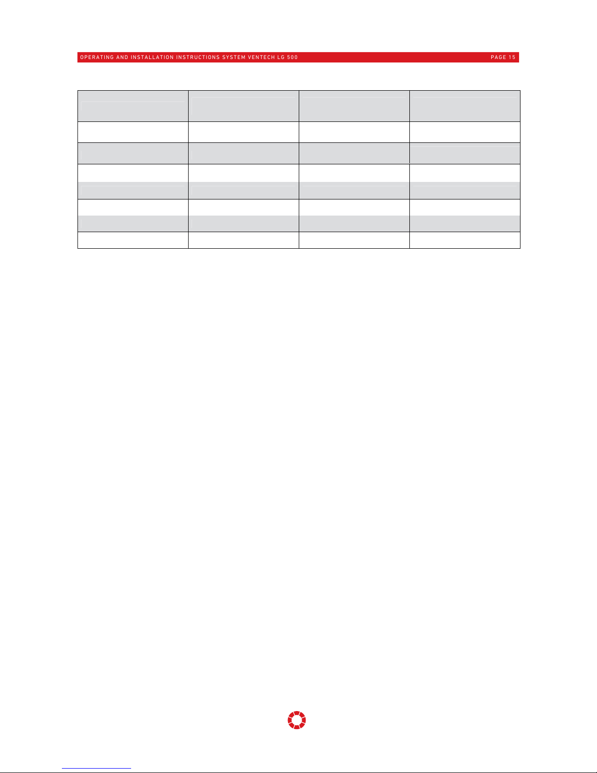
Fan speed CO2 in ppm Relative humidity in %
0 < 400 < 25
1 401 - 600 26 - 35
2 601 - 900 36 - 50
3 901 - 1500 51 - 65
on request
4 > 1500 > 65
4.4 Ventilation unit
4.4.1 Description
The compact ventilation unit LG 500 System VENTECH is used for the controlled mechanical ventilation of
houses, larger residential units, offices, surgeries and similar applications. The range of use extends
fundamentally to residential areas of 150 m² up to approx. 400 m², with an
adjustable air volume flow up to 550 m³/h.
The compact ventilation unit LG 500 System VENTECH, consists of a compact,
heat bridge-free and heat-insulated housing made from zinc-plated steel plate,
powder-coated exterior in RAL 9010, a highly efficient heat recovery system
with air/air counterflow heat exchanger made from recyclable plastic with an
efficiency level of approximately 92 %, an automatic 100 % bypass with energysaving radial fans in direct-current technology and EC technology with optional
constant flow volume regulation, air filters in quality category F7 in the supply
air and G4 in the extract air with integrated, wired, control electronics and an
optional "KOMFORT-G" remote control panel, for free-standing or wall mounting
in frost-free rooms.
4.4.2 Advantages and features
• With PHI passive house certificate and CH energy cluster declarati
on
• Ventilation unit with highly
efficient energy recovery
• Supply air an
d extr
act air fans with energy-saving EC motors
• 4-stage fan operation without constant volume flow function
• Optional with constant pressure control or electronic volume flow control for
constant air volume flow, adjustable up to 550 m³/h.
• Even with changes in the system pressure is the programmed air volume flow
maintained, for example, if the filter is dirty.
• Needs-based air volume control via CO2 sensor
• User-friendly "
KOMFORT-G
" control unit with integrated room temperature sensor
• Integrated 100 % bypass for bypassing the heat exchanger in summer mode
• Selectable, automatically operating frost protection switch for the heat exchanger,
optionally available with a PTC low temperature preheater battery
• Filter monitoring integrated, upon attainment of the time interval message ‘Filter
change’ appears on the display.
• Simple filter change without tools
• Optional reheater battery for additional raising of the room temperature
OPERATING AND INSTALLATION INSTRUCTIONS SYSTEM VENTECH LG 500
PAGE 15
0 - 2000 / 0 - 100
on request
on request
on request
on request
CO2 in ppm /
Relative humidity in %
1
2
2
Measuring sensor

4.4.3 Layout of the unit
1. Operator control unit type ‘
KOMFORT-G
’
2. Power unit
3. Connecting lead Y(ST)Y2x2x0.64
4. Outdoor air filter of quality class F7
5. Extract air filter of quality class G4
6. Counterflow heat exchanger
7. Condensate tank with discharge fitting
8. Frost protection heating with a PTC low temperature
preheater battery (optional)
9. Bypass valve with actuator
10. Outdoor air and supply air fan
11. Exhaust air and extract air fan
12. Pressure sensor for volume flow constant function (optional)
13. Exhaust-air-side sound absorber insert (optional)
14. Front cover with a knurled screw fastener
15. Air line connection
16. Cable leadthroughs
1. Operator control unit type ‘
KOMFORT-G
’
The "
KOMFORT-G
" control unit fitted directly in the living area is used to make settings for the ventilation unit.
The current operational statuses and system values, e.g. operating mode, fan speed, temperatures, etc., are
shown on the four-digit display. Operation (green), faults and filter change (flashing red) are displayed by way
of signal lamps. Automatic or manual mode can be selected. In automatic mode the system operates fully
automatically in accordance with programmable time programs, while in manual mode the fan speed, for
example, can be increased individually (air blast ventilation). The "
KOMFORT-G
" control unit can also be used
to make individual operating parameter settings during servicing work.
2. Power unit
The individual operating parameters are set by the skilled installer or service technician, matched to the
relevant application on site, via the power unit installed in the ventilation unit. The settings can be made either
via the "
KOMFORT-G
" control unit or via the PC interface and communication software.
3. Connecting lead Y(ST)Y2x2x0.64 (not included in the scope of supply)
A screened cable Y(ST)Y2x2x0.64 is required for communication between the operator control unit and the
power unit. The connecting cable is not included in the scope of supply. The cable length must not be longer
than 100 m. The plug connection to the power unit and to the operator control unit is by means of an IDE
connector.
4. Outdoor air filter of quality class F7
(
optional pollen filter of quality class F9)
The outdoor air filter removes dust and contamination from the outdoor air.
2
6
5
4
7
8
12
14
9
10
11
15
16 13
1
OPERATING AND INSTALLATION INSTRUCTIONS SYSTEM VENTECH LG 500
PAGE 16

5. Extract air filter of quality class G4 (optional F5)
Coarse contamination is filtered out of the extract air via the extract air filter.
6. Counterflow heat exchanger
The highly-efficient heat exchanger removes the energy content from the extract air and transfers this into
the supply air.
7. Condensate tank with discharge fitting
Any condensate incurred in the heat exchanger during operation is collected via the condensate trough. The
condensate incurred is discharged via the connected condensate drainage system, which is routed via an
effective odour trap.
8. Frost protection heating with a PTC low temperature preheater battery (optional)
In very cold outdoor air temperatures, protects against freezing of condensate in the heat exchanger. The
outdoor air is pre-heated, depending on the outdoor air temperature, via the optional electrical PTC lowtemperature pre-heater battery.
If a water battery or brine battery is used for frost protection the heat exchanger, the battery has to
be protected in a suitable way against freezing when there is frost.
9. Bypass valve with actuator
In summer mode, enables the bypassing of the air flow to the heat exchanger, provided that the outdoor air
temperature is lower than the room temperature.
10. Outdoor air and supply air fan
Ensures the air volume flow for the supply air; provides the living spaces with conditioned outdoor air.
11. Exhaust air and extract air fan
Ensures the air volume flow for the extract air; conveys the consumed air externally out of the apartment.
12. Pressure sensor for volume flow constant function (optional)
Measured value sensor and pressure sensors for the optional definable volume flow constant function of the
fans.
13. Exhaust-air-side sound absorber insert (optional)
For noise reduction in the vicinity of the exhaust air fan.
14. Front cover with a knurled screw fastener
The front cover can be easily opened for maintenance work to the device, e.g. filter exchange. When closing it,
make sure of complete fastening and sufficient seal tightness between the front cover and the unit’s housing.
15. Air line connection
Is for the purpose of connection to the air line system. When installing, ensure correct connection to the
supply, extract, outdoor air and exhaust air lines.
16. Cable leadthroughs
Fundamentally the ventilation unit is supplied electrically ready wired. The cable leadthroughs are used for
making the electrical connection, for connecting the operator control unit and the optional system
accessories, for example, temperature sensors etc.
OPERATING AND INSTALLATION INSTRUCTIONS SYSTEM VENTECH LG 500
PAGE 17

4.4.4 Versions
The compact ventilation unit LG 500 System VENTECH is available in several different versions:
right-hand or left-hand, depending on the location of the supply air connecting piece,
with or without electrical PTC pre-heater battery integrated into the ventilation unit for frost
protection of the heat exchanger
the device may also be optionally equipped with the following additional functions:
pressure sensor technology for volume flow or pressure constant function
exhaust-air-side sound absorber insert
needs-based ventilation operation via CO
2
sensor
Version Right-hand version Left-hand version
Part no. wit
hout
integrated PTC preheater battery
08LG500-R 08LG500-L
Item no. with an
integrated PTC
preheater battery
08LG500-RV 08LG500-LV
For standing or
wall-mounted
installation
4.4.5 Dimensions
Illustration with optional PTC low-temperature pre-heater battery, sound absorption unit for exhaust air side
and pressure sensor for extract air and supply air.
1 Supply air dia. 200 mm
2 Extract air dia. 200 mm
3 Outdoor air dia. 200 mm
4 Exhaust air dia. 200 mm
5 Counterflow heat
exchanger
6 Extract air fan
7 Supply air fan
8 Control unit
9 Extract air filter G4
10 Outdoor air filter F7
11 Condensate trough
12 Condensate connector ø 15 mm
13 Cable entry 6 x M16
14 PTC electrical preheater battery (optional)
15 Sound absorber insert for EHA
16 Height-adjustable feet
17 Supply air pressure sensor (optional)
18 Extract air pressure sensor (optional)
Illustration: LG 500-RV (right-hand version)
OPERATING AND INSTALLATION INSTRUCTIONS SYSTEM VENTECH LG 500
PAGE 18

Page 19 of 44
4.5 Safety devices
For the purpose of ensuring safe operation of the system the safety devices and covers must not be put out of
service, bypassed or dismantled by any measures.
The system must be shut down immediately if faults or malfunctions occur in the ventilation system that could
pose a risk to persons or property.
Further operation must be effectively prevented until a complete repair has been made! Repair may only be
performed by a skilled installer.
Overheating protection. A thermo bi-metal switch is built in to
protect the optionally-integrated frost protection heater battery
from overheating. When a temperature of +50 °C is reached, this
element interrupts the power supply to the PTC electric heater battery.
5 Technical specifications
5.1 Unit specifications
Ventilation unit
Dimensions (w x h x d) 915 x 855 x 655 mm
Housing of single-shell construction made of galvanized sheet
steel, coated in RAL 9010 – white Insulation 25 mm / 30 mm
Air line connection 4 x dia. 200 mm
Condensate connection dia. 15 mm at bottom
Voltage / frequency / current 230 V / 50 Hz / 16 A
Degree of protection IP 20
Permitted ambient temperature for unit 5 °C to +40 °C
permissible air temperatures -15 °C to +35 °C
Weight without accessories 75 kg
Operator control unit „
KOMFORT-G
"
Dimensions (w x h x d) 150 x 82 x 20 mm
Connecting cable to the power unit Cable Y(ST)Y2x2x0.64, screened, max. length < 100 m
Air filters
Outdoor air/supply air filter Pocket filters quality category F7, optional quality category F9
Extract air filter Pocket filters quality category G4
Fans (factory setting)
Fan speed Speed I Speed II Speed III Speed IV
Air volume flow [m³/h] 200 300 400 500
Output in [W] with external 50/100 Pa 50/65 80/100 130/155 210/235
Air volume flow setting range 150 to 550 m³/h, settable
in increments of 5 m³/h.
Flow efficiency in accordance with PHI 0.33 W/m³/h
Power consumption in standby mode 2.9 W
OPERATING AND INSTALLATION INSTRUCTIONS SYSTEM VENTECH LG 500
PAGE 19

Heat exchanger
Counterflow heat exchanger made of plastic
Degree of heat provision in accordance with
PHI 82 %
Comfort criterion in accordance with PHI T SAir= +16.5 Ԩ where T FAir= -10 °C
Degree of recovery in accordance with EN 308
(where extract air is 21 °C / 40 % RH)
Housing seal-tightness (according to PHI where nominal air volume flow is 366 m³/h)
external seal-tightness at 100 Pa < 0,6 %
external seal-tightness at 100 Pa < 0,5 %
5.2 Characteristic external pressure increase - air volume flow with volume flow constant
function
5.3 Characteristic external pressure increase - air volume flow without volume flow
constant function
The characteristics illustrated are applicable for the device
design with pressure sensor technology for volume flow
constant regulation, supply air filter quality category F7,
extract air filter quality category G4 and the design with PTC
pre-heater battery in bypass mode. The SFP values shown
take into account power consumption for both fans for supply
air and extract air as well as the power consumption of the
control unit.
The characteristics illustrated are applicable for the device
design with supply air filter quality category F7, extract air
filter quality category G4 and the design with PTC pre-heater
battery in bypass mode.
The SFP values shown take into account power consumption
for both fans for supply air and extract air as well as the power
consumption of the control unit.
OPERATING AND INSTALLATION INSTRUCTIONS SYSTEM VENTECH LG 500
PAGE 20

5.4 Acoustic specifications
Speed I = 200 m³/h / Speed II = 300 m³/h / Speed III = 400 m³/h / Speed IV = 500 m³/h
with external pressure increase of 100 Pa and integrated sound absorption splitter on the exhaust air side
Remark: Tolerances ± 2 dB for acoustic data
Measuring
point
Housing emission Outdoor air Supply air Exhaust air Extract air
Fan speed I II III IV I II III IV I II III IV I II III IV I II III IV
63 Hz
L
w
in dB
45 47 49 52 65 67 69 71 59 65 72 79 64 66 68 70 62 64 66 68
125 Hz 44 44 44 44 60 60 60 60 55 58 61 64 60 61 62 63 56 57 57 57
250 Hz 44 47 49 51 60 61 62 63 49 52 55 58 60 62 63 65 57 58 59 60
500 Hz 35 37 40 42 45 50 55 59 37 43 48 54 43 50 57 64 44 49 54 59
1000 Hz 31 32 33 34 31 35 39 44 25 31 37 43 31 36 41 47 30 35 39 44
2000 Hz 26 29 31 34 27 32 37 42 18 25 31 38 32 37 43 48 27 32 36 41
4000 Hz 24 28 31 34 21 26 32 37 14 20 26 32 30 35 40 46 16 21 26 32
8000 Hz 19 21 22 24 13 17 21 25 11 13 16 18 17 23 30 36 11 13 14 16
Total
LWA in dB(A)
39 41 44 45 53 55 57 59 44 48 53 57 53 55 60 63 50 51 55 58
6 Operator control unit
6.1 General information
The settings made on the ventilation unit are performed via an operator control unit. Control and operation of
the ventilation unit is performed via the "
KOMFORT-G"
control unit with an integrated room sensor for surface
mounting. The function buttons on the control panel make performing settings simple. All important operating
data are displayed. The signal lamps visualize the operating messages and fault messages.
The control unit is normally installed in the living area and should be suitably positioned. Thermal
source areas, radiators, direct sunlight etc. have to be avoided on account of their temperature
influence!
6.2 Control unit "
KOMFORT-G
"
The
KOMFORT-G
control unit impresses with its simple manipulation of all functions of the ventilation unit. All
status and fault messages in a text display are shown in plain text.
An integrated real-time clock enables automatic mode for clock-controlled adaptation of the fan speed and of
the temperature setpoint of the unit.
A battery is inset on the rear side of the operator control unit (type CR 2430 3V). If the supply voltage fails, the
system time is maintained by this. When the battery is empty the clock must be reset after any loss of power
to the ventilation unit - see Point 6.2.2.3 of these instructions.
OPERATING AND INSTALLATION INSTRUCTIONS SYSTEM VENTECH LG 500
PAGE 21
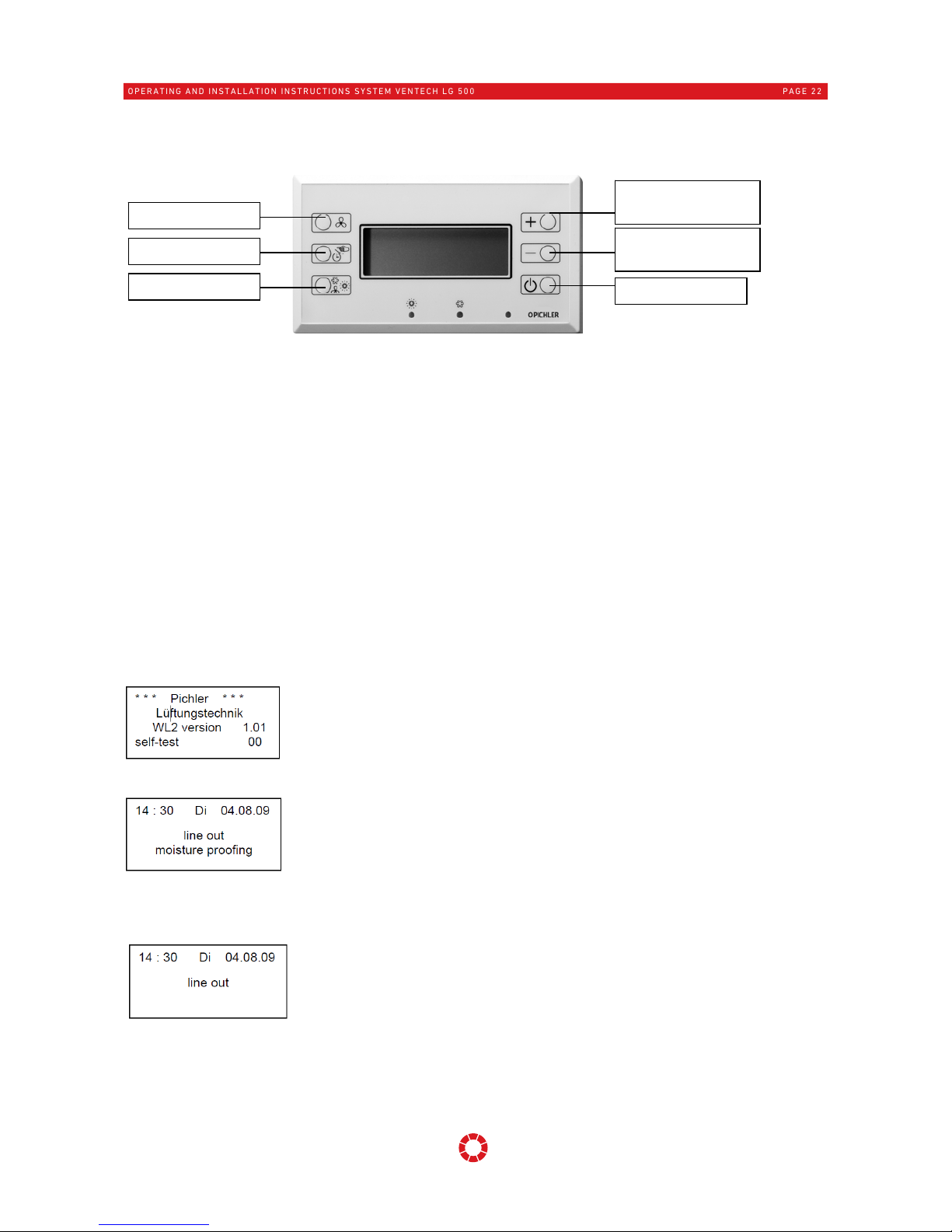
6.2.1 Buttons on the control unit "
KOMFORT-G
"
The "
KOMFORT-G
" control unit has 6 buttons.
The button at the bottom right switches the ventilation unit on or over to standby mode.
The two other buttons on the right-hand side are used to increase or decrease the temperature set value.
These buttons are also used in the configuration menu for setting other parameters.
The desired fan speed is set by means of the button at the top left. Pushing this button increases the fan
speed. If fan speed IV is exceeded, the setting returns to fan speed I.
The automatic button is located on the left-hand side in the centre. In automatic mode the fan speed and any
temperature reduction is determined with the aid of a timer. In manual mode, only the fan speed set by the
user is set, with no consideration of the time programme.
The lower left button switches between summer and winter operation.
6.2.2 Representation on the display
The operator control unit has a four-line display and three light emitting diodes for display purposes. The
display indicates the current status and any messages in clear text. The right-hand LED indicates whether the
system is in operation. When the device is in fault-free operation, this indicator lights green. If there is a fault,
the indicator flashes red. The two remaining LEDs indicate cooling or heating mode.
6.2.2.1 Starting the unit
Upon first voltage supply the operator control unit performs a self-test. This takes
10 seconds at the maximum and is shown on the display. The status last pending is
re-created when a restart take place after a voltage failure.
6.2.2.2 Switching the device on/off
The "
KOMFORT-G
" control unit has an On/Off button that switches the device into
standby mode when required.
In standby mode, depending on the configuration, the ventilation unit is either
completely deactivated or the fan speed is reduced to basic ventilation. When the
On/Off button is pressed the unit is switched back on and returns to its original status.
6.2.2.3 Setting the date and time
To set the time on the "
KOMFORT-G"
control unit, the device must be switched into
standby mode. In switched off condition the time can be edited by pressing the
automatic/manual button.
The present time display will then begin to flash. To change the displayed value,
the [+] and [-] buttons have to be pressed. Pressing the Automatic/Manual button
again will confirm the figure.
Once the correct hour is set and confirmed, the cursor will shift to the minute display. Repeat this process to
set the date and time. Once all figures are set, press the Automatic/Manual button again and the cursor will
disappear. The input can be terminated at any time by pressing the On/Off button.
on/standby
reducing temperature
set point
increasing temperature
set point
ventilation/heating
automatic/manual
fan step
OPERATING AND INSTALLATION INSTRUCTIONS SYSTEM VENTECH LG 500
PAGE 22

Temperatures
temperature set value 24 °C
room temperature 24 °C
outdoor temperature 14 °C
6.2.2.4 Automatic/Manual mode
The real-time clock integrated into the operator control unit enables automatic
mode. Optionally the fan speed can also be specified manually. Switch-over
between the two operating modes can be performed with the automatic/manual
button.
In automatic mode the fan speed is specified in accordance with a timer. In winter
mode, automatic mode also enables temperature reductions to be set for certain
times of day.
There is still manual mode as an alternative to automatic mode. In this mode, the
fan speed and the temperature set by the user are constantly maintained.
6.2.2.5 Summer mode/Winter mode
Switching between summer and winter mode in both manual and automatic mode enables change-over of the
earth heat exchanger (via the change-over value) and to control the brine pump.
In summer mode, the earth heat exchanger or brine pump will be activated when the outdoor temperature
(sensor AI9 required) reaches 20 °C (cooling function). In winter mode, the ground collector or brine pump will
be switched on when the outdoor temperature falls below 6 °C (outdoor air pre-heating).
In automatic mode, the device switches between summer and winter modes automatically with the time
changes in spring and autumn. In automatic mode no changeover from summer or winter mode is possible
manually. It is only possible to switch between these modes manually in manual mode. In addition, in
automatic mode, it is also possible to set separate switching times for summer and winter.
6.2.2.6 Bypass mode
Cooling mode:
If the outdoor air temperature is lower than the extract air temperature, and the extract air temperature is
2 °C (hysteresis) higher than the set temperature, the bypass valve bypasses the heat recovery to cool the
living area slightly (only a cooling effect!). The bypass valve function is only enabled when the outdoor air
temperature is a minimum of +14 °C.
Heating mode:
If the outdoor air temperature is higher than the extract air temperature, and the extract air temperature is
2°C lower than the set temperature, the bypass valve bypasses the heat recovery to blow the warm outdoor
air directly into the building and heat the living area.
6.2.2.7 Selecting the fan speed
In automatic mode, the current fan speed is selected via the set time
programme. However, there is the option to switch the ventilation unit to fan
speed IV. Fan speed IV is activated by pressing the fan speed button once. After
120 min (this time is adjustable), the control unit automatically switches back to
the fan speed preset by the time programme.
In manual mode the fan speed is prespecified only by hand. Pressing the fan speed key switches between fan
speed I, II, III and IV.
6.2.2.8 Setting the room temperature in conjunction with external auxiliary heating
Where ventilation units are installed in conjunction with additional external
heating, there is the facility to heat the supply air and, thus, regulate the
room temperature. The target temperature is adapted by pressing the
buttons [+] and [-] on the operator control unit’s operating display. When the
[+] or [-] button is pressed once, the current target temperature appears on
the display. The temperature set value can now be adjusted. The current room temperature and outdoor
temperature can also be viewed (outdoor temperature only with outside sensor AI9). If no buttons are pressed
for one minute, the new set value will be accepted and the control unit switches back to the display showing
the time.
OPERATING AND INSTALLATION INSTRUCTIONS SYSTEM VENTECH LG 500
PAGE 23

Service Menü
>Supply air
Extract air
Boost ventilation
Service Menü
>Offset T-Room
Basic ventilation
Filter
Service Menü
>Language setting
Regulation
6.2.2.9 Week time/Day time program
The integrated time programme has the facility to set the fan speed automatically, depending on the current
time and day. In the winter program a lowering mode for the air temperature can be set additionally on units
with external auxiliary heating.
The time programme has the facility to divide each day into three time intervals, for
each of which an individual fan speed can be set. The timer also differentiates
between weekdays, so that, for example, a different switching program can be set
for the weekend than that during the week. In addition, the time programme can
also differentiate between summer and winter modes. To adjust the day and time
programme as required, a special button combination is used to switch into the input mode for the time
programme.
Manual mode should be enabled. Hold down the Automatic/Manual button and press the On/Standby button.
The control unit then switches into the input mode for the time programme.
In the time programme menu, the Summer/Winter mode button is used to switch
between the time programmes for summer and winter. The time programme can
be processed by pressing the Automatic/Manual button. The [+] and [-] buttons are
used to alter the selected value. Further pressing of the automatic/manual button
causes the cursor to jump to the next entry.
If the switching program has been completed for one day (the cursor is on the fan speed for a time period c)
and if the cursor is moved further with the automatic/manual button, the day time program just created is
copied to the following day. The [+] button has to be confirmed for this.
To not adopt the values for the following day, the automatic/manual button has to be pressed, which moves
the cursor back to selection of the weekday again.
The time programme menu will automatically disappear if no button is pressed for one minute. The menu can
be quitted at any time by pressing the On/Standby button. The control unit will then return to the original
display and the settings are automatically accepted.
6.2.3 Special menu 1 – Operating hour counter (only for specialist installers)
The operator control unit has two special menus for the purpose of
performing basic configurations. Furthermore, additional information,
for example, the operating hours of the unit, can be read off in these
menus. This menu allows the operating hour counter to be read and
reset.
Special menu 1 can only be activated by a specialist. This menu displays the different runtimes of the
ventilation unit. Runtimes L1 to L4 show how many hours the device has operated for in each fan speed.
The operating hours of the basic ventilation are stored in L4 in this case. LG shows the total operating hours
for the ventilation unit.
H shows the operating hours for the pre-heating and B shows the total duration for which the bypass valve
has been activated.
Via RESET and pressing the minus button, the control unit is restored to factory settings.
To reset the operating hours, the cursor has to be activated by pressing the automatic/manual button. The
cursor appears in the total operating hours LG. All counters are set to the value 0 by pressing the [-] button.
6.2.4 Special menu 2 -
Language settings, basic ventilation, volume flows and fan speed IV
Special menu 2 is accessed via a combination of buttons. Manual mode has to be activated for this. Pressing
and holding the Summer/Winter button and simultaneously pressing the On/Standby button switches the
control unit to Special menu 2.
This menu enables the following settings to be made:
OPERATING AND INSTALLATION INSTRUCTIONS SYSTEM VENTECH LG 500
PAGE 24

Supply air
L1 = 140 m³/h
L2 = 250 m³/h
L3 = 400 m³/h
Supply air: LS1, LS2, LS3, volume flow set value for fan speed I, II und III (supply air side)
Extract air: LS1, LS2, LS3, volume flow set value for fan speed I, II und III (extract air side)
The air volume flow values can be set in increments of 5 m³/h. The maximum possible setting is 550 m³/h.
The air volume flow for fan speed IV can only be entered via the PC software (factory setting
500 m³/h). For volume flow constant regulation for the fans, the air volume flow is set directly in m³/h. For
operation without volume flow constant regulation (factory setting), the four fan speeds are set within a range
of 20 to 92 %.
For pressure constant regulation, the desired operating pressure is set from
50 Pa to 300 Pa. Basic settings regarding volume flow and pressure
constant regulation are made via the PC software (Point 7.1) to the power
section UZA.
Boost ventilation: This value represents the duration of fan speed IV in automatic mode and can be
set within a range of 5 min to 240 min using the [+] and [-] keys.
Offset T-Room: The indoor air temperature sensor on the control unit is calibrated.
Basic ventilation: When basic ventilation is enabled, the ventilation unit operates in standby mode at
the minimal fan speed (160 m³/h). When basic ventilation is disabled, the ventilation unit can be
switched off.
Filter: remaining filter run time (can be reset to filter load value 4600 h by simultaneously holding the
[+]/[-] buttons for 5 seconds)
Language setting: at this point the currently selected system language is displayed and can be set.
The languages German, English, Dutch and French are available for selection.
Regulation: when a re-heater battery is connected, it is possible to select between supply air
temperature regulation and room temperature regulation.
Sensor: Adjusting the sensor regulation: air quality (default setting) or humidity control.
As regards air quality, the regulation is performed according to the table and always follows the
highest measured value.
If humidity control is selected, the ventilation levels are only controlled according to the adjusted
values of the humidity sensor. This regulation option prevents the air in a ventilated room from drying
out.
7 Power unit
The controls consist of the power section UZA and the "
KOMFORT-G
" control unit. The power unit is connected
by means of a bus connection (length < 100 m; cable type Y(ST)Y2x2x0.64; screened) to the operator control
unit. Setpoints, actual values and error messages are interchanged between the operator control unit and the
power unit that is integrated into the unit via this bus connection.
7.1 Configuration and diagnosis via the PC software (only for specialist installers)
The power section UZA is defined via a PC connection using software. This is used, for instance, to enable the
function of an earth heat exchanger and heater battery. In addition to the configuration the software also
displays all current measured values.
Furthermore, the measured values and settings are marked and graphically displayed during operation.
7.1.1 Connecting the power section to a PC
A PC is connected to the power section UZA in the ventilation unit via a USB data cable.
OPERATING AND INSTALLATION INSTRUCTIONS SYSTEM VENTECH LG 500
PAGE 25

---- Notification ----
Replace the air filters
Filter
Remaining runtime
7.1.2 Software overview
The configuration software recognises a power section automatically. After it has completed its search, all
data and settings are read from the power section and appear on the programme's main screen.
The communication software enables all parameters to be adjusted and set. Detailed further information on
hardware, firmware and parameter descriptions etc. can be found in the separate document
"Leistungsbeschreibung für UZA Leistungsteil" (Specifications for UZA power section, available for specialist
installers only).
8 Messages/Faults
8.1 Operating messages on control unit "
KOMFORT-G
"
When the filter runtime has expired (factory setting 4600h), a command to
replace the air filters appears on the control unit.
8.1.1 Deletion of the filter message after a requested filter change
If the air filters in the ventilation unit have been changed, the filter counter is reset by simultaneously
pressing the [+] and [-] buttons for 5 seconds. Upon pressing this combination the filter message goes out.
8.1.2 Deletion of the filter message after a premature filter change
If the air filters are replaced prematurely, the filter counter has to be reset
without a pending filter message.
The filter counter is reset in Special menu 2 (see point 6.2.5) under
Filters "remaining runtime" by simultaneously pressing the [+] and [-] buttons for at least 5 seconds.
The factory setting for the filter timer is 4,600 hours (approx. ½ year).
OPERATING AND INSTALLATION INSTRUCTIONS SYSTEM VENTECH LG 500
PAGE 26
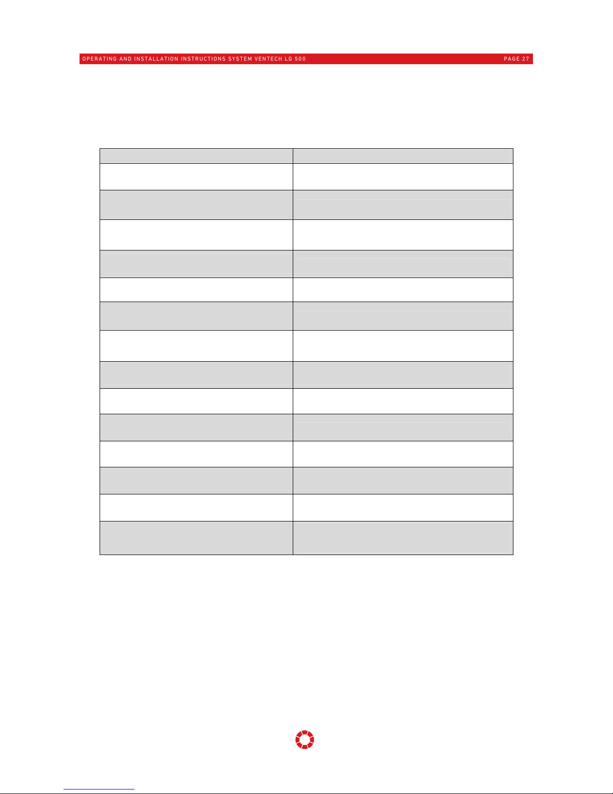
8.2 Malfunction messages on control unit "
KOMFORT-G
"
Fault states of the ventilation unit are indicated on the "
KOMFORT-G
" control unit via clear text messages. In
addition the operating light-emitting diode flashes red when in error status. The following error statuses are
displayed on the operator control unit:
Text display Description
Fan fault
No rotation speed
Fan shut down but set value in place.
Fan fault
Start-up
Fan shut down but set value in place.
Fan fault
Excess speed
Fan speed too high.
Fan fault
Ext. contact
External fault input - fan is active.
Fan fault
Ext. supply air contact
External fault input - supply air fan is active.
Fan fault
Ext. extract air contact
External fault input - extract air fan is active.
Communication fault
Data transfer
There is a communication problem between the operator
control unit and power unit.
Communication fault
Disconnection
There is a communication problem between the operator
control unit and power unit.
Measurement fault
Sensor 0-9 short circuit
The wire to a temperature sensor has a short circuit.
Measurement fault
Sensor 0-9 cable break
The wire to a temperature sensor has no resistance.
System fault
Parameter memory
Incorrect data in parameter memory.
External fault
Message active
An external fault is described. An input must be
configured as an external fault input.
Unknown fault
Fault number: …..
Unknown fault, can be evaluated by a specialist with a
fault number.
Frost shutdown
Temperature at supply air sensor AI3 or supply air sensor
RHB AI6 below 5 °C, or external input for frost protection
water heater battery active. Caution: risk of frost!!!
OPERATING AND INSTALLATION INSTRUCTIONS SYSTEM VENTECH LG 500
PAGE 27
9 Scope of delivery, transport, storage and disposal
9.1 Scope of supply
The scope of supply comprises the following:
the ventilation unit with "
KOMFORT-G
" control unit
the operating and installation instructions
the wall-mounting strap
optional accessories, such as PTC low-temperature pre-heater battery
When the device is delivered, check that the type number and serial number on the type plate correspond with
the information on the order and delivery documents, that the equipment is complete with any optional
accessories and that all parts have been delivered in defect-free condition.
N.B.: In the event of any transport damage and/or missing parts, this must be reported to the
forwarder or supplier immediately in writing.
9.2 Transport and Packaging
The ventilation unit LG 500 System VENTECH is delivered in transport packing.
The safety markings on the packaging must be observed.
Dimensions of the unit (w x h x d): 915 x 850 x 675 mm
Weight: approx. 75 kg without optional accessories
To prevent any damage caused by force during transport, the air compact venti
lation unit LG 500
System
VENTE
CH must be handled with care. Ensure that the device is not damaged by tipping or knocking over. The
unit must not be transported by the electrical connecting cable. Avoid knocks and blows when transporting.
The valid safety and accident regulations have to be complied with during transport. During manual transport
take care that only reasonable human lifting and carrying forces are used.
9.3 Storage
The device must be stored in the packaging in a suitable, dry, dust-free room and protected against frost.
Excessive storage periods, longer than a year, are to be avoided.
9.4 Waste disposal
Care has to be taken that the packing material and the protective packing are disposed of in an
environmentally friendly way. The packing materials have to be disposed of in accordance with the local
stipulations, for example, wooden pallets and cardboard packing have to be recycled. Air filters have to be
disposed of via the residual waste collection service.
Units that are no longer in working order have to be dismantled and properly disposed of by a
specialized company via suitable collection centres and in compliance with the waste electrical
and electronic equipment ordinance (WEEE), which provides for ratification of community law,
directive 202/95/EC (RoHS) and the directive 2002/96/EC (the WEEE directive).
OPERATING AND INSTALLATION INSTRUCTIONS SYSTEM VENTECH LG 500
PAGE 28

10 Installation
10.1 Prerequisites for installation of the unit
The compact ventilation unit LG 500 System VENTECH is to
be installed in accordance with general and loc
ally
applicable safety and installation regulations and in
accordance with the provisions of these operating
instructions.
The erection and installation work may be performed only
by authorized skilled personnel.
The ventilation unit must only be set up in a frost-free room,
e.g. in a cellar or loft, with ambient temperatures of a
minimum of +5 °C and a maximum of +40 °C. Accumulating
condensate water must be discharged frost-free and safely
via a gradient and using an effective drain trap (siphon).
The installation position for the device must be selected so
as to allow sufficient room to fit air line connections,
electrical connections and the condensate connection (6) as
well as to perform maintenance and inspection work.
In front of the unit a free space of at least 1 m has to be
taken into consideration for tending and servicing work. An e
ven and sufficiently hard installation surface
should be used for installing the ventilation unit. The ventilation unit can also be mounted on a solid wall,
capable of supporting the device weight, using the wall-mounting bracket (7) supplied as standard. In doing so
sufficient dimensioning (structural analysis) of the load-bearing components has to be ensured.
The following devices must be available in the installation room:
Air line connections for the supply, extract, outdoor air and exhaust air
An electrical mains connection of 230 V/50 Hz, fuse 16 A
Condensate drainage line with an effective odour trap
All on-site work (drainage, floor structure etc.) must be completed prior to installation of the ventilation unit.
After connection of the air lines to the ventilation unit, the unit is fixed and can no longer be moved.
The outdoor air and exhaust air lines, for example, between the ventilation unit and roof leadthrough, have to
be sufficiently insulated for energy reasons and for the purpose of avoiding condensate formation. No
condensate must be allowed to form on the air lines or in the roofing. In the case of line routes outside of the
thermally insulated building shell these routes have to be sufficiently insulated in the cold area.
To ensure proper and functional system operation, suitable insulation,
sound insulation and installation materials, conforming to the planning
documents and technical data, such as adequate sized sound absorbers,
supply air and extract air valves, overflow openings etc. should be
provided for. In principle, all device connection pieces should be fitted
with sound absorbers to ensure an appropriate sound level in the living
area.
Air line leadthroughs through walls or ceilings have to be made so that
they do not resonate due to structure-borne noise. To protect against
coarse contamination, for example, leaves, insects etc., a fine mesh wire
grating has to be provided as a prefilter directly at the central outdoor
air intake point. The protective grating has to be checked and, if
necessary, cleaned at regular intervals, in particular in the spring and
autumn. Inspection openings should be provided in the air line system to
facilitate cleaning and maintenance of the system.
OPERATING AND INSTALLATION INSTRUCTIONS SYSTEM VENTECH LG 500
PAGE 29

10.2 Device installation
For all work the safety instructions cited in point 3.2 of these instructions have to be heeded!
10.2.1 Setting up the ventilation unit - free-standing installation
The ventilation unit is supplied ready to operate and ready to plug in. Ensure
that there is sufficient room to fit air line connections, electrical connections
and the condensate connection as well as to perform maintenance and
inspection work.
After setting down the ventilation unit at the place of installation, it has to be
aligned in position. The ventilation unit must be installed horizontally and
securely. Alignment of the unit is possible easily via the adjustable feet of the
unit.
Ensure that there is sufficient distance between the underside of the device and the floor to
guarantee fault-free function of the condensate discharge.
10.2.2 Wall mounting
When mounting the ventilation unit on a wall, screw the four rubber buffers (1) out of the bottom of the device
and screw these into the housing rear (2) (four rubber buffers are supplied as standard).
The wall-mounting bracket (3) supplied as standard
should be fixed horizontally, to a suitable solid wall
capable of supporting the device weight. The weight of
the ventilation unit without optional accessories is 75 kg.
After installation of the wall mounting rail the ventilation unit’s two top
rubber buffers are hooked into the wall-mounting strap (3). When doing
this it must be ensured that the rubber buffers engage properly into the
recesses provided for this purpose. The device is aligned vertically
using the rubber buffers screwed into the underside of the housing
rear.
10.2.3 Production of the condensate water connection
The front door of the unit has to be opened to make the condensate drainage connection. A sufficiently long
hose with min. ø 15 mm internal cross section is connected to the condensate connector of the ventilation unit.
The loose end of the condensate hose is fed into a siphon which has been installed on-site. The odour trap can
also be made optionally with an effective water column of approx. 80 mm by bending the hose. The hose must
not be kinked and should be suitably fixed.
For reliable drainage of the water, a sufficient gradient (min. 5 %) must be ensured. The odour trap must be
filled with water to effectively prevent odour from spreading and for the avoidance of leaks. The condensate
tank should be filled with sufficient water to test the reliable drainage of water and the leak-tightness of all
connections before commissioning.
OPERATING AND INSTALLATION INSTRUCTIONS SYSTEM VENTECH LG 500
PAGE 30

Upon completion of the work all tools and installation materials have to be removed from the unit.
It has to be ensured that no tools or installation materials remain in the unit, because on initial
startup they can cause damage or the destruction of the unit.
When the front door is closed, sufficient and dependable sealing against the unit housing has to be ensured in
order to guarantee airtight and condensate-tight closure.
10.2.4 Connection of air lines and components
When connecting the air lines, ensure air-tightness and a suitable
vibrational decoupling.
The air lines and attachments, such as sound absorbers etc., must only
be fixed to the ventilation unit using adequately dimensioned fixing
elements and to suitable, solid walls or ceiling elements of the building.
The use of flexible hoses for making the unit connections has to be
avoided.
When making the line connections it has to be ensured in particular that
no tools and no installation materials fall into the unit connections or
onto the unit itself. Damage could then occur to the components, for
example, to the fans blades.
Suitable and sufficient insulation of the air line components and
installation components has to be made in accordance with the project
specifications.
10.3 Electrical connection
The electrical connection work and work on the electrical parts of the system may be performed only
by authorized skilled electricians in compliance with national and local regulations.
The relevant national and local regulations and standards must be complied with for the mounting
and electrical installation work.
The design of the ventilation unit complies with the safety requirements of the equipment and product safety
act and with the applicable stipulations of the EC directives.
The safety directions in point 3.2 and in particular in point 3.2.3. Electrical connection work have to be
complied with for all electrical work.
Condensate connection dia. 15 mm
Condensate cup with drainage
OPERATING AND INSTALLATION INSTRUCTIONS SYSTEM VENTECH LG 500
PAGE 31

10.3.1 Cable leadthroughs
When connecting the mains cable, connection cable for the "
KOMFORT-G
" control unit,
optional system components or external sensors, these should be fed into the
ventilation unit via the PG entry points on the top of the device.
10.3.2 Connection between the operator control unit and power unit
The controls consist of a power section and the
"KOMFORT-G"
control panel. The power section should be
connected to the control panel via a cable. The power unit can communicate the internal statuses and the
operating and fault messages to the operator control unit via this lead connection.
A screened cable Y(ST)Y2x2x0.64 is required to make the connection. The cable length must not be longer
than 100 m. The screening has to be clamped to the protective earth PE of the ventilation unit. The connection
cable is not supplied as standard.
The plug connection to the power unit and to the operator control unit is by means of an IDE connector.
10.3.3 Installation of the operator control unit
A suitable installation location has to be selected for the operator control unit, i.e. not in the vicinity of any
appliances with a temperature influence, not directly next to a window, not in places directly exposed to
sunlight and not behind or in furniture.
The "
KOMFORT-G
" control unit features an integrated temperature sensor that measures the
current room temperature.
The room temperature sensor is required for the control action of the control unit (optionally automatic
extract air, supply air or room temperature control). This function is described in the separate document
"Leistungsbeschreibung für UZA Leistungsteil" (Specifications for UZA power section).
10.3.3.1 Control unit "
KOMFORT-G
"
The "
KOMFORT-G
" control unit is mounted via the supplied electrical installation box by screwing the housing
frame into the prepared drill holes in the wall in which the connection cable has been laid. After plugging in
the connecting cable the operator control unit is fastened to the housing frame.
Mounting frame
Operator control unit
OPERATING AND INSTALLATION INSTRUCTIONS SYSTEM VENTECH LG 500
PAGE 32

10.3.4 Circuit diagram
The external system components, enhancement components and required temperature sensors
should be connected via the electrical connection diagram. Temperature sensors AI2 to AI5 are
factory wired. Outdoor temperature sensor AI9 and temperature sensor RHB AI6 are automatically
recognised and enabled by the controls.
Front board (top connections) LG 500
The functions marked as „options“ have to be activated via the
PC-software!
OPERATING AND INSTALLATION INSTRUCTIONS SYSTEM VENTECH LG 500
PAGE 33

Mainboard Bottom connections LG 500
The functions marked as „options“ have to be activated via the PC-software!
OPERATING AND INSTALLATION INSTRUCTIONS SYSTEM VENTECH LG 500
PAGE 34

Possible configuration of the in- and outputs
OPERATING AND INSTALLATION INSTRUCTIONS SYSTEM VENTECH LG 500
PAGE 35

Defined external potential-free digital inputs:
Automatic mode when input "E" is closed, the device switches into automatic mode. No other operating mode
can be enabled while the contact remains closed. When the contact is opened, the d
evice remains in automatic
mode and does not return to the original state.
Fan speed 4 when input "E1" is closed, fan speed 4 is enabled. The display shows "Ext. fan speed 4". When the
contact is opened, the device returns to its original state. Frost protection water heater battery
(see Point 4.2.4)
Fireplace mode - for operation in buildings with open fireplaces (see Point 2.1.2) when input "E3" is
closed, the device shuts down immediately and cannot be switched on in this operating mode. The display
shows Fireplace mode. When the contact is opened, the device returns to its original state.
Parameterised external digital outputs:
Malfunction message whenever a malfunction or warning message is displayed, the potential-free output
"K0" is closed. This enables faults to the device in external locations to be displayed.
Brine pump/Change-over valve 230V output "K8" (see Point 4.2.1 and 4.2.2)
10.3.5 Mains connection and replacement of the unit’s internal fuse
The ventilation unit LG 500 System VENTECH is supplied ready to plug in and may only be operated
at the voltage rating of 230 V/50 Hz, as specified on the type plate. Before performing work on the
electrical power section, the device must be disconnected from the mains and protected against
switching back on.
After unscrewing the protective cover for the electrical power section, the mains connection and electrical
pre-fuse can be accessed.
Unit’s internal fuse: Glass fuse 16 A dia. 6.3 x 32 mm, time-lag
Wiring diagram Ventilation unit LG 500 System VENTECH:
Fuse T16A
6.3 x 32 mm
OPERATING AND INSTALLATION INSTRUCTIONS SYSTEM VENTECH LG 500
PAGE 36

10.3.6 Connecting a water re-heater battery
When connecting an external water re-heater battery, an additional temperature sensor must be connected to
input AI6. The external supply air filter, available as an optional accessory, with a cable length of 5 m, part
No.: 40LG040370 is installed downstream of the re-heater battery in the air line. Sensor AI6 is automatically
recognised and enabled by the software. When the supply air falls below 5 °C at sensor AI6 (supply air sensor
RHB), a malfunction message is displayed, the fans shut down, the mixer opens and the circulation pump is
switched on (frost protection switching, re-heater battery).
10.4 Initial startup
The complete ventilation system must be in place along with all electrical, hydraulic and air-related
connections before commissioning the ventilation unit. Commissioning or system settings can only
be performed once all work to the system is complete.
The factory settings on the control unit may only be changed by a skilled installer. Incorrect settings can lead
to errors in the device!
factory settings of fan speed:
Fan
speed
Operating mode Designation
Volume
flow
I Basic ventilation Reduced ventilation mode with ventilation of the occupied area 200 m³/h
II
Normal
ventilation I
Fan speed enabled when no other fan speed is selected
manually or automatically
300 m³/h
III
Normal
ventilation II
Fan speed enabled when no other fan speed is selected
manually or automatically
400 m³/h
IV
Intensive
ventilation
Operation with increased volume flow, boost ventilation for
short, blast ventilation of the occupied area
500 m³/h
Basic procedure for initial startup:
Checking prior to initial startup
Are all air lines and integrated components installed?
Are all system components installed and electrically connected?
Is the electrical wiring complete and the operator control unit installed?
Is a functioning condensate connection established?
Are the air outlets, and inlet and outlet valves correctly fitted and in the open position?
Are the air filters in the ventilation unit correctly installed and in a clean condition?
Are the air filters in the earth heat exchanger etc. correctly installed and in a clean condition?
Are any installed fire dampers in the open position?
Setting the system parameters
Check system components and correct settings where necessary
Set system parameters, e.g. adjust air volume flow / fan speed
System time
Set time programme as required
OPERATING AND INSTALLATION INSTRUCTIONS SYSTEM VENTECH LG 500
PAGE 37

11 Servicing and cleaning
11.1 Safety directions
During cleaning and maintenance work to the ventilation unit, the mains plug should always be
removed or the ventilation unit disconnected from the mains at all poles!
Other available equipment components and system elements, e.g. earth heat exchanger, preheater and
reheater batteries, silencers etc. have to be serviced and cleaned in accordance with the regulations and
instructions.
When the front panel or the covers are opened and unscrewed, work has to be performed with great care,
conscious of safety and dangers.
A vacuum cleaner has to be used to remove the dirt and dust. Cleaning with great force or with compressed
air can cause damage to the components and to the surfaces. The use of corrosive or dissolving cleaning
agents is not permitted. The electrical components must not come into contact with moisture or wetness.
For all electrical work, observe the Safety instructions under Point 3.2 and in particular Point 3.2.3. for
electrical connection work.
11.2 Customer service
For all questions pertaining to the supplied Compact ventilation unit LG 500 System VENTECH please
contact the installer of your air treatment system or contact us directly.
11.3 Service instructions for the user
These instructions relate exclusively to the regular inspection, maintenance and replacement of air
filters by the user.
11.3.1 Air filters
The condition of the air filters has to be checked at regular intervals. If the filters are heavily contaminated,
these should be immediately replaced. Otherwise filters should be replaced depending on outdoor air
contamination in intervals of at least six months.
Only original replacement filters may be used and the permitted filter quality category should be observed.
The ventilation unit must never be operated without air filters for the supply air and extract air!
If ventilation units are shut down for long periods, air filters should be replaced before starting up again for
hygienic reasons!
Before removing air filters from the device, the filter tenter frames should be loosened by pulling forwards.
Only then can the air filters be gently lifted out and replaced.
Supply air filter fine dust filter
Quality category F7;
optional F9 as pollen filter
Extract air filter coarse dust filter
quality class G4
OPERATING AND INSTALLATION INSTRUCTIONS SYSTEM VENTECH LG 500
PAGE 38

When inserting the new filters care has to be taken that there is dependable sealing and sufficient clamping
between the air filter and filter tensioning frame to avoid high filter bypass leakages.
When replacing the air filters care has to be taken that no contamination of the unit or of the
system parts takes place. Contaminated filters are to be disposed of properly. It is advisable to
pack the air filter in an air-tight container immediately after removal from the device to avoid
contamination of the ventilation system and device.
11.4 Service instructions for the specialized installing company
The work tasks on the ventilation unit as specified below must be performed by skilled personnel
only. If defects are discovered during the course of maintenance work, these must be immediately
rectified to ensure a safe system operation. Only genuine spare parts may be used for
replacements or repairs.
11.4.1 Heat exchanger with bypass flap
Cleaning at least once annually is recommended, depending on the degree of
contamination of the heat exchanger.
The heat exchanger must be carefully removed from the device for
maintenance. The heat exchanger is cleaned by rinsing with warm water (max.
50 °C) and a normal cleaning agent and then rinsing off with warm water. Under
no circumstances should the exchanger be blown through with compressed air.
This could destroy the exchanger!
Before fitting the exchanger in the device, the guide rails of the exchanger
should be lightly greased to ensure simple and smooth sliding. The exchanger
should be replaced in the same position (extract air side should be returned to
the extract air side).
11.4.2 Fans
Before commencing work on the fans, power to the device unit must be disconnected and the device
secured against being switched on again! Maintenance and cleaning work on the fan is limited
exclusively to the fan housing and the impeller. Cleaning may be required depending on the degree
of the contamination of the fans.
Opening of the motor housing and working on the electrical components in the motor must be
performed only by the manufacturer of the fan. In the event of fan defects, this should be replaced
with a new original fan.
Filter tensioning frames
Air filters
OPERATING AND INSTALLATION INSTRUCTIONS SYSTEM VENTECH LG 500
PAGE 39

To clean the fans, the 4 fixing screws on the fan housing should be removed. The
fan has to be carefully pulled out of the housing. Attention has to be paid to the
electrical connecting cable to the motor. It must not incur any damage.
A soft brush has to be used to clean the fan blades. The fan housing is cleaned
with a vacuum cleaner.
Damage to the rotating blades must be avoided. Any balancing weights present
must not be removed or damaged, otherwise imbalance of the impeller will take
place in operation and an increased noise level and vibrations can occur as a
result.
11.4.3 Electrical PTC preheater battery (optional)
Depending on the degree of contamination of the heat unit, cleaning is
recommended at least annually.
Prior to working on electrical heater batteries, all poles of the
ventilation unit have to be switched to voltage-free and secured against
being switched back on!
The fins on the battery must not incur any damage in the course of the cleaning
work. A vacuum cleaner or soft brush should be used to remove dust.
During cleaning work to external electrical pre-heater batteries, the supply air
should always be inspected, where present, and replaced if contaminated.
11.4.4 Unit’s housing - internal cleaning
Depending on the degree of contamination, we recommend at least an
annual cleaning for the inside of the device housing.
During cleaning, ensure careful handling of the insulated surfaces of the
housing. Excessive use of force during cleaning, for example, when wiping
or brushing, can cause damage to the insulation surfaces! A vacuum
cleaner has to be used to remove the dust.
The electrical components must not come into contact with moisture or
wetness. In particular, attention has to be paid to avoiding possible damage
to the temperature sensors and electrical connecting lines.
11.4.5 Condensate drainage
Depending on the degree of contamination and temperatures, we recommend at least an annual cleaning of
the condensate discharge, the discharge line and the drain trap (siphon).
For reliable operation of the system, fault-free functioning of the condensate discharge line and its
components must be ensured. This functioning should be checked at regular intervals.
Any deposits or blockages in the drainage line and in the odour trap
have to be removed. The condensate cup has to be cleaned with a damp
cleaning cloth.
Test the functioning of the condensate drain with water after cleaning to
make sure it works properly. To do this, fill the condensate tray with
sufficient water. Then observe whether this water can drain reliably via
the condensate drain line into the discharge. Also check for leak
tightness.
To effectively counteract any odour nuisance or leakages, the odour
trap has to be filled with water prior to switching the system back on
Condensate tank
Condensate drain
OPERATING AND INSTALLATION INSTRUCTIONS SYSTEM VENTECH LG 500
PAGE 40

11.4.6 Service table
For the purpose of documenting the service work this table has to be filled in after performance of any work
on the system:
System installed by: Date
Item Service work (e.g. filter change)
Performed by:
Signature
Date
1
2
3
4
5
6
7
8
9
10
11
12
13
14
15
16
17
18
19
20
21
22
23
24
25
26
OPERATING AND INSTALLATION INSTRUCTIONS SYSTEM VENTECH LG 500
PAGE 41

12 Spare parts and accessories
Only genuine spare parts may be installed and used for replacement work and repairs. Dependable
operation is ensured only if genuine spare parts are used!
12.1 Control elements
Designation Item number
Control unit "
KOMFORT-G
" 08KOMFORTG
Screened connecting cable Y(ST)Y2x2x0.64 40LG040340
Outdoor temperature sensor for external applications 40LG040050
Glass time-lag fuse 16 A dia. 6.3 x 32 mm 40LG040500
Battery for control unit "
KOMFORT-G
" 40LG040060
External temperature sensor KTY8110, length 5 m 40LG040370
CO2 sensor module with surface-mounted housing 08LGCOFÜHLER
12.2 System components
Designation Item number
Optional electrical PTC low-temperature pre-heater unit
with outdoor air filter drying and bypass
40LG250BG210
Water-re-heater battery model 200-2-2.5 08PWW500200
Differential pressure sensor technology for volume flow
constant regulation consisting of component
40LG500BG190 supply air and
40LG500BG200 extract air
08DIFDRUCKLG500
Differential pressure sensor technology for pressure
constant regulation (50 to 300 Pa) consisting of
component 40LGBGxx supply air and
40LGBGxx extract air
08DRUCKKONLG500
Exhaust-air-side sound absorber insert
40LG500BG140
12.3 Air filters
Designation Item number Dimensions
Supply air filter quality category F7-
pocket filter L = 350 mm
40LG050090 500 x 200 x 350 mm
Optional supply air filter quality category F9 pocket filter L = 350 mm
40LG050110 500 x 200 x 350 mm
Extract air filter quality category G4 -
pocket filter L = 250 mm
40LG050100 500 x 190 x 250 mm
Optional extract air filter quality category F5 pocket filter L = 250 mm
40LG050120 500 x 190 x 250 mm
13 Subject to c
hange
We constantly make every effort to mak
e technical im
provemen
ts to a
nd optimize our products and reserve
the right to change th
e design of the units or the technical specifications without prior notice.
OPERATING AND INSTALLATION INSTRUCTIONS SYSTEM VENTECH LG 500
PAGE 42
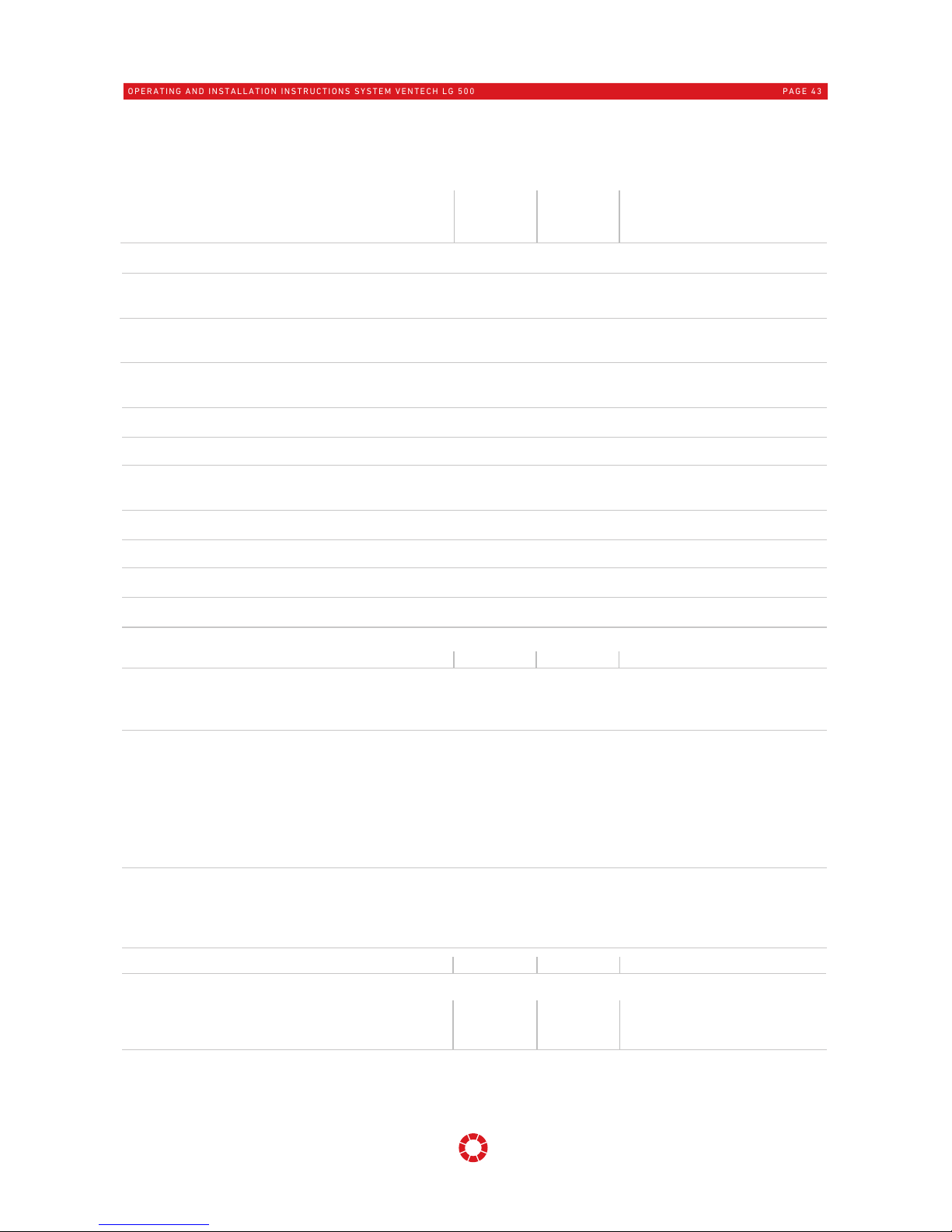
14 Product fiche
OPERATING AND INSTALLATION INSTRUCTIONS SYSTEM VENTECH LG 500
PAGE 43
Specific energy consumption (SEC)
cold climate
average climate
warm climate
Type
"residential ventilation system", "bidirectional ventilation system"
T
ype of heat recovery system
recuperative
Thermal efficiency of heat recovery
Maximum flow rate
Sound power level
Reference flow rate
Reference pressure difference
Specific power input
Electric power input of the fan drive, including any motor
control equipment, at maximum flow rate
Maximum air leakage rate
internal
external
Annual electricity consumption (AEC)
Annual heating saved (AHS)
cold climate
average climate
warm climate
Waste disposal
Units that are no longer in working order have to be dismantled and properly disposed of by a specialized company via
suitable collection centres and in compliance with the waste electrical and electronic equipment ordinance (WEEE), which
provides for ratification of community law, directive 202/95/EC (RoHS) and the directive 2002/96/EC (the WEEE directive).
η
t
Motor and drive
variable speed
Ventilation control (CTRL)
local demand control
q
Vd
P
E
q
Vn
p
tU
qvi / q
Vn
qve / q
Vn
Information based on the current state of knowledge of EU Regulations 1253/2014 and 1254/2014
Download from: www.pichlerluft.at
2 [-]
84,7% [-]
445 [m³/h]
173,0 [W]
L
WA
42 [dB(A) ]
50 [Pa]
0,255 [W/(m³/h)]
SPI
0,58% [-]
x-value
1,50% [-]
Filter change
The filters are to be replaced as soon as the command to replace the
filters appears on the display of the operator control unit (marked red in
the picture alongside).
CAUTION:
If the filters are not changed regularly, the system can not work efficiently
and the power consumption increases.
311,5 [m³/h]
manual control
clock control
central
demand control
local
demand control
[kWh/(m²·a)]
[kWh/(m²·a)]
-72,49
-35,68
-11,96
-73,75
-36,70
-12,85
-76,14
-38,63
-14,51
-80,45
-42,00
-17,35 [kWh/(m²·a)]
1 0,95 0,85
0,65 [-]
3,65 3,34 2,76 1,80
[kWh electricity/a]
86,31
86,79 87,75
89,66
44,12
44,37 44,85 45,83
19,95
20,06 20,28 20,72
[kWh primary energy/a]
[kWh primary energy/a]
[kWh
primary energy/a]
Operator control unit "KOMFORT-G"
- - -
r epor t - - -
Power unit
Exchange filter
Error no. =01
Specific energy consumption class
A+ (most efficient)
AAA

Hersteller/
Manufacturer:
Anschrift/
Address:
Bezeichnung/
Product description:
Aus
führungen
/
Versions:
J. Pichler Gesellschaft m.b.H.
Karlweg 5
9021 Klagenfurt am Wörthersee
Compact ventilation unit LG 500
System VENTECH with integrated control unit
LG500-R / LG500-L / LG500-RV / LG500-LV with
control unit type "
KOMFORT-G
"
Die bezeichneten Produkte stimmen in der von uns in Verkehr gebrachten Ausführung mit den Vorschriften folgender
europäischen Richtlinien überein:
The versions marketed by us of the products described above comply with the regulations of the following European
directives: EN 60335-1:2002 + A11:2004 + A1:2004 + A12:2006 + A2:2006 + A13:2008 + A14:2010; EN50366:2003 +
A1:2006; EN 62233:2008; EN55014-1:2006 + A1:2009; EN 55014-2:1997 + A1:2001 + A2:2008; EN61000-3-2:2006 +
A1:2009 + A2:2009; EN61000-3-3:2008
J. Pichler Gesellschaft m.b.H.
Klagenfurt, 08. August 2016
Geschäftsleitung / General manager
15 EG-Konformitätserklärung (EC Declaration of Conformity)
OPERATING AND INSTALLATION INSTRUCTIONS SYSTEM VENTECH LG 500
PAGE 44
2014/35/EU
2014/30/EG
Zur Harmonisierung der Rechtsvorschriften der Mitgliedsstaaten über die Bereitstellung elektrischer
Betriebsmittel zur Verwendung innerhalb bestimmter Spannungsgrenzen auf dem Markt
On the harmonisation of the laws of the Member States relating to the making available on the market of
electrical equipment designed for use within certain voltage limits
Zur Harmonisierung der Rechtsvorschriften der Mitgliedstaaten über die elektromagnetische
Verträglichkeit
On the harmonisation of the laws of the Member States relating to electromagnetic compatibility
2
009/125/EG Richtlinie des Europäischen Parlaments und des Rates zur Angleichung der Rechtsvorschriften der Mitglieds-
staaten zur Schaffung eines Rahmens für die Festlegung von Anforderungen an die umweltgerechte Gestaltung
energieverbrauchsrelevanter Produkte
Council Directive on the approximation of the laws of the Member States establishing a framework for the setting
of ecodesign requirements for energy-related products
Die Konformität mit den Richtlinien wird nachgewiesen durch die Einhaltung folgender Normen und Verordnungen:
Conformity to the Directives is assured through the application of the following standards and regulations:
VO 1253/2014/EU Verordnung (EU) der Kommission zur Durchführung der Richtlinie 2009/125/EG des Europäischen
Parlaments und des Rates hinsichtlich der Anforderungen an die umweltgerechte Gestalt
ung von Lüftungsanlagen
COMMISSION REGULATION (EU) implementing Directive 2009/125/EC of the European Parliament and of the Council with
regard to ecodesign requirements for ventilation units
VO 1254/2014/EU zur Ergänzung der Richtlinie 2010/30/EU des Europäischen Parlaments u
nd des Rates im Hinblick auf
die Kenn-zeichnung von Wohnraumlüftungsgeräten in Bezug auf den Energieverbrauch
VO 1254/2014/EU supplementing Directive 2010/30/EU of the European Parliament and of the Council with regard to energy
labelling of residential ventilation units
ÖVE / ÖNORM EN 60335-1
ÖVE / ÖNORM EN 60335-2-30 (analogously)
ÖVE / ÖNORM EN 60335-2-65 (analogously)
ÖVE / ÖNORM EN 60335-2-80 (analogously)
ÖVE / ÖNORM EN 50366
ÖVE /
ÖNORM EN 62233
ÖVE / ÖNORM EN 55014-1
ÖVE / ÖNORM EN 55014-2
ÖVE / ÖNORM EN 61000-3-2
ÖVE / ÖNORM EN 61000-3-3
E
ine vom Lieferzustand abweichende Veränderung des Gerätes führt zum Verlust der Konformität.
Product modifications after delivery may result in a loss of conformity.
Diese Erklärung bescheinigt die Übereinstimmung mit den genannten Richtlinien, ist jedoch keine Zusicherung von
Eigenschaften. Die Sicherheitsinformationen der mitgelieferten Produktdokumentation sind zu beachten.
This declaration certifies the conformity to the specified directives but contains no assurance of properties. The safety
documentation
accompanying the product shall be considered in detail.

Notes
OPERATING AND INSTALLATION INSTRUCTIONS SYSTEM VENTECH LG 500
PAGE 45

Notes
OPERATING AND INSTALLATION INSTRUCTIONS SYSTEM VENTECH LG 500
PAGE 46

Notes
OPERATING AND INSTALLATION INSTRUCTIONS SYSTEM VENTECH LG 500
PAGE 47

J. PICHLER
Gesellschaft m.b.H.
oce@pichlerluft.at
www.pichlerluft.at
ÖSTERREICH
9021 KLAGENFURT
AM WÖRTHERSEE
Karlweg 5
T +43 (0)463 32769
F +43 (0)463 37548
ÖSTERREICH
1100 WIEN
Doerenkampgasse 5
T +43 (0)1 6880988
F +43 (0)1 6880988-13
Sales oces in
Slovenia and Serbia.
Sales partners in
Germany, Switzerland
and Italy.
Your partner/installer:
OPERATING AND INSTALLATION INSTRUCTIONS SYSTEM VENTECH LG 500
PAGE 48
Responsible for the content: J. Pichler Gesellschaft m.b.H.
Photos: Ferdinand Neumüller, Archiv J. Pichler Gesellschaft m.b.H. | Text: J. Pichler Gesellschaft m.b.H.
All rights reserved | All photos are symbolic photos | Subject to change without notice | Version: 02/2017 db
Systematic ventilation.
ErP
20 18
ErP 2018
Fulfils the requirements of the Ecodesign Directive,
in accordance with EU Regulation 1253/2014.
IG
PASSIVHAUS
TIROL
 Loading...