


Operating and mounting
instructions
Air humidification unit
LBE 250/LBE 500
Systematic ventilation.
COMFORT
VENTILATION
OPERATING AND
MOUNTING INSTRUCTIONS
LBE 250 / LBE 500

Contents
1. Introduction ............................................................................................................................ 4
2. Intended use ............................................................................................................................ 4
5. Safety notices .......................................................................................................................... 6
6. Transport, storage and disposal ................................................................................................ 8
6.1 Dimensions and weight .......................................................................................................................... 8
6.2 Packaging ............................................................................................................................................... 8
6.3 Storage ...................................................................................................................................................
8
6.4 Check for completeness .......................................................................................................................... 8
6.5 Scope of supply ....................................................................................................................................... 8
7. Structure ................................................................................................................................. 9
8. Description of functions ......................................................................................................... 10
8.1 Working principle .................................................................................................................................. 10
8.2 Humidity control ...............................................................................................................................
.... 10
8.3 Temperature control
............................................................................................................................. 11
9. Control system ....................................................................................................................... 11
9.1 Operation/keypad/display .................................................................................................................... 11
9.2 Customer menu..................................................................................................................................... 12
9.3 Settings Temperature 21°C< ................................................................................................................ 12
10. Operational statuses .............................................................................................................. 13
10.1 Automatic activation/deactivation ....................................................................................................... 13
10.2 Automatic activation/deactivation (Auto STANDBY) ............................................................................ 13
10.3 Manual activation/deactivation (Manu STANDBY) .............................................................................. 13
10.4 Automatic activation/deactivation depending on air current ("Control Off") ...................................... 13
10.5 Rinsing .................................................................................................................................................. 14
10.6 Control on ............................................................................................................................................. 14
10.7 Fill .......................................................................................................................................................... 14
10.8 Water replacement ............................................................................................................................... 14
11. Error messages ...................................................................................................................... 14
11.1 Filter change! (customer) ...................................................................................................................... 14
11.2 UVC pip defective! (expert) .................................................................................................................. 14
11.3 Descaling! (expert) ................................................................................................................................ 14
11.4 Pump, outlet defective! (expert) ........................................................................................................... 15
11.5 Humidity too high! (expert) .................................................................................................................. 15
11.6 Humidity too low! (expert).................................................................................................................... 15
11.7 Service (expert) ..................................................................................................................................... 15
3.
Liability ................................................................................................................................... 5
4. Warranty ................................................................................................................................. 5
6.6 Waste disposal ........................................................................................................................................ 8

13. Commissioning ................................................................................................................... 16
14. Expert menu ...................................................................................................................... 18
14.1 Expert menu overview ............................................................................................................................... 18
14.2 Settings ...................................................................................................................................................... 19
15. Technical data .................................................................................................................... 24
16. Dimensions/design variants ............................................................................................... 25
16.1 LBE 250 ...................................................................................................................................................... 25
16.2 LBE 500 ...................................................................................................................................................... 26
17. Mounting ........................................................................................................................... 27
18. Connections/installation .................................................................................................... 28
18.1 Routing of air lines ..................................................................................................................................... 28
18.2 Waste water connection ............................................................................................................................ 28
18.3 Mains water connection ............................................................................................................................ 29
18.4 Water heater battery connection .............................................................................................................. 30
18.5 Hydraulic connection diagram (for version with warm water heater battery): ......................................... 30
18.6 Low temperature heating (only LBE 250!): ................................................................................................ 31
19. Wiring diagram .................................................................................................................. 32
20. Maintenance (expert) ........................................................................................................ 33
22. Subject to change without notice ....................................................................................... 35
23. EG-Konformitätserklärung ................................................................................................. 36
21. Spare parts and accessories ................................................................................................ 35
12. Maintenance (customer): "Filter Change" ......................................................................... 15

1. Introduction
Dear Customer,
Thank you for purchasing the LBE 250/LBE 500 air humidification unit.
The LBE 250/LBE 500 air humidification unit is available in two versions and corresponds to state-of-theart technology. It convinces through operating safety, operating comfort, and economic efficiency.
To operate your air humidification unit safely, properly, and economically, carefully read and observe
these operating instructions.
Use the air humidification unit only when it is in a perfect state in a proper, safety and risk conscious
manner under consideration of all information in these instructions.
If you have further questions, please contact us.
In case of inquiries and spare parts orders, please have the device
type and serial number (see the type plate on the device) on hand!
Please keep these operating instructions in a safe place that is
always accessible.
Please contact us in case of a loss of the documentation.
2. Intended use
The LBE 250/LBE 500 air humidification unit is intended for immediate or later installation into ventilation
and air conditioning systems with a maximum air volume flow of 250 m³/h (LBE 250) or 500 m³/h (LBE
500).
This device, which is accessible to the general public, is intended for installation in residential or
commercial buildings.
It is used for active indoor air humidification and can also be used for auxiliary heating.
The compact air humidification unit works according to the principle of natural evaporation and guarantees
constant, optimum indoor air humidity in living areas, adjustable in a range from 40% to 60 % relative
humidity.
In addition, a constant supply air temperature that can be adjusted within a range from 15°C to 25°C is
generated by an integrated air heater battery.
As a part of intended use, our required operating and mounting instructions must also be observed. Only
qualified, assigned personnel may work on and with the device. People who transport or work on the
device must have read and understood the corresponding parts of the operating instructions, especially
Chapter 3 "Safety Instructions."
In addition, the plant installer must inform the end user of any possible risks.
The LBE 250/LBE 500 air humidification unit is not a product that is ready for use. It may not be
commissioned until it has been properly installed into the ventilation and air conditioning system and
connected.
The air humidification unit is not suited for outdoor setup. It may only be used in suitable, temperaturecontrolled indoor rooms.
Subject to technical changes.
We are constantly performing technical improvements and optimisations on your products and reserves
the right to modify the devices or technical data without prior notice

The manufacturer shall accept no liability for any damages due to:
3. Liability
4. Warranty
The warranty begins with initial startup, at the latest, however, one month after delivery has taken place.
The warranty covers the pure replacement of materials only and does not include any claims for
the compensation of services. It applies only if there is proof of appropriately performed maintenance in
accordance with our regulations and by a licensed company that specializes in installation work.
The warranty right extends to a maximum term of 24 months after installation of the air humidification unit
LBE 250/500, however, up to a maximum of 30 months after the manufacturing date.
Warranty claims can be asserted only for material and/or design defects that have occurred during the
warranty term. In the event of a warranty claim the air humidification unit LBE 250/500 must not be
dismantled without the previous written authorization of the manufacturer. The manufacturer
accords a warranty on spare parts only if they have been installed by an installer who is recognized by the
manufacturer.
The warranty shall lapse automatically upon expiry of the warranty period, in the event of improper
operation, e.g. operation without a filter, if genuine parts supplied by the manufacturer are not installed, in
the event of non-authorizedchanges or modifications that have been performed on the air humidification
unit.
Failure to comply with these Operating and Installation Instructions will automatically void all warranties.

5. Safety notices
General information
The following safety symbols indicate text passages that warn against risks and sources of danger. Please
familiarise yourself with these symbols.
Caution!
The non-observance of this warning can lead to injury or danger to life and limb and/or damage
of the device.
Attention: dangerous electrical voltage!
The non-observance of this warning can lead to injury or danger to life and limb.
General safety notices
All safety and danger notices located on the device must be observed.
In case of malfunctions, shut down the device immediately and secure it against activation.
Malfunctions must be eliminated immediately.
After servicing work, have expert personnel re- establish the operating safety of the device. Use only
original spare parts. For the operation of the device, the national regulations also apply without limitation
Read these operating instructions carefully and follow the safety notices.
Damage arising from a non-observance of the operating and maintenance instructions is not covered by
the guarantee.
This device is not intended to be used by people (including children) with limited physical, sensory, or
mental capabilities or with a lack of experience and/or knowledge, unless supervised by a person who is
responsible for their safety or who instructs them in the use of the device. Make sure that children do
not play with the device.
Caution!
After commissioning, the current supply may not be interrupted for longer than one day so that
the hygienic requirements can be observed.
In case of an interruption in the electrical voltage supply of more than 24 hours, the air humidification unit
may become contaminated with germs. In this case, a general cleaning of all components should be
performed before the unit is commissioned. If necessary, components must be replaced.
Deactivation of the ventilation and air conditioning system
If the ventilation and air conditioning system is decommissioned for more than one day, the air
humidification unit must be shut down beforehand for at least two hours. In this way, the air humidification
unit can thus dry out and hygienically perfect function is guaranteed.
Working on the device
Mounting, commissioning, maintenance, and repairs must be performed by an authorized expert
(heating specialist firm/installation specialist firm).
When working on the device, de- energise it and secure it against reactivation. The water supply
must be shut off.
UVC disinfection pipes
A UVC pipe type Phillips TUV 16W 4P-SE is installed into the standard version of the device! It
may only be replaced by a type listed on the label of the device. UVC pipes may be changed only
by authorised expert personnel! Before the unit is opened or a UVC pipe is changed, the device absolutely
must be de-energised and the mains plug must be pulled. Never look directly into the lit UVC light
source without eye protection.
Device setup/installation
The device may be installed only in frost-free, dry rooms. The room temperature must lie between +5°C
and a maximum of +40°C.
Ventilation and air conditioning system air lines that are not installed in heated areas must be designed
with suitable heat insulation (danger when the dew point temperature is undershot) to prevent the
formation of condensation.
For components or windows with bad heat insulation properties, in case of missing construction, and in old
buildings, condensation may form on window glass at cold temperatures and in case of increased air

humidity in living areas. The surface temperature of the components must lie above the dew point
temperature of the indoor air (at least about +15°C).
In normal operation, germs or mould cannot form inside the device unit since the humidification water is
continuously treated and disinfected during operation.
Mounting
The device is intended for horizontal mounting. It may deviate a maximum of +/-1° from the horizontal
position and must be mounted to a massive wall that can bear the load. The intrinsic operating weight of
the air humidification unit must be taken into consideration for the suspension. No shocks or jolts may
affect the device. For mounting and setup, the national and local regulations must be observed. The
device may be installed only in compliance with the national installation regulations.
Electrical connection
The electrical connection of the supply and sensor line should be performed by an electrician
according to the local regulations. Before the device is opened, the voltage supply must be shut
off at all poles and secured against reactivation. If the mains connecting line of the device is damaged or
defective, it must be repaired or replaced immediately to prevent risks. This work may be performed only
by authorised expert personnel.
Water connections
The water, heating, and waste water connections must be established by an expert. For the connection to
the water supply, only the original connecting hoses provided in delivery may be used. Pay attention to the
seal tightness of the lines. The maximum water pressure of the mains water supply of 0.7 MPa and of the
water heater battery of 1 MPa may not be exceeded.
Water quality
Only mains water that corresponds with the local mains water ordinance may be used for the water supply.
The water inlet pipe to the air humidification unit should be established using optionally available
connection sets.
In case of a chlorine content over 0.1 mg/l, the standard water filter (5 μm) must be replaced by a dual
filter (5 μm/carbon). If the iron content of the mains water exceeds a value of 0.1 mg/l, an iron filter should
also be built into the water inlet pipe.
The device can be used for a maximum hardness of water of 26°dH. When this value is exceeded, the
service life of the reverse osmosis membrane is considerably reduced.
Operation of the device
Every working method that impairs the safety of the device is prohibited. All warning and safety devices
should be regularly checked for proper function. Safety devices may not be disassembled or
decommissioned.
Mounting, disassembly, maintenance, and servicing of the device
If maintenance work or repairs are performed, the device should be de-energised. The attachment or
installation of additional equipment is not permitted. In this case, please consult with the manufacturer.
Electrical system/electronics Work on the electrical plant parts may be performed only by
electricians. If maintenance work or repairs are performed, the device should be de-energised.
In case of faults in the electrical voltage supply, shut down the device immediately. Use only
original fuses with the required current strength. Check the electrical equipment of the device regularly.
Discovered defects like loose connections or scorched cables must be eliminated immediately. After the
electrical work or servicing has been performed, the safety measures should be tested (e.g. earthing
resistance).
Requirement on the installation site
The installation of the air humidification unit may take place only in rooms that have an existing water
outlet. In addition, safety measures that automatically close the water supply to the air humidification unit
in case of leakage (e.g. safety valve/water connection set) must be taken within the room. The air
humidification unit is designed in IP20 type of protection.

6. Transport and storage and disposal
To prevent damage during transport due to force, the air humidification unit must be handled carefully.
During transport by hand, reasonable human lifting and carrying forces must be observed.
Age Reasonable load in kg
Women Men
15 – 18 years 15 35
19 – 45 years 15 55
Over 45 years 15 45
The unit may not be transported by the connecting cable. Impacts and shocks should be avoided.
6.1 Dimensions and weight
Dimensions of the packing unit
LBE 250: Width: 800 mm, height: 460 mm, depth: 420 mm
LBE 500: Width: 870 mm, height: 600 mm, depth: 600 mm
Weight of the packing unit:
LBE 250 28 kg without optional accessories
LBE 500 62 kg without optional accessories
6.2 Packaging
The safety labels attached to the box absolutely must be observed. During delivery, look out for and check
any damage to the packaging or device. Problems or damage must be reported immediately.
6.3 Storage
The device must be stored in the packaging in a dry, dust-free, and frost-protected manner. Avoid storage
periods that are too long (recommendation: one year maximum).
6.4 Check for completeness
When the device is delivered, make sure:
The type and serial numbers on the type plate correspond with the information in the order and
delivery documents.
The equipment (optional accessories) is complete.
All parts are present in a perfect state.
Note: In case of any transport damage and/or missing parts, you must inform the transport company or
suppler immediately in writing.
6.5 Scope of supply
The delivery comprises the following:
• the air humidification unit
• the operating and mounting instructions
• accessories like: the water connection set (see Section 16.3)
• optional accessories like: the pumps/mixer connection set (see Section 16.4)
6.6 Waste Disposal
Care has to be taken that the packing material and the protective packing are disposed of in an
environmentally friendly way. The
packing materials have to be disposed of in accordance with the local
stipulations, for example, wooden pallets and cardboard packing have to be recycled.
Units that are no longer in working order have to be dismantled and properly disposed of by a
specialized company via suitable collection centres and in compliance with the waste electrical
and electronic equipment ordinance (WEEE), which provides for ratification of community law,
directive 202/95/EC (RoHS) and the directive 2002/96/EC (the WEEE directive).

7. Structure
1. Water tank
2. Motor
3. UVC pipe for disinfection
4. Sensor plate with a temperature and humidity sensor
5. Inlet valve
6. UVC pipe series connection unit
(LBE 250, 1 pc / LBE 500, 2 pcs)
7. Reverse osmosis membrane
8. Outlet pump
9. Electronic operation system
10. Main board
11. Bladed rotary evaporator
12. Warm water heater battery (air side)
8. Description of functions
8.1 Working principle
The air humidification unit works according to the principle of natural evaporation and guarantees a
constant relative air humidity that can be adjusted between 40% and 60% in the
supply air.
The unit works
automatically, and the air humidity is electronically monitored in the device. The indoor air can thus not be
overhumidified.
The air humidification unit is dimensioned for a maximum operating air volume flow of 250 m³/h (LBE 250)
/ 500 m³/h (LBE 500). The water tank is supplied with mains water from the mains water supply. According
to the evaporative power, a maximum of 2.5 litres of water, which is continuously placed, is located in the
tank.
The maximum filling level is limited using a floating switch and mechanical overflow. The water in the tank
is continuously disinfected using UVC light, whereby the UVC pipe illuminates the complete water tank and
evaporation surface. The UVC pipe has a radiant power of 4.3 watt at a wavelength of 253.7 nm. For
safety reasons, the UVC pipe is monitored by UV diode. This monitoring process can detect a failure,
soiling, or line breakage of the disinfection unit. If the radiant power is too low, the water is drained and a
error message is output. The unit is automatically shut down in case the UVC pipe malfunctions.
To prevent deposits during operation, especially scale deposits on the bladed rotary evaporator and the
water tank, the standard version of the air humidification unit is equipped with a reverse osmosis unit. In
the standard design, the reverse osmosis unit is integrated into the water inlet pipe between the solenoid
valve and the water tank.
A prefiltering unit for the water supply, which should be installed during the course of mounting, is included
in the scope of supply. As an additional safety measure, the water is drained and an error message output
in case of the air humidity is exceeded by more than 30% of the reference value of the water for longer tan
25 hours.
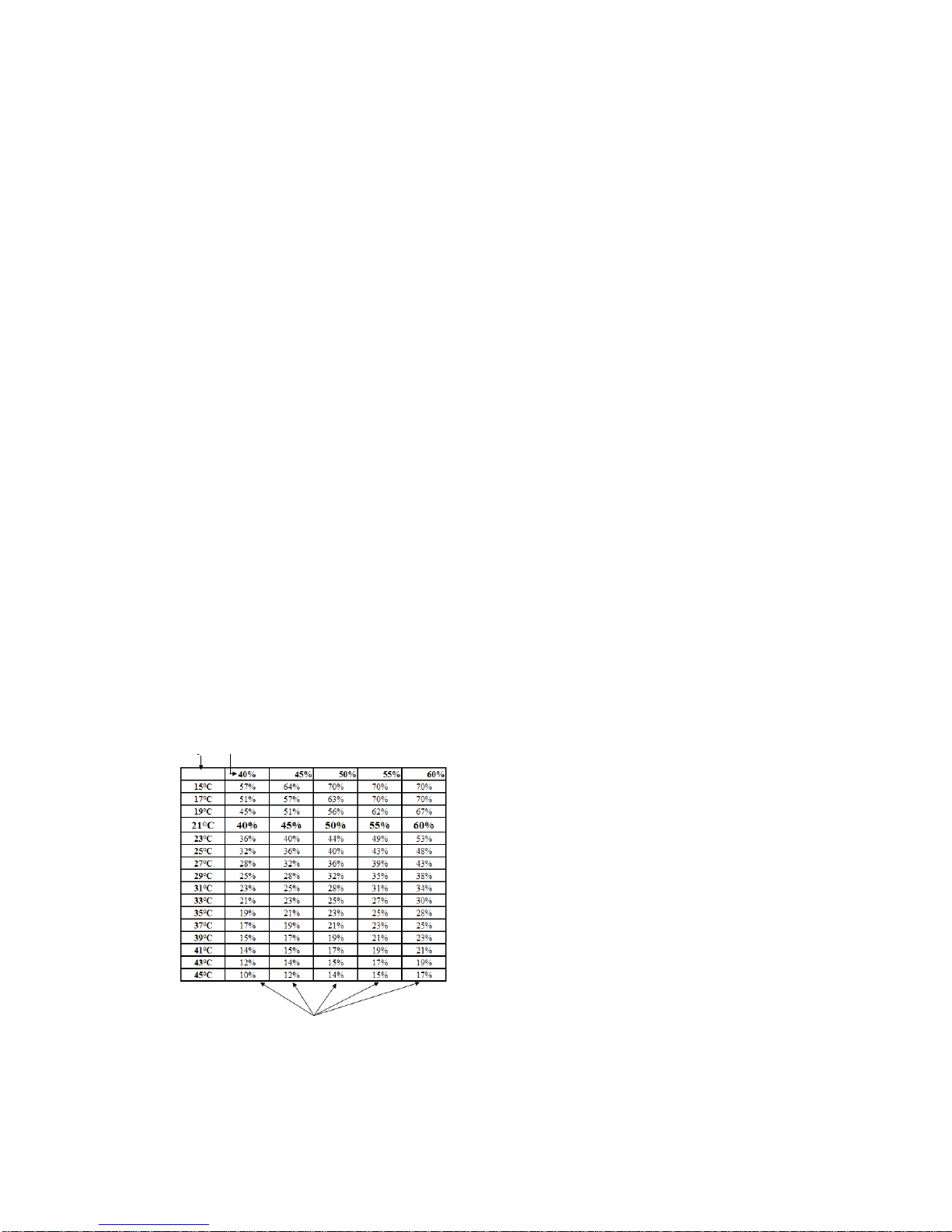
8.2 Humidity control
The air humidity is controlled using the water moistened surface of the bladed rotor and the water level in
the tank. As the water level rises, the rotor blades are submerged more deeply into the water, increasing
the surface area of the blades that becomes wet. The passing air flow absorbs moisture from the wet
blades, in accordance with a specific reference value that is set as a constant. However, as a rule the set
relative humidity is converted to the relevant absolute humidity at 21 °C (factory setting) and then
controlled.
Measured
temperature
Set
humidity
Controlled humidity

8.3 Temperature control
The air outlet temperature of the humidification unit is controlled either by the sensor built into the device
or by an external sensor, where one has been attached. In case of a connected external sensor, the
control system automatically switches to external temperature control. In the display, the letter "E"
appears after the temperature. TemperatureE 21°C<
Function view:
9. Control system
The device is provided in a preprogrammed manner and can be commissioned immediately after all
connections (air, water, and electrical) have been established.
9.1 Operation/keypad/display
The first two lines on the display show the operational menu, the third line shows the operational status.
The display illumination is switched off 10
minutes after the entry of the last command and can be
reactivated by turning the scroll wheel (energy-saving mode).
<Scroll Wheel>: Select or set the position by turning, confirm or save by pressing. The less-than
character on the right edge of the display labels the respectively selected value.
<On/Off>: Activation and deactivation of the device
<Back>: Go back a step in the selection

9.2 Customer menu
(The frame text represents the display view)
9.3 Settings
Temperature 21°C<
With the Temperature parameter, the air temperature at the outlet of the air humidification unit is
set between 15°C and 25°C in one degree intervals. A value of 21°C is preset at the factory.
With the TemperatureE parameter (E = external temperature sensor), the desired air
temperature at the external sensor is set between 15°C and 25°C in one degree intervals.
Humidity 50%<
• With the Humidity parameter, the desired outlet humidity is set between 40% and 60 %
relative humidity at five percent intervals. A value of 50 % relative humidity is preset at the
factory.
Service <
• In the Service menu item, information regarding the operational status is displayed.
Internal Sensor < Temperature 21 °C
Humidity 50 %
Internal Sensor shows the currently measured air temperature and the relative humidity at the
air outlet of the air humidification unit.
External Sensor < Ext. Sensor 21°C
External Sensor indicates the currently measured air temperature at the external temperature
sensor. If a sensor is not connected, the
Ext. Sensor display is not connected!
Info <
Software version
V 1.0 01.09.08
The installed software version is shown under Info.
Delete
Fault <
Delete Yes<
Fault? No
Error messages, which appear in the Info line of the display, are deleted using the Delete Fault
Yes< function.
Expert <
Code?
--------------
• With Expert, you can access the next lower menu level by entering a code. This parameter can
be opened only by the respective expert.
10. Operational statuses
10.1 Automatic activation/
deactivation Autumn/Spring (Auto STANDBY)
The air humidification unit switches on when the air humidity is too low (Autumn) and off when
the air humidity is too high (Spring). The following appears on the display:
Auto STANDBY
If the evaporative power within 24 hours is less than one litre, the device switches off (Auto
STANDBY).
If the humidity undershoots the set humidity by 7% for a period of 24 hours, the air humidification
unit switches on again.
10.2 Automatic activation/deactivation (Auto STANDBY)
If the On/Off button is pressed, the following appears on the display: Auto STANDBY
The air humidification unit is switched off and set to the Auto STANDBY mode.
If the air humidity falls by 7% under the set value for a period of 24 hours, the air humidification
unit switches on again.
10.3 Manual activation/deactivation (Manu STANDBY)
If the On/Off button on the key pad is pressed for longer than 3 seconds, the following appears
on the display: Manu STANDBY
In this operational status, the air
humidification unit remains switched off. The water is drained
and the UVC pipe and the rotor are switched off with a delay of 20 minutes. The air humidification
unit must be switched on again by hand. To do so, press the On/Off button for 3 seconds.
10.4 Automatic activation/deactivation depending on air current ("Control Off")
The humidification is controlled automatically by the operation of the ventilation device. In the
process, an acoustic signal indicates whether the ventilation and air conditioning system is
running.
Depending on this signal, the air humidification unit switches on and off automatically.
CONTROL ON / CONTROL OFF
If the ventilation and air conditioning system is shut down for longer than 18 hours, the air
humidification unit switches off automatically. Auto STANDBY .
During the operation of the ventilation and air conditioning system, it switches on automatically
again.

10.5 Rinsing
The water inlet pipe and the reverse osmosis membrane are protected against germs by the
rinsing program.
The rinsing program is performed automatically once a day while the air humidification unit is
shut down.
"RINSING" is shown in the display.
The rinsing period amounts to 10 minutes and can be cancelled by pressing the "Back" button
10.6 Control on
This parameter indicates that the humidity and air temperature control are active.
10.7 Fill
This parameter indicates that the tank is being filled with water. Manu STANDBY
10.8 Water replacement
The water in the tank is replaced one to four times a day (LBE 250) or twice a day (LBE 500)
depending on the evaporative power and the degree of hardness of the supply water
(corresponds to 1 to 10 litres of water a day / LBE 250 or 2 to 30 litres a day / LBE 500). The
following appears in the display: WAT.REP.
11. Error messages
In the case of error messages, an alarm sounds which can be deactivated by pressing or turning
the <scroll wheel>. The error messages are shown in the display.
After each error message (with the exception of Service and Filter Change), the water is
drained and the air humidification unit is switched off. The error messages can be deleted by
pressing the "Back" button and keeping it pressed for 3 seconds or in the Service menu under
the Delete Fault Yes< item.
After that, the air humidification unit re-enters the operating mode. The expert/Service
department should be informed in case of error messages, with the exception of the Filter
Change message.
11.1 Filter change! (customer)
• The water filter in the water inlet pipe should be changed (see Section 10).
11.2 UVC pip defective! (expert)
The UVC pipe is monitored continuously. A failure is detected automatically. The UVC pipe
should be changed by the expert/Service department every two years. Only original UVC pipes
should be used. In case replica components are used, the warranty extinguishes and a guarantee
of function cannot be provided.
Remedy of the fault only by the expert: Change the UVC pipe under observance of the safety
measures.
11.3 Descaling! (expert)
During operation the UV radiation decreases continuously. As soon as the radiant power drops
below 20% of the calibrated value, this fault message is output.

• Remedy of the fault only by the expert: Open the device under observance of the safety
measures and remove deposits in the tank, on the rotor, on the UVC pipe etc. using descaling
agent and then rinse them with water.
11.4 Pump, outlet defective! (expert)
If the floating switch actuates during the water replacement, the existing water cannot be drained.
Remedy of the fault only by the expert: Check the pump, outlet, and floating switch.
11.5 Humidity too high! (expert)
If the relative humidity exceeds the reference value by 25% for a period of 25 hours, the water is
drained and the unit switches off.
Remedy of the fault only by the expert: Check the inlet value and integrated humidity sensor.
11.6 Humidity too low! (expert)
• If the relative humidity undershoots the reference value by 20% for a period of 25 hours, the
water is drained and the unit switches off.
• Remedy of the fault only by the expert: Check the inlet valve, motor, integrated humidity sensor,
and reverse osmosis membrane for proper function. (Reverse osmosis membrane blocked.
11.7 Service (expert)
• The service message is set to an interval of 8600 operating hours by default.
• Remedy of the fault only by the expert: The device should be serviced according to Section 18.
12. Maintenance (customer): "Filter Change"
The water filter in the water inlet pipe must be exchanged every six months. The filter change i s
displayed automatically by the air humidification unit by the output of the "Filter Change!" err or
message.
a)
Switch off the air humidification unit.
b) Shut off the water supply upstream of the filter unit.
c) Hold the container under the filter housing. (Water may emerge.)
d) Open the filter housing.
e) Remove the filter and replace it with a new one.
f) Close the housing and turn on the water supply again - do not forget to pay attention to se al
tightness.
g) Keep the "Back" button pressed for three seconds. The error message on the display is deleted.
Figure 1 – Filter housing and filter
Where do I order the filters?
Use only original replacement filters.
J. Pichler Gesellschaft m.b.H.
9021 KLAGENFURT
Karlweg 5, Postfach 32
T
+43 (0)463 32769
filter@pichlerluft.a
Designation Item number
Water filter 40E0003A

13. Commissioning
After all complete connections have been established (ventilation, water, and electrical), the air
humidification unit can be commissioned.
Caution!
The device may be commissioned only by qualified experts. The commissioning program
must be completely completed to start the device.
After the mains plug is plugged in, the following appears on the display:
The supply water should be tested using the test strip included in the delivery (immerse the test
strip in water, shake the strip, and check the colour after one minute). The hardness of water
(°dH) determined in this manner should be entered according to the table.
1 = up to 5°dH
1.5 = 6 – 8°dH
2 = 9 – 11°dH
2.5 = 12 – 14°dH
3 = 15 – 17°dH
3.5 = 18 – 20°dH
4 = 21 – 23°dH
4.5 = 24 – 26°dH
After the hardness of water is set, the following appears:
UV calibration
>On Off
"On" starts the UV calibration (the program runs for about three minutes).
Display:
In the case of the UVC calibration, the light output of the UVC pipe is determined and saved as a
calibrated value (= reference value of the new pipe).
When the program is needed, the following appears in the display for 8 seconds:
Calibration successful!
After that, the air humidification unit automatically switches to operating mode.
If no UVC radiation is determined, the following appears on the display:
UVC pipe or sensor defective!
Trans.lock rem?
Yes < No
Calib. Started
Duration: 3 min
Water RUNNING
Circ. Pump On<
Open Mixer On<
Off
Close Mixer On<
Off
Hardness of water
3.0
Only in case of a device water heater battery
Test strip for determining the hardness of water

Remedy of the fault only by the expert:
Check the UVC pipe, series connection unit (green function LED), and sensor board for function.
After the commissioning of the device, the function and operation should be observed for about 15
minutes.
If leaks are found on the water or air side or if disturbing noises are noticed, shut down the device
immediately.
In this case, have the determined faults remedied immediately under observance of the safety
regulations.
If something is not clear or if you have questions, contact the expert/Service department or
manufacturer immediately.
Caution!
After commissioning, the current supply may not be interrupted for longer than one day so that the
hygienic requirements can be observed.
In case of an interruption in the electrical voltage supply of more than 24 hours, the air humidification unit may
become contaminated with germs. In this case, a general cleaning of all components should be performed before
the unit is commissioned. If necessary, components must be replaced.

14. Expert menu
14.1 Expert menu overview
TempControl
Int.Sensor <
Ext.Sensor

14.2 Settings
This shows whether the air temperature is controlled via the internal or external sensor.
In the case of the Int. Sensor display, the outlet air temperature of the air humidification unit is
constantly regulated to the reference value set in the customer menu.
In the case of the Ext. Sensor display, the outlet air temperature is regulated depending on the
external temperature sensor.
According to the mounting site of the temperature sensor (in the extract air line in case of air
heating or after the second air heater battery in case of low-temperature heating), the device
regulates the temperature to the temperature reference value. The air outlet temperature of the
air humidification unit is limited to a minimum of +16°C and a maximum of +35°C by the software.
Hardness of water < Hardness of water
0,3<
Set the existing hardness of water. (See Section 11 "Installation.")
UV calibration < UV calibration
<On Off
The UV Calibration must always be performed when the UVC pipe is exchanged. (See Section
11 "Installation.")
Control by < Air Curr. Meas
Switch Input.
Using Control by <, the parallel control between the ventilation device and the air humidification
unit can be selected.
In the case of the Switch Input presetting, a control cable must be connected from the
ventilation device to the input of the air humidification unit. This cable makes contact whilst the
ventilation device is running and breaks contact when it is shut down.
In the case of the Air Current Measuremen t selection, the operational status of the ventilation
device is automatically determined using the installed microphone and the air humidification unit
is actuated synchronously (factory setting).
Elect. Heating < Elect. Heating Act<
Deact.
The Elect. Heating parameter shows the operational status for the activated heater battery.
When Elect. Heating Act. < is set, the control system is programmed for the actuation of an
electric heater battery.
When Elect. Heating Deact. < is set, the control system is programmed for the actuation of a
water heater battery.

In the following items, the relay outputs can be activated and deactivated manually.
When Elect.Heating Act. is set, the Open Mixer and Close Mixer items are replaced by
and
With the UVC Check parameter is set, the current light output of the UVC pipe is determined.
At the right bottom, the current value and the
value calibrated underneath that (light output of the
new pipe) is displayed. In comparison with the calibrated value, the light output is shown as a
percentage.
This parameter is used to check the function of the floating switch. When the float is raised, the
">" character changes from Off to On.
The opening time for the water valve is set when the water tank is filled (water level after water
replacement).
Setting range: 20 – 600 seconds / Factory setting: 260 seconds
This parameter is used to set the refill time of the water during humidity control. The air humidity
is determined every minute. When the reference value is undershot, the valve is opened
according to a set value.
Setting range: 1 – 70 seconds / Factory setting: 30 seconds
With this parameter, the runtime of the mixer can be set.
Setting range: 2 – 30 seconds / Factory setting: 6 seconds
With the Time Interval Mixer parameter, the interval time according to which the control system
readjusts the mixer can be set.
Setting range: 1 – 120 minutes / Factory setting: 5 minutes
Motor
Motor On<
Off
Valve
Valve On<
Off
Circulation pump <
Cir. Pump On<
Off
Wat.Soft.Pump <
Wat.Soft.Pump On<
Off
Discharge pump <
Disch.Pump On <
Off
Elect.Heating1 <
Elect.Heating1 On<
Off
Open Mixer <
Open Mixer On<
Off
UVC Lamp
UVC Lamp On<
Off
Close Mixer <
Close Mixer On<
Off
Fan <
Fan On<
Off
Horn <
Horn On<
Off
Elect.Heating 2 <
Elect.Heating 3
UVC Check <
UVC check 3.65
80 % Cal. 4.56
Floating switch
Floating switch
<On Off
Time Valve
Wat. Repl <
Time Valve
Wat. Repl <
Time Valve Ctrl.
Time Valve Ctrl.
030s
Runtime Mixer
Runtime Mixer
006s
Time Int. Mixer
Time Int. Mixer
005min

Defines the runtime of the rinsing program.
Setting range: 1 – 20 minutes /
Factory setting: 10 minutes
Indicates the operating hours of the UVC pipe.
Deletes the operating hours meter of the UVC pipe. Can be performed after every UVC pipe
change.
Occurring error messages are logged automatically and can be polled under this menu item.
If Factory Setting is selected in the program, all saved settings are deleted. The control system
must be recommissioned and reset. In addition, a test menu for testing the individual components
appears.
This test program must be performed. Test program sequence:
Test
Successful?
>Yes No
On/Off button
Back button
Horn On<
Off
Floating Switch
>On
Off
Temperature 21°C
Humidity 50%
Time Rinsing
Time Rinsing
010min
UVC Operation <
UVC Operation
00001 h
Reset UVC <
Reset UVC
Yes No<
Error Messages <
01: No Fault
Rec.
Fact. Setting <
Fact.Setting Yes<
Load? No
Motor On<
Off
Valve On<
Off
Elect. Heating Act.<
Deact.
UV Lamp
On< Off
UVC check 3.65
80 % Ca. 4,56
Hi:680 Lo:260
Dta:060 F1 + -3v
Elect.Heating1 On<
Off
Elect.Heating2 On<
Off
Elect.Heating3 On<
Off
Disch.pump On<
Off

• The Elect. Heating parameter is used to set whether the device is equipped with an electric
heater battery (Elect. Heating Act.) or a water heater battery (Elect. Heating Deact.). When the
test program is ended, the mains plug should be pulled for 10 seconds. The test program must
be concluded before you can access the next menu item. After that, proceed with the
commissioning program (see Section 11)
With this parameter, the function of the installed microphone is checked and the sensitivity is set.
The "Hi" (high) and "Lo" (low) values indicate the level for the volume of the air noise generated
by the ventilation device. The greater the difference between the "Hi" and "Lo" values, the greater
the volume.
By reducing the "Dta" value, the sensitivity can be increased.
"F1" visualises whether the humidity control is switched on or, in the case of "F0", switched off.
In case of an air volume flow under 100 m³/h, the noise development of the ventilation device
may be too low for you to detect the operation of the ventilation device. In this case, the device
does not switch on and humidification does not take place.
If the noise development is too low, caused by air volume flows that are too low, a control cable
must be installed and connected between the ventilation device and the switch input of the air
humidification unit (see Section 17).
"Descaling On" starts an automatic descaling program that runs for about 120 minutes.
Program sequence:
1. Draining of the water
2. 5 minute wait while descaling agent is being filled
3. 40 minutes of descaling while the rotor is turning
4. After that, rinse four times
5. At the end of the program, the system automatically switches to the previous operational status.
The descaling program may only be executed by the expert. While the descaling program is
running, the ventilation device must be shut off (odour nuisance).
In the case of Air Heating On, the Time
Interval Mixer parameters and the hysteresis
of the
extract air sensor of the extract air control are adapted.
Status memory
In the menu Status memory the last 9 actions of the control unit can be retrieved with the time stored.
1 CHANGE WATER
2 DESCALE
3 FLUSH
4 UV_CHECK
5 STANDBY
6 CALIBRATE UV
7 CALIBRATE AIR
8 START
9 START USER
0 STANDARD
Air Heating<
Air Curr. Setup
Hi:680 Lo:260
Dta:060< F1 +-3
Descaling
Descaling On
Off
Air Heating On<
Off

Automatic switching-off of the humidifieris deactivated by AutoStby active 'Off'. Additionally, a
number is now shown in the expert menu under AutoStby aktiv ‘off’ at the bottom on the left,
which shows the reason for the AutoStby operation.
1 - No ventilation for 18 hours
2 - EEPROM
3 - Valve openings
4 - Switch
5 - Rinsing
The external temperature sensor can be calibrated here.
The menu guidance can be switched over from German to English or to French and vice versa in
the menu option Language.
If the parameter “Max. air humidity” is set to “On”, the air humidity setting in the customer´s menu
is expanded by the values 70 % an d 80 %.
This parameter must not be activated in an air piping system, if it is integrated into the humidifier
(condensation water
may form in the piping system!)
In the menu “Relative air humidity” the humidity control is switched from the absolute air
humidity vontrol at 21 °C to relative air humidity control.
This parameter must not be activated in an air piping system, if it is integrated into the humidifier
(condensation water may form in the piping system!)
Here the temperature is set, to which the absolute humidity control is related. The value can be set
between 20°C and 24°C in 1-degree increments. This enables the adjustment of the humidity control to
the room temperature.
When the parameter “external Off” is activated to “On” and if the contact is open at the external
switching input, the device is switched to the operating status “Control Off”(For m ore details, see
Section 8.4). Air flow monitoring via the integrated microphone will still remain active.
Displays the parameterized device type. This setting can only be adjusted in the factory defaults menu
item.
Ext. Temp. Offset
Ext. Temp. Offset
+0.0
Ext. Off On
Ext. Off
AutoStby active On
4 Off<
Temp.abs.humid.
Temp.abs.humid.
21°C<
Language
English
German
Max. air humidity
80 %
Max. air humidity
On/Off
Rel. Air humidity
Rel. Air humidity
On/Off
250 <
500
Softwaretyp
AutoStby active

15. Technical data
LBE
250
LBE
500
Air volume flow
m³/h
max. 250 max. 500
Air humidity, adjustable
%
40 - 60
Supply air temperature, adjustable
° C
15 - 25
Evaporative power
l/h
ma x. 2 ma x. 4
Water replacement
l/day
1 -10
2 - 30
Pressure loss
Pa
max. 80
max. 30
Connected load, max.
W
100
Average (in the case of the version with the water heater battery)
W
23
Connected load, max. (in the case of the version with the electric
heater battery)
W
1400 -
Mains connection
V/Hz
230/50
Connection to air supply
mm
ø 160
ø 250
Connection to water supply
inch
ø ¾
Water inlet pressure, min/max
MPa
0,35 - 0,7
Water temperature, min/max
° C
8 – 30
Weight (without/with water)
kg
25/28
46/61
Type of protection for wall mounting
IP
20
Water heater battery
Air volume flow, max.
m³/h
250 500
Medium
water
Temperature of supply line/ return line
° C
55/45
Output
W
2000
4200
Air inlet
° C
15
Air outlet
° C
40
Water volume
l/s
0,05 0,13
Connection ø (copper pipe)
mm
10 22
Water pressure, max.
MPa
1
Water temperature, max.
° C
95
PTC electric heater battery
(only LBE 250!) Heating output of PTC battery
W
1300 -
Three heating sections that can be actuated by the control system depending on the power requirement have
been integrated into the PTC battery. Depending on the air temperature, the heating output of the PTC battery is
adapted automatically. In this way, an economic output control is guaranteed.
Reverse osmosis unit
The water is treated using the reverse osmosis unit.
Any deposits on the bladed rotor, the water tank,
and the UVC pipe are thus reduced to a minimum.
Subject to technical changes.
VENTECH Fertigungs-GmbH is constantly performing technical improvements and optimizations on your products
and reserve the right to modify the devices or technical data without prior notice.
1 LBE 250 with Water heater battery
2 LBE 250 with PTC electric heater battery
3 LBE 250 with water heater battery and low
temperature auxiliary heating unit with integrated
water batter
4 LBE 500 with water heater battery
Hygiene – Type Examination
(Hygiene-Institut des Ruhrgebiets)

16. Dimensions/design variants
16.1 LBE 250
The LBE 250 air humidification unit is available in four designs:
1.
With water heater battery, air inlet on the right side,
designation "LBE250 RW"
2.
With water heater battery, air inlet on the left side,
designation "LBE250 LW"
3.
With electric heater battery, air inlet on the right side,
designation "LBE250 RE".
4.
With electric heater battery, air inlet on the left side,
designation "LBE250 LE"
LBE 250 RW with warm water heater battery
Dimensions L x D x H = 550 x 360 x 385 mm
For connection on the right A= 175 mm / C = 145 mm
1
Inlet
Supply air from ventilation device
ø 160 mm
2
Outlet
Supply air into living areas
ø 160 mm
3
Water outlet
Water outlet
ø 40/50 mm
4
Water supply
Mains water connection
¾ inch
5
UV pipe
Cover for UVC pipe
6
Mains cable
Mains connection 230V/50Hz
7
Supply line
Supply line of heater battery
ø 10 mm
8
Return line
Return line of heater battery
ø 10 mm
LBE 250 RE with PTC electric heater battery Dimensions L x D x H = 515 x 360 x 385 mm For connection on
the right A= 175 mm / C = 145 mm
LBE 250 LW (for connection on the left) LBE 250 LE (for connection on the left)

16.2 LBE 500
The LBE 500 air humidification unit is available in the following design options:
1.
With water heater battery, air inlet on the right side,
designation "LBE500 RW"
2.
With water heater battery, air inlet on the left side,
designation "LBE500 LW"
LBE 500 RW with warm water heater battery
Dimensions L x D x H = 610 x 510 x 560 mm
For connection on the right A = 250 mm/C = 225 mm
1
Inlet
Supply air from ventilation device
ø 250 mm
2
Outlet
Supply air into living areas
ø 250 mm
3
Water outlet
Water outlet
ø 40/50 mm
4
Water supply
Mains water connection
¾ inch
5
UV pipe
Cover for UVC pipe
6
Mains cable
Mains connection 230V/50Hz
7
Supply line
Supply line of heater battery
ø 22 mm
8
Return line
Return line of heater battery
ø 22 mm
LBE 500 LW (for connection on the left)

17. Mounting
For mounting and setup, the national and local regulations must be observed. The device may be installed
only in compliance with the national installation regulations.
The device may be installed only in frost-free, dry rooms. The room temperature must lie between
+5°C and a maximum of +40°C. The device is intended for horizontal mounting. It may deviate a maximum
of +/-1° from the horizontal position and must be mounted to a massive wall that can bear the load. The
intrinsic operating weight of the air humidification unit must be taken into consideration for the suspension.
No shocks or jolts may affect the device.
The installation of the air humidification unit may take place only in rooms that have an existing water
outlet. In addition, safety measures that automatically close the water supply to the air humidification unit
in case of leakage (e.g. safety valve/water connection set) must be taken within the room. Ventilation and
air conditioning system air lines that are not installed in heated areas must be designed with suitable heat
insulation (danger when the dew point temperature is undershot) to prevent the formation of condensation.
The setup site for the air humidification unit must be easily accessible for maintenance and servicing work.
Minimum distance for
installation of the closed unit
25 cm distance LBE 500
20 cm distance LBE 250
Minimum distance for
installation of the closed unit
25 cm distance LBE 500
25 cm distance LBE 250
Remove the transport securing
straps!
Caution!
A minimum spacing of 20 cm (LBE 250) / 25 cm (LB E 500) must be maintained above the air
humidifier. A minimum spacing of 25 cm (LBE 250 / LBE 500) must be maintained below the air
humidifier.
During the installation of t
he ventilation lines, make sure that no metal chips get into the pipework (metal
chips cause corrosion points in the water tank). After the air lines have been cut to size and mounting is
completed, the air lines should be thoroughly cleaned. For any damage due to non-observance of this
information, the warranty extinguishes.
Attach the wall mounting bracket horizontally (max. deviation +/-1°) using fastening screws and dowels
with at least ø 6 mm to a massive wall that can bear the load.
Hang the air humidification unit into the wall mounting bracket and secure it to the device with both lateral
screws.

18. Connections/installation
18.1 Routing of air lines
Caution: The sound absorber must be installed downstream of the air humidification unit, so that the
built-in microphone detects the sound of the ventilation unit, herby the correct operation of the
humidification unit can be ensured.
18.2 Waste water connection
Waste water connection (included in the scope of delivery)
Both waste water connections must be connected loosely in a waste water pipe (HT pipe DN 40 mm or
50 mm), countersunk by about 3 cm. An odour guard (siphon) must be created on site using four
90° pipe bends.
Caution: Do not connect hoses directly to the outlets. The maximum water volume of 2.5 litres is drained
in about eight seconds.

18.3 Mains water connection
Only mains water that corresponds with the local mains water ordinance may be used for the
water supply. For the connection to the water supply, only the original connecting hoses provided
in delivery may be used.
The operating pressure of a minimum of 0.35 MPa and a maximum of 0.7 MPa and a water temperature of
a minimum of 8°C and a maximum of 30°C may not be undershot or exceeded, respectively.
In case of a chlorine content over 0.1 mg/l, the standard water filter (5 μm) must be replaced by a dual
filter (5 μm/carbon) (optionally available as an accessory).
If the iron content of the mains water exceeds a value of 0.1 mg/l, an iron filter should also be built into
the water inlet pipe upstream of the fine filter. The device can be used for a maximum hardness of
water of 26°dH.
When this value is exceeded, the service life of the reverse osmosis membrane is considerably
reduced.
Water connection set (accessory), consisting of:
2 connecting hoses, 1.5 m each 1 safety valve
2 plastic screw connections 1 filter housing
1 wall mounting bracket 1 water filter
Mounting diagram:
Water connection
In case of a defect (leakage), the safety valve closes and the uncontrolled discharge of water is prevented.
To re- establish proper function: close the water valve, remove the hose, unscrew the safety valve, and
press the red button on the output side of the valve.
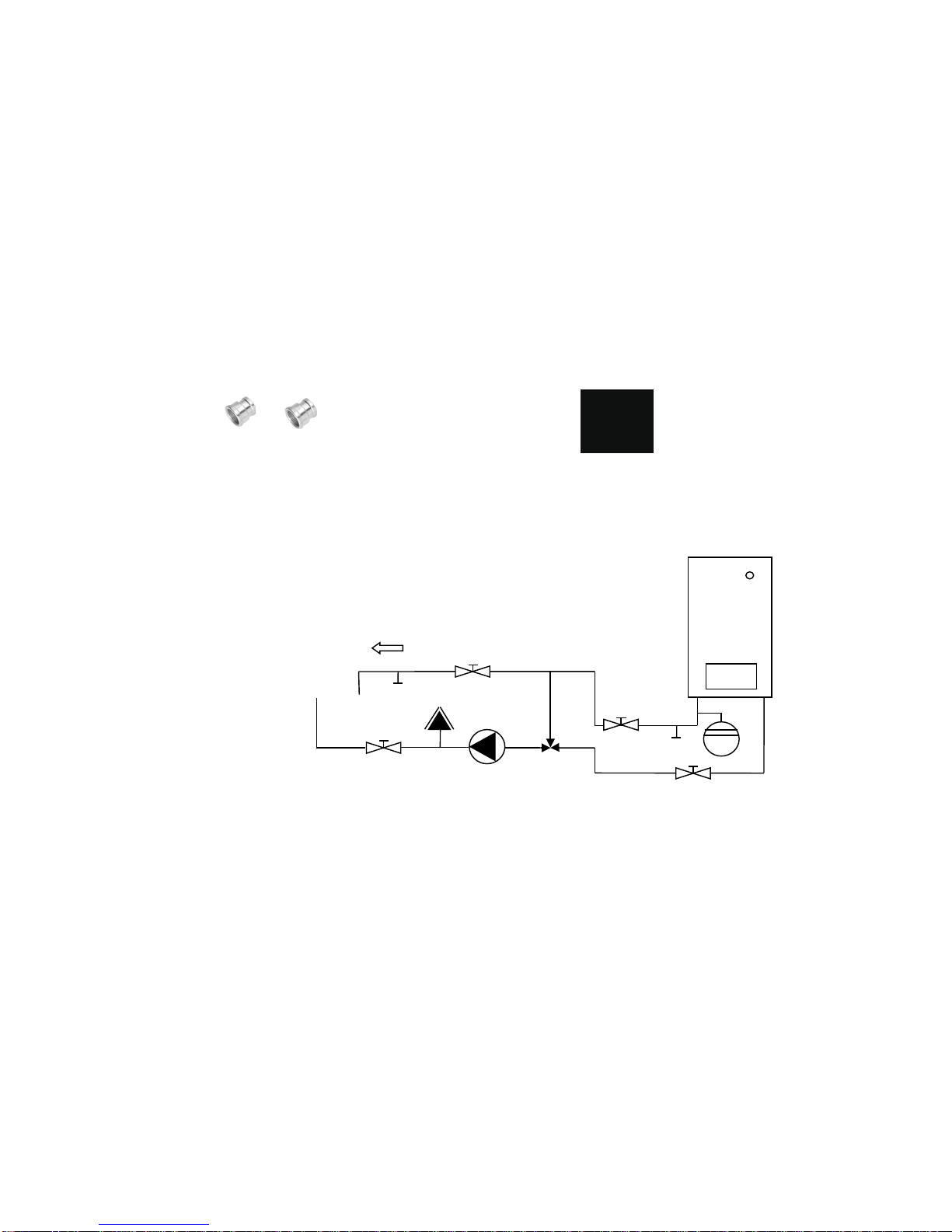
18.4 Water heater battery connection
The heater battery (supply line and return line) is to be connected to the heating system via a circulation
pump and a three-way motor mixer valve. The supply line temperature should amount to at
least 50°C and must be available constantly during the heating period.
Pump/mixer connection set (optional accessory), consisting of:
1 circulation pump 230 V
2 screw connections, R 1/2a / 15 mm MS (brass)
1 three-way mixer valve with actuator 230 V, Rp1/2", DN 15, runtime 120 seconds
Figure 2 – Circulation pump with screw connections Figure 3 – Three-way mixer valve with actuator
18.5 Hydraulic connection diagram (for version with warm water heater
battery): Supply line/return line 55/45°C
Supply line
Heating
system
Air
inlet
Return line

Thermostat-valve body
Straightway, DN 15, (R1/2")
Thermostatic head K withliquidfilled sensor (157 mm total
length, 11mm diameter), and 2 m
capillary tube. Adjustment range
10°C to 40°C.
Fastening socket for
sensor
18.6 Low temperature heating (only LBE 250!):
Supply line temperature of at least +30°C!
In case of low temperature heating, and additional auxiliary heater battery must be installed at the air
outlet downstream of the air humidification unit (see figure), or an outlet temperature below 19 °C at the
internal sensor decreases the humidification, as too little evaporation energy is available.
Water auxiliary heater battery
Caution: The auxiliary heater battery may be mounted only in this position, thus guaranteeing simple
accessibility for a possible UVC pipe exchange.
Connection diagram parallel circuit with thermostatic valve: With this connection variant the system
can be best coordinated and regulated. The heat output of the reheating coil is automatically adjusted by
the thermostat valve* to the integrated heater, with that the highest possible evaporation line is obtained in
connection with the available flow temperature.
The "thermostat sensor*" (Item No.6412-Heimeier 09,500) must be installed in the supply line approx.
50 cm next to the reheating coil.
Connection diagram serial connection (with bypass):
This connection method has the disadvantage that the heat output of the heater cannot be controlled
separately. Should the heat output of the reheating coil be too high, the mixer is added and reduces the
heat output of the integrated heating coil and the humidification.
Feed line
Return line
Air inlet
Heating
system
*

By installing a bypass line with a control valve*, the heat output can be adjusted to both heating coils.
An "external temperature sensor" should be installed into the supply air line, about 50 cm after the
auxiliary heater battery. In low temperature heating systems, the air humidifier LBE-250 can also be
integrated directly (without mixer and external sensors) into the heating system. The supply air
temperature is then not regulated actively.
shut-off valve expansion tank Mixer drain valve automatic vent valve Pump
Feed line
*
Return line
Air inlet
Heating
system
External temperature sensor
19. Wiring diagram

Connecting terminals 1 through 24 are labelled on the motherboard and designed as relay outputs with
230 V (see figure).
In the case of the device design with the water heater battery, the three-way motor mixer valve and the
circulation pump are connected to the following relay outputs:
Three-way motor mixer valve (Terminals 15 through 18): Terminal 15 - Close Mixer phase
Terminal 16 - Open Mixer phase
Terminal 17 - Zero conductor
Terminal 18 - Neutral conductor (earthing)
Circulation pump (Terminals 19 through 21): Terminal 19 - Phase
Terminal 20 - Zero conductor
Terminal 21 - Neutral conductor (earthing)
With Ventilation Device Switch Input, the air humidification unit can be switched on (break contact) and
off (make contact) in parallel with the ventilation device. The switch input must be activated in the Expert
menu if automatic synchronous operation cannot be guaranteed because the sound level is too low.
In the case of External Temperature Sensor, a PT1000 sensor, on the basis of which the air outlet
temperature is controlled automatically, can be connected optionally. This is required only in connection
with a second heater battery (low-temperature heating/air heating).
The floating output can be used for a possible visualisation of faults. For a function check with an
external open-loop and closed-loop control unit.
E-heating 1, E-heating 2 and E-heating 3 and the ventilation device are activ in the case of a device
design with electric heater battery only.
20. Maintenance (expert)
Maintenance may be performed only by expert personnel. After the Service display message appears, the
following tasks should be performed:
1. Before opening the device, pull the mains plug and
secure
against reactivation.
Never look directly into the lit UVC
light source without eye
protection.
Mains
plug
2. Remove the cover for the UVC pipe together with oth
screws.
Sharp edges of plate (danger of injury).
Screws/cover

3. Pull out the UVC pipe by 5 cm, remove the
connecting plug and dispose of the UVC pipe in an
environmentally sound manner.
Sharp edges of plate (danger of injury).
Connecting plug/UVC pipe
Screws/cover
4. Remove both screws on the device cover and lift the
cover.
5. Fold down the front panel of the housing and lift the inner
cover.
Grab the rotor only when wearing gloves since the blades have
sharp edges (danger of injury).
6. Lift out the rotor. (If the motor coupling jams, carefully turn the
rotor into the right position by hand.)
7. Clean the water tank and UVC pipe. In case of scale
deposits, clean with descaling agent and then rinse thoroughly
with water. In the Expert menu, rinsing water can be filled using
"Valve On" and drained again using "Discharge Pump On."
8. During this work step, pay attention to leaking water!
Loosen the hose clamp, pull out the reverse osmosis
housing, and unscrew the cover. Remove the membrane from
the housing and replace it.
9. Install a new UVC pipe of the brand Philips Type TUV 16W
4P-SE. Only original spare parts may be installed. (Caution! Do
not touch the pipe on the glass part!) Press the rubber seal
firmly into the immersion pipe and close it off with the cover.
10. Reassemble the device.
11. Plug in the mains cable.
12. In case of scale deposits in the device and on the rotor, the hardness of water must be set 1 to 2 levels higher
in the Expert menu.
13. Reset the operating hours meter with Reset UVC in the Expert menu.
14. Perform the UVC Calibration in the Expert menu. (See Section 11 "Commissioning.")
15. The maintenance is completed.
22. Subject to change without notice
We are constantly performing technical improvements and optimisations on your products and reserves
the right to modify the devices or technical data without prior notice.
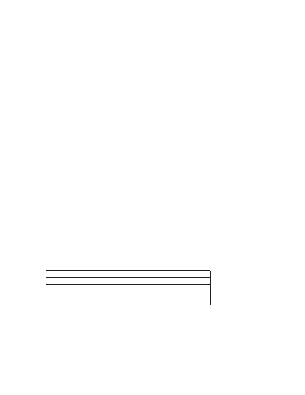
21. Spare parts and accessories
Only genuine spare parts may be installed and used for replacement work and repairs. Dependable operation is ensured
only if genuine spare parts are used!
Designation
Item number
Water filter
UVC pipe
Osmosis membrane (LBE 250)
Osmosis membrane (LBE 500) 2 pcs required
40E0003A
40l0023A
40C0029A
40C0029A

23. EC Declaration of Conformity
Hersteller / Manufacturer: VENTECH Fertigungs - GMBH
Anschrift / Address: Ebentalerstraße 130
9021 Klagenfurt am Wörthersee
Bezeichnung / Product description: LBE 250 / LBE 500
Ausführungen / Type: LBE 250 RE / LE / RW / LW LBE 500 RW / LW
Die bezeichneten Produkte stimmen in der von uns in Verkehr gebrachten Ausführung mit den
Vorschriften folgender europäischen Richtlinien überein:
The products described above in the form as delivered are in conformity with the provisions of the following
European Directives:
2014/35/EU Zur Harmonisierung der Rechtsvorschriften der Mitgliedsstaaten über die Bereitstellung
elektrischer Betriebsmittel zur Verwendung innerhalb bestimmter Spannungsgrenzen
auf dem Markt
On the harmonisation of the laws of the Member States relating to the making available on the
market of electrical equipment designed for use within certain voltage limits
2014/30/EG Zur Harmonisierung der Rechtsvorschriften der Mitgliedstaaten über die
elektromagnetische Verträglichkeit
On the harmonisation of the laws of the Member States relating to electromagnetic compatibility
Die Konformität mit den Richtlinien wird nachgewiesen durch die Einhaltung folgender Normen:
Conformity to the Directives is assured through the application of the following standards:
Eine vom Lieferzustand abweichende Veränderung des Gerätes führt zum Verlust der Konformität.
Product modific
ations after delivery may result in a loss of conformity.
Diese Erklärung bescheinigt die Übereinstimmung mit den genannten Richtlinien, ist jedoch keine Zusicherung
von Eigenschaften. Die Sicherheitsinformationen der mitgelieferten Produktdokumentation sind zu beachten.
This declaration certifies the conformity to the specified directives but contains no assurance of properties.
The safety documentation accompanying the product shall be considered in detail.
VENTECH Fertigungs – GMBH Klagenfurt, 01 August 2016
ÖVE / ÖNORM EN 55014-2:2016-02-01
ÖVE / ÖNORM EN 61000-3-2:2015-04-01
ÖVE / ÖNORM EN 61000-3-3:2014-04-01
ÖVE / ÖNORM EN 60335-1:2012-04-01
ÖVE / ÖNORM EN 60335-2-88:2003-11-01
ÖVE / ÖNORM EN 62233:2009-01-01
ÖVE / ÖNORM EN 55014-1:2012-06-01
J. PICHLER
Gesellschaft m.b.H.
oce@pichlerluft.at
www.pichlerluft.at
AUSTRIA
9021 KLAGENFURT
AM WÖRTHERSEE
Karlweg 5
T +43 (0)463 32769
F +43 (0)463 37548
AUSTRIA
1100 WIEN
Doerenkampgasse 5
T +43 (0)1 6880988
F +43 (0)1 6880988-13
Branch oces
in Slovenia and Serbia.
Sales partners in Germany,
Switzerland and Italy.
Author: J. Pichler Gesellschaft m.b.H.
Photos: Ferdinand Neumüller, Archiv J. Pichler Gesellschaft m.b.H. | Text: J. Pichler Gesellschaft m.b.H.
All rights reserved | All images are for reference only| Subject to amendment | Version: 09/2017 db/kp
Systematic ventilation.
 Loading...