

Montageanleitung
Instruction Manual
# C5103
Technische Daten
Spannweite:
Länge:
Gewicht:
R/C Funktionen:
Servos (empfohlen):
Antrieb „Standard“ (empf.):
+Akku:
+Luftschraube:
Antrieb „Tuning“ (empf.):
+Akku:
+Luftschraube:
1520mm
1080mm
ab 1450g (flugfertig)
Seiten-, Höhen-, Querruder, Gas
4 x Servo DS 3012 [# C4995]
Brushless Combo Set BOOST 25 [#C4390]
LiPo Akku RED POWER 2200 [#C2158]
11*7 [#C2840]
oder:
Brushless Combo Set BOOST 40 [#C2983]
LiPo Akku RED POWER 3200 [#C3164]
12*8 [#C2843]
Specifications
Wingspan:
Length:
Weight:
R/C Functions:
Servos (recommended):
„Standard“ Power (rec.):
+Battery:
+Propeller:
„Tuning“ Power (rec.):
+Battery:
+Propeller:
1520mm
1080mm
from 1450g (flight-ready)
Rudder, Elevator, Aileron, Speed Control
4 x Servo DS 3012 [# C4995]
Brushless Combo Set BOOST 25 [#C4390]
LiPo Battery RED POWER 2200 [#C2158]
11*7 [C2840]
or:
Brushless Combo Set BOOST 40 [#C2983]
LiPo Battery RED POWER 3200 [#C3164]
12*8 [#C2843]
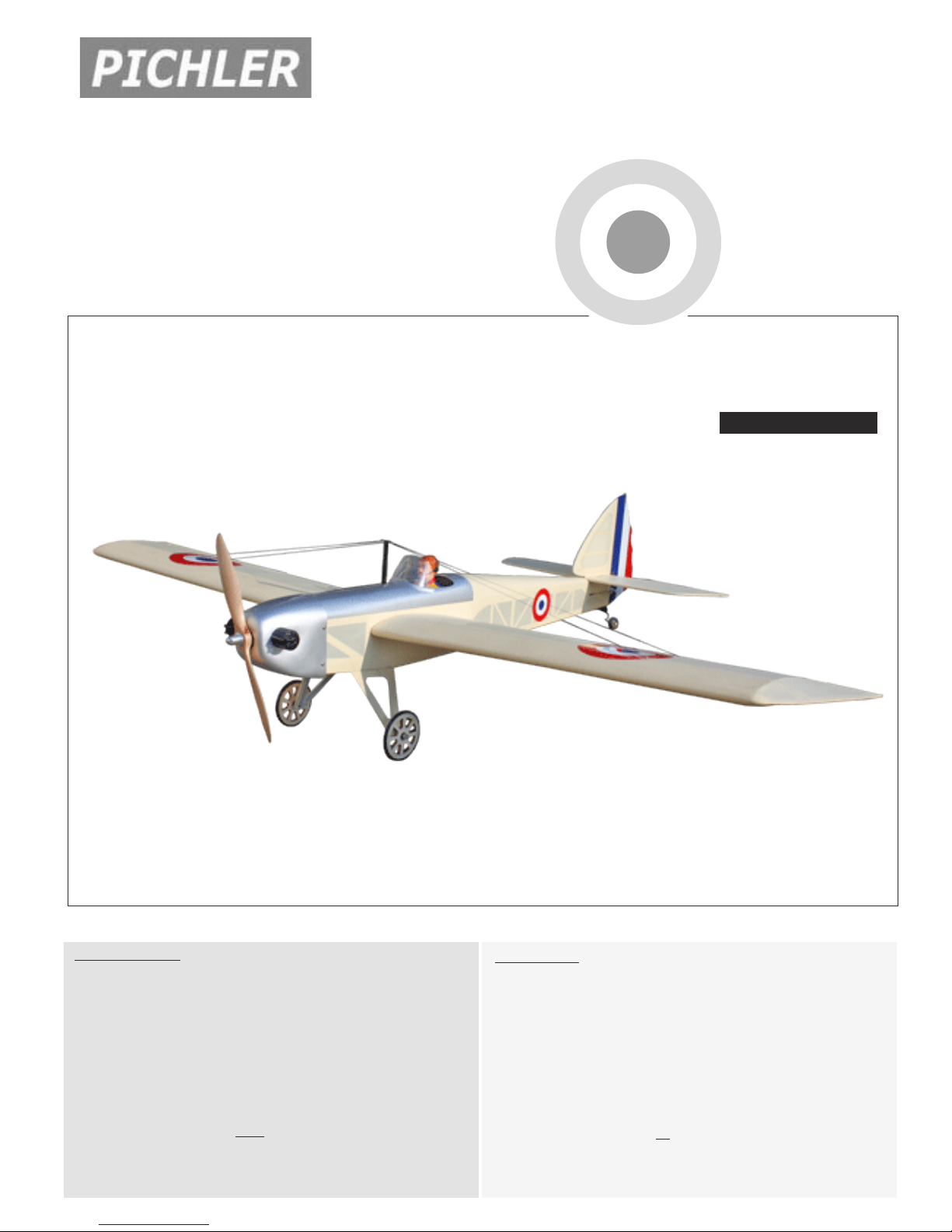
AmeliaAmelia
ARF
ARF
ALMOST READY TO FLY
95% PRE BUILT
R/C Modellflugzeug in Holz-Fertigbauweise
Ergänzungen zu dieser Anleitung und neueste Infos unter:
www.pichler-modellbau.de/downloads
Latest Infos at: www.pichler-modellbau.de/downloads

AMELIA Instruction Manual
This instruction manual is designed to help you build a great flying aeroplane. Please read this
manual thoroughly before starting assembly of your AMELIA. Use the parts listing below to identify
all parts.
WARNING.
Please be aware that this aeroplane is not a toy and if assembled or used incorrectly it is
capable of causing injury to people or property. WHEN YOU FLY THIS AEROPLANE YOU
ASSUME ALL RISK & RESPONSIBILITY.
If you are inexperienced with basic R/C flight we strongly recommend you contact your R/C supplier
and join your local R/C Model Flying Club. R/C Model Flying Clubs offer a variety of training
procedures designed to help the new pilot on his way to successful R/C flight. They will also be able
to advise on any insurance and safety regulations that may apply.
TOOLS & SUPPLIES NEEDED.
Thick cyanoacrylate glue.
30 minute epoxy.
5 minute epoxy.
Hand or electric drill.
Assorted drill bits.
Modelling knife.
Straight edge ruler.
2mm ball driver.
Phillips head screwdriver.
220 grit sandpaper.
90° square or builder’s triangle.
Wire cutters.
Masking tape & T-pins.
Thread-lock.
Paper towels.
Some more parts.
HARDWARE PACK
COWLING.
Landing gear.....
SUGGESTION.
To avoid scratching your new airplane, do not
unwrap the pieces until they are needed for
assembly. Cover your workbench with an old
towel or brown paper, both to protect the aircraft and to protect the table. Keep a couple of
jars or bowls handy to hold the small parts after you open the bag.
PARTS LISTING.
FUSELAGE ASSEMBLY
(1) Fuselage.
WING ASSEMBLY
(1) Right wing half with pre-installed
aileron.
(1) Left wing half with pre-installed
aileron.
Tail section assembly
(1) Vertical stabilizer with preinstalled rudder.
(1) Horizontal stabilizer with preinstalled elevator halves.
NOTE.
Please trial fit all the parts. Make sure you have
the correct parts and that they fit and are aligned
properly before gluing! This will assure proper
assembly. AMELIA is hand made from
natural materials, every plane is unique and
minor adjustments may have to be made. However, you should find the fit superior and assembly simple.
The painted and plastic parts used in this kit
are fuel proof. However, they are not tolerant
of many harsh chemicals including the following: paint thinner, C/A glue accelerator, C/A glue
debonder and acetone. Do not let these chemicals come in contact with the colors on the
covering and the plastic parts.

AMELIA INSTRUCTION MANUAL
SAFETY PRECAUTION.
This is not a toy
+
+ Be sure that no other flyers are using your
radio frequency
+ Do not smoke near fuel
+ Store fuel in a cool, dry place, away from
children and pets.
+ Wear safety glasses.
+The glow plug clip must be securely attached
to the glow plug.
+ Do not flip the propeller with your fingers.
+ Keep loose clothing and wires away from
the propeller.
MAIN PARTS
.
I. AILERON.
C.
D.
B.
A.
A. Cowling.
B. Wing panel.
C. Fuselage.
D . Horizon stabilizer
E.
Vertical stabilizer.
F. Aluminium wing dihedral brace.
SMALL PARTS
1.
F.
.
E.
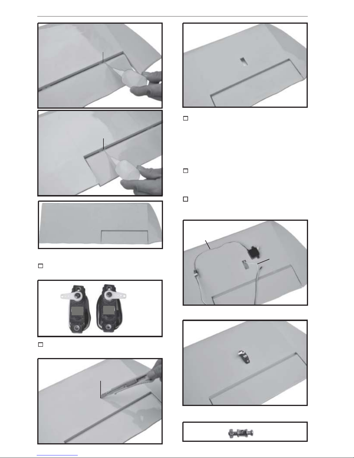
1.INSTALLING THE AILERON SERVOS.
B.
Aileron
Bottom side
C/A glue
1.
2.
3.
5.
1. Wheel
2. Main gear.
3. Gear fairing
4.Tail gear set.
5.Plywood
6. Plastic part gear set.
Motor Mounting Box and Mounting Plate.
5.
4.
Bottom side
C/A glue
6.
AMELIA Instruction Manual
C/A glue
3) Using the thread as a guide and using
masking tape, tape the servo lead to the end
C/A glue
of the thread: carefully pull the thread out.
When you have pulled the servo lead out, remove the masking tape and the servo lead
from the thread.
4) Drill 1,6mm pilot holes through the block
of wood for each of the four mounting screws
provided with the servo.
Aileron
Bottom side
1.INSTALLING THE AILERON SERVOS.
1) Install the rubber grommets and brass
eyelets onto the aileron servos.
2) Using a modeling knife, remove the cov-
ering at possition show below.
5. Instal servo tray with aileron servo into
the wing as same as picture below.
Electric wire
thread
Remove
covering
Bottom of wing.
4

AMELIA INSTRUCTION MANUAL
Mark point
Repeat the procedure for the other wing
half.
INSTALLING THE AILERON
CONTROL HORN.
2mm X 20mm.
1) Using a ruler & pen to draw a straight
line as below picture.
Pen.
Straitgh line.
Secure.
INSTALLING THE AILERON
LINKAGES.
Aileron pushrod.
2) Insert aileron control horn to the aileron.
3) Drill two 2mm holes through the aileron
using the control horn as a guide and screw
the control horn in place.
Aileron pushrod.
5

AMELIA

AMELIA
Balsa
wood
piece
Epoxy glue.
Balsa
wood
piece
INSTRUCTION MANUAL
3. Slide the cowl back over the engine
and secure it in place using four wood screws.
See picture below
4. Install the muffler and muffler extension
onto the engine and make the cutout in the
cowl for muffler clearance. Connect the fuel
and pressure lines to the carburetor, muffler
and fuel filler valve.
Left side
.
3x10mm.
Machine screw.
Front view.
COWLING.
1. Slide the fiberglass cowl over the engine and line up the back edge of the cowl with
the marks you made on the fuselage.
Front view.
2. While keeping the back edge of the
cowl flush with the marks, align the front of
the cowl with the crankshaft of the engine. The
front of the cowl should be positioned so the
crankshaft is in nearly the middle of the cowl
opening. Hold the cowl firmly in place using
pieces of masking tape.
7
VINTAGE.
ELEVATOR INSTALLATION.
SERVO INSTALLATION.
1. Install the rubber grommets and brass
collets into the elevator servo. Test fit the servo
into the servo tray.
2. Mount the servo to the tray using the
mounting screws provided with your radio system.
Instruction Manual
Bottom side
C/A glue
C/A glue
C/A glue
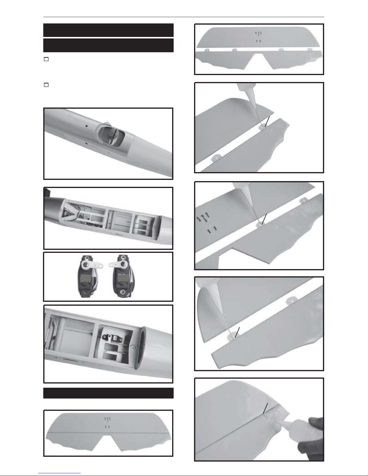
HORIZONTAL STABILIZER.
See pictures below:
Top side
C/A glue
8

AMELIA
INSTRUCTION MANUAL
C/A glue
Remove covering
C/A glue
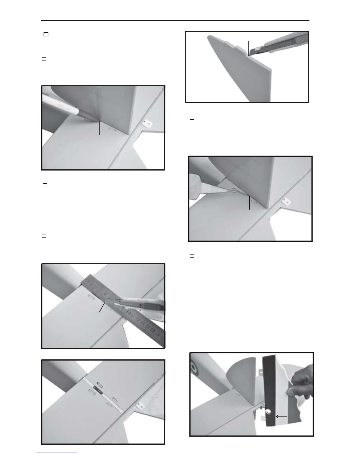
1. Draw a center line onto the horizontal
stabilizer. Then slide the horizontal into the
fuselage.
Center line
2 Using a modeling knife, cut away the
covering from the fuselage for the stabilizer
and remove it.
Remove covering
4. When you are sure that everything is
aligned correctly, mix up a generous amount
of 30 minute epoxy. Apply a thin layer to the
top and bottom of the stabilizer mounting area
and to the stabilizer mounting platform sides
in the fuselage. Slide the stabilizer in place and
re-align. Double check all of your measurements one more time before the epoxy cures.
Remove any excess epoxy using a paper
towel and rubbing alcohol and hold the stabilizer in place with
T-pins or masking tape.
Epoxy glue
3. Remove the stabilizer. Using the lines
you just drew as a guide, carefully remove the
covering from between them using a modeling
knife.
ing to remove it, cut with only enough pressure to only cut through the covering it’s
self. Cutting into the balsa structure may
weaken it. This could lead to possible failure during flight
When cutting through the cover-
5. After the epoxy has fully cured, remove
the masking tape or T-pins used to hold the
stabilizer in place and carefully inspect the
glue joints. Use more epoxy to fill in any
gaps that were not filled previously and
clean up the excess using a paper towel and
rubbing alcohol.
9
AMELIA
Instruction Manual
C/A glue.
Drill a hole 2mm
diameter.
C/A glue.
C/A glue.
ELEVAT
OR CONTROL HORN INSTALLA-
TION.
Elevator control horn install as same as the
way of aileron control horn. Please see pictures below
.
Secure
ELEVATOR PUSHROD INSTALLATION.
Elevator and rudder pushrod install as same
as the way of aileron pushrod
M2
.
M2 lock nut.
2*12mm.
10

AMELIA
INSTRUCTION MANUAL
C/A glue
Elevator
pushrod.
Elevator
vo.
ser
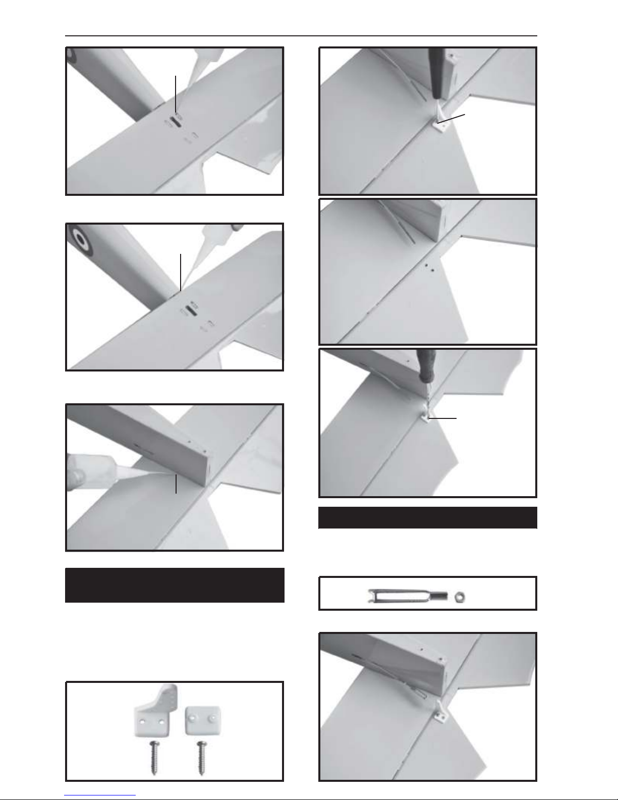
VERTICAL INSTALLATION.
C/A glue
Rudder servo install as same as method of
elevator servo. See picture below:
Elevator
Rudder
servo.
ser
vo.
C/A glue
11
AMELIA
Instruction Manual
2. Put the rudder into the fuselage as
same as picture below.
3. Mark the shape of the vertical on the
left and right side of the rudder on to the horizontal stabilizer using a felt-tip pen.
Mark line
Bottom side
4. Now, remove the rudder and using a
modeling knife, carefully cut just inside the
marked lines and remove the film of the rudder. Just as you did with the horizontal stabilizer, make sure you only press hard enough
to cut the film, not the balsa rudder.
Remove covering
5. Put the vertical stabilizer back i n
place. Using
that the vertical stabilizer is aligned 90 degree to the horizontal stabilizer
a triangle, check to ensure
.
C/A glue
Also carefully remove the covering from
the horizontal fin as below the lines which
you drew as same picture below
Remove covering
.
6) When you are sure that everything is a
aligned correctly, mix up a generous amount
of 30 minute epoxy. Apply a thin layer to the
slot in the mounting platform and to the vertical stabilizer mounting area. Apply epoxy to
the lower rudder hinge. Set the stabilizer in
place and re-align. Double check all of your
measurements once more before the epoxy
cures. Remove any excess epoxy using a
paper towel and rubbing alcohol and hold the
stabilizer in place with T-pins or masking tape.
Allow the epoxy to fully cure before proceeding.
12
AMELIA
INSTRUCTION MANUAL
C/A glue
Secure
C/A glue
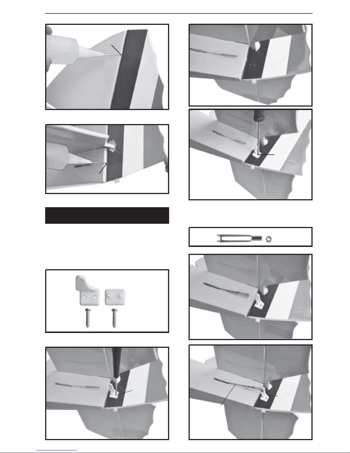
RUDDER CONTROL HORN INSTALLA-
TION.
Rudder control horn install as same as the
way of aileron control horn. Please see pictures below
.
2 x 12mm
M2
RUDDER PUSHROD INSTALLATION.
Rudder pushrod install as same as the way
of aileron pushrod.
M2 lock nut.
Drill a hole
2mm diameter
Rudder
control horn
Rudder
pushrod.
13

AMELIA
Elevator
pushrod.
Rudder
pushrod.
servo.
Rudder
INSTALLING THE MAIN LANDING GEAR.
PARTS
REQUIRED
Instruction Manual
Secure
Drill a hole
2mm diametter
3 x 12mm
Mark point
Secure

AMELIA
Cut
INSTRUCTION MANUAL
C/A glue
15

AMELIA
Instruction Manual
2. Using a pen, mark the locations of the
two mounting screws. Remove the tail wheel
bracket and drill 1mm pilot holes at the locations marked.
Secure
Mark point
MOUNTING THE TAIL WHEEL
BRACKET.
1. Set the tail wheel assembly in place
on the plywood plate. The pivot point of the
tail wheel wire should be even with the rudder hinge line and the tail wheel bracket should
be centered on the plywood plate.
3. Secure the tail wheel bracket in place
using three 3mm x 15mm wood screws. Be
careful not to overtighten the screws.
Secure
3mm x 12mm
16

AMELIA
INSTALLING THE RECEIVER AND BATTERY.
1. Plug the servo leads and the switch
lead into the receiver. You may want to plug
an aileron extension into the receiver to make
plugging in the aileron servo lead easier
when you are installing the wing . Plug the
battery pack lead into the switch.
INSTRUCTION MANUAL
Battery
2. Wrap the receiver and battery pack in
the protective foam to protect them from vibration. Use a rubber band or masking tape to
hold the foam in place.
3. Position the battery pack and receiver
behind the fuel tank. Use two tie wraps t o
hold the battery and receiver securely in place.
As pictures below.
Do not permanently secure the receiver
and battery until after balancing the model.
4. Using a 2mm drill bit, drill a hole through
the side of the fuselage, near the receiver ,
for the antenna to exit.
Tie wrap.
WING ATTACHMENT
Locate the aluminium wing dihedral
brace.
*** Test fit the aluminium tube dihedral brace
into each wing haft. The brace should slide in
easily. If not, use 220 grit sand around the
edges and ends of the brace until it fits prop-
.
erly
.
Tie wrap.
17

AMELIA
WING AT TACHMENT.
See picture wing attach to fuselage.
Wing bolt.
Installing the fuselage hatch as same as picture below
.
Wing bolt.
Instruction Manual
C/A glue
3 x 15mm
e
ecur
S
Secure

VINTAGE. INSTRUCTION MANUAL
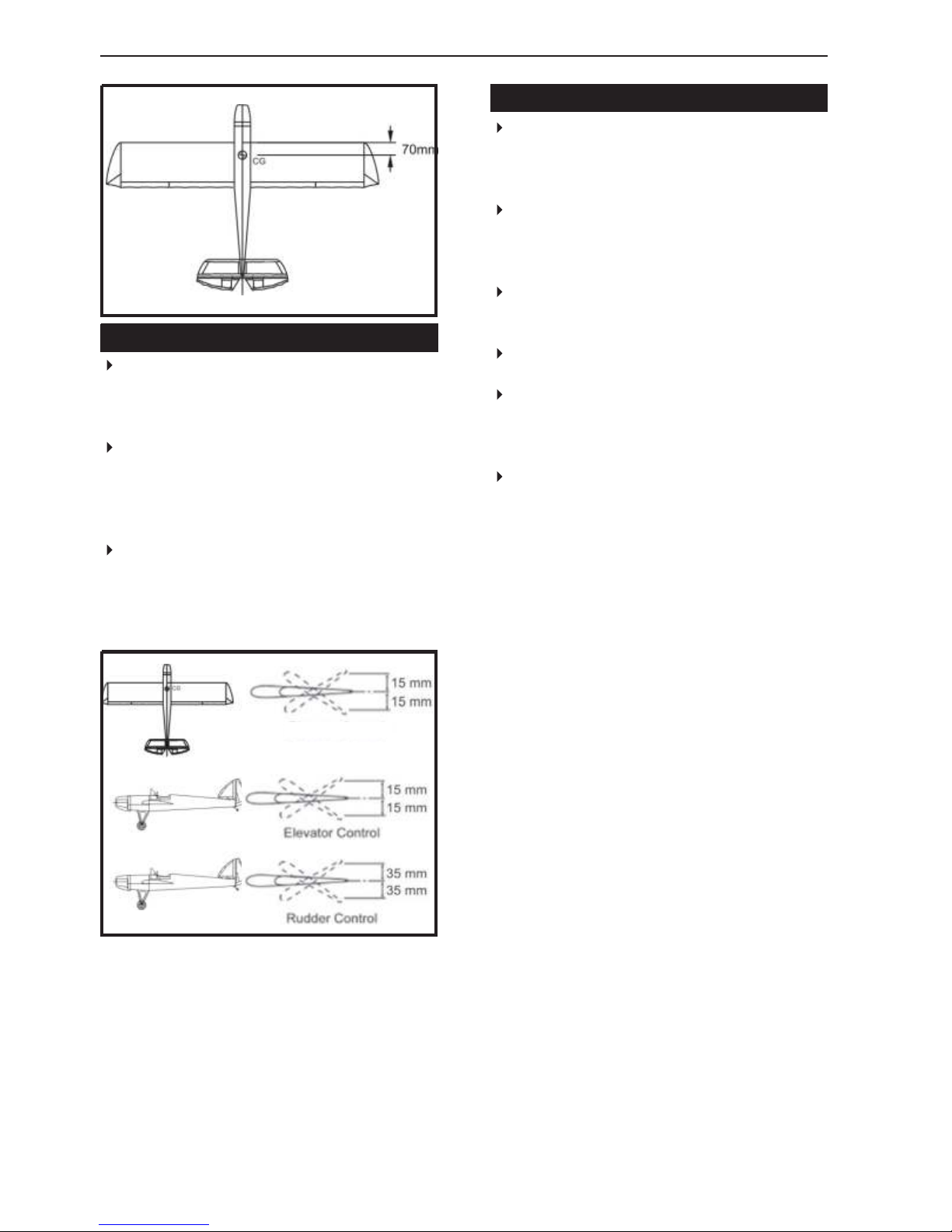
BALANCING.
1) It is critical that your airplane be bal-
3 x 15mm
Secure
anced correctly. Improper balance will cause
your plane to lose control and crash.
THE CENTER OF GRAVITY IS LOCATED
70MM BACK FROM THE LEADING EDGE
OF THE WING.
2) Mount the wing to the fuselage. Using
couple of pieces of masking tape, place them
on the top side of the wing 70mm back from
the leading edge, at the fuselage sides.
3. Turn the airplane upside down. Place
your fingers on the masking tape and carefully lift the plane
Accurately mark the balance point on the top
of the wing on both sides of the fuselage. The
balance point is located 70mm back from the
leading edge. This is the balance point at
which your model should balance for your first
flights. Later, you may wish to experiment by
shifting the balance up to 10mm forward or
back to change the flying characteristics.
Moving the balance forward may improve the
smoothness and arrow- like tracking, but it
may then require more speed for take off
and make it more difficult to slow down for
landing. Moving the balance aft makes the
model more agile with a lighter and snappier
”feel”. In any case, please start at the location we recommend .
Lift the model. If the tail drops when you
lift, the model is “tail heavy” and you must
add weigh* to the nose. If the nose drops, it
is “nose heavy” and you must add weight* to
the tail to balance.
.
a
With the wing attached to the fuselage, all
parts of the model installed ( ready to fly), and
empty fuel tanks, hold the model at the
marked balance point with the stabilizer level.
*If possible, first attempt to balance the model
by changing the position of the receiver battery and receiver. If you are unable to obtain
good balance by doing so, then it will be necessary to add weight to the nose or tail to
achieve the proper balance point.
19
AMELIA
CONTROL THROWS.
1) We highly recommend setting up a
plane using the control throws listed.
2) The control throws should be measured at the widest point of each control surface.
3) Check to be sure the control surfaces
move in the correct directions.
Ailerons : 15mm up 15mm down
Elevator : 15mm up 15mm down
Rudder : 20mm right 20mm left
Instruction Manual
PRE-FLIGHT CHECK.
1) Completely charge your transmitter and
receiver batteries before your first day of flying.
2) Check every bolt and every glue joint in
your plane to ensure that everything is tight
and well bonded.
3) Double check the balance of the
airplane.
4) Check the control surface.
5) Check the receiver antenna . It should
be fully extended and not coiled up inside the
fuselage.
6) Properly balance the propeller.
We wish you many safe and enjoy-
able flights with your
AMELIA
Aileron control
15
15
15
15
20
20
20
 Loading...