

Pichler 08LG250A-R, 08LG250A-L-V, 08LG250A-R-V, 08LG250A-L, 08LG250A Operating And Installation Instructions
...
Systematic ventilation.
optional
COMFORT
VENTILATION
The specified energy eciency
is applicable when controlled to
local requirements and is valid
up to the specified maximum air
flow volume.
EU-Regulation
1253/2014
2016
1254/2014
ENERGIA · ʫʻʫˀʧʰ˔ · ȵɁȵɆȳȵȻȰ · ENERGIJA · ENERGY · ENERGIE ͽEZ'/
LG 250
A
43
dB
250 m³/h
+
A+
A
B
C
D
E
F
G
ErP
2018
OPERATING AND
INSTALLATION INSTRUCTIONS
SYSTEM VENTECH LG 250 A

OPERATING AND INSTALLATION INSTRUCTIONS SYSTEM VENTECH LG 250 A PAGE 2
Changes reserved
USER
GENERALSPECIALIST PERSONNEL
GENERAL 3
1. Introduction 3
2. General 3
3. Authorised intended utilisation 4
4. Safety 6
USER 10
5. Customer service 10
6. Ventilation unit assembly guide for users 10
7. Control units for the user 10
8. Fault & notice messages 18
9. Filter maintenance for users 19
QUALIFIED PERSONNEL 22
Assembly /Installation 22
10. Scope of supply, transport, storage and disposal 22
11. Technical data 23
12. Functionality of the ventilation system 29
13. Operating units 34
14. Assembly 37
15. Electrical connection 41
16. Maintenance and cleaning 46
Commissioning - Service 51
17. Troubleshooting 51
18. Installation/Operation of service software
and firmware updates 52
19. Spare parts and accessories 52
20. Subject to change 52
21. Product data sheets 53
22. EG-Konformitätserklärung (EC Declaration of Conformity) 55

OPERATING AND INSTALLATION INSTRUCTIONS SYSTEM VENTECH LG 250 A PAGE 3
USER
GENERALSPECIALIST PERSONNEL
Changes reserved
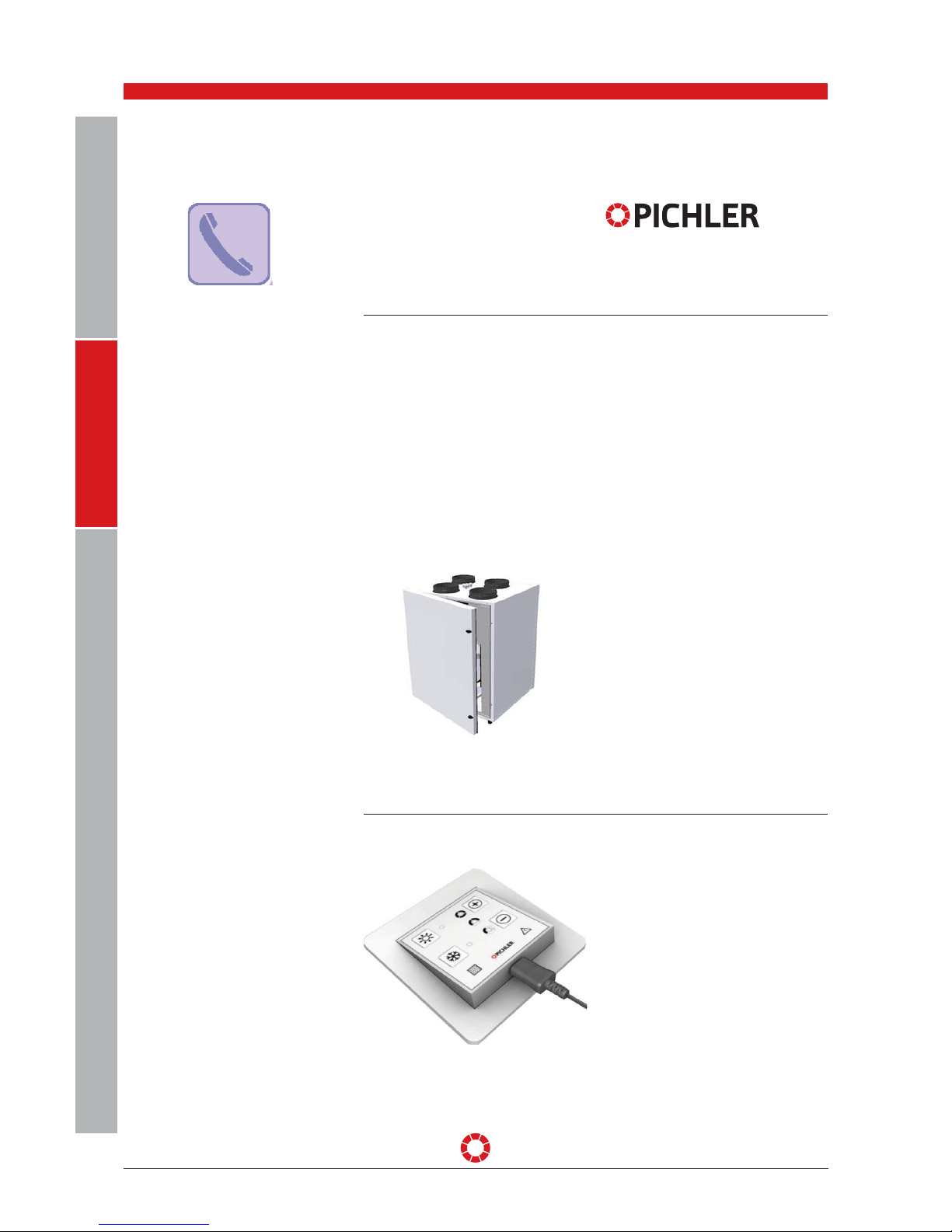
This chapter contains general information
on the LG 250 A System VENTECH compact
ventilation unit with "MINI" or "TOUCH"
control units.
READ THIS MANUAL
CAREFULLY THROUGH
BEFORE
COMMISSIONING!
This Manual contains notes and
information on safe operation and proper
installation of the System VENTECH
LG 250 A compact ventilation unit and
on its use and servicing. Refer to this
Manual during servicing to ensure proper
execution of the tasks. Keep this operating
manual in a safe place and readily
available at all times.
Troubleshooting and tasks on the compact
ventilation unit may only be performed
by an installation company (a specialist
company). These units are subject
to ongoing improvement and further
development. Your unit may therefore
vary slightly from the description in this
manual.
Changes reserved:
This manual has been compiled with
the utmost care. This does not, however,
imply any rights. We constantly strive
to improve and optimise our products
technically and we reserve the right
to modify our apparatus or technical
data fully or in part and without prior
notification.
The latest version of our "General Terms
and Conditions of Trade" is applicable.
1. Introduction
Dear Customer, thank you for purchasing
a LG 250 A System VENTECH compact
ventilation unit.
The LG 250 A System VENTECH
compact ventilation unit employs stateof-the-art technology. It is characterised
by cost eectiveness, ease of use and
reliability.
To operate your compact ventilation unit
safely, properly and economically, please
read this manual carefully and follow the
instructions provided.
Use the ventilation unit only when in
perfect condition and for its designated
use, be aware of safety and any hazards
and cognisant of all the notes and
information contained in this Manual.
Please always keep the model and serial
number (see nameplate on unit) to hand
in case of queries or when ordering spare
parts.
Please contact us if you have any
further questions or if you lose your
documentation.
2. General
J. Pichler Gesellschaft m.b.H.
9021 KLAGENFURT
Karlweg 5, Postfach 32
T +43 (0)463 32769
Gerätetype:
08LG250ALV
Baujahr:
03.2017
Seriennummer:
E170300156
Gewicht:
65 kg
Auftragsnummer:
3700031E
Volumenstrom:
max. 250 m³/h
Abmessung BxHxT:
675x850x595 mm
Spannung/Frequenz:
230V / 50 Hz
Leistungsaufnahme:
max. 1550 W

OPERATING AND INSTALLATION INSTRUCTIONS SYSTEM VENTECH LG 250 A PAGE 4
Changes reserved
USER
GENERALSPECIALIST PERSONNEL
The LG 250 A System VENTECH compact
ventilation unit is suitable for installation
in air-conditioning systems for controlled
mechanical ventilation and deaeration
of spaces and dwellings with purposes
similar, for example, to seminar rooms
and small oces at an adjustable air flow
volume of up to 250 m³/h.
Installation of a mechanical, controlled
domestic ventilation system provides
supply air and exhaust air ventilation for
the entire living area. Controlled air supply
with purified and filtered outdoor air is
provided in supply air areas. Odours and
damp ambient extract air are conducted
away in the extract air area.
The purpose of controlled mechanical
ventilation and deaeration of domestic
areas is to improve air quality, reduce
heating energy demand through use of a
highly ecient heat recovery system, and
to influence indoor air humidity.
The field of application and intended use
of the unit are restricted to use in air
conditioning systems for the extraction
of used air and the supply of fresh,
temperature-controlled outdoor air at
maximum temperatures between
-15°C and +35°C. In addition, the air
supply must be free from aggressive
vapours and substances which are
conducive to wear.
Any other use shall be deemed contrary
to designated use. The manufacturer shall
accept no responsibility for damages
or consequential damages arising from
improper use. Designated use also
includes adherence to our prescribed
operating and installation manual.
This unit is available to the general
public and is intended for installation in
residential or industrial buildings. The
unit is used for mechanical aeration
and ventilation of ambient air and, when
combined with a heater coil, is also used
to reheat air.
This unit is not intended for use by
persons, including children, with limited
physical, sensory or mental capacities
or lacking experience and/or knowledge,
unless under supervision or instruction of
a person responsible for their safety.
The unit is not suitable for outdoor
installation and may be installed in
suitable and temperature-controlled
interior areas only. The ventilation unit is
not suitable for drying new buildings.
The LG 250 A System VENTECH compact
ventilation unit is not a ready-to-use
product. It must not be put into operation
until it has been properly installed and
connected to the ventilation system. Only
qualified and instructed personnel may
work on and with the unit.
Personnel transporting,
installing or working on the unit
must have read and understood
the operating instructions, in particular
Section 4: "Safety". The end user must also
be instructed on potential hazards.
3. Designated use
INTENDED USE

OPERATING AND INSTALLATION INSTRUCTIONS SYSTEM VENTECH LG 250 A PAGE 5
USER
GENERALSPECIALIST PERSONNEL
Changes reserved
Local requirements in terms of standards,
laws and directives, must be taken into
account .
The central air conditioners with heat
recovery should not be installed in
comparably sized rooms, apartments
or facilities with room air dependent
heating apparatus unless:
• safety systems are in place to prevent
simultaneous operation of room air
dependent heating apparatus and units
extracting air, or
• special safety systems will monitor
waste gas extraction of a heating
apparatus dependent on room air.
Heating apparatus running on liquid or
gaseous fuels and drawing in room air,
or air conditioning systems, must switch
o should a safety system trigger. The
air conditioning system must switch o
should the safety system trigger in case
of solid fuel heating apparatus drawing
in room air.
Central air conditioning equipment for
controlled ventilation and extraction of air
in an apartment or similar facility shall
not be installed if the facility has room air
dependent heating apparatus connected
to waste gas units with multiple infeeds.
For normal operation of central air
conditioning systems, it must be possible
to close any ducts for combustion air
or waste gas systems from heating
apparatus dependent on room air. Shuto systems for waste gas from solid
fuel heating apparatus must be manual.
The position of the operating lever must
indicate the status of the shut-o device.
This is deemed complied with if a shut-o
system is used to block soot (soot shuto).
Fire protection requirements
The regional regulatory provisions,
especially the fire protection regulations
for air conditioning of buildings,
as amended, must be taken into
consideration when installing the air
conditioning system in accordance with
the instructions for fire protection.
Due to their heavy burden and irregular
operation, extract air from any kitchen
extractor hoods that may be present
must not be integrated into the dwelling's
air-conditioning system. Extract air from
such extractor hoods must be conducted
separately to the roof by means of an
exhaust air pipe. The supply air must be
provided separately (e.g. by means of
ventilation windows).
Where an extractor hood is operated with
no separate supply of air, the air volumes
in the home will no longer be balanced,
and it will no longer be possible to ensure
the proper function of the home ventilation system (odour extraction, etc.).
Another option is to operate the extractor
hood in recirculation mode.
The LG 250 A System VENTECH compact
ventilation unit has been developed and
manufactured for controlled mechanical
ventilation and deaeration of spaces with
purposes similar, for example, to seminar
rooms and small oces.
Any other use shall be deemed improper
use and may result in personal injury or
damage to the LG 250 A System VENTECH
compact ventilation unit, for which the
manufacturer cannot be held liable.
The manufacturer accepts no responsibility
for any damages due to:
• Non-observance of the Safety,
Operating and Servicing notes in this
Operating and Installation Manual
• Fitting of replacement parts which
were not provided by the manufacturer,
in which case responsibility for the use
of such parts shall lie solely with the
equipment fitter/installer.
• Normal wear and tear
LIABILITY
STIPULATIONS FOR OPERATION WITH
FIREPLACES
STIPULATIONS FOR OPERATION WITH
EXTRACTOR HOODS

OPERATING AND INSTALLATION INSTRUCTIONS SYSTEM VENTECH LG 250 A PAGE 6
Changes reserved
USER
GENERALSPECIALIST PERSONNEL
The warranty period shall commence
after the unit is put into operation, but
no later than one month after delivery.
The warranty shall cover exclusively
the replacement of basic material and
exclude claims based on services.
The warranty shall be subject to proof
of services performed as per our
instructions and executed by a licensed
installer/specialised company.
Warranty claims are valid for a maximum
of 24 months following installation of the
LG 250 A
System VENTECH compact ventilation
unit but are limited to 30 months from the
date of manufacture.
Warranty claims shall be limited to
material and/or constructional defects
occurring during the warranty period.
In the event of a warranty claim, the LG
250 A compact ventilation unit must
not be dismantled without prior written
authorisation from the manufacturer. The
manufacturer's liability shall be limited
to spare parts installed by an installation
company approved by the manufacturer.
The warranty shall automatically lapse at
the end of the warranty period, following
improper operation such as operation
without a filter, if parts other than
original manufacturer-supplied parts are
installed, or if unauthorised changes or
modifications are made to the unit.
The warranty is voided automatically by
failure to comply with the information in
this installation and operating Manual.
WARRANTY
4. Safety
Read this Operating and Installation
Manual carefully and heed the notes on
Safety during installation, commissioning,
general work or maintenance on the
unit. Keep the Operating and Installation
Manual near the unit for its entire service
life.
Always heed the safety regulations,
warnings, instructions and remarks in
this Operating Manual. The specifications
given in this document must not be
altered. Non-observance of these safety
regulations, warnings, instructions and
remarks may lead to physical injury or
damage to the compact ventilation unit.
The conclusion of a service contract is
recommended to ensure that the unit
will be checked at regular intervals. Ask
your supplier about approved specialised
companies/installers in your area.
SYMBOLS USED IN THIS DOCUMENT The following Safety symbols highlight
passages containing warnings in respect
of danger and potential hazards. Please
familiarise yourself with these symbols.
Attention/Note!
Attention! Ignoring this warning
may lead to injury or threat to
life and limb and/or damage to
the unit.
Attention: hazardous electrical
voltage! Ignoring this warning
may result in injury or threat to
life and limb.

OPERATING AND INSTALLATION INSTRUCTIONS SYSTEM VENTECH LG 250 A PAGE 7
USER
GENERALSPECIALIST PERSONNEL
Changes reserved
Installation, initial start-up,
maintenance and repairs must
only be carried out by
an authorised specialist company
(specialised heating company/installer).
Over and above this operating and
installation manual, local and national
regulations and standards shall also
apply to the operation of this unit without
limitation.
Take instruction from your installer on
the unit and on its control unit following
installation. The ventilation unit may only
be used subject to the "Designated use"
section.
All safety and danger notices attached to
the unit must be observed.
In the event of a malfunction, switch o
the unit immediately and secure against
accidental re-activation. Faults must be
remedied immediately.
After repairs and maintenance work,
qualified personnel must verify that the
unit is safe to operate.
Attachment or installation of additional
parts and components is not permitted.
Modifications and alterations to the
LG 250 A System VENTECH compact
ventilation unit are prohibited. Only
original spare parts may be used.
Modifications and alterations to the
ventilation unit are prohibited and absolve
the manufacturer from all warranties and
liability. Ensure that children do not play
with the unit.
SAFETY REGULATIONS
National and local regulations
must be observed during
installation and setup. The unit
may only be installed in compliance with
national installation regulations.
Installation shall be carried out in
accordance with the general local
building, safety and installation
regulations of the relevant community or
the water and electricity department and
other bodies.
The unit may only be installed in frost-free
and dry rooms. The room temperature at
the installation area must consistently
be between a min. of +5°C and a max. of
+40°C.
The unit is designed for upright or wall
installation and may only be set up on
a suitable, load-bearing floor. The unit
must not be exposed to vibration of any
kind. Suitable drainage of condensate
generated when operating the unit will
be required, including eective odour
blocking traps (siphon).
Water, heating and condensate
connections may only be installed by a
specialist. The unit must be installed and
executed appropriately so as to ensure
seal-tightness and eective condensate
drainage in order to exclude the possibility
of building damage. Eective condensate
drainage must be verified on-site prior to
initial start-up and after servicing the unit.
The maximum permissible load must be
observed when transporting the unit.
Components of the ventilation plant,
e.g. air ducts which may need to be
installed in unheated areas, must be
suitably insulated to prevent heat loss or
condensate formation (for temperatures
under dewpoint). Observe all locallyapplicable construction and fire protection
guidelines, regulations and standards. If
necessary, appropriate suitable measures
should be taken when installing the unit
e.g. installation of fire dampers in air
ducts, etc.
UNIT SET-UP

OPERATING AND INSTALLATION INSTRUCTIONS SYSTEM VENTECH LG 250 A PAGE 8
Changes reserved
USER
GENERALSPECIALIST PERSONNEL
The operation of the ventilation
unit is permitted only if all builtin parts provided e.g. silencers
etc., have been properly connected.
The system must be taken
out of operation immediately
in the event of any fault or
damage that may cause harm to persons
or property. Further use must be actively
prevented until the unit is fully repaired!
• Warning: hazardous electrical
voltage!
•
Disregarding the hazard may
result in death, injury or material damage.
•
Before carrying out any work on live
parts, the unit must always be disconnected completely from the power
supply (all poles) and secured against
being switched back on!
The earthed connector-system
to the mains supply enables allpole disconnection of the unit
from the power supply
Electrical connection work as well as
tasks involving electrical plant components may only be performed by authorised electrical engineers in accordance
with national and local regulations.
Before opening the unit and when carrying out work on the unit e.g. maintenance
work and repairs, the unit must be isolated from the mains (all poles disconnected)
and secured against being switched back
on for the duration of the work.
The LG 250 A System VENTECH compact
ventilation unit is designed for a 230 V/50
Hz power supply. The unit is not designed
for connection to a 400 V/50 Hz, threephase supply.
Electrical equipment and the unit's
warning and protective devices must be
inspected regularly to ensure that they
are in perfect working order. In the event
of faults in the electrical power supply
or identification of defects e.g. loose connections or burnt cables, the unit must be
switched o immediately.
Damaged or faulty power supply cables to
the unit must be repaired immediately to
avoid hazards.
The unit may not be operated until safe
operational conditions are restored.
Fault finding and immediate remediation
of electrical defects and malfunctions
shall be carried out by authorised electricians only. All protective measures must
be inspected (e.g. earth resistance etc.)
after completion of electrical work on the
unit.
For details, see Section 15: "Electrical
Connections"
Work practices that could
compromise the unit's
safety are prohibited!
To ensure safe operation, safety devices must not be removed or bypassed.
ELECTRICAL CONNECTION WORK
PLANT OPERATION

OPERATING AND INSTALLATION INSTRUCTIONS SYSTEM VENTECH LG 250 A PAGE 9
USER
GENERALSPECIALIST PERSONNEL
Changes reserved
The ventilation unit must be switched
o and disconnected from the mains
supply immediately in the event of a fault
message or damage. Be aware of your
safety and of hazards when opening the
front covers or removing cover plates.
Work practices that aect the safety of
the unit are prohibited. The unit may only
be operated with connected air ducts and
installed system components such as
acoustic dampeners and with a minimum
duct length of 1000 mm so as to ensure
that fans or electrical components cannot
be touched.
The ventilation unit may be operated
only in accordance with the
project documentation. The project
documentation shall comply with the
Equipment and Product Safety Act and the
pertinent provisions of the EC Directives
and Standards.
Consider environmental impacts and
refrain from installing the ventilation
units in the vicinity of flammable liquids
or gases, in swimming pools or in areas
exposed to chemicals.
Never operate the ventilation unit without
an air filter. Air filters must be checked
regularly for dirt and damage and
cleaned or replaced if necessary. The air
filters must be changed at least every
six months or when the "Change Filter"
message appears on the control unit. Use
original replacement filters only. If the
plant is not used in summer, the air filters
must, for hygienic reasons, be replaced
prior to restarting.
Comply with safety requirements and
standards when operating the ventilation
unit simultaneously with ambient airdependent fireplaces or extractor hoods.
When using fireplaces dependent on
ambient air, a combustion air supply must
be provided separately. See the provisions
on this topic under the section "Provisions
for operation with fireplaces".
Due to their heavy burden and irregular
operation, extractor hoods must under
no circumstances be integrated into
the exhaust or extract air circuits of the
ventilation unit. See the provisions on this
topic under the section "Provisions for
connection with extractor hoods". Exhaust
air extractor hoods must be operated
via separate air pipes with suitable air
replenishment e.g. by means of window
ventilation or in air recirculation mode.
OPERATING AND INSTALLATION INSTRUCTIONS SYSTEM VENTECH LG 250 A PAGE 10
Changes reserved
USER
GENERALSPECIALIST PERSONNEL
The LG 250 A System VENTECH compact
ventilation unit is used for controlled,
mechanical ventilation and deaeration of
homes, large residential units and oces
and for similar purposes.
The scope of application normally extends
to living spaces between 80 m² and
approx. 200 m², with an adjustable air
flow of up to 250 m³/h.
The LG 250 A System VENTECH compact
ventilation unit comprises:
•
A compact, non-heat bridging and
thermally-insulated housing made from
galvanised steel sheeting, externally
powder-coated in RAL 9010
•
A high-eciency heat recovery system
with air/air-counterflow heat exchanger
made from recyclable plastic with an
eciency level of approx. 92 %
•
An automatic 100% bypass with energy-
saving DC radial fans with constant
airflow control,
•
Air filter, quality grade F7 or F9 in supply
air and G4 in extract air
•
Internally wired electronic control
system
•
A "MINI" or "TOUCH" OPERATING UNIT
(optional) , for standing or wall mounting
in spaces free from frost.
5. Customer service
Please contact the installer of your
ventilation and air conditioning system
or contact us directly for any questions
relating to the LG 250 A System VENTECH
compact ventilation unit supplied.
USER GUIDE
J. Pichler Gesellschaft m.b.H.
9021 KLAGENFURT
Karlweg 5, Postfach 32
T +43 (0)463 32769
6. Ventilation unit assembly guide for users
The following compact ventilation unit
functions can be configured with the
"MINI" control unit.
• Ventilation level of the ventilation unit
•
Switching between summer and winter
modes
• Display of filter change messages
•
Display of possible fault
messages with the LEDs provided for
this purpose.
•
Air flow volume for levels I to III can be
adjusted in certain areas using a combination of buttons.
•
In addition, the unit can be switched to
Standby mode or Basic Ventilation mode.
"MINI" CONTROL UNIT
7. Control units for the user

OPERATING AND INSTALLATION INSTRUCTIONS SYSTEM VENTECH LG 250 A PAGE 11
USER
GENERALSPECIALIST PERSONNEL
Changes reserved
4 buttons
The ventilation unit is operated by means
of 4 buttons.
Summer/Winter mode:
The two buttons on the left-hand side
are used to switch between summer and
winter mode.
Summer / bypass modes support cooling
of the living area. The bypass circumvents
the heat exchanger and the cold outdoor
air is blown directly or via a ground collector into the living area.
The outdoor air is always conveyed via the
heat exchanger in winter operation.
Modifying the ventilation levels:
The two buttons on the right-hand side
change the unit’s ventilation level. Pressing the [+] button increases the ventilation
level until level III is reached which corresponds to boost ventilation. After 1 hour
operating time in the highest ventilation
level, normal ventilation mode is automatically reset to Level 2. The boost ventilation may, alternatively, also be stopped
manually after one hour. Pressing the [-]
button reduces the ventilation level.
Basic Ventilation operating mode:
If the ventilation level is less than I, the
unit switches to Standby mode or to Basic
Ventilation operating mode. A minimum
volume flow of 30 m³/h is configured.
7 LEDs:
The ventilation unit's various statuses are
signalled via a total of 7 LEDs. Three LEDs
display the current ventilation level.
If the unit is in
"Basic Ventilation" mode, this can be seen
from the gentling flashing of ventilation
level I.
On the left-hand side, the LEDs for summer and/or winter modes are arranged
beside the corresponding buttons.
Filter change required:
The potential need to change the filter is
signalled by the LED on the bottom left.
For details on filter replacement, see
Section 9
Fault messages
The LED for fault messages can be seen
on the lower right-hand side. Please con-
tact your installer!
For details on fault messages, see
Section 8
BUTTONS AND LEDS
OPERATING AND INSTALLATION INSTRUCTIONS SYSTEM VENTECH LG 250 A PAGE 12
Changes reserved
USER
GENERALSPECIALIST PERSONNEL
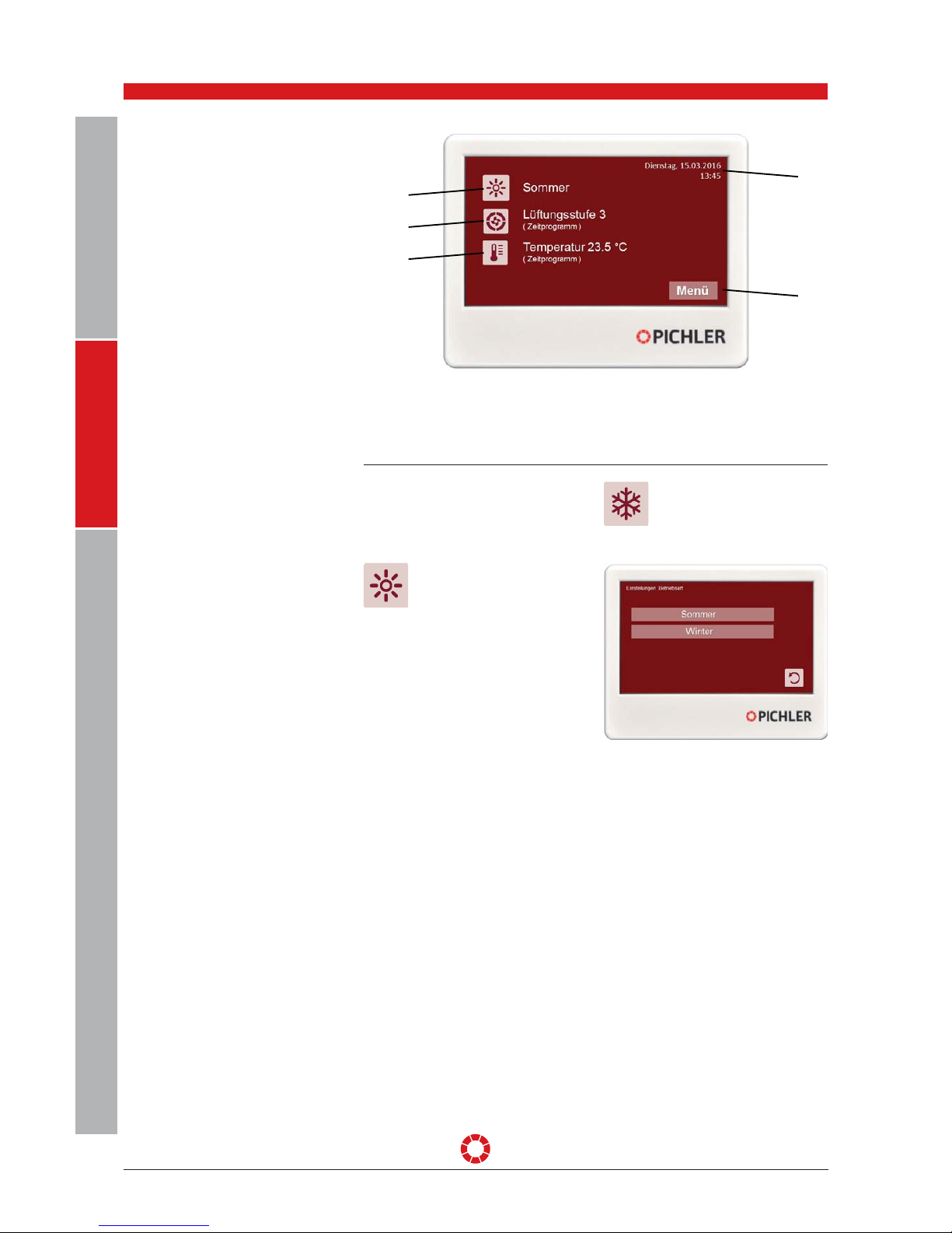
“TOUCH” CONTROL UNIT
1 Current operating mode
2 Ventilation level
3 Temperature (ambient air, supply air, extract air)
4 Menu
5 Date and time
1
2
3
5
4
OPERATING MODE The active operating mode is displayed by
various buttons. The operating mode can
be changed by pressing the buttons. The
following operating modes are available:
Summer:
Summer or bypass mode supports cooling of the living area.
The bypass circumvents the
heat exchanger and the cold outdoor air
is blown directly or via a ground collector
into the living area.
Winter:
The outdoor air is always conveyed via the heat exchanger in
winter operation.

OPERATING AND INSTALLATION INSTRUCTIONS SYSTEM VENTECH LG 250 A PAGE 13
USER
GENERALSPECIALIST PERSONNEL
Changes reserved
VENTILATION LEVEL The active ventilation level is displayed by
various buttons. The ventilation level can
be changed by pressing the buttons. The
following selection options are available:
Time program:
The system runs at the ventilation level
that is currently programmed. The time
program can be programmed in the
"Menu" under "Settings".
O*:
The machine is switched o.
Basic ventilation*:
The unit runs with
basic ventilation
Ventilation level 1:
The unit runs at ventilation
level 1
Ventilation level 2:
The unit runs at ventilation
level 2
Ventilation level 3:
The unit runs at ventilation
level 3
The two buttons on the right-hand side
change the unit’s ventilation level. Pressing the [+] button increases the ventilation
level until level III is reached which corresponds to boost ventilation. After 1 hour
operating time in the highest ventilation
level, normal ventilation mode is automatically reset to Level 2. The boost ventilation may, alternatively, also be stopped
manually after one hour. Pressing the [-]
button reduces the ventilation level.
*Depending on the configuration of the
plant!
Basic ventilation activated: The user cannot switch o the unit.
Basic ventilation deactivated: The user can
switch o the unit.
Basic ventilation can only be activated and
deactivated by service engineers!
In principle: “Ventilate
as much as necessary”
Adjustment of air volume requires
relevant expertise and is performed by a
specialist during initial start-up.
If ventilation is too low, poor ambient air
quality or mould formation may result in
living areas.
If ventilation is too high, ambient air may
become too dry - particularly in the colder
months.
Superior air volume control
There are various configurations and
operating modes that result in the unit
being operated with air volumes other
than those defined.
These include:
• CO
2
concentration-based control
• Humidity concentration-based control

OPERATING AND INSTALLATION INSTRUCTIONS SYSTEM VENTECH LG 250 A PAGE 14
Changes reserved
USER
GENERALSPECIALIST PERSONNEL
TEMPERATURE
The Main menu is opened by pressing
the Menu button. Information on the
ventilation unit is displayed here, and
various settings can be made and actions
performed.
The user is returned to the
Start menu by pressing the
Home button.
•
Set the required temperature in stand-
ard mode
•
Activate/deactivate the time program
•
Ambient air, extract air or supply air is
controlled, depending on the control
setting configured by the specialist
MAIN MENU
Current operating values, operating hours,
messages and firmware versions can be
retrieved under the “Information” menu
item.
Current operating values
Time meter
Fault signal
INFORMATION

OPERATING AND INSTALLATION INSTRUCTIONS SYSTEM VENTECH LG 250 A PAGE 15
USER
GENERALSPECIALIST PERSONNEL
Changes reserved
Current errors and error and filter logs
can be displayed here.
Current error
Error log
Filter log
Firmware
Firmware versions for control and display
are displayed here, as well as ventilation
unit model and ventilator model.
Air volume
Volume flow can be adjusted for each
individual ventilation level here (min. and
max. volume flows are preset).
Three times can be specified for each
day using the time program. These times
determine the time at which a particular
ventilation level is activated.
SETTINGS

OPERATING AND INSTALLATION INSTRUCTIONS SYSTEM VENTECH LG 250 A PAGE 16
Changes reserved
USER
GENERALSPECIALIST PERSONNEL
Temperature
Temperatures for standard mode and
setback mode can be configured here. In
addition, three times can be specified for
room temperature each day. These times
determine the time at which a particular
ventilation level is activated.
Air filter changed
If the air filter has been changed, the filter
service time can be reset here so that a
filter warning no longer appears on the
display.
Date & time

OPERATING AND INSTALLATION INSTRUCTIONS SYSTEM VENTECH LG 250 A PAGE 17
USER
GENERALSPECIALIST PERSONNEL
Changes reserved
Language
The user can switch between Deutsch,
English, Français, Nederlands, Ceský,
Slovenskí and Italiano.
The following errors can be reset under
"Actions":
Standard for LG 250 A - no function:
Reset controlled
GL (Basic Ventilation)/OFF
Reset error Z04/Z05
The + and – options are displayed by
pressing the “No” button. The error is
reset by selecting "Yes" and confirming
with "OK".
Error Z04/Z05
One of the two fans is blocked or has no
power supply, no control voltage signal or
no tachometer feedback. Perform reset
only after remedying the error!
ACTIONS
OPERATING AND INSTALLATION INSTRUCTIONS SYSTEM VENTECH LG 250 A PAGE 18
Changes reserved
USER
GENERALSPECIALIST PERSONNEL
“TOUCH” CONTROL UNIT
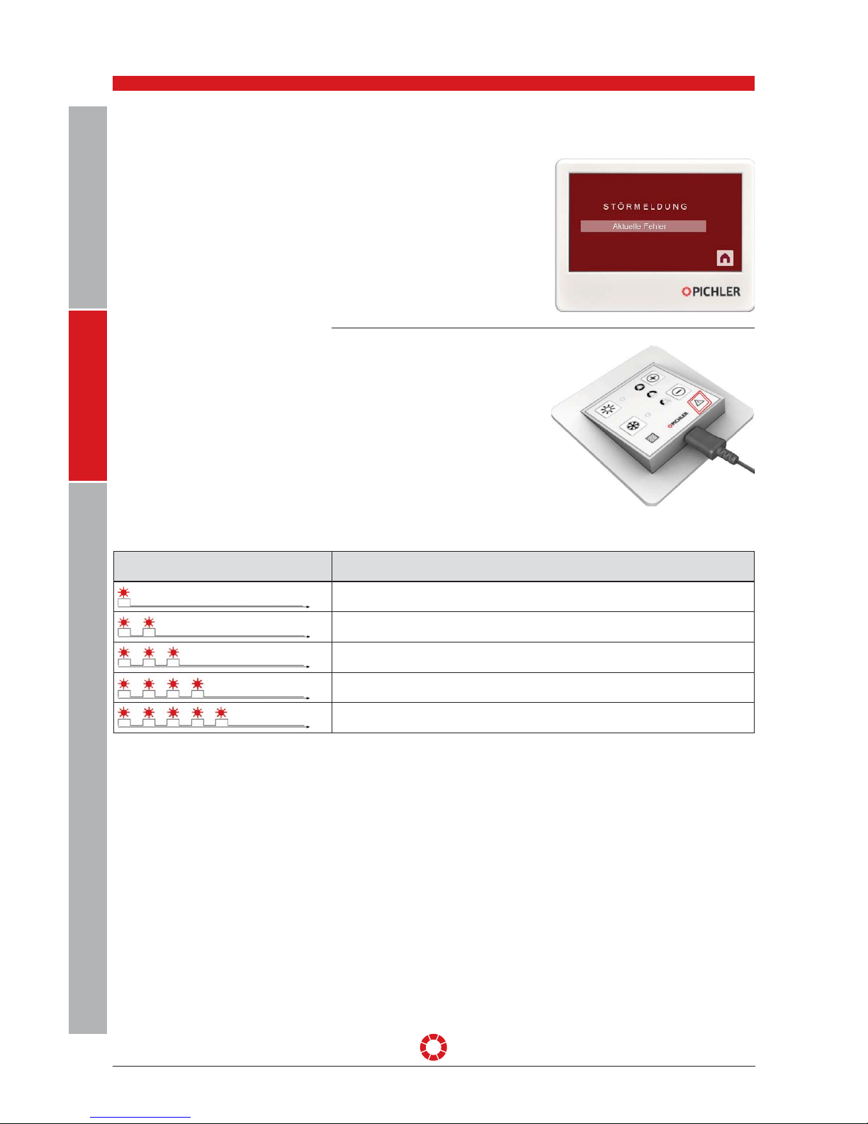
8. Fault & notice messages
Error signal Reason for error
Supply air fan out of service
The error LED flashes once, followed by a long pause
Extract air fan out of service
The error LED flashes briefly twice in succession, followed by a long pause
Temperature sensor error
The error LED flashes briefly three times in succession, followed by a long pause
General fault
The error LED flashes briefly four times in succession, followed by a long pause
Communication between power section and control unit interrupted
The error LED flashes briefly five times in succession, followed by a long pause
The ventilation unit's fault status is indicated on the operating unit by the flashing
pattern of the fault LED.
Please contact your installer.
“MINI” CONTROL UNIT
*See pages 17/18 for detailed descriptions
Please contact your installer.

OPERATING AND INSTALLATION INSTRUCTIONS SYSTEM VENTECH LG 250 A PAGE 19
USER
GENERALSPECIALIST PERSONNEL
Changes reserved
These instructions relate exclusively to regular inspection,
maintenance and replacement
of air filters by the user.
Check the condition of the air
filters regularly
Filter change interval
Filters must be replaced imme-
diately if very dirty. Otherwise,
they should be replaced at least
twice a year, depending on outdoor air
pollution levels.
Only original replacement filters of the
specified quality class may be used.
9. Filter maintenance for the user
1 Exhaust air filter, coarse dust filter class G4
2 supply air filter, fine dust filter class F7,
optionally F9 as a pollen filter
MAINTENANCE INSTRUCTIONS
(AIR FILTER)
1
2
When the filter service time has elapsed
(factory setting: 2,900 hours), the control
unit signals the need for a filter change
through the LED provided for this purpose,
which lights yellow continuously.
FILTER MESSAGE ON THE "MINI” CONTROL UNIT
The control unit reminds the
user of filter maintenance at
regular intervals (filter service
time: 2900 hours)!
FILTER MESSAGE ON THE "TOUCH" CONTROL UNIT
1
2

OPERATING AND INSTALLATION INSTRUCTIONS SYSTEM VENTECH LG 250 A PAGE 20
Changes reserved
USER
GENERALSPECIALIST PERSONNEL
When replacing the air filters,
avoid soiling the unit and its
components. Dirty air filters
must be immediately and suitably disposed of.
It is advisable to package the air filters in
an airtight container immediately after
removal to avoid contamination of the
ventilation system and the unit.
Before carrying out any work
on live parts, the unit must
always be disconnected com-
pletely from the power supply
(all poles) and secured against being
switched back on!
1. Filter message on control unit
2. Undo the wing nuts on the housing
cover.
3. Open the front doors.
4.Before drawing the air filters out from
the unit, release the filter stentering rails.
Only then may the air filters be easily
lifted out and replaced.
5. Extract the filter.
ATTENTION: Never operate the
ventilation unit without using air
filters!
6. Insert the new filter. Please note: Only
original replacement filters of the specified quality class may be used.
Note the installation position
(direction of ventilation) of the
filter!
7. When inserting the new filter, ensure
that it is installed correctly, and close the
filter stentering rails.
8. Close the housing cover and secure it
with the wing nuts. When replacing the
cover, ensure that it is completely closed
and that there is sucient seal-tightness
between the front cover and the unit
housing.
Where can I order filters?
Use only original replacement filters of
the filter quality class specified.
FILTER CHANGING
J. Pichler Gesellschaft m.b.H.
9021 KLAGENFURT
Karlweg 5, Postfach 32
T
+43 (0)463 32769
filter@pichlerluft.at
Designation Item no.:
Supply air filter quality grade F7 standard
40LG050060
Extract air filter quality grade G4 standard
40LG050050
Supply air filter quality grade F9 standard
40LG050070
1 Filter stentering rails
2 Air filter
1
2
2
1

OPERATING AND INSTALLATION INSTRUCTIONS SYSTEM VENTECH LG 250 A PAGE 21
USER
GENERALSPECIALIST PERSONNEL
Changes reserved
Filter change required:
Reset the filter counter after changing the
filter.
Press the [+] button and the [-] button at
the same time for 5 seconds in order to do
this. The filter message disappears after
entering this combination.
Premature filter changing:
If the air filters are replaced prematurely,
the filter counter must be reset without a
pending filter message.
Press the [+] button and the [-] button at
the same time for 5 seconds in order to
do this..
CLEARING FILTER MESSAGES
Reset the filter signal on the control unit
after every filter change! The filtering time
can also be reset later in the settings.
If the air filter has been changed, the filter
service time can be reset here so that a
filter warning no longer appears on the
display.
“TOUCH” control unit
“MINI” control unit

OPERATING AND INSTALLATION INSTRUCTIONS SYSTEM VENTECH LG 250 A PAGE 22
Changes reserved
USER
GENERALSPECIALIST PERSONNEL
10. Scope of supply, transport, storage and disposal
The scope of supply includes:
• The ventilation unit with the "MINI"
control unit, optional: "TOUCH"
• The operating and installation manual
• The wall mounting bracket
On delivery of the unit, check that the
type and serial number on the nameplate
correspond with the information on
the order and delivery documents,
that the equipment (including optional
accessories) is complete, and that all
parts have been delivered in perfect
condition.
Note: Any transport damage
and/or missing parts must be
reported immediately in writing
to the forwarder or supplier.
SCOPE OF SUPPLY
The LG 250 A System VENTECH ventilation
unit range is supplied with transport
packaging. The safety markings on the
packaging must be observed.
The LG 250 A System VENTECH compact
ventilation unit must be handled with care
in order to prevent possible damage due
to forceful impact during transportation.
• Unit dimensions
( W x H x D): 672 x 870 x 610 mm
• Weight: approx. 65 kg with no optional
accessories
Ensure that the unit is not damaged from
being toppled or overturned. Avoid knocks
and blows during transportation.
Applicable safety and accident
regulations must be complied with during
transportation. If transported manually,
ensure that necessary human lifting and
carrying forces are reasonable.
TRANSPORT AND PACKAGING
The unit must be stored in its packaging
in suitable dry, dust-free rooms and
protected from frost. Avoid storing for
more than one year.
STORAGE
Care must be taken to ensure that the
packing material and protective packaging
are disposed of in an environmentally
friendly manner.
The packaging materials must be
disposed of in accordance with local
regulations; wooden pallets or cartons
must be recycled, for instance.
Units that are no longer
in working order must be
dismantled by a specialised
company and properly disposed of via
suitable collection centres in accordance
with the Waste Electrical and Electronic
Equipment Ordinance (WEEE), which
provides for the implementation of
community law, Directive 202/95/EC
(RoHS) and Directive 2002/96/EC (WEEE
Directive).
DISPOSAL
GUIDE FOR SPECIALIST PERSONNEL

OPERATING AND INSTALLATION INSTRUCTIONS SYSTEM VENTECH LG 250 A PAGE 23
USER
GENERALSPECIALIST PERSONNEL
Changes reserved
Ventilation unit
Dimensions:
(W x H x D) 672 x 870 x 610 mm
Thermally-insulated housing in single
formwork design, made from galvanised
steel sheeting, coated in RAL 9010 – white
Air line connector:
4 x ø 160 mm
Condensate connector:
ø 15 mm on underside
Electrical connection:
230 V/50 Hz/16 A
Protection class:
IP 20
Permissible unit ambient temperature:
+5°C to +40°C
Permissible external air temperature:
-15°C to +35°C
Weight with no accessories:
approx. 65 kg
"MINI" and "TOUCH" operating unit
Dimensions "MINI" (W x H x D):
80 x 80 x 19 mm
Dimensions "TOUCH" (W x H x D):
110 x 84 x 25 mm
Connector cable to output component:
Cable J-Y(ST)Y 2 x 2 x 0.8, shielded,
max. length < 100 m
Air filter
External air/supply air filter:
Compact filter quality class F7,
Optional quality class F9
Exhaust air filter:
Compact filter quality class G4
Fans (default setting)
Air flow rate setting range:
80 to 250 m³/h, adjustable in 5 m³/h steps
Power eciency in accordance with PHI:
0.30 W/m³/h
Stand-by mode input:
1.9 W
Heat exchanger
Counterflow heat exchanger made from
plastic
Heat provision level in accordance with
PHI: 88%
Comfort criterion in accordance with PHI:
T
ZUL
= +18.2°C at T
AUL
= -10°C
Housing thickness (in accordance with PHI)
external tightness < 0.6%
within pressure range between 50 Pa and
300 Pa
internal tightness < 1.0%
based on average air volume flow
11. Technical data
UNIT DATA
Ventilation
stages
Stage I Stage II Stage III
Air volume
flow
[m³/h]
80 160 250
Power consumption at
external 50
Pa/100 Pa
[W]
24/33 37/50 70/91

OPERATING AND INSTALLATION INSTRUCTIONS SYSTEM VENTECH LG 250 A PAGE 24
Changes reserved
USER
GENERALSPECIALIST PERSONNEL
The characteristic curves shown are valid
for the unit version with Class F7 supply
air and G4 extract air air filters, as well as
the version with no PTC preheater coil.
The rated overall output comprises the
power consumption of the two supply
and extract air fans as well as the power
consumption of the control system.
CHARACTERISTIC CURVE - EXTERNAL
PRESSURE INCREASE – AIR VOLUME
FLOW RATE
ACOUSTIC DATA Level I = 80 m³/h / Level II = 160 m³/h/
Level III = 250 m³/h at external pressure
increase of 100 Pa
Note: Tolerances ± 2 dB for acoustic data
Measuring
point
Housing
radiation
Outdoor air
connection
Supply air
connection
Exhaust air
connection
Extract air
connection
Level I II III I II III I II III I II III I II III
63 Hz
Lw in dB
55 57 57 64 65 65 79 80 81 76 73 75 66 69 67
125 Hz 50 53 55 55 59 61 67 71 73 69 69 71 52 57 60
250 Hz 41 45 50 51 57 60 63 70 73 62 65 70 49 55 59
500 Hz 35 38 42 39 44 46 55 61 66 55 55 60 34 42 45
1000 Hz 32 36 40 30 33 37 55 62 66 54 56 59 24 31 36
2000 Hz 22 27 34 19 24 29 46 56 61 46 48 53 21 31 36
4000 Hz 15 17 25 12 17 22 39 49 55 39 42 48 17 28 33
8000 Hz 18 18 18 11 12 15 35 46 52 35 37 44 12 17 23
Total
LWA in dB(A)
39 42 46 45 49 52 60 67 70 59 61 65 43 48 51
The LG 250 A System VENTECH compact
ventilation unit is used for controlled,
mechanical ventilation and deaeration of
homes, large residential units and oces
and for similar purposes.
The scope of application normally extends
to living spaces between
80 m² and approx. 200 m², with an
adjustable air flow of up to
250 m³/h.
The LG 250 A System VENTECH compact
ventilation unit, comprising a compact,
non-heat bridging and thermally-insulated
housing made from galvanised steel
sheeting, externally powder-coated in
RAL 9010, a high-eciency heat recovery
system with air/air-counterflow heat
exchanger made from recyclable plastic
with an eciency level of approx. 92%,
automatic 100% bypass, with energysaving DC radial fans with constant
flow regulation, Class F7 in outdoor air
and Class G4 extract air air filters, an
internally wired electronic control system
and a “MINI” control unit (optional).
"TOUCH" for floor or wall mounting in
frost-free spaces.
VENTILATION UNIT

OPERATING AND INSTALLATION INSTRUCTIONS SYSTEM VENTECH LG 250 A PAGE 25
USER
GENERALSPECIALIST PERSONNEL
Changes reserved
• LG 250 A compact ventilation unit with
PHI passive house certification
• Ventilation unit with high-eciency heat
recovery
• Supply air and extract air fan with
energy-saving EC motors
• Electronic volume flow control for
constant air volume flow, adjustable up
to approx. 250 m³/h. The set air volume
flow is maintained even in the event of
a change in system pressure, e.g. in the
event of filter contamination
• With simple "MINI" ventilation unit with
adjustable Basic Ventilation mode.
• Optional comfortable "TOUCH" operating
unit with integrated room temperature
sensor
• Integrated 100% bypass for bypassing
the heat exchanger in Summer mode
• Selectable automatic frost protection
switch for heat exchanger, optionally
available with PTC low-temperature
preheater coil
• Integrated filter monitoring, "Filter
replacement" message on operating unit
once time interval has elapsed
• Filter replacement possible without
tools
• Optional reheating for additional
increase in room temperature
1 "MINI" type operating unit
2 "TOUCH" type operating unit (optional)
3 Output component
4 Connector cable, J-Y(ST)Y2x2x0.8
5 Outdoor air filter, quality class F7
(optional pollen filter, quality class F9)
6 Exhaust air filter, quality class G4 (optional M5)
7 Counterflow heat exchanger
(optional enthalpy heat exchanger)
8 Condensate drain
9 Frost protection heater with PTC low temperature
preheater coil (optional)
10 Bypass flap with electrothermal
servo motor
11 Supply air fan
12 Extract air fan
13 Front cover with handwheel bolt
14 Air line connection
15 Cable inlets, 4x M16 / 1 x M12
ADVANTAGES AND FEATURES
DEVICE CONFIGURATION
3
5
6
7
8
9
10
12
11
13
14
15
1
2
12
5
9
7
8
10
14
15
13
6
3
11

OPERATING AND INSTALLATION INSTRUCTIONS SYSTEM VENTECH LG 250 A PAGE 26
Changes reserved
USER
GENERALSPECIALIST PERSONNEL
1. "MINI" control unit
The “MINI“ control unit, installed in the
living area, is used to easily control the
ventilation unit. Its ease of operation
enables the manual setting of ventilation
levels, switching between summer and
winter modes, the setting of base volume
flows, etc. The mode and current faults
are also displayed.
2. "TOUCH" operating unit (optional)
The “TOUCH“ control unit is easy to use
and provides an overview via a TFT touch
display. It should be installed at a central
location in residential buildings so that
users have access to control and an
overview of messages at all times. The
integrated temperature sensor records
the current ambient temperature and
ensures that supply air is regulated
correctly.
3. Output component
The output component installed in the
ventilation unit is used by the installer or
service technician to set the individual
operating parameters, based on the
respective on-site application. The
settings can be made either using the
operating unit or via a PC interface and
communications software.
4. Connecting cable J-Y(ST)Y2x2x0.8
A screened cable Y(ST) YYx2x0.28 is
required to establish a connection and for
communication between the control unit
and control board. Cable length must not
exceed 100 m.
5. Outdoor air filter, quality class F7
(optional pollen filter, quality class F9)
The outdoor air filter filters dust and dirt
from the outdoor air.
6. Exhaust air filter quality class G4
(optional M5)
Coarse contaminations are filtered out of
the extract air via the extract air filter.
7. Counterflow heat exchanger
The ecient heat exchanger extracts the
energy content from the extract air and
transfers this to supply air.
Optional enthalpy heat exchanger
available.
8. Condensate drain
Condensate generated during the
operation of the heat exchanger is
directed into the condensate tray. The
connected condensate drain, which
passes through an eective odour trap
(siphon), drains the generated condensate.
9. Frost protection heating with PTC low
temperature preheater coil (optional)
Used to prevent the condensate from
freezing in the heat exchanger at very
low exterior temperatures. The optional
electric PTC low temperature preheater
coil preheats the outdoor air based on the
outdoor and exhaust air temperatures.
When an optional water battery
or brine battery is used to
provide frost protection for the
heat exchanger, this must be
provided with appropriate frost protection.

OPERATING AND INSTALLATION INSTRUCTIONS SYSTEM VENTECH LG 250 A PAGE 27
USER
GENERALSPECIALIST PERSONNEL
Changes reserved
The LG 250 A System VENTECH compact
ventilation unit is available in several
dierent versions:
• Right or left, depending on position of
supply air connection.
• Version with or without electrical PTC
preheater coil integrated into the ventilation unit.
10. Bypass flap with electrothermal servo
motor
Used in Summer mode to transfer the
air flow to the heat exchanger when the
outdoor air temperature is lower than the
room temperature.
11. Supply air fan
Ensures the air volume flow for supply
air, directs processed outdoor air into the
living area.
12. Extract air fan
Ensures the air volume flow for extract
air, directs used air from the house into
the open air.
13. Front cover with handwheel bolt
The front cover is easy to open for
maintenance on the unit.
When replacing the cover, ensure that
it is completely closed and that there is
sucient seal-tightness between the front
cover and the unit housing.
14. Air pipe connections
Serve as a connection to the air pipe
system. Correct connection to supply air,
extract air, outdoor air and exhaust air
must be ensured during assembly.
15. Cable guides
The ventilation unit is normally supplied
complete with electrical wiring. The cable
guides are used to create the electrical
connections to connect the operating unit
with optional system accessories such as
temperature sensors, etc.
Version
Left-hand version Right-hand version
Item no. without integrated
preheater coil
08LG250A-L 08LG250A-R
Item no. with integrated
preheater coil
08LG250A-L-V 08LG250A-R-V
With optional enthalpy heat
exchanger for moisture
recovery
08LG250A + 08EWTLG250 08LG250A + 08EWTLG250
For stand or
wall mounting
1
2
3
4
MODEL TYPES
1 Supply air
2 Extract air
3 Outdoor air
4 Exhaust air
3
1
4
2

OPERATING AND INSTALLATION INSTRUCTIONS SYSTEM VENTECH LG 250 A PAGE 28
Changes reserved
USER
GENERALSPECIALIST PERSONNEL
47 282 14
3
1
81
76
1
5484
67
2
1
0
2
1 Supply air ø 160 mm
2 Extract air ø 160 mm
3 Outdoor air ø 160 mm
4 Exhaust air ø 160 mm
5 Counterflow heat exchanger
6 Extract air fan
7 Supply air fan
8 Control system
9 Bypass flap
10 Exhaust air filter G4
11 Outdoor air filter F7
12 Condensate tray
13 Cable inlet 4 x M16 / 1 x M12
14 PTC electric preheater coil (optional)
15 Height-adjustable feet
16 Condensate outlets
Structural diagram (stand or wall mounting, left-hand version)
Structural diagram (stand or wall mounting, right-hand version)
484
544
672
332
92
778
610
633
4
3
1
2
13
215
276 181
13 0
272
19 1
143 282 247
9
10
7
6
8
15
12
5
14
11
16
870

OPERATING AND INSTALLATION INSTRUCTIONS SYSTEM VENTECH LG 250 A PAGE 29
USER
GENERALSPECIALIST PERSONNEL
Changes reserved
To ensure safe operation of the system,
safety devices and covers must not be
rendered inoperative; nor may measures
be taken to bypass or dismantle them.
The system must be taken out of
operation immediately in the event of any
fault or damage to the ventilation unit that
may cause harm to persons or property.
Further use must be actively prevented
until the unit is fully repaired!
The unit may only be restarted by a
specialist installer.
Overheating protection: A
thermo-bimetal switch
is built into the optional,
integrated frost protection heater or the
optional reheater coil to protect against
overheating. If a temperature of +50°C
is reached, power supply to the electric
battery is interrupted and the anti-freeze
heating is switched o.
SAFETY DEVICES
With mechanically-controlled residential
ventilation, used, damp extract air is
conducted away from wet domestic areas,
e.g. bathroom, toilet and kitchen, and
is replaced with fresh, processed and
filtered outdoor air in lounge areas e.g. in
living rooms and bedrooms.
Significant energy savings are achieved
when the system is operated continuously
thanks to highly ecient heat exchangers
for heat recovery from extract air and use
of energy-ecient fans with the latest
DC technology for air flow control. This
technology is particularly eective in
air-tight building shells and with active
thermal insulation. An eciency factor of
up to 92% heat recovery provides highly
ecient energy savings.
It must in particular be ensured that the
heat exchanger is protected against frost
by means of an appropriately adjusted
frost protection strategy, and that eective
condensate drainage is ensured.
12. Functionality of the ventilation system
SYSTEM DESCRIPTION
PTC-Niedertemperaturregister mit
Schutzabdeckung
Thermo-Biemetallschalter
optionales PTC-Niedertemperatuur-
Heizregister-Einheit für Frostschutz
PTC low temperature coil with protective
cover
Thermo-bimetal switch
Optional PTC low temperature
heater coil unit for frost protection

OPERATING AND INSTALLATION INSTRUCTIONS SYSTEM VENTECH LG 250 A PAGE 30
Changes reserved
USER
GENERALSPECIALIST PERSONNEL
The basic design of a domestic ventilation system is
illustrated in the pictorial schematic with optional
additional system enhancements.
1 Unit housing
2 Supply air fan with EC technology
3 Extract air fan with EC technology
4 Outdoor air filter for fine dust F7
(optional quality class F9 pollen filter)
5 Extract air filter G4 for coarse dust
6 Counterflow heat exchanger
7 Bypass flap for Summer mode
8 Frost preheating heat exchanger (optional)
9 Condensate tray with onsite drainage and
eective odour trap (siphon)
10 Pipe connection
11 Silencer (optional)
12 Switching flap (optional)
13 Reheater coil - electrical or
with water (optional)
14 Geothermal exchanger EWT (optional)
15 Suction element with pre-filter G4 for EWT
16 Sole-geothermal exchanger (optional)
Outdoor air
Air supply
Outgoing air
Exhaust air
+/-
Outdoor air
+
+
Bypass
EWT
5
4
8
2
3
1
6
7
9
14
15
12
12
16
13
11
10
15
There is a risk of the heat
exchanger freezing on the
exhaust air side, particularly
during winter months with moderate to
severe frost, depending on the extract air
temperature and air humidity. Appropriate
measures must be taken to protect the
heat exchanger against ice formation at
low outdoor air temperatures of under
approx. -4°C.
Various systems are available to monitor
defrosting of the heat exchanger. Possible
strategies to protect against freezing are
outlined below.
SYSTEM ENHANCEMENT OPTIONS FOR
FROST PROTECTION
Optimal frost protection can be achieved
with cold outdoor air temperatures by
integrating a geothermal heat exchanger
into the ventilation system. Additional
components, such as a PTC pre-heater
coil integrated in the ventilation unit, are
not necessary.
In summer mode, the
geothermal heat exchanger's
cooling performance is
determined by the low rate of
air exchange, is very limited and is barely
perceptible to the user.
The following information must be
observed for execution of a geothermal
heat exchanger:
• The heat exchanger is laid in the ground
with waterproof pipes at a frost-free
depth with due consideration of the
system's cleanability options.
• The manufacturer's guidelines for
implementation must be observed.
• Condensate drainage must be provided.
• If the air pipe is routed through an
external wall, eective sealing against
moisture ingress must be ensured.
Geothermal exchanger EWT
(factory setting)

OPERATING AND INSTALLATION INSTRUCTIONS SYSTEM VENTECH LG 250 A PAGE 31
USER
GENERALSPECIALIST PERSONNEL
Changes reserved
Brine geothermal energy with optional
cooling function (factory setting)
Basic system components are illustrated in the
“Brine Geothermal Energy with Optional Cooling
Function” pictorial schematic.
• Sucient distance from other parts, e.g.
water pipes, foundations, etc. must be
maintained during positioning in order to
prevent frost damage.
• Indirect pre-heating possibilities via a
circulatory system with frost-protected
heat carrier, for instance, should
preferably be used in ground containing
hazardous substances (e.g. radon
contamination).
Geothermal exchangers must be carefully
planned and implemented taking into
account their energy eciency and air
hygiene. The relevant guidelines and
standards must be observed. In particular,
amongst other things, ease of cleaning
and a suitable filter concept must be
ensured.
Support of a geothermal heat exchanger
with a changeover flap must be
specifically activated in the ventilation
unit. This is performed using PC software.
Geothermal heat exchanger winter mode
The geothermal heat exchanger is
connected via the changeover flap
when the outdoor air temperature falls
below the geothermal heat exchanger's
parametered winter threshold value. In
this instance, the outdoor air is aspirated
into the geothermal exchanger and hence
preheated. If the outdoor temperature
(optional T5 sensor required) falls below
the geothermal heat exchanger's winter
parameter, the K1 relay switches on the
geothermal heat exchanger.
Geothermal heat exchanger summer mode
In summer, the geothermal heat
exchanger is connected when the outdoor
temperature exceeds the geothermal
heat exchanger’s parametered summer
threshold value. In this case, the outdoor
air is drawn in via the geothermal heat
exchanger and is thus pre-cooled. If the
outdoor temperature (optional T5 sensor
required) exceeds the geothermal heat
exchanger's summer parameter, the K1
relay switches on the geothermal heat
exchanger.
Ventilation unit with
heat recovery
Outdoor air
Outgoing air Air supply
Exhaust air
Brine
register
Brine pipe in
soil environment
Control system
power unit
Voltage
supply
Temperature
sensor AUL
Pump (on / off)
Safety module
(pressure equalisation, overpressure valve,
ventilator, manometer, shut-off valve,
filling and drainage valve)
Preliminary outdoor
air filter G4

OPERATING AND INSTALLATION INSTRUCTIONS SYSTEM VENTECH LG 250 A PAGE 32
Changes reserved
USER
GENERALSPECIALIST PERSONNEL
Brine geothermal systems extract energy
from the earth in winter via a brine
pipe. The system may also be used for
cooling in summer. The heat or cold is
transferred indirectly into the supply air
via an external air register in the air duct
system.
In contrast to other frost protection
strategies such as an electric preheating
batteries, the advantage of geothermal
brine systems is their low operating
power. Their advantages compared to
the air duct geothermal heat exchanger
comprise hygienic aspects, simple laying
and good controllability. Indirect preheating via a circulatory system with
frost-protected heat carrier, for instance,
should preferably be used in ground
containing hazardous substances (e.g.
radon contamination).
The manufacturer's guidelines for
implementation must be observed. The
brine heater battery must be protected
against contamination by an air filter
integrated into the air pipe system that
has a filter quality class of at least G4.
The brine pump is activated automatically,
depending on the outdoor air temperature.
Support for a brine geothermal heating
system must be activated in the
ventilation unit. PC software is used for
this purpose. Further information on
PC software is available from certified
partners upon request.
Brine geothermal heat - winter mode
If the outdoor air temperature (optional
T5 sensor required) falls below the
geothermal heat exchanger's winter
parameter, the K1 relay switches on the
brine pump.
Brine geothermal heat - summer mode
If the outdoor air temperature (optional T5
sensor required) exceeds the geothermal
heat exchanger's summer parameter, the
K1 relay switches on the brine pump.
The LG 250 A System VENTECH ventilation
unit can be supplied with a built-in (not
passive house-certified) or external
electrical PTC pre-heater coil as optional.
If an optional pre-heater coil is connected,
cold outdoor air is pre-heated via the
integrated electrical
PTC low temperature coil.
This operating mode provides
guaranteed balanced air flow
volume between supply air and
extract air during defrosting!
Frost protection thanks to stepless
preheater coil control:
•
At outdoor air aspiration temperature
below -4°C, the preheater coil is
activated.
•
The stepless control and adjustment
of the preheater coil maintains the
temperature upstream of the heat
exchanger at -1°C and hence prevents
the heat exchanger from freezing up.
•
If the outdoor air aspiration temperature
exceeds -3°C, the preheater coil
switches o again.
•
Where the ventilation unit with
integrated preheater coil is switched
o manually, the fans will continue to
run for approx. 3 minutes to cool the
preheater batteries.
PTC low temperature preheating
coil (factory setting)

OPERATING AND INSTALLATION INSTRUCTIONS SYSTEM VENTECH LG 250 A PAGE 33
USER
GENERALSPECIALIST PERSONNEL
Changes reserved
ATTENTION: Not suitable for
frost protection in passive
houses!
An external, optional two-stage electric
heater coil which is inserted downstream
into the supply air duct of the ventilation
unit enables the supply air temperature to
be increased.
An external electric air heater
can be connected in 2 stages to
the output component.
Setting the temperature target value and
determining the room temperature are
achieved using the "TOUCH" operating
unit, which incorporates the room
temperature sensor.
The room target temperature can be set in
a range between +15°C and +35°C.
The heater battery can only be operated
using a constant supply air temperature
set to 21°C. This can be disabled by
switching to Summer mode.
This function is provided on the "MINI"
operating unit.
Reheating of the supply air temperature
(x
d
= target – actual) is adjusted
automatically based on the set room
target temperature.
In order to minimise switching frequency,
minimum pause times are set for the
switching stages. Once the switching point
is reached, switching stage 1 remains
active for at least 30 seconds; switching
stage 2 remains disabled for at least 60
seconds.
Where the electrical reheater battery is
enabled, the fans continue to run for 120
seconds when switching o.
ATTENTION: Contact load per
switching output K5 and K6
maximum 2 amperes!
ATTENTION: This operating
mode is not suitable for frost
protection in passive houses!
The LG 250 A System VENTECH compact
ventilation unit range is equipped with
automatic heat exchanger frost protection
as standard. Frost protection is provided
by a continuous reduction in the supply air
flow volume with simultaneous constant
extract air flow volume. This measures
prevents the condensate generated from
freezing in the heat exchanger.
This operating mode does not
guarantee balanced air flow
volume between supply air and
extract air during defrosting!
Frost protection thanks to extract air
defrosting
• The defrosting strategy is only enabled
starting from an outdoor air intake
temperature below -4°C
• Where the exhaust air temperature
undercuts the "Defrost-In" setting, the
defrost function is started and the
supply air fan is then switched o. After
the defrost period has elapsed, the
rotational speed on the supply air fan is
increased continuously
• The dierence in temperature between
extract air and supply air is also
monitored. The defrost process is
activated when the "Defrost Dierential"
parameter setting is exceeded
Frost protection through
reduction of supply air flow volume
In order to further increase the air outlet
temperature in the living area, an external
additional heater can be installed with
the ventilation unit (air heater). You can
choose between two-stage electric as well
as hot water heater batteries, which can
be integrated into the air ducting system.
Additional Heating mode is only available
in Winter mode!
SYSTEM EXPANSION FOR
ADDITIONAL INTERNAL HEATING
With external electric air heater
x
d
Action
> +0.5 K Switch to level 1
> +2.0 K Switch to level 2
> 0 K Switch to level 2
> -1.0 K Switch to level 1

OPERATING AND INSTALLATION INSTRUCTIONS SYSTEM VENTECH LG 250 A PAGE 34
Changes reserved
USER
GENERALSPECIALIST PERSONNEL
An external, optional water reheater
battery with 3-stage mixing motor which
is inserted downstream into the supply
air duct of the ventilation unit enables the
supply air temperature to be increased.
Setting the temperature target value and
determining the room temperature are
achieved using the "TOUCH" operating
unit, which incorporates the room
temperature sensor. The room target
temperature can be set in a range
between +15°C and +35°C.
This function is not provided on the "MINI"
operating unit.
The mixer runtime and mixer clock
sequence parameters are provided to
adjust the mixer on the control unit. The
mixer operates according to a clocked
control mode. The mixer is therefore only
adjusted in the set clock sequence.
Where the hot water heater battery is set
in the output component (factory setting),
input "E2" is used as a potential-free
contact. This contact is used to provide
frost protection for the reheater battery.
Where this potential-free contact is fitted
with an external temperature sensor
which is set to an actuation temperature
of +5°C, the ventilation unit switches to
frost protection and a fault is reported.
This sensor is positioned immediately in
front of the external heater battery in the
air ducting system. In this fault state, the
mixer is opened, and the circulation pump
is enabled. The fans are switched o until
the frost risk message is switched o.
In addition, the same frost protection
strategy is used where the temperature
on the integrated supply air sensor is
below +5 °C.
With external hot water heater battery
Basic functions for users, see User Information, Section 7.
Basic ventilation and volume flow can be
configured by pressing certain combinations of buttons on the "MINI" control unit.
Switch basic ventilation on/o
By pressing the "Summer" and "Winter"
buttons simultaneously for 3 seconds, the
user is taken to the Settings menu
The setting is configured with the [+]- and
[-] buttons.
If no buttons are pressed for 5 seconds,
the parametered value is stored and the
control unit returns to the main menu.
If the LED for ventilation level I flashes,
basic ventilation is switched on; if the LED
lights up continuously, ventilation level I
is active.
Setting air flow volume, ventilation level I
Users can access the menu for ventilation
level I by pressing the “Summer“ and
“Plus button“ buttons simultaneously for
3 seconds.
The volume flow is configured using
the [+]- and [-] buttons. If no buttons are
pressed for 5 seconds, the parametered
values are stored and the control unit
switches to the main menu.
"MINI" SPECIAL SETTINGS FOR SPECIALIST PERSONNEL
13. Operating units

OPERATING AND INSTALLATION INSTRUCTIONS SYSTEM VENTECH LG 250 A PAGE 35
USER
GENERALSPECIALIST PERSONNEL
Changes reserved
Configuration of ventilation level I begins
at 50 m³/h if no LED lights up. By respective flashing or lighting of the individual
LEDs, the volume flow increases by 10
m³/h up to a maximum of 90 m³/h or 190
m³/h.
Setting air flow volume, ventilation level I
Users can access the menu for ventilation
level II by pressing the “Winter“ and “[-]“
buttons simultaneously for 3 seconds.
Ventilation level II can be set between 80
m³/h (no LED is lit) and a maximum of 220
m³/h in 10 m³/h steps.
Setting air flow volume, ventilation level III
Users can access the menu for ventilation
level III by pressing the "Summer" and
"[-]" buttons simultaneously for 3 seconds.
Ventilation level III can be set between 110
and 250 m³/h.
By respective flashing or lighting of the
individual LEDs,
the volume flow increases by 10 m³/h.
If no LED is lighting, the lowest air flow
volume is set in ventilation level I, II or III.
Ventilation level
Air flow volume
LG 250 A
Basic ventilation 30–60 m³/h
I 50 –190 m³/h
II 80 – 220 m³/h
III 110 – 250 m³/h
"TOUCH” SPECIAL SETTINGS FOR SPECIALIST PERSONNEL
The Service menu is activated by pressing
the Menu button for an extended period
(min. 5 seconds) and entering the customer service password.
The Service menu is indicated with an "S"
in the top left edge of the screen.
The technician can change the unit's
parameters after activating the Service
menu.
Change temperature control type
The "Control" menu item is accessed
through the service menu in the home
screen under temperature. There is a
choice between "supply air", "extract air"
and "room" temperature control.
Current operating values
All of the unit's parameters can be
checked in the main menu -> "Information" -> "Current Operating Values".
For more information on error signals
and reasons for errors, see section 17
“Error Description“.

OPERATING AND INSTALLATION INSTRUCTIONS SYSTEM VENTECH LG 250 A PAGE 36
Changes reserved
USER
GENERALSPECIALIST PERSONNEL
Activate extract air balance & basic
ventilation
Extract air balance and basic ventilation
settings can be adjusted under "Menu" ->
"Air Volume" -> on the 2nd page.
Actions
"Menu" -> "Actions" is extended with the
following menu items.
• Reset time meter
• Delete message overview
•
Test mode: Test the unit's basic func-
tions
•
Update the system's firmware
• For further information on Reset Con-
trolled BV/O, see page 16
• For further information on Reset Error
Z04/05, see page 17
• Test mode: Test relays
•
Test – bypass valve: Bypass valve
control e.g. heat recovery (HR), bypass
(open), error position (error), normal
•
Test – supply air fan: The supply air fan
can be regulated from 0 to 100%.
•
Test – extract air fan: The extract air fan
can be regulated from 0 to 100%.
For more information on error signals and
reasons for errors, see section 17 “Error
Description“.

OPERATING AND INSTALLATION INSTRUCTIONS SYSTEM VENTECH LG 250 A PAGE 37
USER
GENERALSPECIALIST PERSONNEL
Changes reserved
The LG 250 A system VENTECH compact ventilation unit must be installed in
accordance with the general and locally
applicable safety and installation regulations and as per the specifications in this
Manual. Mounting and installation work
may be performed by authorised specialist personnel only.
The ventilation unit may only be installed
in a frost-free room, e.g. in a cellar or
loft, with ambient temperatures ranging
between +5°C to +40°C. Accumulating
condensate water must be discharged,
frost-free and safely, via a gradient and
using eective siphoning to block odours.
The unit's installation position must allow
sucient space for air ducts, electrical
connections, condensate drain connection
and maintenance and inspection.
Leave at least 1 m free space in front
of the unit to allow for operation and
servicing.
The ventilation unit must be set up on
an even and suciently firm installation
surface. The ventilation unit can also be
secured to a solid wall using the wall
assembly bracket included in the scope
of delivery. Care must be taken to ensure
the appropriate design of the (Static)
load-bearing components when doing so.
The following connection facilities must be
available in the installation area:
• Air duct connections for supply, extract,
outdoor and exhaust air
• Electrical mains connection 230 V/50
Hz, 16 A fuse
• Condensate drain line with eective
odour trap (siphon)
All on-site work (drainage, floor structure
etc.) must be completed before installing
the ventilation unit. The ventilation unit
will be firmly in position once the air
ducts have been connected and cannot be
moved.
The outdoor air and exhaust air ducts, e.g.
between the ventilation unit and the roof
feed-through, must be suciently insulated for energy reasons and to prevent
condensate formation.
Condensate must not be allowed to form
on the air ducts and roofing. Any lines
running outdoor the thermally insulated
building shell must be adequately insulated in cold areas.
To ensure proper and functional operation
of the unit, suitable thermal and sound
insulation and installation materials must
be provided as per the planning documentation and technical data, such as sound
absorbers of adequate size, supply air and
extract air valves, overflow openings etc.
14. Installation
PREREQUISITES FOR UNIT INSTALLATION
3
1
4
2
4
84
7
210

OPERATING AND INSTALLATION INSTRUCTIONS SYSTEM VENTECH LG 250 A PAGE 38
Changes reserved
USER
GENERALSPECIALIST PERSONNEL
The Safety notes under
Section 4 of this Manual must
be heeded at all times when
performing any work!
UNIT ASSEMBLY
All equipment connectors should in
principle be fitted with sound absorbers
to ensure appropriate acoustic damping in
the living area.
Air duct feed-throughs through walls or
ceilings must be isolated against structural vibrations.
To protect the unit from coarse soling
such as foliage, leaves or insects, a fine
wire mesh grating must be provided as a
pre-filter directly at the central inlet point
for outdoor air. The protective grating
must be checked and cleaned at regular
intervals, if necessary, especially in spring
and autumn.
Inspection openings should be provided in
the air duct system to facilitate cleaning
as well as maintenance of the unit.
When the ventilation is wall-mounted, the
four rubber pads (1) are removed from
the base of the unit and screwed onto the
backing wall (2).
The wall assembly bracket (3)
included in the scope of delivery
is installed horizontally on an
appropriate solid load-bearing wall. The
ventilation unit weighs approx. 65 kg.
After assembling the wall assembly rail,
the ventilation unit is suspended from the
using wall assembly bracket (3) with the
two upper rubber buers. It must be ensured when doing so that the rubber pads
lock in place properly in the recesses provided for that purpose. The unit is aligned
vertically using the rubber pads screwed
onto the underside of the back panel.
Wall mounting
The ventilation unit is supplied ready to
plug in and operate.
Sucient space must be provided for
fitting air duct connections, electrical
connections and the condensate connection and for performing maintenance and
inspection work.
After placing the unit in its position, it
must be aligned.
The ventilation unit must be installed horizontal and secure. Only precise alignment
will ensure optimal condensate drainage.
The alignment of the unit is made easy
thanks to the settable and adjustable unit
feet.
Ensure adequate distance between floor
and underside of the unit.
Installing the ventilation unit
Kondensatanschluss P 15 mm
Condensate drain ø 15 mm
2
1
3

OPERATING AND INSTALLATION INSTRUCTIONS SYSTEM VENTECH LG 250 A PAGE 39
USER
GENERALSPECIALIST PERSONNEL
Changes reserved
The condensate tray must be filled
with sucient water to verify the
water drainage and the tight fit of all
connections.
Remove all tools and assembly
materials from the unit when
work is complete.
Ensure that no tools or assembly
materials remain in the unit as these may
damage or destroy the unit when it is put
into operation.
Ensure that the housing seals well and
reliably against the closing front door, to
guarantee airtight and condensate-tight
sealing.
Kondensattasse mit Abluss
Kondensatanschluss P 15 mm
Setting up the
condensate drain
Unit siphon
Water column
min. 80 mm
For hygienic reasons, the water
from the unit siphon must drain
freely into the on-site siphon.
The two siphons must therefore
be located separate from each other.
On-site siphon
WRONG!
The front door of the unit must be opened
to set up the condensate drain.
A 3/8" hose of a sucient length is fitted
to the condensate outlet of the ventilation
unit. Optionally, the siphon can also be
created by bending the hose with an
eective water column of approx. 80 mm.
The hose must under no circumstances
be kinked and must be secured with
sucient, appropriate mounting
materials.
A sucient incline for proper water
drainage must be ensured. Fill the siphon
with water to eectively prevent odours
and to avoid leakage.
Condensate drain ø 15 mm
Condensate tray with drain

OPERATING AND INSTALLATION INSTRUCTIONS SYSTEM VENTECH LG 250 A PAGE 40
Changes reserved
USER
GENERALSPECIALIST PERSONNEL
The unit's connectors must be connected
to air duct connections. Airtightness and
vibration isolation must be ensured.
Air pipes and attachments such as sound
absorbers etc. may only be attached to
the ventilation unit using adequately
dimensioned elements for mounting to
suitable solid wall or ceiling structural
components.
Avoid using flexible hoses for connections
to the unit. When making connections,
ensure in particular that no tools or
assembly material will fall into the
connections to the unit or onto the
unit itself. This could cause damage
components such as fan blades. Air
duct and installation components must
be suitably and adequately insulated in
accordance with project specifications.
Connecting air ducts and components
1. Supply air connection ø160 mm
2. Extract air connection ø160 mm
3. Outdoor air connection ø160
4. Exhaust air connection ø160
5. Cable inlets 4 x M16 / 1 x M12
1
2
3
4
Sealing All sealing required during assembly
must be performed using neutral-curing
and non-corrosive sealants. For example:
Sikaflex®-221, silicone-free (item no.
12DMAUSSEN).
4
7
4
3
1
7
6215

OPERATING AND INSTALLATION INSTRUCTIONS SYSTEM VENTECH LG 250 A PAGE 41
USER
GENERALSPECIALIST PERSONNEL
Changes reserved
• Warning: hazardous electrical
voltage!
•
Disregarding the hazard
may result in death, injury or
material damage.
•
Before carrying out any work on live
parts, the unit must always be disconnected completely from the power
supply (all poles) and secured against
being switched back on!
Electrical connection and work on electrical components may only be carried out
by authorised electricians only.
The relevant national and local regulations and standards must be complied
with during assembly and electrical
installation.
The LG 250 A System VENTECH compact
ventilation unit is designed for a 230 V/50
Hz power supply. The unit is not designed
for connection to three-phase supply with
400 V/50 Hz.
•
Electrics must be connected in accord-
ance with the associated wiring plan
(see page 43)!
•
The cable cross-sections indicated are
minimum cross-sections for copper
lines and do not take cable length or site
conditions into account.
•
Cable type, cable cross-section and lay-
ing must be determined by an authorised electrician!
•
Low-voltage cables must be laid sepa-
rately from mains cables; alternatively,
screened cables must be used!
•
The inlet fuse on the power supply line
must be an isolation type!
•
A separate cable inlet must be used for
each cable!
•
Unused cable inlets must be hermetical-
ly sealed!
•
All cable entries must be strain-relieved!
•
Potential equalisation must be put in
place between the unit and the air duct
system!
•
All safety measures must be tested
following electrical connection! (Earth
resistance etc.)
•
In order to prevent triggering inappro-
priate earth-leakage circuit breakers, it
is expressly recommended that pulsed
or all-current-sensitive circuit breakers
(Type A or B) with delayed triggering are
used.
15. Electrical connection
The safety information under Item 4
- and, in particular, the point on electrical connections – must be observed
when performing any electrical work.
Open the unit
When opening the ventilation unit to perform electrical connections, the wing nuts
will need to be released and the access
doors opened.
Controller circuit board
The control circuit board is located on the
left upper half of the unit. The protective
sheeting must be removed to access to
the terminal slots.
Attention: The protective sheeting is connected with the unit's earth by means of a
flush plug. The plug must be disconnected
before finally removing the protective
sheeting.
Cable feed-throughs
Connection cables must be fed through
the cable glad on the top of the ventilation
unit in order to connect the cables for the
relevant control unit as well as optional
system components such as external
reheating or external sensors.

OPERATING AND INSTALLATION INSTRUCTIONS SYSTEM VENTECH LG 250 A PAGE 42
Changes reserved
USER
GENERALSPECIALIST PERSONNEL
The control system consists of a control
panel and a control unit. The control panel
is connected to the control unit using a
bus connection. The control panel can
communicate internal statuses and operating and fault messages to the control
unit via this line connection.
A screened cable Y(ST) J-Y(ST)Y 2 x 2 x 0.8
is required to establish the connection.
Cable length must not exceed 100 m.
The screening must be connected to the
ventilation unit's PE protective earthing.
The connecting cable is included in the
scope of supply.
The connection to the control circuit board
and "MINI" operating unit is achieved with
a socket, and with a threaded connection
for the "TOUCH" operating unit.
Connecting the control unit
to the control panel
The "MINI" control unit does not
have an integrated temperature
sensor.
The "MINI" control unit is installed by
screwing the mounting bracket supplied
into an ordinary electrical installation wall
socket. The control unit and cover frame
are attached to the mounting bracket after
plugging in the connection cable.
"MINI" control unit installation
The temperature sensor is
located on the underside of the
control unit. To ensure accurate
and conclusive temperature measurement, it is important to place the control
unit in a location that:
• is not exposed to direct sunlight.
• is not located directly above or close to a
direct source of heat (e.g. room heater).
The "TOUCH" control unit is installed by
screwing the mounting bracket supplied
into an ordinary electrical installation wall
socket. The control unit and cover frame
are attached to the mounting bracket after
connecting the connection cable.
"TOUCH" control unit installation
Figure: "TOUCH" control unit wall mounting

OPERATING AND INSTALLATION INSTRUCTIONS SYSTEM VENTECH LG 250 A PAGE 43
USER
GENERALSPECIALIST PERSONNEL
Changes reserved
In general, external sys-
tem components, extension
components and temperature
sensors required must be connected in
accordance with the electrical connection
diagram.
Temperature sensors T1 to T4 are factory-wired. The control system automatically recognises when outdoor temperature
sensor T5's electrics are connected.
Electrical wiring diagram

OPERATING AND INSTALLATION INSTRUCTIONS SYSTEM VENTECH LG 250 A PAGE 44
Changes reserved
USER
GENERALSPECIALIST PERSONNEL
The ventilation unit is supplied ready to
plug in. The mains connection line is 1.5
m in length and fitted with a shock-proof
plug.
The mains connection must be correctly
set up using an appropriate shock-proof
plug on site.
The shock-proof plug in the
mains power supply ensures
all-pole disconnection of the
unit from the power supply.
The ventilation unit may be
operated with the rated voltage
of 230 V / 50 Hz indicated on
the nameplate only. The fuse
on the line should be max. 16 A and be an
isolating type.
The supply pipe must be dimensioned by
an authorised electrician in full compliance with the relevant guidelines.
In order to prevent triggering inappropriate earth-leakage circuit breakers, it
is expressly recommended that pulsed
or all-current-sensitive circuit breakers
(Type A or B) with delayed triggering are
used.
Mains connection
All lines for external components such as
sensors, actuators, pumps etc. must be
connected in accordance with the wiring
plan. Lines must be dimensioned by an
electrician. Low-voltage cables must be
laid separately from mains cables; alternatively, screened cables must be used.
Control lines
Pumps connected to the control system
must be intrinsically safe and stallproof.
Electrical connection with U = 230 VAC
and I
max
= 2 A
Circulating pumps
Before working on the control board, the
unit must be isolated from the mains (all
poles) and protected from being switched
back on.
Attention: The protective sheeting is connected with the unit's earth by means of a
flush plug. The plug must be disconnected
before finally removing the protective
sheeting.
After opening the front cover and dismantling the protective panel, the terminals
for the control lines and the electrical
input fuse are accessible.
Control board

OPERATING AND INSTALLATION INSTRUCTIONS SYSTEM VENTECH LG 250 A PAGE 45
USER
GENERALSPECIALIST PERSONNEL
Changes reserved
An external temperature sensor is required for connection of an external water
re-heater battery. The external supply air
sensor (available as an optional accessory), 2 m in length, is connected to input
T5 and installed in the air duct after the
heater battery.
The user must switch to the "Re-heater
Battery - Water" parameter in the operating software. If a temperature sensor is
not connected to input T5, a fault message
is output.
Water re-heater battery (external)
The ventilation unit LG 250 A
System VENTECH may only
be operated with the rated
voltage of 230 V/50 Hz as specified on
the nameplate. Before working on the
electrical power unit, all poles of the
equipment must be isolated from mains
and protected against renewed switchon. Unscrew the protective cover for the
electrical power unit to access the mains
terminals and electrical fuses.
Internal fuse: Glass tube fuse, T10A H ø 5
x 20 mm , slow-blow.
Mains connection and replacing the
internal unit fuses
When connecting an external reheater
battery, the supply air temperature sensor
T4 installed in the ventilation unit must
be connected to input T5 (outdoor air
temperature).
The external supply air sensor (available
as an optional accessory), 5 m in length,
is connected to input T5 and installed
in the air duct after the heater battery.
The user must switch to the "Re-heater
Coil/Battery" parameter in the operating
software.
If a temperature sensor is not connected
to input T5, a fault message is output.
Where the reheater coil is controlled using
external temperature control, the reheater
coil parameter in the operating software
must be set to "None".
CONNECTION FOR AN ELECTRIC REHEATER BATTERY

OPERATING AND INSTALLATION INSTRUCTIONS SYSTEM VENTECH LG 250 A PAGE 46
Changes reserved
USER
GENERALSPECIALIST PERSONNEL
16. Maintenance and cleaning
Always pull the mains plug or
fully isolate the ventilation unit
from the mains when carrying
out cleaning or maintenance work on the
ventilation unit!
Other unit parts and components e.g.
geothermal heat exchanger, pre- and
reheater coil, sound absorbers etc. must
be serviced and cleaned in accordance
with the regulations and instructions.
When opening or unscrewing the front
cover or covers, always proceed with
extreme care, with due attention to safety
and risks.
If possible, use a vacuum cleaner to
remove dirt and dust. Applying force or
using compressed air for cleaning may
damage components and surfaces.
Never use aggressive or solventcontaining cleaning agents.
The electrical components must not be
exposed to moisture or wet conditions.
The Safety information under Item 5 and in particular the point on electrical
connections - must be observed when
performing any electrical work.
SAFETY INSTRUCTIONS
Only specialists are allowed to
carry out the work specified be-
low on the ventilation unit. Any
defects detected during servicing must
be remedied immediately to ensure safe
operation of the unit.
Only original spare parts may be used for
repairs and replacements.
MAINTENANCE INSTRUCTIONS FOR SPECIALIST COMPANIES
Attention: Bypass flaps Do not
move or drive manually.
Annual cleaning is recommended at the
least, depending on the degree of soiling
of the heat exchanger.
The heat exchanger must be carefully
removed from the unit for maintenance.
The heat exchanger can be cleaned by
rinsing with warm water (maximum
50°C) and normal detergents, and finally
rinsing with warm water. Never blast the
exchanger with compressed air. This can
destroy the heat exchanger!
Before installing the exchanger in the
unit, the guide rails on the heat exchanger
must be greased lightly to ensure easy
and smooth insertion.
Heat exchanger with bypass flap

OPERATING AND INSTALLATION INSTRUCTIONS SYSTEM VENTECH LG 250 A PAGE 47
USER
GENERALSPECIALIST PERSONNEL
Changes reserved
Annual cleaning is recommended at the
least, depending on the degree of soiling
of the PTC preheater coil.
Before commencing any
work on the electrical heater
batteries, the ventilation unit
must be disconnected completely from
the power supply (all poles) and secured
against being switched back on!
The preheating unit must be removed
carefully from the ventilation unit for
cleaning. Pay attention to the electrical
connection. It must not be damaged.
The battery's blades may not be damaged
during cleaning. Use compressed air, a
vacuum cleaner or a soft brush to remove
dust.
When cleaning external electrical preheater batteries, it is essential that the
prefilter is also checked (if present) and
that it is also replaced if soiled.
The motor housing may be
opened and works performed
on the motor's electrical
components by the manufacturer of the
fan only. If the fan is defective in any way,
it must be replaced with a new, original
fan.
Cleaning may be required depending on
the fans’ level of soiling.
Before carrying out any work
on the fans, the unit must be
disconnected completely from
the power supply (all poles) and secured
against being switched back on!
Maintenance and cleaning work on the fan
is restricted to the fan housing and rotor.
The five mounting screws on the fan
housing must be removed in order to
clean the fan. The ventilation unit should
then be carefully drawn out of the
housing. Pay attention to the electrical
connecting cable to the motor. It must not
be damaged.
Use a soft brush to clean the fan blades.
The fan housing is cleaned with a vacuum
cleaner
Avoid causing damage to the fan blades.
Do not remove or damage wheel balance
weights as this may cause an imbalance
of the rotor which, in turn, may increase
noise and vibration levels.
Fans
Electric PTC preheater coil
(optional)

OPERATING AND INSTALLATION INSTRUCTIONS SYSTEM VENTECH LG 250 A PAGE 48
Changes reserved
USER
GENERALSPECIALIST PERSONNEL
We recommend cleaning at least once a
year, depending on the level of soiling.
Handle the insulated surfaces of the
housing with care when cleaning. Using
excessive force during cleaning, e.g.
wiping or scrubbing, can cause damage to
insulating surfaces. Use a vacuum cleaner
to remove dust.
Electrical components may not be
exposed to moisture or wet conditions.
Be particularly careful not to damage the
temperature sensors and the electrical
wiring.
Unit housing - Interior cleaning
Depending on the level of soiling and on
temperatures, cleaning the condensate
drain, drainage pipe and siphon at least
once a year is recommended. Fault-free
functioning of the condensate drainage
pipe and of its components must be ensured for safe operation of the unit.
Remove any deposits or blockages in the
discharge pipe and siphon. Clean the condensate cup with a damp cleaning cloth.
It is essential that a functional test of the
condensate drainage system is conducted
after completion of cleaning.
To do this, the condensate tray must be
filled with sucient amounts of water.
Ensure that the entire volume of water
that is filled can drain o safely via the
condensate drainage line into the drain
pipe. Ensure that the system is watertight.
Fill the odour trap (siphon) with water
before switching the unit back on to
eectively prevent unpleasant smells and
leaks.
Condensate drainage
Kondensattasse mit Abluss
Condensate tray with drain

OPERATING AND INSTALLATION INSTRUCTIONS SYSTEM VENTECH LG 250 A PAGE 49
USER
GENERALSPECIALIST PERSONNEL
Changes reserved
In order to document maintenance works,
this table must be completed after performance of works on the unit:
Service table
Unit installed by: Date
No. Maintenance works
(e.g. filter change)
Performed by
Signature
Date
1
2
3
4
5
6
7
8
9
10
11
12
13
14
15
16
17
18

OPERATING AND INSTALLATION INSTRUCTIONS SYSTEM VENTECH LG 250 A PAGE 50
Changes reserved
USER
GENERALSPECIALIST PERSONNEL
The ventilation system must be
complete, connected and ready
for operation before it is put into
operation for the first time. The
unit can be put into operation and system
settings can be configured only when all
work on the system is complete.
The factory settings on the control unit
may only be changed by a specialised
installer. Incorrect settings may cause the
unit to malfunction.
PUTTING INTO OPERATION
Basic commissioning
process
• Checking prior to commissioning
• Are all air ducts and components
fully installed and airtight?
•
Are all system components completely
fitted and electrically connected?
•
Is the electric wiring complete and the
control unit fitted?
•
Is the condensate drainage system
complete?
• Are the air vents, inlet and
outlet valves properly installed and
open?
•
Are the air filters in the ventilation unit
correctly installed and clean?
•
Are the air filters in the
geothermal heat exchanger etc.
correctly installed and clean?
•
Are all fire dampers
open (if
applicable)?
Setting system parameters
• Check system components
and correct settings where
necessary
• Set system parameters, e.g.
adjust volume flow/ventilation
level
• Set system time
• Set time of day programs
as required by customer
Factory-set ventilation levels
Ventilation level
Operating
mode
Designation Volume
flow
Recommended
air exchange
1
Basic ventilation
Reduced ventilation mode with minimal
domestic ventilation
80 m³/h approx. 0.3 1/h
2
Standard
ventilation
Ventilation level active if no other
ventilation level is selected manually or
automatically
160 m³/h approx. 0.5 1/h
3
Intensive
ventilation
Operation with increased volume flow,
boost ventilation for short, intensive
building ventilation
250 m³/h approx. 0.8 1/h

OPERATING AND INSTALLATION INSTRUCTIONS SYSTEM VENTECH LG 250 A PAGE 51
USER
GENERALSPECIALIST PERSONNEL
Changes reserved
OPERATING AND INSTALLATION MANUAL - SYSTEM VENTECH LG 250 A PAGE 51
17. Fault description
Error descriptions are provided for the
corresponding light patterns in the following table.
Errors can be located precisely using the
service software (available to specialist
personnel only).
Model Error
Flashes once Z05
Flashes twice Z04
Flashes three times Z06, Z07, Z08, Z09, Z10, Z11, Z12, Z13, Z14, Z15
Flashes 4 times Z01, Z03, Z17, Z18, Z21
Flashes 5 times Z02
Filter LED lights up Z16
Model Error
Z01
Inspect geothermal heat exchanger if supply air/extract air temperature is exceeded
Z02 Fault during data transmission
Z03 Danger of freezing - hot water re-heater coil
Z04 Extract air fan blocked
Z05 Supply air fan blocked
Z06 Short circuit temperature sensor T1
Z07 Short circuit temperature sensor T2
Z08 Short circuit temperature sensor T3
Z09 Short circuit temperature sensor T4
Z10 Short circuit temperature sensor T5
Z11 Outage temperature sensor T1
Z12 Outage temperature sensor T2
Z13 Outage temperature sensor T3
Z14 Outage temperature sensor T4
Z15 Outage temperature sensor T5
Z16 Replace extract air/supply air filter (filter LED lights up)
Z17 Condensate drip tray full
Z18 Bypass valve error (current monitoring)
Z21 Re-heater coil frost protection active

OPERATING AND INSTALLATION INSTRUCTIONS SYSTEM VENTECH LG 250 A PAGE 52
Changes reserved
USER
GENERALSPECIALIST PERSONNEL
19. Spare parts and accessories
Only original spare parts may
be installed or used for replace-
ment work and repairs. Reliable
operation is ensured only if original spare
parts are used!
CONTROL ELEMENTS
Designation Item number
“MINI” control unit 08MINI150200
“TOUCH” control unit 08LG150250T
CO
2
sensor 07RCO248330
Humidity sensor 07RHF49360
Connector cable, shielded J-Y(ST)Y 2 x 2 x 0.8 40LG040340
Glass fuse, slow-blow, 10 A ø 5 x 20 mm 40LG040110
NTC thermistor sensor, length 2 m 40LG041081
SYSTEM COMPONENTS
Designation Item number
Silencer, in RAL9010 with 4 connections ø 160 mm (WxHxD
672x1200x572mm). Left-hand version
08SDELG250LV
Silencer, in RAL9010 with 4 connections ø 160 mm (WxHxD
672x1200x572mm). Right-hand version
08SDELG250RV
Water reheater battery 08PWW250
3-way motorised mixing valve R3015-P63-S1-Tr230-3 08MISCHER
AIR FILTER
Designation Item number Dimensions W x H x D
Supply air filter quality grade F7 - standard 40LG050060 200 x 460 x 46 mm
Supply air filter, quality class F9 (ENN779, pollen filter) 40LG050070 200 x 460 x 46 mm
Extract air filter quality grade G4 - standard 40LG050050 200 x 460 x 46 mm
Extract air filter cartridge filter, quality class M5 40LG050080 200 x 460 x 46 mm
20. Changes reserved
It is our constant endeavour to technically
improve and optimise our products and
we reserve the right to change the design
of the units or the technical specifications
without prior notice.
18. Installation/Operation of service software and firmware updates
The control unit must be connected to a
laptop via the micro-USB cable in order to
perform troubleshooting.
Further information on installation/operation of service software and firmware updates is available from certified partners
on request.
Service hotline: +43 (0)463 32769-0
Email: service@pichlerluft.at

OPERATING AND INSTALLATION INSTRUCTIONS SYSTEM VENTECH LG 250 A PAGE 53
USER
GENERALSPECIALIST PERSONNEL
Changes reserved
6SH]LILVFKHU(QHUJLHYHUEUDXFK6(9IĞU
NDOWHV.OLPD
GXUFKVFKQLWWOLFKHV.OLPD
ZDUPHV.OLPD
7\S
:RKQUDXPOĞIWXQJVDQODJH=ZHL5LFKWXQJ/ĞIWXQJVDQODJH
$UWGHV:ËUPHUĞFNJHZLQQXQJVV\VWHPV
UHNXSHUDWLY
7HPSHUDWXUËQGHUXQJVJUDGGHU:ËUPHUĞFNJHZLQQXQJ
+ąFKVWHU/XIWYROXPHQVWURP
6FKDOOOHLVWXQJVSHJHO
%H]XJV/XIWYROXPHQVWURP
%H]XJVGUXFNGLIIHUHQ]
6SH]LILVFKH(LQJDQJVOHLVWXQJ
(OHNWULVFKH(LQJDQJVOHLVWXQJGHV9HQWLODWRUDQWULHEVHLQVFKOLHĔOLFK
JHJHEHQHQIDOOVYRUKDQGHQHU0RWRUVWHXHUHLQULFKWXQJHQEHL
KąFKVWHP/XIWYROXPHQVWURP
+ąFKVWOHFNOXIWTXRWHQUDWH
LQQHQ
DXĔHQ
-ËKUOLFKHU6WURPYHUEUDXFK-69
-ËKUOLFKH(LQVSDUXQJDQ+HL]HQHUJLH-(+IĞU
NDOWHV.OLPD
GXUFKVFKQLWWOLFKHV.OLPD
ZDUPHV.OLPD
(QWVRUJXQJ
Nicht mehr funktionstüchtige Geräte sind von einem Fachbetrieb zu demontieren und fachgerecht über geeigneteSammel
stellen zu entsorgen. Es gilt die Elektroaltgeräte Verordnung (EAG-VO), die die Umsetzung des Gemeinschaftsrechts, der
Richtlinie 202/95/EG (RoHS) und der Richtlinie 2002/96/EG (WEEE-Richtlinie) vorsieht.
ɻ
W
Motor und Antrieb
regelbare Drehzahl
/ĞIWXQJVVWHXHUXQJ675*
T
9G
3
(
T
9Q
S
W8
TYLT
9Q
TYHT
9Q
$QJDEHQQDFKGHPGHU]HLWLJHQ.HQQWQLVVWDQGGHU(89HURUGQXQJHQXQG
'RZQORDGDXIZZZSLFKOHUOXIWDW
2 [-]
,% [-]
[m
³/h]
[m³/h]
L
WA
[dB(A) ]
50 [Pa]
SEL
% [-]
x-Wert
[W]
+DQGVWHXHUXQJ
=HLWVWHXHUXQJ
]HQWUDOH
%HGDUIVVWHXHUXQJ
6WHXHUXQJQDFK
ąUWOLFKHP%HGDUI
>N:KPŵŢD@
>N:KPŵŢD@
-
-
-
-
-
-
-
-
-
-
-
- >N:KPŵŢD@
[NWhElektrizität/a]
[kWhPrimärenergie/a]
[kWhPrimärenergie/a]
[kWhPrimärenergie/a]
0, [W/(m³/h)]
0,65 [-]
% [-]
)LOWHUZHFKVHO
'LH)LOWHUVLQG]XZHFKVHOQVREDOGGLH$XIIRUGHUXQJ]XP
)LOWHUZHFKVHODP'LVSOD\GHU%HGLHQHLQKHLWHUVFKHLQW
LPQHEHQVWHKHQGHQ%LOGURWPDUNLHUW
$&+781*
:HQQGLH)LOWHUQLFKWUHJHOPËĔLJJHZHFKVHOWZHUGHQNDQQGLH
$QODJHQLFKWHIIL]LHQWDUEHLWHQXQGGHU6WURPYHUEUDXFKVWHLJW
.ODVVHGHVVSH]LILVFKHQ(QHUJLHYHUEUDXFKV
$KąFKVWH(IIL]LHQ]$$$
%HGLHQHLQKHLW0,1, %HGLHQHLQKHLW728&+
Bitte Luftfilter
wechseln!
später erinnern
Filterwechsel erledigt
21. Product data sheets
PRODUCT DATA SHEET: LG 250 A

OPERATING AND INSTALLATION INSTRUCTIONS SYSTEM VENTECH LG 250 A PAGE 54
Changes reserved
USER
GENERALSPECIALIST PERSONNEL
6SH]LILVFKHU(QHUJLHYHUEUDXFK6(9IĞU
NDOWHV.OLPD
GXUFKVFKQLWWOLFKHV.OLPD
ZDUPHV.OLPD
7\S
:RKQUDXPOĞIWXQJVDQODJH=ZHL5LFKWXQJ/ĞIWXQJVDQODJH
UWGHV:ËUPHUĞFNJHZLQQXQJVV\VWHPV
UHNXSHUDWLY
HPSHUDWXUËQGHUXQJVJUDGGHU:ËUPHUĞFNJHZLQQXQJ
+ąFKVWHU/XIWYROXPHQVWURP
6FKDOOOHLVWXQJVSHJHO
%H]XJV/XIWYROXPHQVWURP
%H]XJVGUXFNGLIIHUHQ]
6SH]LILVFKH(LQJDQJVOHLVWXQJ
(OHNWULVFKH(LQJDQJVOHLVWXQJGHV9HQWLODWRUDQWULHEVHLQVFKOLHĔOLFK
JHJHEHQHQIDOOVYRUKDQGHQHU0RWRUVWHXHUHLQULFKWXQJHQEHL
KąFKVWHP/XIWYROXPHQVWURP
+ąFKVWOHFNOXIWTXRWHQUDWH
LQQHQ
DXĔHQ
ËKUOLFKHU6WURPYHUEUDXFK
-69
-ËKUOLFKH(LQVSDUXQJDQ+HL]HQHUJLH-(+IĞU
NDOWHV.OLPD
GXUFKVFKQLWWOLFKHV.OLPD
ZDUPHV.OLPD
(QWVRUJXQJ
Nicht mehr funktionstüchtige Geräte sind von einem Fachbetrieb zu demontieren und fachgerecht über geeigneteSammel
stellen zu entsorgen. Es gilt die Elektroaltgeräte Verordnung (EAG-VO), die die Umsetzung des Gemeinschaftsrechts, der
Richtlinie 202/95/EG (RoHS) und der Richtlinie 2002/96/EG (WEEE-Richtlinie) vorsieht.
ɻ
W
Motor und Antrieb
regelbare Drehzahl
/ĞIWXQJVVWHXHUXQJ675*
T
9G
3
(
T
9Q
S
W8
TYLT
9Q
TYHT
9Q
QJDEHQQDFKGHPGHU]HLWLJHQ.HQQWQLVVWDQGGHU(89HURUGQXQJHQXQG
'RZQORDGDXIZZZSLFKOHUOXIWDW
2 [-]
,% [-]
[m
³/h]
[m³/h]
L
WA
[dB(A) ]
50 [Pa]
SEL
% [-]
x-Wert
[W]
+DQGVWHXHUXQJ
=HLWVWHXHUXQJ
]HQWUDOH
%HGDUIVVWHXHUXQJ
6WHXHUXQJQDFK
ąUWOLFKHP%HGDUI
>N:KPŵŢD@
>N:KPŵŢD@
-
-
-
-
-
-
-
-
-
-
-
- >N:KPŵŢD@
[NWhElektrizität/a]
[kWhPrimärenergie/a]
[kWhPrimärenergie/a]
[kWhPrimärenergie/a]
0, [W/(m³/h)]
0,65 [-]
% [-]
)LOWHUZHFKVHO
'LH)LOWHUVLQG]XZHFKVHOQVREDOGGLH$XIIRUGHUXQJ]XP
)LOWHUZHFKVHODP'LVSOD\GHU%HGLHQHLQKHLWHUVFKHLQW
LPQHEHQVWHKHQGHQ%LOGURWPDUNLHUW
$&+781*
:HQQGLH)LOWHUQLFKWUHJHOPËĔLJJHZHFKVHOWZHUGHQNDQQGLH
$QODJHQLFKWHIIL]LHQWDUEHLWHQXQGGHU6WURPYHUEUDXFKVWHLJW
.ODVVHGHVVSH]LILVFKHQ(QHUJLHYHUEUDXFKV
$$$
A
%HGLHQHLQKHLW0,1, %HGLHQHLQKHLW728&+
Bitte Luftfilter
wechseln!
später erinnern
Filterwechsel erledigt
PRODUCT DATA SHEET: LG 250 AF

OPERATING AND INSTALLATION INSTRUCTIONS SYSTEM VENTECH LG 250 A PAGE 55
USER
GENERALSPECIALIST PERSONNEL
Changes reserved
Hersteller/Manufacturer: J. Pichler Gesellschaft m.b.H.
Anschrift/Address: Karlweg 5
9021 Klagenfurt am Wörthersee
Bezeichnung / Product description: Compact-design ventilation unit, LG 250 A
System VENTECH with integrated control system
Ausführungen / Type: LG250 A/AF-R / LG250 A/AF-L / LG250 A/AF-R-V / LG250 A/AF-L-V
with “MINI” or “TOUCH” control unit
Die bezeichneten Produkte stimmen in der von uns in Verkehr gebrachten Ausführung mit den Vorschriften folgender europäischer Richtlinien überein:
The products described above in the form as delivered are in conformity with the provisions of the following European Directives:
2014/35/EU Zur Harmonisierung der Rechtsvorschriften der Mitgliedsstaaten über die Bereitstellung elektrischer Be-
triebsmittel zur Verwendung innerhalb bestimmter Spannungsgrenzen auf dem Markt
On the harmonisation of the laws of the Member States relating to the making available on the market of electri-
cal equipment designed for use within certain voltage limits
2014/30/EG Zur Harmonisierung der Rechtsvorschriften der Mitgliedstaaten über die elektromagnetische Verträglichkeit
On the harmonisation of the laws of the Member States relating to electromagnetic compatibility
2009/125/EG Richtlinie des Europäischen Parlaments und des Rates zur Angleichung der Rechtsvorschriften der Mitglieds-
staaten zur Schaung eines Rahmens für die Festlegung von Anforderungen an die umweltgerechte Gestaltung
energieverbrauchsrelevanter Produkte
Council Directive on the approximation of the laws of the Member States establishing a framework for the setting
of ecodesign requirements for energy-related products
Die Konformität mit den Richtlinien wird nachgewiesen durch die Einhaltung folgender Normen und Verordnungen:
Conformity to the Directives is assured through the application of the following standards and regulations:
VO 1253/2014/EU Verordnung (EU) der Kommission zur Durchführung der Richtlinie 2009/125/EG des Europäischen Parlaments und des
Rates hinsichtlich der Anforderungen an die umweltgerechte Gestaltung von Lüftungsanlagen
COMMISSION REGULATION (EU) implementing Directive 2009/125/EC of the European Parliament and of the Council with regard to ecodesign requirements for ventilation units
VO 1254/2014/EU zur Ergänzung der Richtlinie 2010/30/EU des Europäischen Parlaments und des Rates im Hinblick auf die Kennzeichnung von Wohnraumlüftungsgeräten in Bezug auf den Energieverbrauch
VO 1254/2014/EU supplementing Directive 2010/30/EU of the European Parliament and of the Council with regard to energy
labelling of residential ventilation units
ÖVE / ÖNORM EN 60335-1 ÖVE / ÖNORM EN 62233
ÖVE / ÖNORM EN 60335-2-30 (analogously) ÖVE / ÖNORM EN 55014-1
ÖVE / ÖNORM EN 60335-2-65 (analogously) ÖVE / ÖNORM EN 55014-2
ÖVE / ÖNORM EN 60335-2-80 (analogously) ÖVE / ÖNORM EN 61000-3-2
ÖVE / ÖNORM EN 50366 ÖVE / ÖNORM EN 61000-3-3
Eine vom Lieferzustand abweichende Veränderung des Gerätes führt zum Verlust der Konformität.
Product modifications after delivery may result in a loss of conformity.
Diese Erklärung bescheinigt die Übereinstimmung mit den genannten Richtlinien, ist jedoch keine Zusicherung von Eigenschaften. Die
Sicherheitsinformationen der mitgelieferten Produktdokumentation sind zu beachten.
This declaration certifies the conformity to the specified directives but contains no assurance of properties. The safety documentation
accompanying the product shall be considered in detail.
J. Pichler Gesellschaft m.b.H. Klagenfurt, 01 February 2017
Geschäftsleitung / General Manager
22. EG-Konformitätserklärung (EC Declaration of Conformity)
SYSTEM VENTECH LG 250 A OPERATING AND INSTALLATION MANUAL PAGE 55

J. PICHLER
Gesellschaft m.b.H.
oce@pichlerluft.at
www.pichlerluft.at
AUSTRIA
9021 KLAGENFURT
AM WÖRTHERSEE
Karlweg 5
T +43 (0)463 32769
F +43 (0)463 37548
AUSTRIA
1100 WIEN
Doerenkampgasse 5
T +43 (0)1 6880988
F +43 (0)1 6880988-13
Branch oces
in Slovenia and Serbia.
Sales partners in Germany,
Switzerland and Italy.
Author: J. Pichler Gesellschaft m.b.H.
Photos: Ferdinand Neumüller, Archiv J. Pichler Gesellschaft m.b.H. | Text: J. Pichler Gesellschaft m.b.H.
All rights reserved | All images are for reference only| Subject to amendment | Version:
10/2017 db/kp
Your partner/installer:
Systematic ventilation.
SYSTEM VENTECH LG 250 A OPERATING AND INSTALLATION MANUAL PAGE 56
ErP
2018
ErP 2018
Fulfils the requirements of the Ecodesign Directive
in accordance with EU Regulation 1253/2014
.
 Loading...