


INSTALLATION AND OPERATING INSTRUCTIONS
Piccolo “Trend" Series Sauna Heaters
Models 1.7, 2.1, and 3.5
(Type #'s 1217-17-1706, 1217-21-1706, and 1217-35-1706)
with Trend Control (Type # 1601-31 and 1601-31-1).
Page 1
WARNING
Do not take a sauna if using
alcohol, drugs or
medications.
Pregnant women or persons
with poor health should
consult their physician before
using any sauna.
Caution re hazard: Do not
use the sauna room for
drying clothes, bathing suits,
etc. Do not hang towels
above heater or place any
object other than the rocks
supplied on the heater. If any
darkening of the wall around
the heater is noticed
discontinue sauna use
immediately.
Read all instructions carefully before installation. Please leave all
instructions and warranty with the owner.
WARNING
Prolonged exposure to elevated temperatures is capable of inducing
hyperthermia. Hyperthermia occurs when the internal temperature of the
body reaches several degrees above the normal body temperature of
98.6°F. The symptoms of hyperthermia include an increase in the normal
temperature of the body, dizziness, lethargy, drowsiness, and fainting. The
effects of the hyperthermia include failure to perceive heat, failure to
recognize the need to exit the room, unawareness of impending hazard,
fetal damage in pregnant women, physical inability to exit the room and
unconsciousness.
WARNING
The use of alcohol, drugs, or medication is capable of greatly increasing
the risk of fatal hyperthermia.
SECTION 1: GENERAL INFORMATION
These heaters are ETL approved by Intertek for permanent installations and
electrical connections. Built with splash proof construction, the conducting
parts are protected against water. All wiring must be performed in
accordance with national and local codes. See Diagram 2 for wire and
room size requirements. These heaters are hung on the wall. The heater is
31” tall by 11”deep by 9 1/2” wide.
72-0111 11-10-17 7014625 314 SKMS 1 A
Inspect sauna regularly for
required maintenance to
heater, control and benches.
Replace wood surfaces
which show any signs of
deterioration.
The heater gets extremely hot
during operation and should
not be touched or burns may
result.
Minors should be adequately
supervised whenever near a
hot or warming sauna.

INSTALLATION AND OPERATING INSTRUCTIONS
WIRE SIZE
Floor
Area
Wall
Height
Volume
Cu.Ft.
Wall
Height
Volume
Cu.Ft.
Power Supply to
Heater
Piccolo Trend 1.7
1217-17-1706
1.7
7 sq. ft. 73 1/2" 50 84" 85 1 120 14.2
2 #12AWG+N+GR
Piccolo Trend 3.5
1217-35-1706
3.5
12 sq. ft. 73 1/2" 100 96" 175 1 240 14.6
2 #12AWG+N+GR
1
120
17.5
2 #12AWG+N+GR
AMPS
VAC
HEATER MODEL /
Product Number
KW
MINIMUM ROOM
MAXIMUM ROOM
PHASE
96"
120
Piccolo Trend 2.1
1217-21-1706
2.1
8 sq. ft.
70
73 1/2"
DIAGRAM 1
MOUNTING BRACKET LOCATION AND MINIMUM DISTANCE TO COMBUSTIBLE MATERIAL
Page 2
Side View Installation
3"
5"
Upper Bench
1"
73 ¹⁄"
Heater
Guard
4"
Recheck your distances from the heater to
combustible materials to be sure you have
the proper minimum distances.
7
16
3³⁄”
¹⁄”
¹⁄”
Flat Wall Installation
3"
1³⁄"
”
3⁷⁄
Heater
Guard
Lower Bench
1"
OBSERVING MINIMUM DISTANCES IS
REQUIRED TO REDUCE THE RISK OF FIRE
3"
38"
”
4³⁄
Heater Mount
Brackets
Heater Mount
Brackets
Heater
Guard
Top View
Corner Installation
4
³⁄
Top View
Flat Wall Installation
⁷⁄”
3
1"
1"
”
1"
Heater
Guard
1"
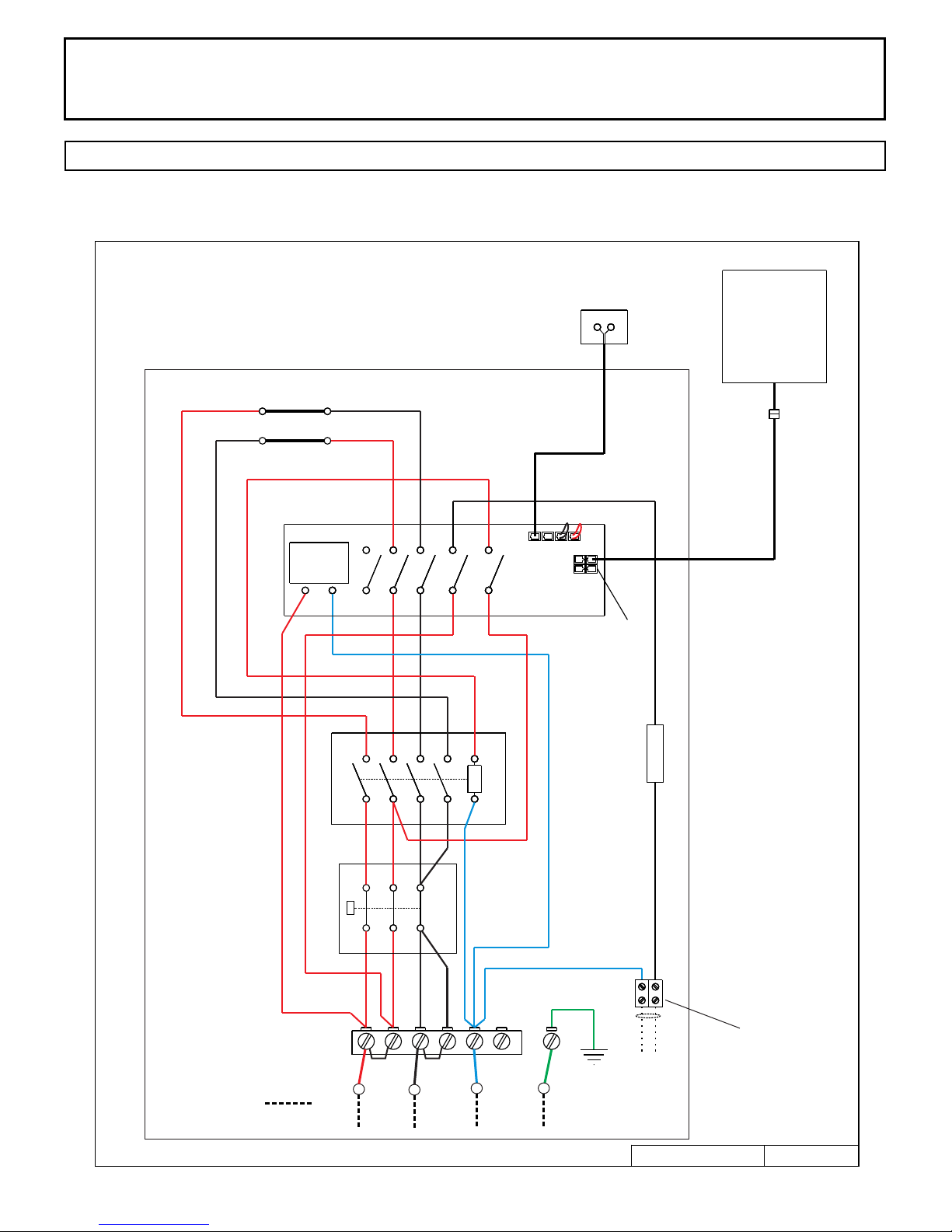
NOTE 1: Neutral is required for heater and control to operate. Light output from heater is 120 volts at 2 amps maximum.
72-0111 11-10-17 7014625 314 SKMS 1 A
DIAGRAM 2

INSTALLATION AND OPERATING INSTRUCTIONS
Page 3
SECTION 2: MOUNTING OF SAUNA HEATER
HANGING THE HEATER This heater can be installed in a corner or on a at wall.
The heater brackets are factory attached for a at wall installation. To mount the
heater in the corner reverses the brackets.
Using the template provided, drill four 9/64" holes to fasten the heater to the wall.
The screws must be threaded through the wall into a framing member or backing
board to support the heater weight. Install the two ¼" x 1 ½" hex head lag screws
(supplied with the heater) into the upper two holes. Install the two ¼" x 1" hex
head lag screws (supplied with the heater) into the lower two holes. Tighten these
screws until their heads are about 1/8" from the wall surface. Hang the heater on
the four screws. Tighten to lock the heater in place. See Diagram 1 for the heater
location details and the necessary clearances to combustible materials. Refer to
Diagram 1 for drawings and Diagram 4 for pictures.
SECTION 3: PLACING OF ROCKS (SEE DIAGRAMS #10 and 11)
The rocks supplied have been chosen to provide the best heater performance. Use of any
other type of rock may void the heaters warranty. Never operate the heater without rocks
in place! Rinse the rocks with water before placing in the heater.
Install the BWT (Bio Water Technique) tank between the two heating elements. The BWT
tank rests on the top of the elements and aligns with slot in the back heat shield (See
Diagram 11). Place the cover on the tank followed by the fragrance diffuser cup on top.
Start inserting rocks into the heater in even layers so that the heating elements remain as
vertical and evenly spaced as possible. Continue to randomly drop rocks into the heater
until you are even with the top of the heating coils. Add one more loose layer to cover up
the elements and closed portion of the BWT tank. (Do Not Cover Up the round fragrance
diffuser on top of the BWT!) The rocks must fully cover the heating elements. Attach the
rock guard with the screws provided. See Diagram #10 & 11 for rock placement.
Packing the rocks too tightly may cause the heater high limit switch to trip or the room to
heat slow.
SECTION 4: ELECTRICAL HOOK-UP
Electrical installation must be made by a licensed electrician in accordance with the
National Electrical Code and local regulations.
- NOTE: A GFCI (Ground Fault Interrupt Circuit) device is not required by ETL. A GFCI may
be installed if required by local codes but will nuisance trip during use of the product.
- CAUTION: Loose wire connections can cause heat damage to wires, terminal blocks and
other components and may void the warranty.
WARNING
Fire sprinkler systems used
inside any sauna room should
be properly rated for sauna
room temperatures.
Do not place hand or arms
over the BWT when hot.
Steam from BWT may cause
severe burns.
Do not pour chlorinated pool
or spa water on heater or in
the BWT.
Excessive water use on heater
may cause damage and void
warranty.
Electric Shock Hazard - High
voltage exists within this
equipment. There are no user
serviceable parts in this
equipment. All installation
and service to this equipment
should be performed by
qualied licensed personnel
in accordance with local and
national codes.
Remove the four screws and cover from the back the electrical access of the heater. Slowly
slide out the electrical wiring compartment. Route the wires through the holes provided in
the bottom of the heater and connect the wires to the terminal block. To determine the
correct wire size, refer to Diagram 2. Use copper supply wire only, suitable for minimum
90 degrees C. The heater must be grounded! See Diagram 6 & 8 for proper connections.
SECTION 5: TEMPERATURE SENSOR
Feed the "low voltage" sensor wire from the sensor to the sauna heater location. Sensor
wire must be routed completely separate (as per low voltage electrical wiring codes) from
any wiring carrying over 50 volts. It may be necessary to drill holes to string the wire
through the studs or ceiling joists. Route the wire to bottom of the heater and connect to
the Sensor (NTC) Port on the circuit board. Mount sensor to nished wall 3" from the
ceiling directly above the heater using two (2) screws (provided) as shown in diagrams 1,
3, 5, & 8.
72-0111 11-10-17 7014625 314 SKMS 1 A
Do not construct sauna room
so as to restrict air ow
through the bottom of the
heater.
Packing the rocks too tightly
may cause the heater high
limit switch to trip.

INSTALLATION AND OPERATING INSTRUCTIONS
Page 4
Sensor
Wire
Trend
Control
Minimum
ceiling
spacing
High
Limit
Switch
Reset
73 1/2"
DIAGRAM 3
Se n s or protec t i ve cover. L ocate
to p o f sensor 3 " f rom ceili n g
an d d irectly a b o ve of heat e r.
He a ter Inpu t Pow e r
Light Output Power
DIAGRAM 4
Mounting Heater to Flat wall or Corner.
1 5 fo o t L o w Vo lt ag e C ab le pr ov i de d w it h c on t ro l.
DIAGRAM 5
Back of
Sensor
Insert screwdriver tip here to
unsnap sensor cover from
sensor.
Note vertical orientation of
72-0111 11-10-17 7014625 314 SKMS 1 A
cover before removing.
DIAGRAM 5, continued
3" from
ceiling to top
of sensor and
centered
above the
heater.

INSTALLATION AND OPERATING INSTRUCTIONS
DIAGRAM 6
120 Volt Wiring Diagram Color Code
Piccolo Heater Models
Page 5
1217-17-1706 1.7 kW
1217-21-1706 2.1 kW
Left
Left
Element
Element
Right
Element
120 Volt
Transformer
X1 X2 X3
X4
Sauna Heater
X6 X10
X8
X5 X9
X7
X12
X11
Sensor
2 3
4 Control
Ports
Trend / A30
Control
1601-31 or
1601-31-1
120 Volt
120 Volt Connections
Field Wiring
2
Contactor
1 3
P2
P1
1 2 3
1
L1
4
P3
2
6 8 A2
5 7
Switch
High Limit
4 5
3
N
A1
6
GND
2 Amp
Breaker
H
N
354 SKMS 1 A
120 Volt
Light Output
2.0 Amp Max
10/02/17
72-0111 11-10-17 7014625 314 SKMS 1 A
INSTALLATION AND OPERATING INSTRUCTIONS
DIAGRAM 6
240 Volt Wiring Diagram Color Code
Piccolo Heater Model
Page 6
1217-35-1706 3.5 kW
Left
Left
Element
Element
Right
Element
120 Volt
Transformer
X1 X2 X3
Sauna Heater
X4
X6 X10
X8
X5 X9
X7
X12
X11
Sensor
2 3
4 Control
Ports
Trend / A30
Control
1601-31 or
1601-31-1
120 Volt
240 Volt Connections
Field Wiring
2
Contactor
1 3
P2
P1
1 2 3
1
L1
4
P3
2
L2
6 8 A2
5 7
Switch
High Limit
4 5
3
N
A1
6
GND
2 Amp
Breaker
H
N
354 SKMS 2 A
120 Volt
Light Output
2.0 Amp Max
10/02/17
72-0111 11-10-17 7014625 314 SKMS 1 A

INSTALLATION AND OPERATING INSTRUCTIONS
Version 1 2 3 4 5 6 7 8 9 10
1 hour 6 min 12 min 18 min 24 min 30 min 36 min 42 min 48 min 54 min 60 min
24 hour 2 hr 4 hr 6 hr 8 hr 10 hr 12 hr 14 hr 16 hr 18 hr 24 hr
LED
Page 7
SECTION 6: HEATER GUARD RAIL
Install a wooden heater guard to prevent the sauna bather from accidentally
touching the sauna heater. Install the heater guard rail with the dimensions shown
in Diagram 1.
SECTION 7: CONTROL INSTALLATION & OPERATION
INSTALLATION ROUGH IN: Place the control inside or outside the sauna room. If
the control is installed inside a sauna room, the top of the unit cannot be higher
than 48 inches above oor. Maximum control cable length is 50 feet.
String the provided low voltage control cable through 1” holes in the wall studs or
ceiling joists from the control location to the heater. Do not use staples to secure
the low voltage cable, it may damage the cable!
Plug the control cable into the control and TEST the control BEFORE mounting!!
After testing is complete, CLEAN the mounting surface to ensure it is free from
dust. Remove the adhesive tape from the back of the control, push any excess
cable into wall cavity and press the control to the mounting surface.
A. B. C.
A. - On/Off Light Switch
B. - Indicators - lighting, door
switch (n/a), timer and the heater
C. - On/Off Sauna Switch and fault
D.
alarms
D. - Sets the desired value
E. - Functions - Temperature, Delay
Timer, Sauna Length and Humidity
(n/a)
WARNING
Do not locate benches over
heater. Refer to Diagram 1
for minimum clearance of
ceiling above heater is
required.
Minimum clearance from
heater to wooden surfaces
(benches, side walls, heater
fence etc.) is required. Refer
to Diagram 1 for specic
information.
Mounting brackets supplied.
Provides proper clearance
from wall behind heater.
Use only copper wire of the
size and type indicated in the
Heater Specication Chart
and the temperature rating
indicated on the heater
junction box.
All heaters and controls must
be grounded per NEC to
prevent electrical shock in
case of unit failure.
E.
F. - Function buttons
Electrical outlets or
receptacle must not be
F.
CONTROL OPERATION:
TURN ON LIGHT: Press the "light bulb" icon once to turn on the light and press
again to turn off. (Usage of light control is optional)
installed in a sauna room.
A guardrail or fence is
required around the heater to
prevent burns from
SAUNA LENGTH: (Control 1601-31) Select the sauna length function by pressing
the buttons < > (F). Set the desired usage time (0–60 minutes) using the – and +
buttons. (Setting 10 equals 60 minutes)
(Control 1601-31-1) Usage time is 0-24 hours operation
(Setting 1 = 2 hours, setting 10 = 23 hours)
72-0111 11-10-17 7014625 314 SKMS 1 A
accidental contact.
INSTALLATION AND OPERATING INSTRUCTIONS
SECTION 7: OPERATION, Continued
Page 8
SET TEMPERATURE: Press function button (F). Then you can choose the desired
temperature 1–10 using buttons < and >. (Setting 10 equals highest set point.)
START HEAT IMMEDIATELY:
Start the heater on by pressing the On/Off button. The latest temperature and usage time
settings will remain preset. The On/Off indicator will glow green while heating. To add
more time after system is running, press the On/Off button twice to restart program.
When system is heating , the set temperature indicator LED will remain solid and the current
temperature indicator LED will ash. When the current temperature reaches the set value the
indicator light will stop ashing.
You may switch the system off before the usage time ends by pressing the On/Off button.
The On/Off indicator LED will go out. NOTE: The room light indicator will remain on. It will
turn off automatically after 10 minutes.
TIME DELAY START TIME: The control may be set to delay start mode to activate the
heater after a preset amount of time. Select the clock symbol using the function button
(F). Use the < and > buttons to select the amount of hours (1–10 hours) after which the
device will switch on. Activate a later start by pressing the Start button (C).
The timer symbol light will come on (in eld B) and the selected time-lapse indicator light
will start ashing. The ashing indicator measures and indicates the time leading up to the
device being switched on. When the heater starts, the control panel will automatically
show the set temperature.
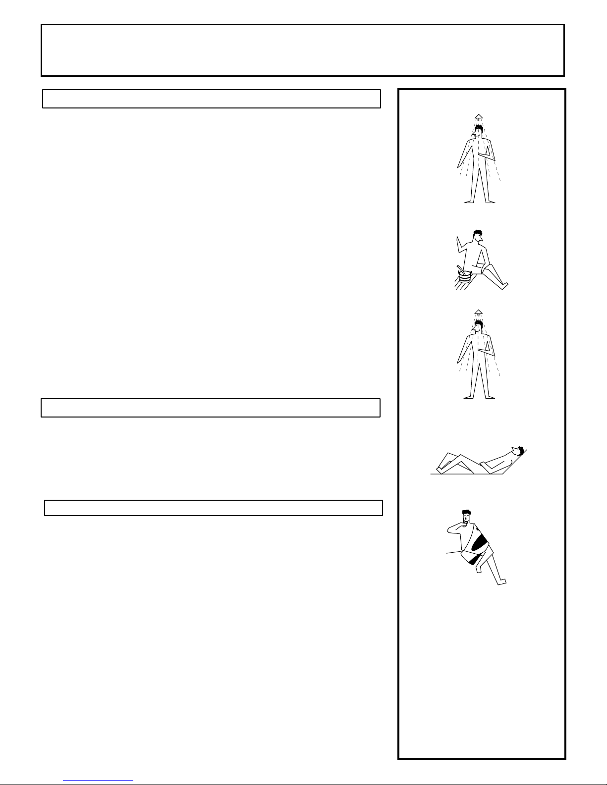
Shower
Sauna (10 - 15 min.)
SECTION 8: HIGH LIMIT CONTROL (RESET BUTTON)
The sauna heater has a built-in high limit control, which automatically turns off the heater
if the temperature inside in the sauna room rises to an abnormally high level.
To restart the heater, let the heater cool, then push the reset button on the lower back left
corner of the heater, see Diagram 3 & 8. If the high limit continually shuts off the heater,
refer to Section 16 for Troubleshooting.
SECTION 9: HOW TO TAKE A SAUNA
• When taking a sauna, allow time to relax completely.
• Remove clothing and jewelry...if required, wear a towel loosely.
• Some sauna bathers enjoy the soothing effect of steam by splashing water on the
heated sauna rocks. Use only one dipper full (approx. ½ cup) at a time and keep clear
of the steam as it rises off the rocks.
• This heater has a BWT provided and must be installed in the heater.
• Water in the BWT will add a continuous humidity to the sauna room. Additional water
can be poured onto the hot rocks at any time to boost the steam level.
• Fill tank with approximately 2 cups of fresh tap water when heater is turned on (never
use water from a pool or spa!)
• Heater can operate with BWT tank empty if user does not want constant steam.
• You may add fragrance oils to the BWT if desired.
• Do not pour chlorinated pool or spa water on the heater or corrosion damage may
result.
• After 10 minutes or when perspiration begins, leave sauna and relax in dressing area...
follow with a cool shower.
• Cooling time should equal time spent in sauna. Enter sauna room again and stay 5 or
10 minutes.
• Repeat the cycle 2 or 3 times; end with a brisk shower...rinse in cool water.
• Dress when completely dry and perspiration has stopped.
• Do not smoke, exercise or drink alcoholic beverages in the sauna room.
72-0111 11-10-17 7014625 314 SKMS 1 A
Shower or swim
Rest (10 - 15 min.)
Relax with juice or water
You liked it?
Do it once again and
you will feel great.

INSTALLATION AND OPERATING INSTRUCTIONS
Page 9
DIAGRAM 7
TYPICAL PRE-CUT WALL CONSTRUCTION
2x4" framing
1/2" wallboard
berglass insulation
foil vapor barrier
T&G soft wood
1/2" wallboard
DIAGRAM 8
Electrical Compartment Components
F
A
A. - Light Out Terminal Block
B. - Trend Control Port Connection (Suggest Upper Left Port)
C. - Sensor (NTC) Port Connection
D. - Light Fuse
E. - High Limit Reset
F. - Electrical Access Tray (Slides In and Out)
B
C
D
E
DIAGRAM 9
VENTILATION
Locate vent under
the top bench
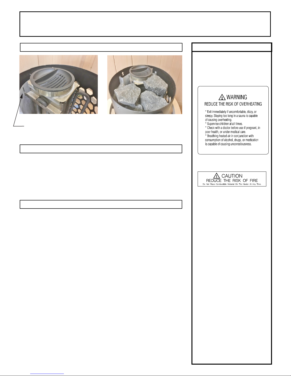
DIAGRAM 10
Rock Placement
1. Install BWT tank with rock spacer under tank.
2. Put smaller rocks in rst around the outer perimeter of the
heating elements in layers.
3. Ensure the elements are vertical and BWT is in position
while lling the heater with rocks.
4. Be sure rocks completely cover the elements.
5. Loosely cover the tops of all elements and the BWT cover
with rocks.
6. Do NOT Cover the Fragrance Diffuser with Rocks
7. Install rock grill on heater.
72-0111 11-10-17 7014625 314 SKMS 1 A
INSTALLATION AND OPERATING INSTRUCTIONS
Page 10
DIAGRAM 11
BWT tank hangs on the top of the
heating elements and aligns with
inserted tabs into back heat shield.
BWT tank, tank lid, and the fragrance
diffuser installed and the rocks placed
around the tank.
SECTION 10: WARNING PLACARDS
Three metal placards are included in the Installation Instruction Envelope
packaged with every Sauna Heater. The CAUTION placard must be attached
to the interior wall of the sauna room directly above the heater where it is
visible to the bather. The French and English WARNING placards must be
attached to the door outside of the sauna room.
WARNING
The "CAUTION" and
"WARNING" placards must be
mounted in accordance with
Section 10.
SECTION 11: ROOM CONSTRUCTION
For safety and reliability, the following rules must be addressed.
• No permanent locking or latch system is to be used on the sauna door.
• Acceptable door ttings are: magnetic catches, friction catches, spring
or gravity loaded closures. The door must always open outwards.
• No shower may be installed in a sauna room.
• No electrical receptacle shall be installed inside the sauna room.
• The enclosed WARNING: Reduce the risk of overheating … warning
plate must be mounted on or alongside the door outside the sauna room
at about eye level.
• The enclosed CAUTION: Reduce the risk of re … caution plate must be
mounted on the interior wall above the heater.
• The heater should not be operated without its container properly lled
with rocks and the rock guard in place.
• If an intercom speaker is installed, it should be away from the heater and
as close to the oor as possible.
• If a room light is installed, it should be a surface mounted bracket type.
Wall mounted lights should be about 70" above the oor. Ceiling
mounted lights should be of an approved type with a junction box that is
remote to the xture itself.
• Fire sprinkler systems installed inside any sauna room should be
properly rated for sauna room temperatures.
• Always install the heater according to these installation instructions.
For safety purpose sauna
door must open out and not
lock.
Never use a wood stain, seal
or preservative on the inside
of your sauna room.
Light xtures get very hot
during operation. Locate
light xture where it will not
be a burn hazard.
72-0111 11-10-17 7014625 314 SKMS 1 A

INSTALLATION AND OPERATING INSTRUCTIONS
Page 11
SECTION 12: VENTILATION
VENTILATION In a sauna, the air should be changed about 6 times an hour. This can be achieved by making a vent
opening (fresh air inlet) in the sauna wall directly below the heater. The air outlet must be lower than the upper benches,
as far as possible from the heater and about two feet higher than the fresh air inlet vent, See Diagram 9. It is
recommended that ventilation openings meet the requirements of UL Specication 875. The minimum opening should
be determined using one of the following formulas:
For R< 31, V ³ 9.3, For R ³ 31, V ³ 0.3R
where R = the oor area of the room in square feet and
V = the minimum vent size in square inches
SECTION 13: BWT (Bio Water Technique) Technology
The world sauna trend is moving to the higher humidity and lower temperatures. Many nd it easier to breathe, the skin
feels warm, and the humidity helps induce a sweat. This system will increase the humidity in the room allowing the air
temperature to be lower, and still feel hot.
BWT technology provides the ability to increase humidity levels in the sauna room while the heater is warming up and
during the sauna session. The continuous soft boil of water during the sauna session increases the humidity in the room
to provide a consistent feel. Additional water can be added to the rocks to provide an additional spike of humidity as
needed.
How to use BWT: Allow heater to warm up for approximately 20 minutes and add water into the tank through the side of
fragrance diffuser with slots. Add approximately 2 cups of fresh water into the tank. Do Not Use Pool or Spa Water.
Fragrance oils can be placed in the side of the fragrance diffuser without the slots. Avoid adding fragrances directly into
the water of the BWT. The oils may cause the water to foam and maybe difcult to remove the scent from the tank.
BWT tank and sleeve should always be installed in heater with rocks. Water in the tank is optional and not required if
preference is lower humidity.
SECTION 14: MAINTENANCE
The sauna, like a bathroom, should be kept clean and odor free.
Towels or mats should always be used on benches and oor as perspiration otherwise penetrates the soft wood.
Air out the sauna often by keeping the door and vents open when the sauna is not in use. Saunas that are in daily use
should be washed down at least once a week to keep them clean and the air fresh. Duckboard should be removed from
the sauna, the sauna oor mopped and dried in a conventional manner, and the duckboard thoroughly scrubbed and dried
before returning to the sauna room. The sauna heater should be wiped down occasionally with a damp cloth to remove
lint and dust. The rocks should be removed once a year for cleaning and small or crumbled rocks replaced.
To clean and remove perspiration stains, use soap or detergent in warm water, best applied with a scrub brush. Badly
soiled surfaces may require sanding. Sand paper wrapped around a wooden block works well.
Benches and supporting structure must be inspected annually for potential deterioration due to age, dry rot or abuse. Any
boards with signs of deteriorations should be replaced immediately to avoid possible injury.
BWT will accumulate hard-water scale inside the tank as the water is evaporated over time. The water scale will not
immediately affect performance. It is recommended to remove the tank from the heater and clean it when you notice a
heavy accumulation of minerals or when the rocks are changed. Simply tap on the sides of the tank to loosen the scale
and then dump into a waste basket. If stubborn scale accumulation remains, you may use any commercially available
de-scaling product to remove built-up hard water scale. Follow up with a fresh water rinse before putting BWT back into
the heater.
72-0111 11-10-17 7014625 314 SKMS 1 A
INSTALLATION AND OPERATING INSTRUCTIONS
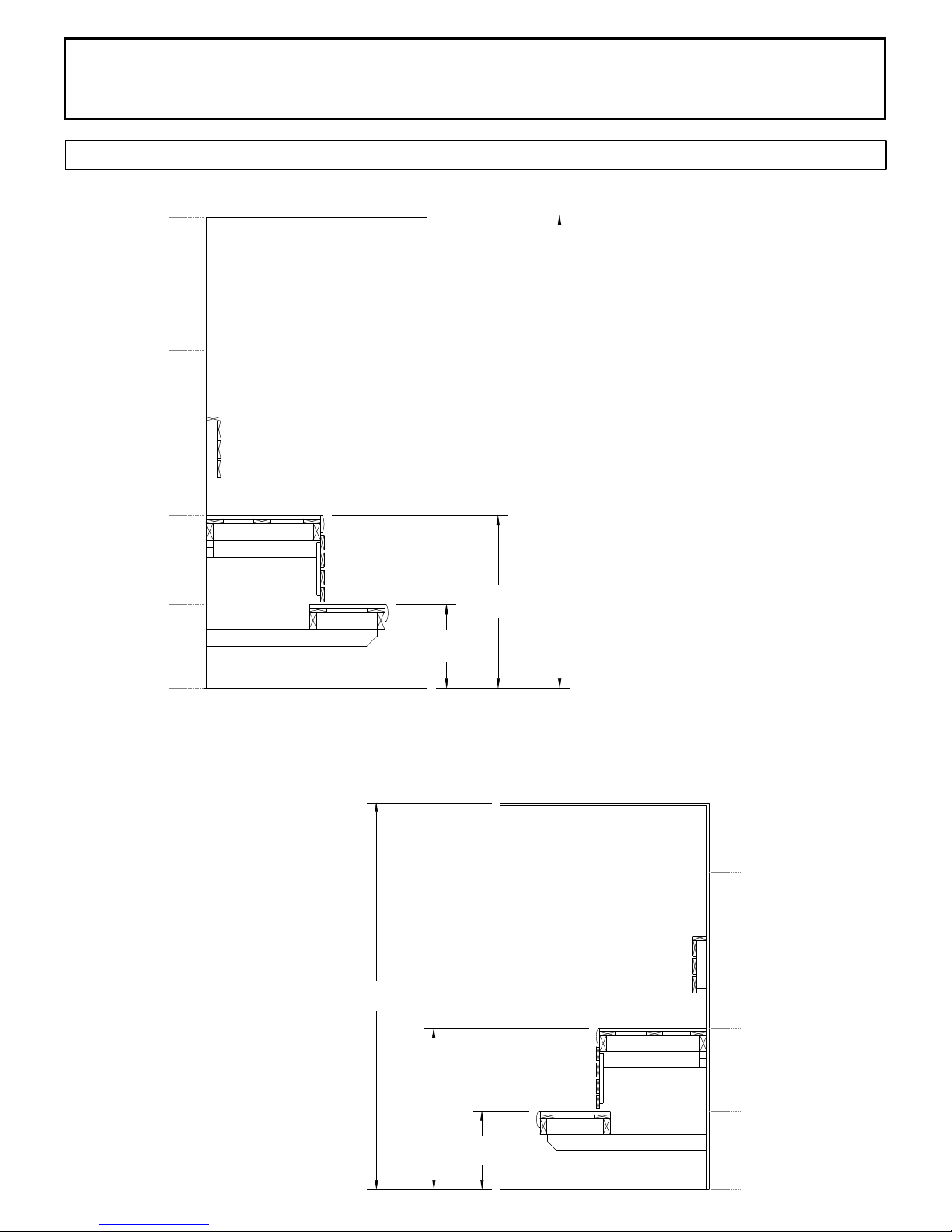
DIAGRAM 12: ROOM TEMPERATURES
190° F
Ceiling
Page 12
Non-Typical Ceiling Height
140° F
125° F
95° F
85° F
Head Height
Upper Bench
Bench Support
Lower Bench
Bench Support
Floor
17"
35"
Notes:
96"
Temperatures vary in a sauna room by
height and distance from heater.
Ventilation will help reduce it but will not
eliminate temperature variations.
The hottest part of the room is always at
the ceiling directly above the sauna
heater and should not exceed 194°F
(90°C).
Air temperature will be 15°F to 25°F
lower on the opposite side of the room
from the heater close to the ceiling.
The temperatures in the elevated view
are general numbers. Each sauna room
is different due to construction variations
and ventilation.
Typical Ceiling Height
72-0111 11-10-17 7014625 314 SKMS 1 A
84"
35"
17"
Ceiling
Head Height
Upper
Bench
Lower Bench
Floor
190° F
160° F
140° F
100° F
85° F
INSTALLATION AND OPERATING INSTRUCTIONS
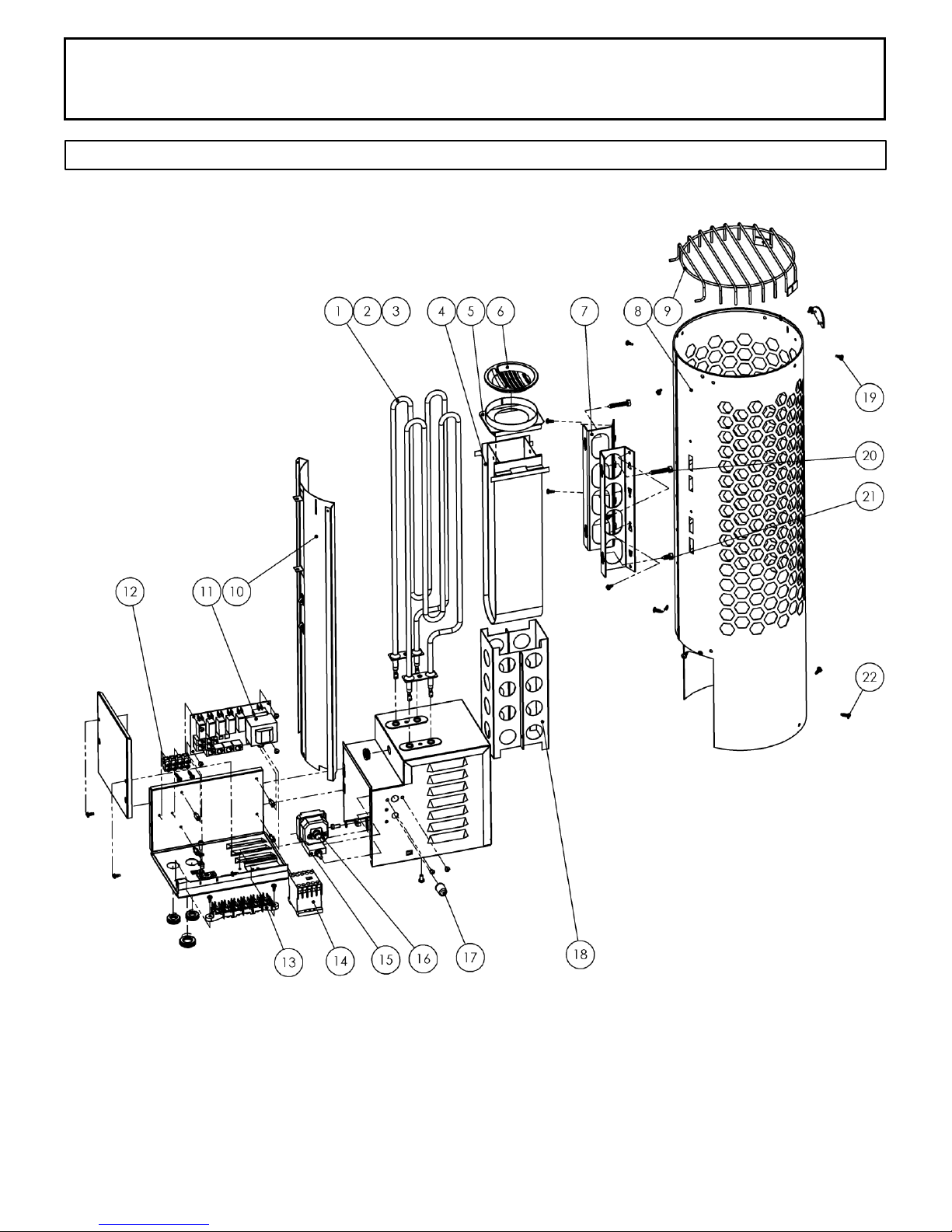
SECTION 15: REPLACEMENT PARTS
Page 13
72-0111 11-10-17 7014625 314 SKMS 1 A

INSTALLATION AND OPERATING INSTRUCTIONS
ID # THI Part Number Description Qty
1 3001-761 Element,850W, 120V, SEPC-232 2
2 3001-762 Element, 1050W, 120V, SEPC-233 2
3 3001-763 Element, 1750W,240V,SEPC-234 2
4 8100-479 BWT Tank 1
5 4009-001 BWT Tank Cover 1
6 8221-06 BWT Herb cup 1
7 8100-485 Heater wall mount bracket 2
8 8012-524 Shroud, outer, black 1
9 8019-514 Rock Grill 1
10 8012-525 Shroud,Galv,Heat Sheild / High Limit,Internal 1
11 3229-002 PCA, Low, 120v 1
12 2100-207 Terminal strip, 4 position 1
13 2100-551 Terminal,Block,6-Position 1
14 3131-516 Contactor, LC1K09004G7, 120v 1
15 3100-593 Schurter Fuse, 2amp 1
16 3100-509 High Limit Switch, 150°C 1
17 2137-30 Cap,Clear Silicone,(for reset Light Fuse) 1
18 8007-001 Internal Tubular Sleeve for BWT 1
19 N/A Pan Head, blunt tip, M2, Black Screw
20 N/A 1/4-20 x 1-1/2" lag bolt 2
21 N/A 1/4-20 x 3/4" lag bolt 2
22 N/A Screw,PH,Black,Blunt,Washer Type, M2
7200-008 Wood htr guard 1
8201-046 Bracket,Wood Heater Guard, Black 3
9301-158 Sensor, Olet 29 with cable 1
2990-103 Rocks, medium, 50lb/23kg 1
SECTION 15: REPLACEMENT PARTS
Page 14
72-0111 11-10-17 7014625 314 SKMS 1 A

INSTALLATION AND OPERATING INSTRUCTIONS
Page 15
SECTION 16: TROUBLESHOOTING
Control will Run but No Heat - Press the (reset) high limit switch on the back right side of heater.
Slow Heat Time or High Limit Tripping - Check rock placement, they will break down over time and reduce the air
ow in the heater. Refer to Diagram 10 for proper rock installation. Discard all rocks under the size of 2" pieces. Call
the number below to order more rocks if needed.
In the event of a fault occurring in the heater system (control panel, temperature sensor, etc.), the LED On/Off
indicator will ash red on the control panel.
The fault error code will be displayed with a constant LED light or a ashing LED light under numbers 1-10. See the
list below for fault codes.
Constant LED Fault Code (ones marked with “n/a” are not in use):
LED Flashes Red
during a fault
1 Temperature sensor not connected or it is faulty
2 n/a
3 Heater circuit board overheated
4 One or more relay defective
5 n/a
6 n/a
7 Temperature sensor
8 n/a
9 Clock disconnected
10 Power supply to clock disconnected
Flashing LED Fault Code
1 n/a
2 n/a
3 n/a
4 Temperature sensor faulty
5 Problem with device connection
6 n/a
7 n/a
8 Too many temperature sensors connected
9 n/a
10 n/a
For troubleshooting or service questions call 1-888-780-4427 and ask to speak with service. Prior to calling, please
have the Model and Type number available. You may also email us at
72-0111 11-10-17 7014625 314 SKMS 1 A
1 - 10 Indicates the
fault code
techsupport@tyloheloinc.com
 Loading...