

Piazzetta IL 65/54, IL 65/49, IL 75/58, IL 75/64 Installation, Use And Maintenance Instructions
Page 1
Page 2

Dear Customer,
Thank you for having chosen one of our products, which is the result of years of experience and continuous research aimed at making a
superior product in terms of safety, reliability and performance.
T
his booklet contains information and advice for safe and efficient use of your product.
D
T2010001-01
See the guarantee certificate enclosed with the product for the terms, limitations and exclusions.
In line with its policy of constant product improvement and renewal, the manufacturer may make changes without notice.
This document is the property of Gruppo Piazzetta S.p.A.; no part of it may be disclosed to third parties without the written permission
of Gruppo Piazzetta S.p.A.
All rights reserved by Gruppo Piazzetta S.p.A..
• This instruction booklet has been prepared by the manufacturer
and is an integral part of the product. In the event of sale or relocation of the product make sure this booklet accompanies it, since
the information contained in it is addressed to the purchaser and
to anyone involved in the installation, use and maintenance of the
product.
• Read the instructions and the technical information contained in
this booklet carefully before proceeding with installation, use or
any repairs.
• The observance of the instructions and technical information in
this instruction booklet guarantees the safety of persons and property; it also ensures more efficient operation and an increased lifespan.
• Gruppo Piazzetta S.p.A. cannot be held responsible for damage or
injury due to failure to comply with the instructions for installation, use and maintenance given in this booklet, or due to unauthorised alterations or to the use of other than original spare
parts.
• Appliance installation and use must conform with the manufacturer’s instructions as well as with European and national legislation and local regulations.
• The wall against which the product is to be placed must not be of
wood or any other flammable material. For correct installation it
is also important to maintain safety distances (refer to the section
entitled “MINIMUM SAFETY DISTANCES”).
• Prior to completing installation of the surround, light the stove
and when it has heated up check that the grate and that the flue
connection is correct.
• Check that the floor where the product is to be installed is perfectly level.
• Do not fix the heater unit in any way whatsoever, but simply place
it next to the surround.
• When handling the steel parts of the surround or the ceramic
parts it is advisable to use clean cotton gloves to avoid leaving fingerprints that are difficult to remove at first time of cleaning
• The fireplace must be assembled by two persons.
• This appliance has been designed solely for heating. It is not recommended for cooking foods.
• Stop using the product in the event of fault or malfunctioning.
• The product you have purchased may differ slightly from the one
illustrated in this booklet since the pictures are only given as an
indication and not an exact portrayal.
UNI EN 832 . . . . . . . . . . . . . . . . . . . . . . . .Thermal performance of buildings - Calculation of energy use for heating
UNI EN 13229 . . . . . . . . . . . . . . . . . . . . . .Inset appliances including open fires fired by solid fuels - Requirements and test methods
UNI 10683:2005 . . . . . . . . . . . . . . . . . . . . .Heating appliances fired by wood or other solid biofuels - Installation requirements
UNI EN 13384 . . . . . . . . . . . . . . . . . . . . . .Chimneys - Thermal and fluid dynamic calculation methods
UNI 7129 . . . . . . . . . . . . . . . . . . . . . . . . . .Gas plants for domestic use fed by network distribution
UNI 10847 . . . . . . . . . . . . . . . . . . . . . . . . .Chimneys for generators feeded with liquid and solid flues - Maintenance and inspection
EN 1856-1 . . . . . . . . . . . . . . . . . . . . . . . . .Chimneys - Requirements for metal chimneys - Part 1: System chimney products
EN 1856-2 . . . . . . . . . . . . . . . . . . . . . . . . .Chimneys - Requirements for metal chimneys - Part 2: Metal liners and connecting flue pipes
UNI EN 1443 . . . . . . . . . . . . . . . . . . . . . . .Chimneys – General requirements
DIN 18 895 . . . . . . . . . . . . . . . . . . . . . . . . .Fireplaces
DIN 51731 class of measurement HP2 . .Fuels
IMPORTANT INFORMATION
D
T2010139-00
REFERENCE STANDARDS
DT2010140-02
H07023830 / DT2000612 - Rev. 01
32
English
Page 3

English
INDEX
DT2010187-01
SECTION TITLE . . . . . . . . . . . . . . . . . . . . . . . . . . . . . . . . . . . . . . . . . . . . . . . . . .PAGE
1.0 GENERAL RULES . . . . . . . . . . . . . . . . . . . . . . . . . . . . . . . . . . . . . . . . . . .34
1.1 SINGLE FLUEWAY OR CHIMNEY . . . . . . . . . . . . . . . . . . . . . . . . . . . . . . .35
1.2 SOOT INSPECTION . . . . . . . . . . . . . . . . . . . . . . . . . . . . . . . . . . . . . . . . . .35
1.3 CHIMNEY STACK . . . . . . . . . . . . . . . . . . . . . . . . . . . . . . . . . . . . . . . . . . .36
1
.4 FRESH AIR INTAKE . . . . . . . . . . . . . . . . . . . . . . . . . . . . . . . . . . . . . . . . . .37
1.5 INSTALLATION ENVIRONMENT . . . . . . . . . . . . . . . . . . . . . . . . . . . . . . . .38
1.6 CAPACITY LOAD OF THE FLOOR . . . . . . . . . . . . . . . . . . . . . . . . . . . . . . .38
1.7 HEATING CAPACITY . . . . . . . . . . . . . . . . . . . . . . . . . . . . . . . . . . . . . . . . .38
1.8 SUITABLE HEAT INSULATING MATERIALS . . . . . . . . . . . . . . . . . . . . . . . .39
1.9 MINIMUM SAFETY DISTANCES . . . . . . . . . . . . . . . . . . . . . . . . . . . . . . . .39
1.10 CONNECTION TO THE FLUEWAY . . . . . . . . . . . . . . . . . . . . . . . . . . . . . . .40
1.11 LINING WALL . . . . . . . . . . . . . . . . . . . . . . . . . . . . . . . . . . . . . . . . . . . . . .41
1.12 HOOD GRILLE . . . . . . . . . . . . . . . . . . . . . . . . . . . . . . . . . . . . . . . . . . . . . .41
1.13 WOOD MANTEL PROTECTION . . . . . . . . . . . . . . . . . . . . . . . . . . . . . . . . .41
1.14 PREVENTION OF DOMESTIC FIRES . . . . . . . . . . . . . . . . . . . . . . . . . . . . .42
2.0 TECHNICAL DATA AND SPECIFICATIONS . . . . . . . . . . . . . . . . . . . . . . . . .43
2.1 DESCRIPTION OF THE APPLIANCE . . . . . . . . . . . . . . . . . . . . . . . . . . . . . .43
2.2 ACCESSORIES AND EQUIPMENT . . . . . . . . . . . . . . . . . . . . . . . . . . . . . . .45
2.3 FEATURES . . . . . . . . . . . . . . . . . . . . . . . . . . . . . . . . . . . . . . . . . . . . . . . . .45
2.4 PRODUCT IDENTIFICATION DATA . . . . . . . . . . . . . . . . . . . . . . . . . . . . . . .45
2.5 TECHNICAL DATA . . . . . . . . . . . . . . . . . . . . . . . . . . . . . . . . . . . . . . . . . . .46
2.6 DIMENSION IL 65/49 . . . . . . . . . . . . . . . . . . . . . . . . . . . . . . . . . . . . . . . .47
2.7 DIMENSION IL 65/54 . . . . . . . . . . . . . . . . . . . . . . . . . . . . . . . . . . . . . . . .47
2.8 DIMENSION IL 75/58 . . . . . . . . . . . . . . . . . . . . . . . . . . . . . . . . . . . . . . . .47
2.9 DIMENSION IL 75/64 . . . . . . . . . . . . . . . . . . . . . . . . . . . . . . . . . . . . . . . .47
3.0 INSTALLATION . . . . . . . . . . . . . . . . . . . . . . . . . . . . . . . . . . . . . . . . . . . . .48
3.1 PREPARING FIREPLACE INSERTS . . . . . . . . . . . . . . . . . . . . . . . . . . . . . .48
3.2 BEFORE INSTALLING THE INSERT . . . . . . . . . . . . . . . . . . . . . . . . . . . . .48
3.3 INSTALLATION . . . . . . . . . . . . . . . . . . . . . . . . . . . . . . . . . . . . . . . . . . . . .48
3.4 ADJUSTING THE FLUE GAS/SMOKE DAMPER . . . . . . . . . . . . . . . . . . . . .49
4.0 VENTILATION . . . . . . . . . . . . . . . . . . . . . . . . . . . . . . . . . . . . . . . . . . . . . .50
4.1 FAN SPECIFICATIONS . . . . . . . . . . . . . . . . . . . . . . . . . . . . . . . . . . . . . . . .50
4.2 USE OF THE FANS . . . . . . . . . . . . . . . . . . . . . . . . . . . . . . . . . . . . . . . . . . .50
4.3 FAN MAINTENANCE . . . . . . . . . . . . . . . . . . . . . . . . . . . . . . . . . . . . . . . . .50
4.4 REMOVING THE FAN BOX . . . . . . . . . . . . . . . . . . . . . . . . . . . . . . . . . . . . .51
4.5 FAN WIRING DIAGRAM . . . . . . . . . . . . . . . . . . . . . . . . . . . . . . . . . . . . . .51
5.0 USE . . . . . . . . . . . . . . . . . . . . . . . . . . . . . . . . . . . . . . . . . . . . . . . . . . . . . .52
5.1 FUEL . . . . . . . . . . . . . . . . . . . . . . . . . . . . . . . . . . . . . . . . . . . . . . . . . . . . .52
5.2 COMBUSTION AIR REGULATION . . . . . . . . . . . . . . . . . . . . . . . . . . . . . . .53
5.4 LIGHTING FOR THE FIRST TIME . . . . . . . . . . . . . . . . . . . . . . . . . . . . . . . .54
5.5 LIGHTING . . . . . . . . . . . . . . . . . . . . . . . . . . . . . . . . . . . . . . . . . . . . . . . . .54
5.6 OPENING THE DOOR . . . . . . . . . . . . . . . . . . . . . . . . . . . . . . . . . . . . . . . .55
5.6 NIGHT TIME OPERATION AT MINIMUM . . . . . . . . . . . . . . . . . . . . . . . . . .55
5.7 OPERATION UNDER ADVERSE WEATHER CONDITIONS . . . . . . . . . . . . .55
5.8 OVERHEATING AND EXTINGUISHING . . . . . . . . . . . . . . . . . . . . . . . . . . . .55
6.0 MAINTENANCE . . . . . . . . . . . . . . . . . . . . . . . . . . . . . . . . . . . . . . . . . . . . .56
6.1 PERIODIC CONTROL . . . . . . . . . . . . . . . . . . . . . . . . . . . . . . . . . . . . . . . . .56
6.2 CLEANING THE PAINTED METAL PARTS . . . . . . . . . . . . . . . . . . . . . . . . .56
6.3 CLEANING THE GLASS (DAILY) . . . . . . . . . . . . . . . . . . . . . . . . . . . . . . . .56
6.4 CLEANING THE GRATE AND THE ASH TRAY DRAWER . . . . . . . . . . . . . . .57
6.5 DISPOSAL OF ASHES . . . . . . . . . . . . . . . . . . . . . . . . . . . . . . . . . . . . . . . .57
6.6 CLEANING ALUKER
®
. . . . . . . . . . . . . . . . . . . . . . . . . . . . . . . . . . . . . . . .57
6.7 SEAL CONTROL . . . . . . . . . . . . . . . . . . . . . . . . . . . . . . . . . . . . . . . . . . . .57
6.8 REMOVING THE ALUKER INTERIOR AND GRATE . . . . . . . . . . . . . . . . . . .58
6.9 SHUTTING DOWN . . . . . . . . . . . . . . . . . . . . . . . . . . . . . . . . . . . . . . . . . . .59
7.0 TROUBLESHOOTING . . . . . . . . . . . . . . . . . . . . . . . . . . . . . . . . . . . . . . . .60
H07023830 / DT2000612 - Rev. 01
33
English
This booklet code H07023830 / DT2000612 - Rev. 01 - (08/2010) comprises 64 pages.
Page 4
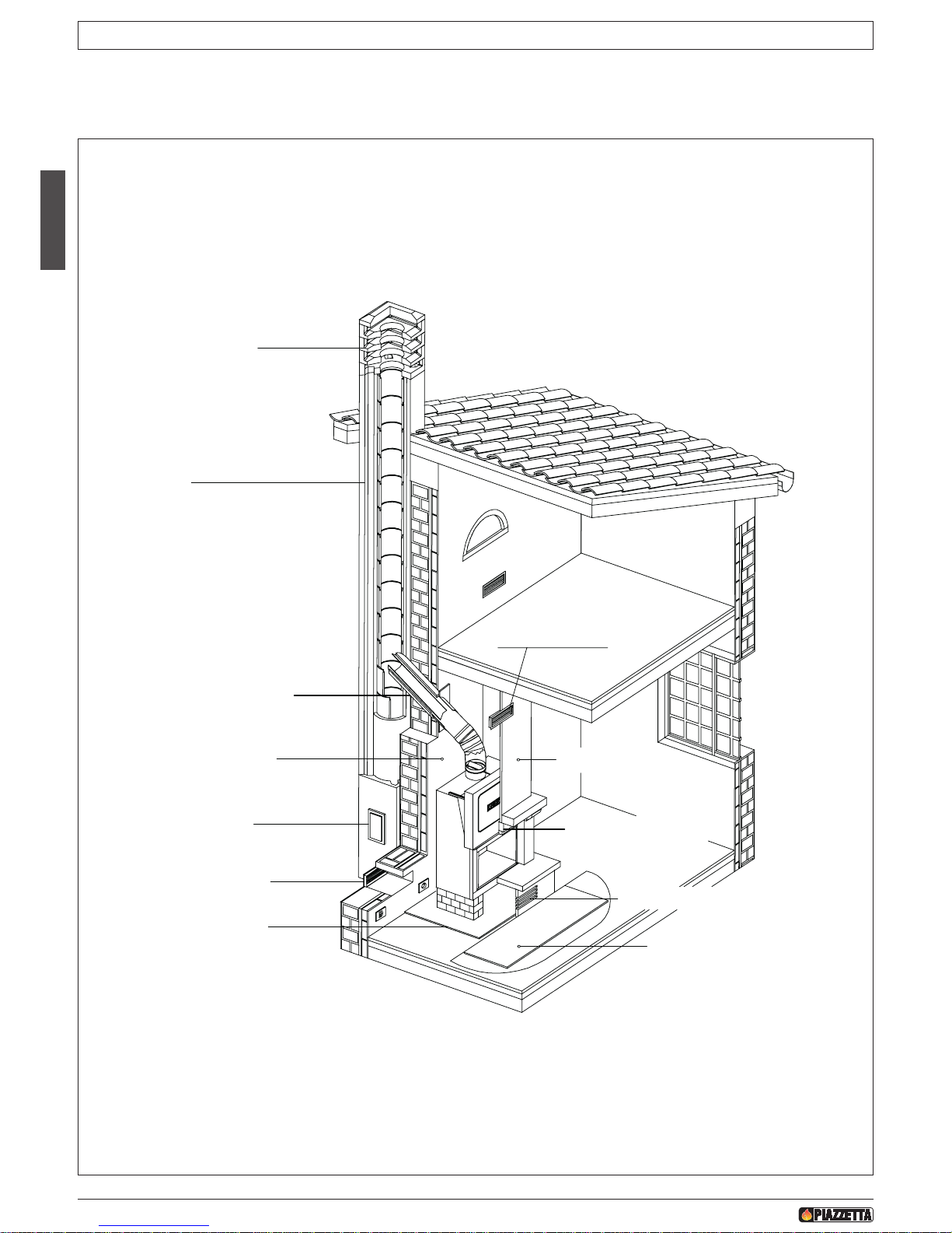
1.0 GENERAL RULES
DT2010779-02
Before proceeding with installation, choose the most suitable position for your fireplace according to the indications given in the paragraph
“MINIMUM SAFETY DISTANCES” and to all the indications below.
DT2031171-00
SOOT REMOVAL
INSPECTION HOLE
CHIMNEY STACK
FLUE
CONNECTION TO FLUE
SAFETY DISTANCES
CHECK OF FLOOR
LOAD-BEARING CAPACITY
HOOD GRILLE
OUTER HOOD
PROTECTION FOR
ORNAMENTAL LEDGE
FIXED OPENING
FLOOR PROTECTION
FRESH AIR INTAKE
F
ig. 1
H07023830 / DT2000612 - Rev. 01
34
English
Page 5
English
DT2010169-00
1.1 SINGLE FLUEWAY OR CHIMNEY
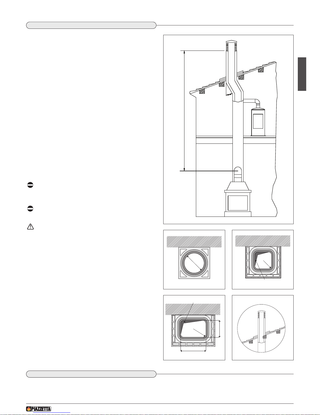
Every appliance must have a vertical flue pipe operating by natural
draught to discharge the combustion gases outdoors.
The flue must:
- comply with regulations in force in the place of installation of the
appliance;
- be tight to the products of combustion, waterproof, suitably
i
nsulated, made with materials resistant to the corrosion of the
gases and to stress;
- be connected to just one stove, fireplace or extraction hood;
- be properly sized, with constant free internal section, equal to or
greater than the diameter of the flue pipe of the stove and at least
3.5 m in length;
- be mainly in a vertical position with a deflection from the axis of no
more than 45° (Fig. 2);
- be at a suitable distance from combustible or flammable materials,
ensured by an air gap or suitable insulating material;
- be of uniform internal section, preferably round. Square or
rectangular sections must have rounded corners with a radius of at
least 20 mm and a maximum ratio between the sides of 1.5
(Fig. 3-4-5);
- the walls must be smooth if possible and without narrowing. Bends
must be regular and without discontinuity (Fig. 6).
It is forbidden to make fixed or mobile apertures on the flue
pipe to connect appliances other than the one to which it is
already connected.
It is forbidden to pass other air ducts or service pipes inside
the flue pipe, however large it is.
If the flue pipe is an incorrect size or installed other than in
compliance with the above instructions, Gruppo Piazzetta
S.p.A. cannot be held liable for malfunctioning of the product,
damage to property or injury to persons or animals.
DT2010031-01
1.2 SOOT INSPECTION
We recommend that the flue must have a chamber for collecting solid matter and any condensate located below the connection and which
may be easily inspected by means of an airtight door. (Fig.1)
D
T2030258-00
DT2030050-00
Fig. 2
Fig. 3
MAX 45°
NO
X
MINIMUM 3,5 M
Ø
DT2030188-00
Fig. 4
R (
min
.
2
0
)
D
epos
i
t
of
c
reos
ot
e
DT2030189-00
Fig. 5
P
R
(m
in.
20)
L (<_ 1,5 x P)
Deposit of creosote
DT2030190-00
Fig. 6
NO
H07023830 / DT2000612 - Rev. 01
35
English
Page 6
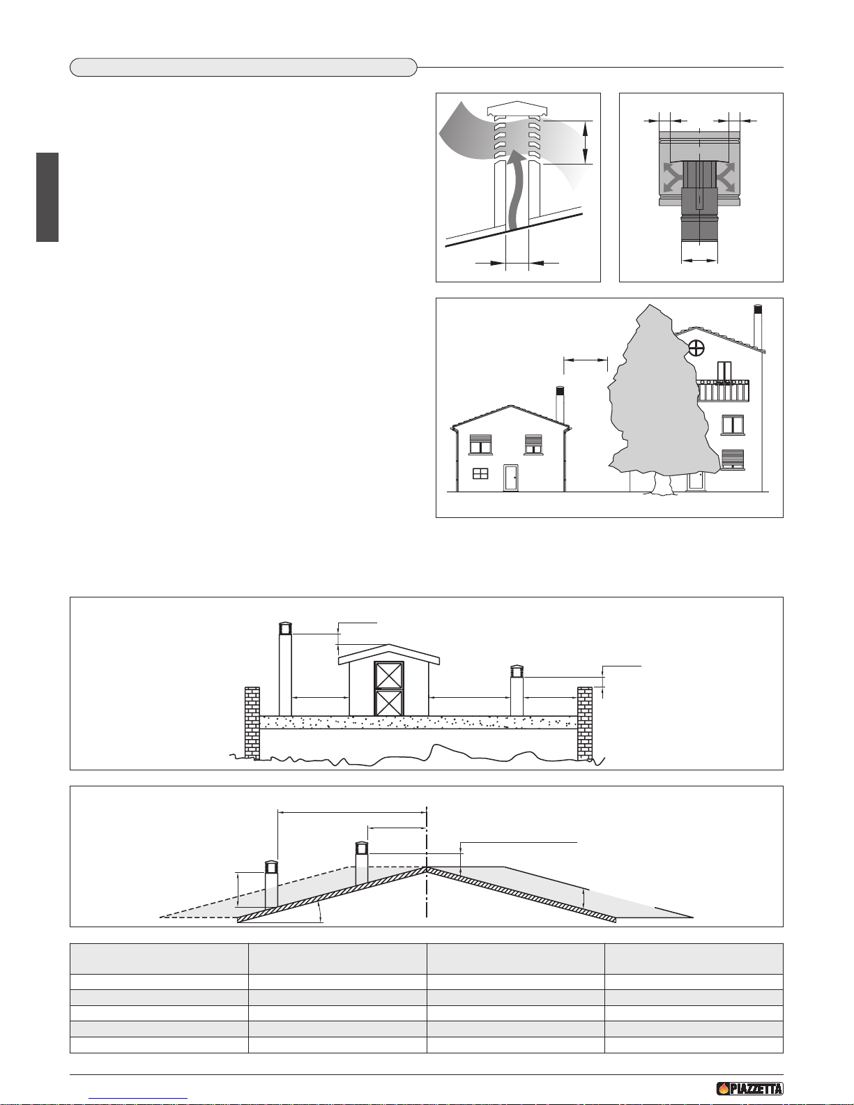
The chimney stack is a device fitted on the top of the chimney that is
designed to aid dispersion of the products of combustion in the
a
tmosphere.
The chimney stack must comply with the following requirements:
- it must have an internal section and shape the same as the flue (A);
- it must have a useful outlet section (B) of not less than twice that of
the flue (A);
-
the part of the chimney that emerges from the roof or remains in
contact with the outside (e.g. in the case of a flat roof), must be
covered with brick or tile elements and in any case well insulated;
- It must be built in such a way as to prevent the penetration of rain,
snow and foreign matter into the flue and to ensure that in the event
of winds from all directions and angle, discharge of the combustion
products is assured (chimney stack with down-draught cowl).
Recommended distances for correct chimney operation.
To ensure trouble-free operation of the chimney and allow correct
dilution of the products of combustion in the air, the chimney stack
must be installed at the distances given below:
- 6-8 metres from any buildings or other obstacles that are higher
than the chimney stack;
- 50 centimetres higher than any obstacles located at a distance less
than 5 metres;
- outside the reflux area. The size and shape of this area differ
according to the angle of inclination of the roof and it is therefore
necessary to adopt the minimum heights shown below.
Example: Check the slope of the roof (column α), and the
anticipated distance of the chimney stack from the axis of the ridge (column A); if the distance is greater than “A” the height of the chimney
stack may be read in (column H); if the distance is less than “A” the chimney stack must rise above the ridge by 0.5 metres.
6
-8 m
A
B*
* B it is twice
of to A
A
BB
FLAT ROOF
0.50 m
0.50 m
over 5 m
5 m or less 5 m or less
FLAT ROOF
SLOPING ROOF
0.50 m
0.50 m
0.50 m above the ridge
height of reflux
area Z
ridge axis
distance more than A
α
H min.
distance
min. than A
over 5 m
5 m or less 5 m or less
Pitch of the roof
Horizontal width of reflux
area from ridge axis
Minimum height of
outlet from roof
Height of reflux area
αα
A H minimo Z
15° 1,85 m 1,00 m 0,50 m
30° 1,50 m 1,30 m 0,80 m
45° 1,30 m 2,00 m 1,50 m
60° 1,20 m 2,60 m 2,10 m
Fig. 7 Fig. 8
Fig. 9
Fig. 10
Fig. 11
DT2030051-00
D
T2030052-00
DT2030053-00
DT2030192-00
DT2030191-00
1.3 CHIMNEY STACK
DT2010025-03
H07023830 / DT2000612 - Rev. 01
36
English
Page 7
English
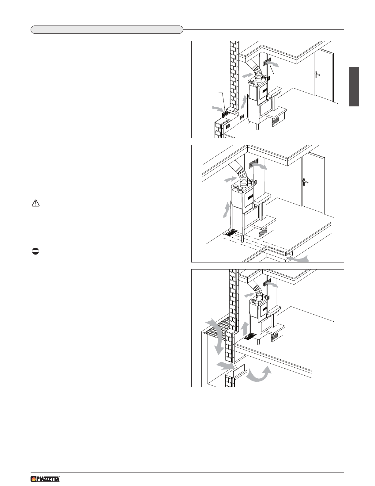
To ensure trouble-free operation the stove/fireplace must have the
necessary air available for combustion and this is provided through
t
he fresh air intake.
The fresh air intake must:
- have a total free cross section at least equal to the size given in the
paragraph “TECHNICAL DATA”;
-
be protected by a grille or suitable guard provided it does not
reduce the minimum recommended section;
- be in a position whereby it cannot be obstructed.
The airflow necessary for the fire may be obtained in different ways:
- through a fresh air intake direct into the room of installation (it is
advisable to place the air intake behind the hearth so that the air
warms up before flowing into the room through the canopy grille);
- with ducting through pipes direct to the room of installation,
increasing the recommended minimum free cross section by at
least 15%;
- from an adjacent room to the place of installation provided this air
flows freely through permanent apertures communicating with the
outside.
The adjacent room from which air is taken must not have a
low pressure compared to the exterior due to a counter
draught caused by the presence in that room of another
appliance in use or of a suction device.
The permanent apertures in the adjacent room must comply
with the requirements given above.
Combustion air must not be taken from adjacent rooms used
as a garage or a combustible materials store or for activities
posing a fire hazard.
1.4 FRESH AIR INTAKE
DT2010170-01
H07023830 / DT2000612 - Rev. 01
37
English
Fig. 13
D
T2030260-01
Fresh air
intake
Canopy
grille
Fig. 12
D
T2030259-01
Fig. 14
DT2030261-01
Page 8
DT2010033-01
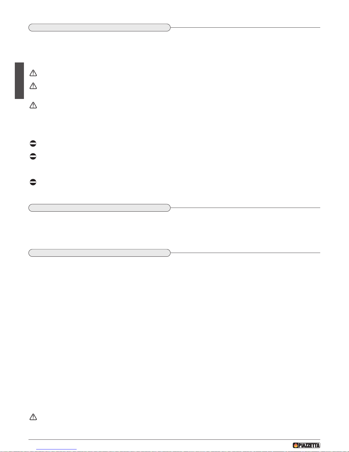
1.5 INSTALLATION ENVIRONMENT
The appliance should be installed in a location which allows safe and convenient use as well as easy maintenance. If the product being
installed requires an electrical socket, the room must also be provided with an earthed power supply in accordance with current regulations.
The room where the appliance is to be installed must comply with the following requirements:
they must not be used as a garage, store for combustible material or for activities with a risk of fire.
T
hey must not be in a vacuum in relation to the outside environment due to the effect of contrary draught caused by the presence
in the room where the fi replace is installed of another appliance or an extractor device.
Do not use two stoves, a fireplace and a stove, a stove and a wood-fired cooking range, etc. in the same environment, since the
draught of one could affect the draught of the other.
- Devices suitable for cooking food with relative hoods without an extractor fan may only be used in kitchens.
- Gas appliances of type C are allowed (refer to current legislation and regulations in the place of installation)
Gas appliances of type B are not allowed (refer to current legislation and regulations in the place of installation)
The stove or fireplace must not be used simultaneously with collective type ventilation ducts with or without extractor fan, other
devices or other appliances such as: forced ventilation systems or other heating systems using ventilation to change the air. Such
systems could cause a vacuum in the environment of installation even if installed in adjoining or communicating rooms.
The stove or fireplace must not be used: in stairwells except in buildings with no more than two apartments; in corridors for
common use; in bedrooms; in bathrooms or shower-rooms.
D
T2010171-00
1.6 CAPACITY LOAD OF THE FLOOR
Check the load-bearing capacity of the floor by adding together: the weight of the protections (lining walls), insulating materials, surround
(given in the surround instruction booklet) and the stove (given in the paragraph “TECHNICAL DATA”).
If the floor has an unsuitable load-bearing capacity, take adequate countermeasures.
DT2010130-01
1.7 HEATING CAPACITY
Check the heating capacity of the appliance by comparing the rated power given in the paragraph
“TECHNICAL DATA”
with the power required
by the environment to be heated.
The energy requirement may be calculated approximately by multiplying the square metres of area by the height of the ceiling; the result is
then multiplied by a coefficient, which depends on the degree of insulation of the building, that is, on internal and external factors of the
dwelling:
a) Internal factors: type of window and door frames, thickness of the insulation and walls, type of building materials, presence of stairwells,
walls with extensive glazing, high ceilings, position of the rooms to be heated in relation to other adjacent heated or unheated rooms, …
b) External factors: geographical position, average outdoor temperature, exposure, wind speed, latitude, altitude, …
Example of approximate calculation of the energy requirement to heat a fixed volume to 18/20° C:
The coefficient that is normally used is determined according to the real conditions as they occur case by case.
- From 0.04 to 0.05 kW per cubic metre in a well insulated environment
- From 0.05 to 0.06 kW per cubic metre in a poorly insulated environment
3 rooms measuring 20m2 X (H ceiling) 2.7m = 162 m
3
(volume)
In an environment with a good degree of insulation, an average value (coefficient) of 0.045 kW may be taken
162 (volume) X 0.045 (kW) = 7.3 kW necessary (6300 kcal/h)
Conversion 1kW = 860 kcal/h
Consult a heating technician or engineer for a correct check and calculation of the requirement of the environments to be heated
(see “REFERENCE STANDARDS”).
H07023830 / DT2000612 - Rev. 01
38
English
Page 9
English
DT2010173-01
1.8 SUITABLE HEAT INSULATING MATERIALS
Type of suitable heat insulating materials.
Material: mineral fibre; ceramic fibre; rock wool.
F
orm: sheets; mat; shells.
Specifications: specific weight of at least 245 kg/m³ with working temperature limit of at least 1000°C.
Thermal conductivity λ (400°C) ≤ 0.1 W/mK
Thickness: as shown in the figures in the paragraph “MINIMUM SAFETY DISTANCES”.
I
f the insulating material is not lining the walls, it must be fixed all over the surface of the walls with anchorage points every
30cm.
Material coded “AGI Q132” or “DIN 18895” is allowed for heat insulation.
D
T2011906-00
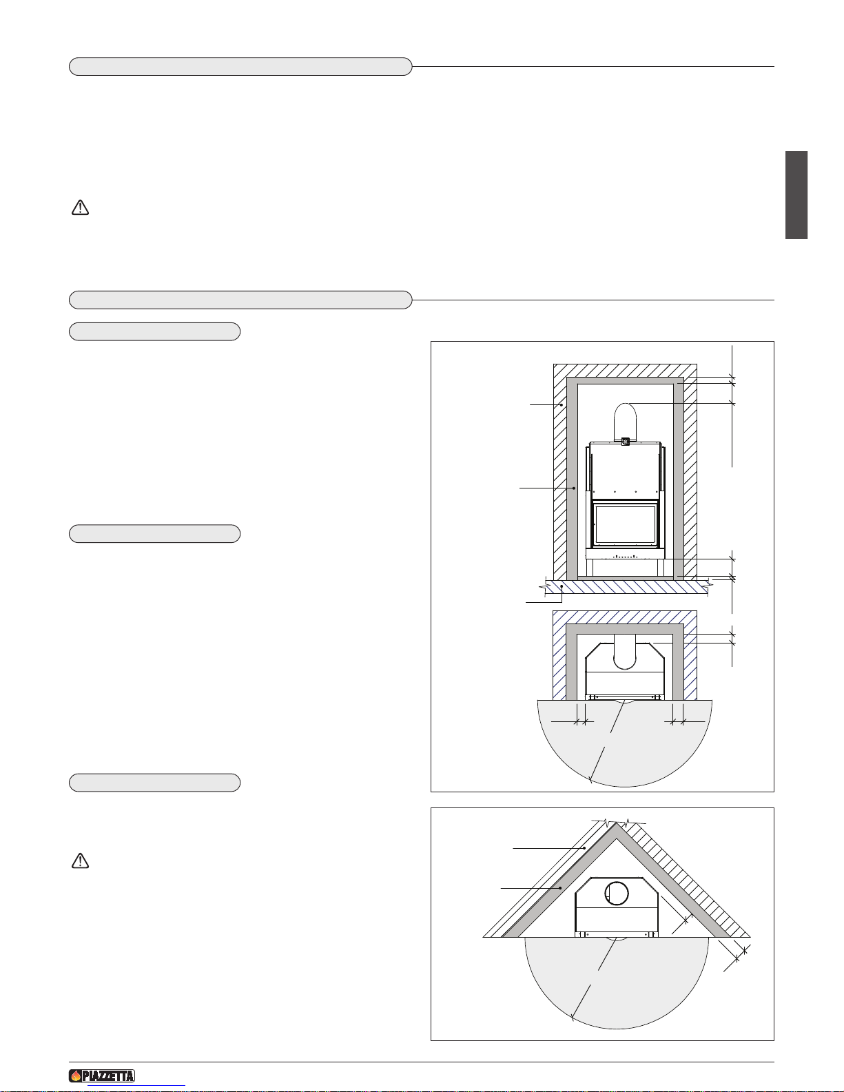
1.9 MINIMUM SAFETY DISTANCES
- FLAMMABLE WALLS: the stove may be installed near flammable
walls provided suitable protection consisting of insulating and noncombustible material is inserted.
To insulate the stove and to install the surround correctly, construct
a lining wall in non-flammable material (e.g. plasterboard) and insert a “C” thick layer of insulating material between the two walls.
Always leave a gap “A” between the stove and the lining wall. (Fig.
15 - 16)
- NON-FLAMMABLE WALLS: always leave a gap of 5 cm between
the stove and the lining wall.
- FLAMMABLE CEILING: create an 8 cm false ceiling of non-flam-
mable material.
The minimum distance between the false ceiling and connection to
the flueway must be 20 cm, while the flue connection must be insulated with at least 3 cm thick non-flammable material that is resistant to high temperatures. (Fig. 15-16)
If the surround canopy and the flue connection are metal, the minimum distance from the false ceiling may be reduced to 10 cm,
but the insulation of the connection to the flueway must be at least
6 cm thick.
- NON-FLAMMABLE CEILING: the minimum distance between the
ceiling and connection to the flueway must be 20 cm.
If the floor is made of flammable material, it must be protected with
a layer of insulating material of thickness “E” while an air space “D”
must be left between the fireplace and the floor. (Fig. 15)
For insulation, use insulating material with the characteristics given in the paragraph “SUITABLE HEAT INSULATING
MATERIALS”.
H07023830 / DT2000612 - Rev. 01
39
English
A C
B E D
Flammable
wall
Insulating
material
Flammable
floor
R
8 cm20 cm min.
Fig. 15
DT2032811-00
A
C
R
Flammable
wall
Insulating
material
Fig. 16
DT2032812-00
WALLS
CEILING
FLOOR
Page 10
There is a radiation area in front of the stove which must be kept free of any flammable element, such as: carpets, curtains, wood furnishings,
ornaments, flammable liquids, fire-lighting products or firewood, etc.
T
his area is defined by the distance “R”. (Fig. 15 - 16)
Failure to comply with the above could cause a fire!!!
The minimum safety distances to be observed are given in the table below:
H07023830 / DT2000612 - Rev. 01
40
English
MODELS
IL 65/49 – 65/54 – 75/58 – 75/64
A clearance from stove to flammable wall at the side cm 4
B clearance from stove to flammable wall at the rear cm 4
C thickness of insulating material for wall to side/rear cm 6
D clearance from stove to flammable floor cm 4
E thickness of floor insulating material cm 4
R minimum clearance from stove front to flammable material cm 100
D
T2011907-00
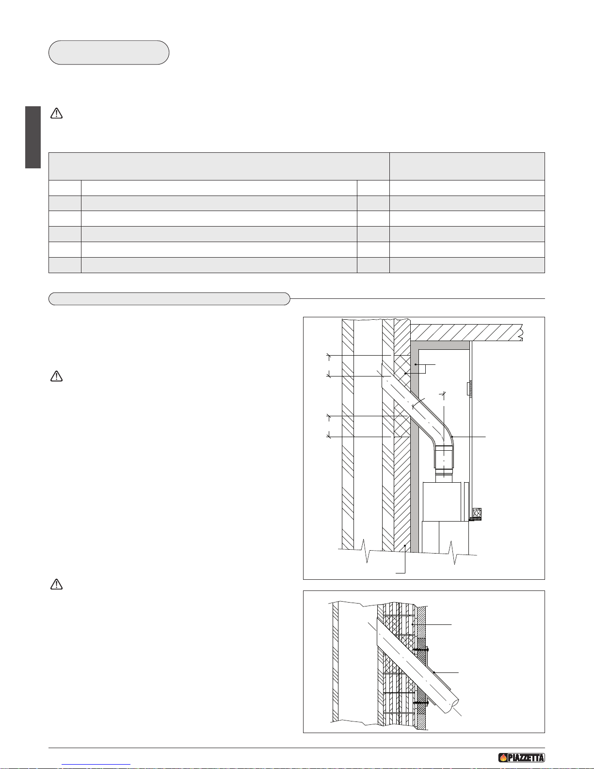
1.10 CONNECTION TO THE FLUEWAY
Connection to the flueway must be done using pipes as short as
possible without narrowing or restrictions and with a maximum slope
of 45°.
Flexible metal or asbestos-cement pipes must not be used
Pipes and bends or elbows must be made in compliance with current
regulations
WARNINGS WITH REGARD TO FLAMMABLE WALLS OR CEILING:
If the connection has to go through elements or walls in heatsensitive flammable materials, create a layer of at least 20 cm
insulation around the pipe. (Fig. 17)
After having drilled a hole in the wall to insert the pipe through into
the flueway, the air gaps must be filled with non-flammable, resilient
materials with a reduced capacity of heat transmission (e.g.
lightweight concrete). (Fig. 18)
Check that the connection to the flueway is gas/smoke-tight, since
the appliance operates in a vacuum.
It is recommended that the connector pipes be insulated with
insulating material having the characteristics given in the
paragraph “SUITABLE HEAT INSULATING MATERIALS”.
Check that the pipe does not penetrate too far into the flueway,
thereby choking the pipe for the passage of smoke and combustion
gases.
45°
FLUE
20
20
Insulation
Wall to be protected
Insulation
Maximum
Fig. 17
DT2030269-01
FLUE
Air gaps
Wall connection
flange
Fig. 18
DT2030270-00
D
T2012032-00
DANGER AREA
FOR RADIATION
Page 11
English
H07023830 / DT2000612 - Rev. 01
41
English
DT2011913-00
1.11 LINING WALL
The surround or the lining wall of the fireplace must be self-supporting regardless of the materials with which it is made and under no
circumstances must it come into contact with the fireplace. Furthermore, the surround must be made with non-flammable materials in
c
ompliance with regulations.
For Gruppo Piazzetta S.p.A. surrounds, follow the instructions enclosed with the product.
Testing and lighting for first time
Only a visual inspection can be made in the intermediate stage for fireplaces, stoves and appliances that must be assembled or clad with
b
rickwork or require the use of cement binders. In this case operation of the whole installation must be tested after all the building works
directly connected with the “LIGHTING FOR THE FIRST TIME” test have been completed, following the instructions given in the booklet.
D
T2010177-00
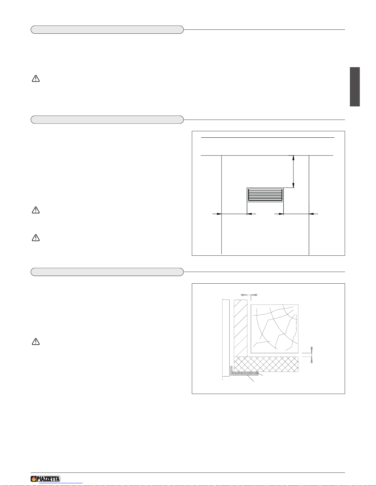
1.12 HOOD GRILLE
The hood grille has the function of allowing air to pass from inside
the hood to the environment or vice versa if the Multifuoco system
is installed.
Warm air comes out of the hood grille with the natural convection
system and it is therefore necessary to maintain the safety distances
from flammable materials such as: flammable ceilings or walls,
ledges/beams, furniture, curtains, etc.. The hood grille must be
installed at least 50 cm from the ceiling and with at least 30 cm safety
distance to the sides.
For the hood grille size, see the “TECHNICAL DATA” paragraph.
A non-closable hood grille must be installed without
connecting it to the stove so that the warm air that has
stratified inside the lining wall can flow out.
With a ceiling over 3 metres high, a NON-CLOSABLE hood
grille must be installed on the hood lining at a height of 30 cm
from the ceiling to allow the stratified air to flow out.
MIN. 30 CM MIN. 30 CM
MIN. 30 CM
FLAMMABLE MATERIALS
FLAMMABLE MATERIALS
CEILING IN FLAMMABLE MATERIAL
Fig. 19
D
T2030271-00
DT2010178-00
1.13 WOOD MANTEL PROTECTION
Wooden finishes, e.g. Wood mantels, may be mounted on the
surround.
Wood mantels must be:
- installed outside the heat radiation area;
- self-supporting;
- installed with 1cm air gap from the surround or from the heating
part;
The expansion joint is in ceramic fibre, which has the
function of insulating the surround from the metal structure of
the stove.
1 cm
Fireplace
Hood or surround
1 cm
Surround
Expansion joint
Load-bearing axis
Wood
mantel
Fig. 20
DT2030272-00
Page 12

English
42
H07023830 / DT2000612 - Rev. 01
DT2010027-02
1.14 PREVENTION OF DOMESTIC FIRES
The product must be installed and used in compliance with the manufacturer’s instructions and European and national standards as well as
local regulations.
When a flue pipe passes through a wall or a ceiling, special installation methods must be applied (protection, thermal insulation,
distances from heat-sensitive materials, etc.) See the paragraph “CONNECTION TO THE FLUEWAY”
- It is also recommended that all elements made of combustible or inflammable material, such as beams, wooden furniture, curtaining,
f
lammable liquids, etc. be kept outside the heat radiation range of the stove and at a distance of at least 1 m from the heating block.
- For other information, see the paragraph “MINUMUM SAFETY DISTANCES” and “CONNECTION TO THE FLUEWAY”.
- The flue pipe, chimney stack, chimney and fresh air intake must always be free of obstructions, clean and checked periodically, that is, at
least twice during the seasonal period from the lighting of the stove and during its use. When the stove has not been used for some time
it is advisable to carry out the checks mentioned above. For further information, consult a chimneysweep.
- Only use recommended fuels (See paragraph “FUEL”).
Page 13
English
43
H07023830 / DT2000612 - Rev. 01
2.0 TECHNICAL DATA AND SPECIFICATIONS
DT2012033-00
DT2012034-00
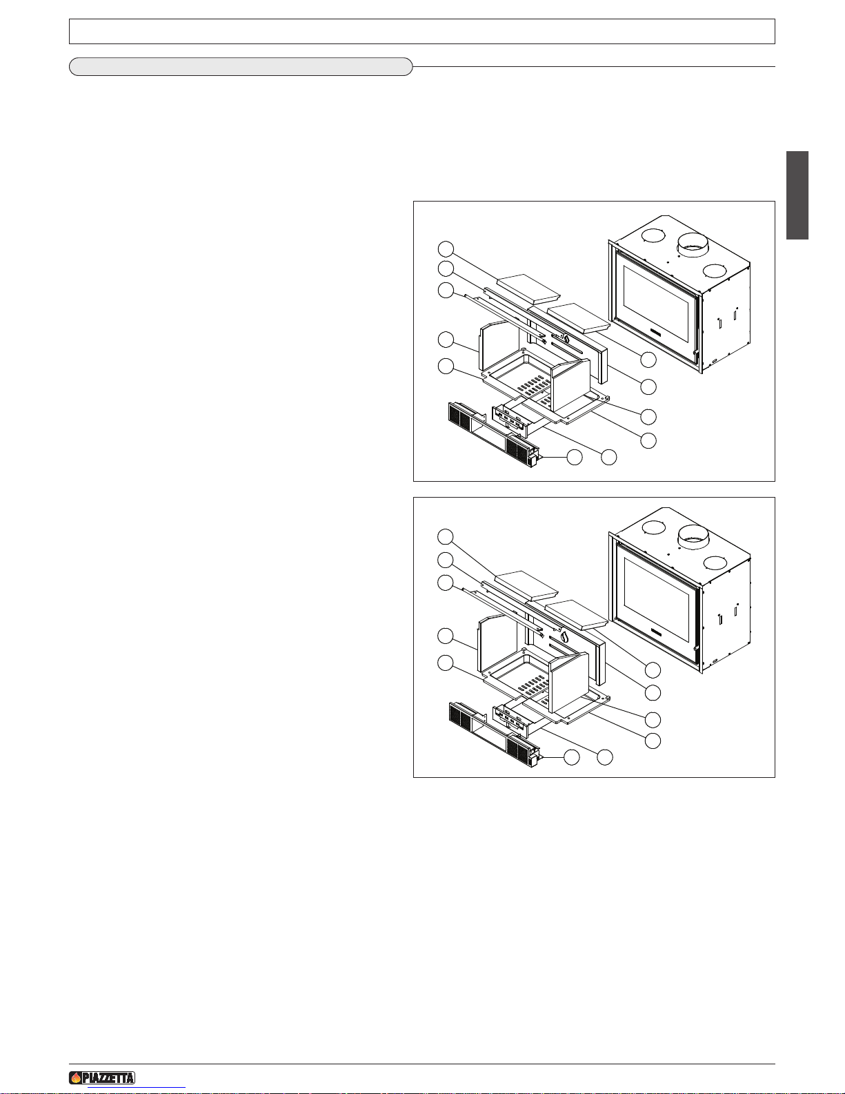
2.1 DESCRIPTION OF THE APPLIANCE
The new line of wood-burning fireplace inserts IL comprises a range of compact stoves designed specifically for insertion into and therefore
the recovery of traditional fireplaces where it is necessary to improve performance and safety of use. The fireplace insert consists of an
i
nternal high gauge steel body (thickness 4 mm) and an outer steel jacket. The structure is designed to ensure heating efficiency and
considerable heat recovery by the heat exchange that takes place between the walls of the hearth and the gap between the stove body and
its jacket, which allows air to circulate and be heated without it coming into contact with the flame. A ventilation kit is installed that, when
switched on, increases the heating action of the air by forcing it to circulate quicker and pushing it further away from the source of heat.
1
2
3
4
5
5
6
7
8
9
10
IL 65/49
D
T2032852-00
N
o Description . . . . . . . . . . . . . . . . . . . . . . . . . .Qty
1) L.H. grate in cast iron . . . . . . . . . . . . . . . . . . . . . . . . .1
2) Aluker left side panel 267x262 . . . . . . . . . . . . . . . . . .1
3) Flue gas/smoke damper . . . . . . . . . . . . . . . . . . . . . . .1
4) Baffle plate support . . . . . . . . . . . . . . . . . . . . . . . . . .1
5) Aluker baffle plate 268x202 . . . . . . . . . . . . . . . . . . . .2
6) Aluker back panel 545x205 . . . . . . . . . . . . . . . . . . . .1
7) Aluker right side panel 267x262 . . . . . . . . . . . . . . . . .1
8) R.H. grate in cast iron . . . . . . . . . . . . . . . . . . . . . . . .1
9) Ash drawer . . . . . . . . . . . . . . . . . . . . . . . . . . . . . . . . .1
10) Fan box . . . . . . . . . . . . . . . . . . . . . . . . . . . . . . . . . . .1
1
2
3
4
5
5
6
7
8
910
IL 65/54
DT2032860-00
No Description . . . . . . . . . . . . . . . . . . . . . . . . . .Qty
1) L.H. grate in cast iron . . . . . . . . . . . . . . . . . . . . . . . . .1
2) Aluker left side panel 267x312 . . . . . . . . . . . . . . . . .1
3) Flue gas/smoke damper . . . . . . . . . . . . . . . . . . . . . . .1
4) Baffle plate support . . . . . . . . . . . . . . . . . . . . . . . . . .1
5) Aluker baffle plate 268x202 . . . . . . . . . . . . . . . . . . . .2
6) Aluker back panel 545x255 . . . . . . . . . . . . . . . . . . . .1
7) Aluker right side panel 267x312 . . . . . . . . . . . . . . . .1
8) R.H. grate in cast iron . . . . . . . . . . . . . . . . . . . . . . . .1
9) Ash drawer . . . . . . . . . . . . . . . . . . . . . . . . . . . . . . . . .1
10) Fan box . . . . . . . . . . . . . . . . . . . . . . . . . . . . . . . . . . .1
Page 14
Italiano
44
H07023830 / DT2000612 - Rev. 01
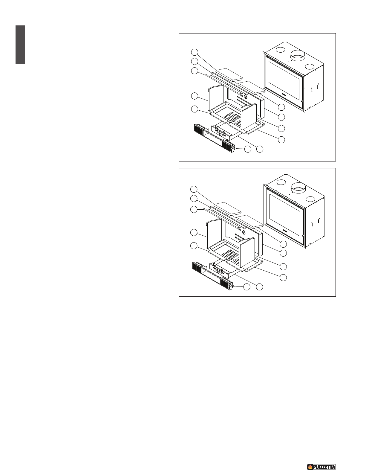
1
2
3
4
5
5
6
8
910
7
IL 75/58
D
T2032861-00
No Description . . . . . . . . . . . . . . . . . . . . . . . . . .Qty
1) L.H. grate in cast iron . . . . . . . . . . . . . . . . . . . . . . . . .1
2) Aluker left side panel 267x352 . . . . . . . . . . . . . . . . .1
3
) Flue gas/smoke damper . . . . . . . . . . . . . . . . . . . . . . .1
4) Baffle plate support . . . . . . . . . . . . . . . . . . . . . . . . . .1
5) Aluker baffle plate 318x202 . . . . . . . . . . . . . . . . . . . .2
6) Aluker back panel 645x295 . . . . . . . . . . . . . . . . . . . .1
7) Aluker right side panel 267x352 . . . . . . . . . . . . . . . .1
8
) R.H. grate in cast iron . . . . . . . . . . . . . . . . . . . . . . . .1
9) Ash drawer . . . . . . . . . . . . . . . . . . . . . . . . . . . . . . . . .1
10) Fan box . . . . . . . . . . . . . . . . . . . . . . . . . . . . . . . . . . .1
1
2
3
4
5
5
6
7
8
910
IL 75/64
DT2032862-00
No Description . . . . . . . . . . . . . . . . . . . . . . . . . .Qty
1) L.H. grate in cast iron . . . . . . . . . . . . . . . . . . . . . . . . .1
2) Aluker left side panel 267x412 . . . . . . . . . . . . . . . . .1
3) Flue gas/smoke damper . . . . . . . . . . . . . . . . . . . . . . .1
4) Baffle plate support . . . . . . . . . . . . . . . . . . . . . . . . . .1
5) Aluker baffle plate 318x202 . . . . . . . . . . . . . . . . . . . .2
6) Aluker back panel 645x355 . . . . . . . . . . . . . . . . . . . .1
7) Aluker right side panel 267x412 . . . . . . . . . . . . . . . .1
8) R.H. grate in cast iron . . . . . . . . . . . . . . . . . . . . . . . .1
9) Ash drawer . . . . . . . . . . . . . . . . . . . . . . . . . . . . . . . . .1
10) Fan box . . . . . . . . . . . . . . . . . . . . . . . . . . . . . . . . . . .1
Page 15
Italiano
45
H07023830 / DT2000612 - Rev. 01
DT2012035-00
2.2 ACCESSORIES AND EQUIPMENT
D
T2012036-00
2.3 FEATURES
Fuel . . . . . . . . . . . . . . . . . . . . . . . . . . . . . . . . . . . . . . . . . . . . . . . . . wood (see “FUEL” paragraph)
Fireplace insert . . . . . . . . . . . . . . . . . . . . . . . . . . . . . . . . . . . . . . . . black painted steel
Hearth . . . . . . . . . . . . . . . . . . . . . . . . . . . . . . . . . . . . . . . . . . . . . . . Aluker
Grate . . . . . . . . . . . . . . . . . . . . . . . . . . . . . . . . . . . . . . . . . . . . . . . . cast iron
Door . . . . . . . . . . . . . . . . . . . . . . . . . . . . . . . . . . . . . . . . . . . . . . . . with ceramic glass heat-resistant up to 750°C
Handle: . . . . . . . . . . . . . . . . . . . . . . . . . . . . . . . . . . . . . . . . . . . . . . in steel, concealed flush with front
Primary air control . . . . . . . . . . . . . . . . . . . . . . . . . . . . . . . . . . . . . manual regulation
Secondary air control . . . . . . . . . . . . . . . . . . . . . . . . . . . . . . . . . . . manual regulation
Tertiary air control . . . . . . . . . . . . . . . . . . . . . . . . . . . . . . . . . . . . . . calibrated
Flue gas/smoke damper . . . . . . . . . . . . . . . . . . . . . . . . . . . . . . . . . automatic opening
Ash tray. . . . . . . . . . . . . . . . . . . . . . . . . . . . . . . . . . . . . . . . . . . . . . removable
Flue gas outlet. . . . . . . . . . . . . . . . . . . . . . . . . . . . . . . . . . . . . . . . . top
Heating . . . . . . . . . . . . . . . . . . . . . . . . . . . . . . . . . . . . . . . . . . . . . . natural convection or forced ventilation with two front hot air outlets
D
escription
A
ccessories
Right-hand glove In kit
Silicone paint spray can In kit
Hexagonal door handle tool In kit
Pipes and elbows for connection to the flueway Optional
Flue collar Optional
Front surround trim kit Optional
Mantel insulation kit Optional
Hot air pipe connector Ø 120 mm Optional
DT2011766-00
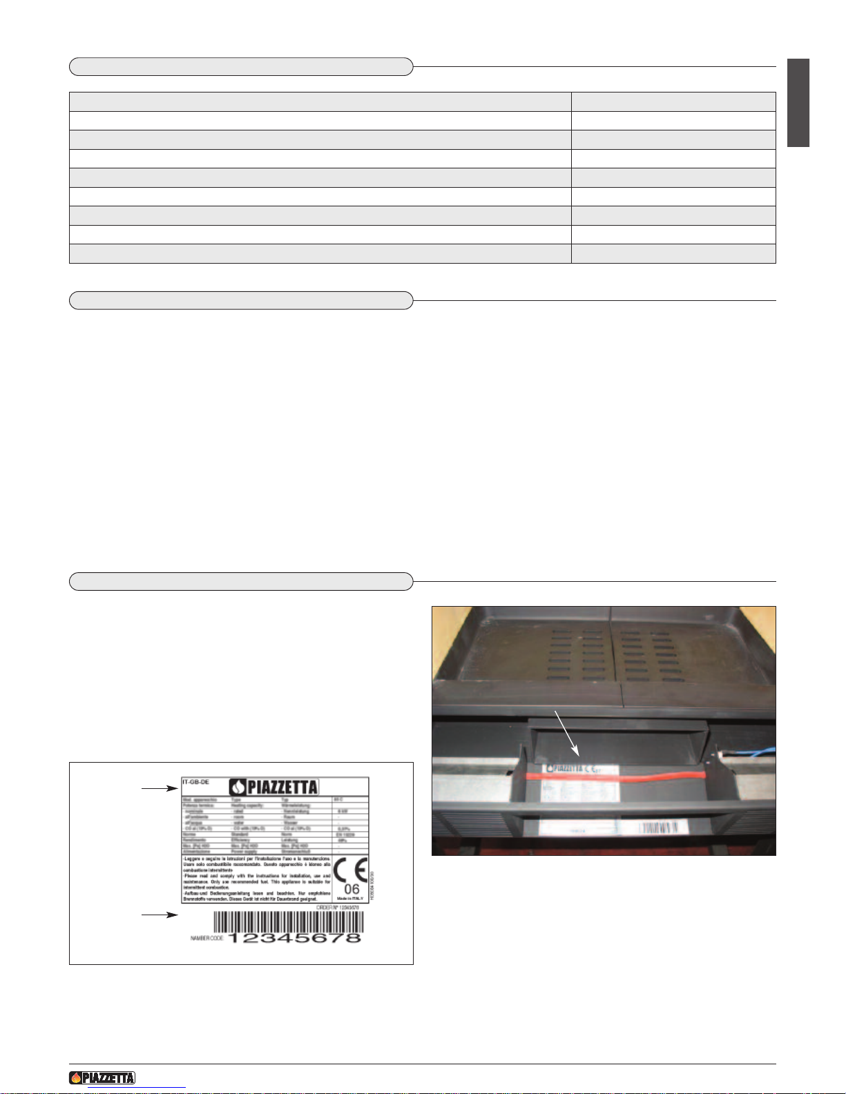
2.4 PRODUCT IDENTIFICATION DATA
Fig. 22
DT2032904-00
Fig. 21
DT2030944-00
Every product is identified by a rating plate showing the model and
the performance of the appliance as well as a plate giving the serial
number.
Both plates are located as indicated in the picture.
A label bearing the serial number is also applied on the cover last
page of the “INSTALLATION, OPERATION AND MAINTENANCE”
booklet.
Always give the information shown on these plates to the dealer or
the Service Centre when requesting service or spare parts.
Product name
Serial number
PRODUCTION
IDENTIFICATION
AND RATING PLATE
Page 16
H07023830 / DT2000612 - Rev. 01
46
English
DT2012031-00
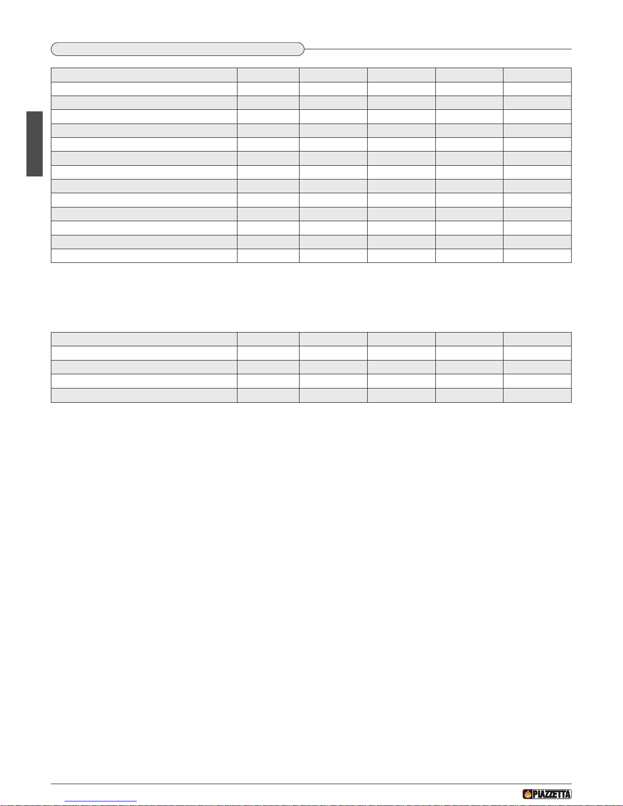
2.5 TECHNICAL DATA
These data are obtained using beech wood with moisture content below 20% and with intervals between stoking-up of approximately one
hour.
Use of this appliance is intermittent.
Technical data with closed grate for flue calculations
The above values correspond approximately to a flue with section Ø 25 cm up to 4.5 m in height and Ø 18 over 4.5 m.
For model IL 65/49 and IL 65/54: Ø 20 cm up to 4.5 m in height and Ø 15 over 4.5 m.
U.M. IL 65/49 IL 65/54 IL 75/58 IL 75/64
Rated heat output kw 7.0 7.0 9.0 9.0
Consumption at rated heat output kg/h 1.9 1.9 2.4 2.4
Thermal efficiency % 80.1 80.1 80 80
CO content (with 13% O2) % 0.09 0.09 0.08 0.08
Certified in according to norm - EN 13229 EN 13229 EN 13229 EN 13229
H
omologation number
- R
RF-29 10 2308RRF-29 10 2308RRF - 29 10 2275RRF - 29 10 2275
Flue diameter cm 15 15 18 18
Firebox opening (WxH) cm 49x24.5 49x29.5 59x33.5 59x39.5
Firebed cm
2
1346 1346 1618 1618
W
eight
k
g
1
05
1
10
1
25
1
32
Fresh air intake (recommended minimum section) cm
2
100 100 100 100
Combustion air fl ow rate with open intake m3/h - - - Convective air inlet/outlet (recommended minimum section)
cm
2
350/350 350/350 350/350 350/350
U.M. IL 65/49 IL 65/54 IL 75/58 IL 75/64
Rated heat output kw 7.0 7.0 9.0 9.0
Mass of smoke g/s 5.4 5.4 8.0 8.0
Average temp. smoke in gas discharge pipe °C 345 345 335 335
Minimum draught Pa 12 12 12 12
Page 17
H07023830 / DT2000612 - Rev. 01
47
English
2
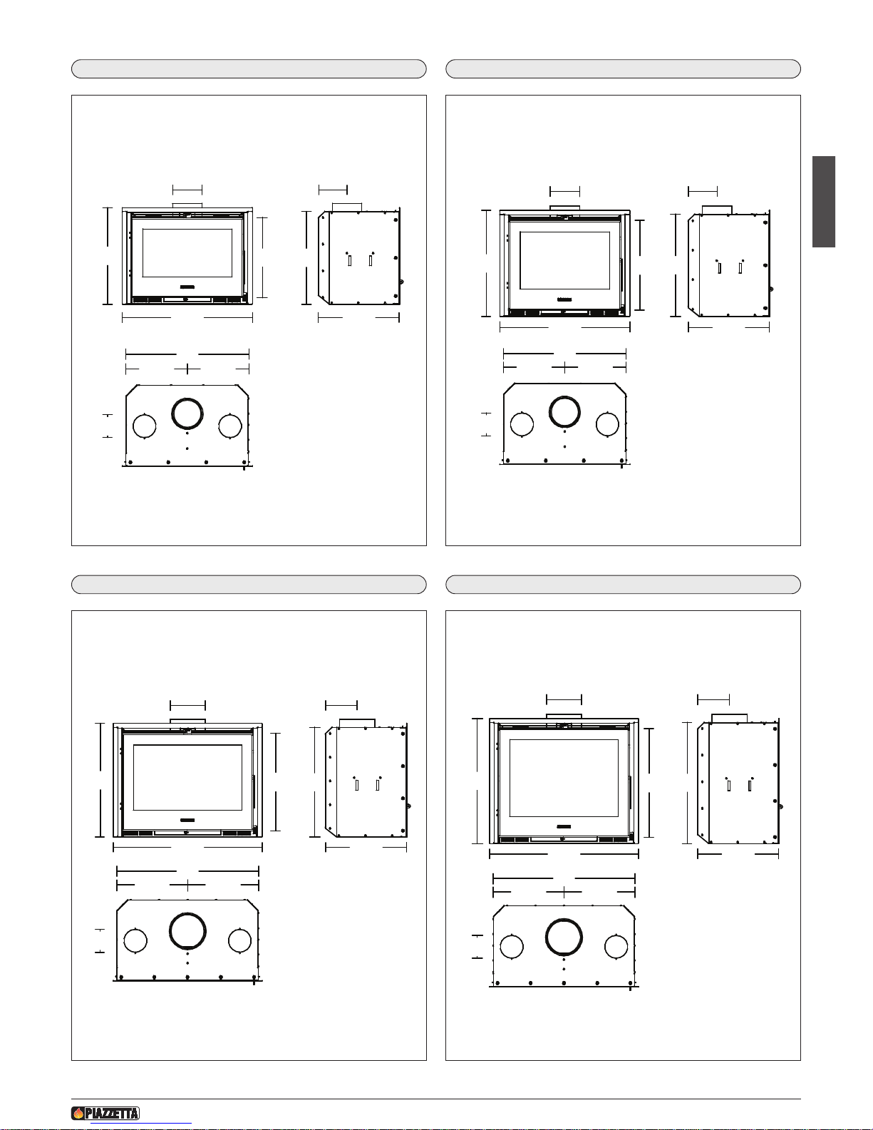
.6 DIMENSIONS IL 65/49
Ø15
42
15
51
68,5
65
32,5 32,5
42,5
49
12Ø
DT1020417-00
2.8 DIMENSIONS IL 75/58
Ø18
51
16,5
60
78,5 42,5
37,5 37,5
75
12Ø
58
DT1020419-00
2
.7 DIMENSIONS IL 65/54
Ø15 15
47
68,5
56
42,5
32,5 32,5
65
12Ø
54
DT1020418-00
2.9 DIMENSIONS IL 75/64
Ø18 16,5
57
78,5 42,5
66
64
37,5 37,5
75
12Ø
DT1020420-00
Dimensions in cm
Dimensions in cm
Dimensions in cm
Dimensions in cm
Page 18
H07023830 / DT2000612 - Rev. 01
48
English
3.0 INSTALLATION
DT2012037-00
Profili di compensazione
Dadi M4
Fig. 23
D
T2032863-00
DT2012037-00
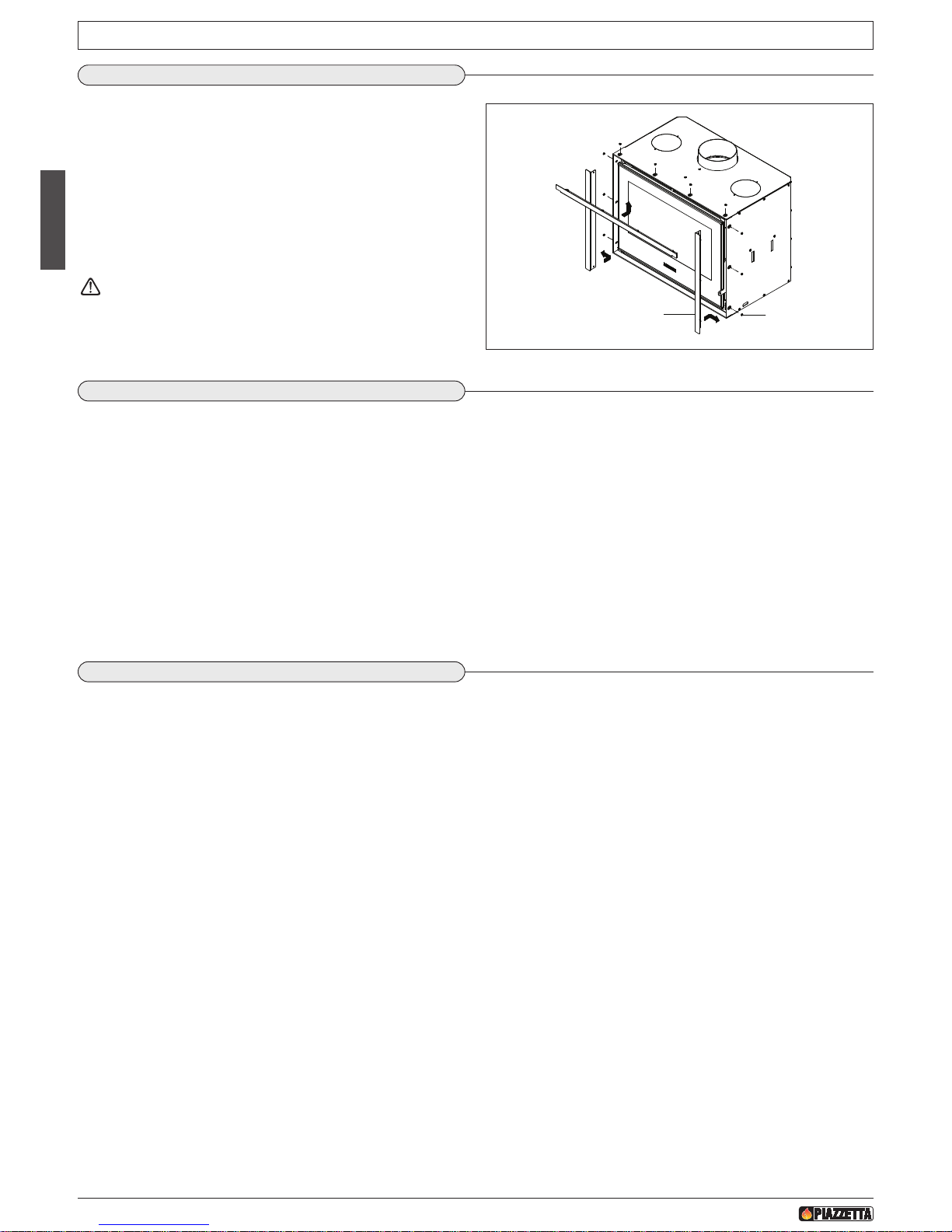
3.1 PREPARING FIREPLACE INSERTS
The wood-burning fireplace insert “IL” is provided with upper and
side filler elements.
B
efore placing the insert in its final location, the filler elements must
be screwed to it using the M4 nuts provided in the kit, first fitting the
side elements and then the upper one (fig. 23).
Push the filler elements as far as they will go to the rear before fully
tightening the nuts; if necessary it is in any case possible to make
s
mall adjustments and alignments by making the pins of the ele-
ments slide in the relative slots.
Even if the “FRONT SURROUND TRIM KIT” is to be used, the
filler elements must be installed.
D
T2012037-00
3.2 BEFORE INSTALLING THE INSERT
• Check the flue pipe, remove any closures or dampers and clean the pipe.
• Check that the structure of the existing fireplace/hearth is in good condition and if it is not, it must be made good.
• Check that there is a fresh air intake and if there is not, make a hole with a minimum section of 150-200 cm².
• Make sure there is a 220V electric socket available and that the fan power cable can pass.
• Rigid metal pipes must be used for connection to the flueway and must be installed so that no gas can enter into or leak out of the system.
• The flueway must always have an equal or greater section than that of the flue gas outlet pipe indicated in the paragraph “TECHNICAL DATA”.
• If building work is required to change the existing fireplace, before completing the masonry try fitting the fireplace insert.
• If the fireplace insert is installed in a larger hearth venting to an existing flueway, PIAZZETTA S.p.A. will supply, on request, an optional sur-
round trim. Follow the attached instructions before installing the insert.
• To install the flue collar, carefully read the accompanying instructions.
D
T2012037-00
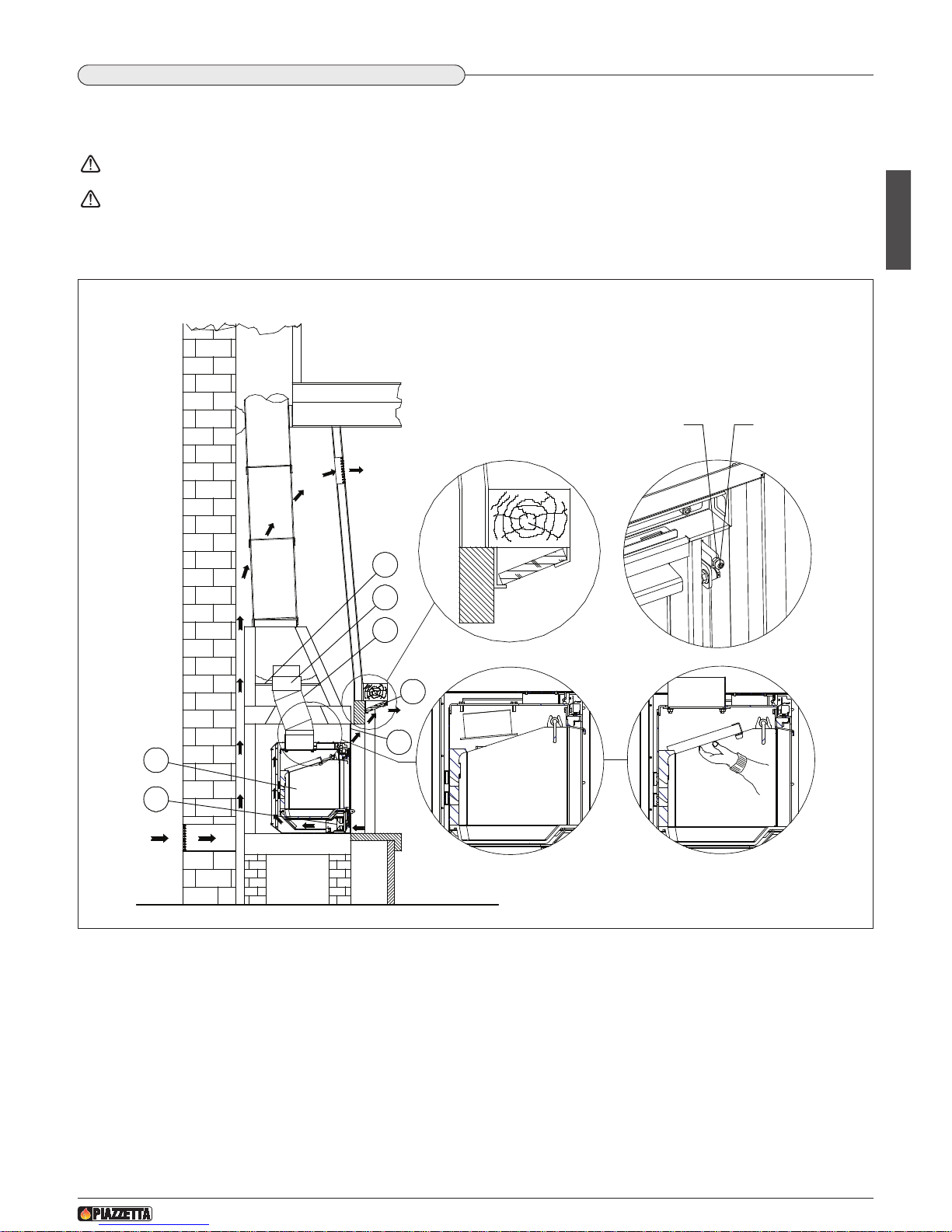
3.3 INSTALLATION
• Place and wall-in the flue collar (optional) for the flue gas outlet pipe to pass through, as low down as possible in the canopy (see atta-
ched instructions).
• Use fire-retardant materials between the flueway and the flue collar to create a hermetic insulating layer.
• Insert the connector and support it with the relative pipe clip.
• Fit the fireplace insert into the existing fireplace, placing the flue gas outlet collar in line with the hole of the flue collar.
• Working through the flue gas hole, remove the flue gas outlet pipe support and lower the pipe towards the fireplace insert. Insert the flue
gas outlet collar. Fit the flue collar with the pipe into position from inside the insert, and fasten it to the ceiling of the fireplace insert using
the four nuts and washers provided in the kit (see detail “A” fig. 24).
• Insert the flue gas/smoke baffle plates with relative support in the upper part (see detail ”B” fig. 24).
• Check that everything is fitted correctly and light the fire so that it burns slowly.
Filler elements Nuts M4
Page 19
H07023830 / DT2000612 - Rev. 01
49
English
3
1
2
5
6
4
7
A
B
D
C
Dado M5 Vite
F
ig. 24
DT2012037-00
3.4 ADJUSTING THE FLUE GAS/SMOKE DAMPER
To adjust the flue gas/smoke damper, loosen the nut M5, tighten the screw to the required position and then tighten the nut M5 again (see
detail “D” fig. 24).
For nominal power set the smoke damper so that, with the door closed, it is also fully closed.
Whether the fireplace insert is installed in an existing fireplace or in a new fireplace with a wooden mantel, the underside of the
mantel must be insulated.
F
or this purpose there is a mantel insulating kit (optional), which may be fixed onto all wooden mantels (see detail “C” fig. 24
and instructions regarding the mantel insulation kit).
DT2032903-00
1 Flue collar
2 Connector
3 Backfill
4 Mantel insulation
5 Front surround trim
6 Fireplace insert
7 Internal ventilation kit
Nut M5 Screw
Page 20
English
50
H07023830 / DT2000612 - Rev. 01
4.0 VENTILATION
DT2012038-00
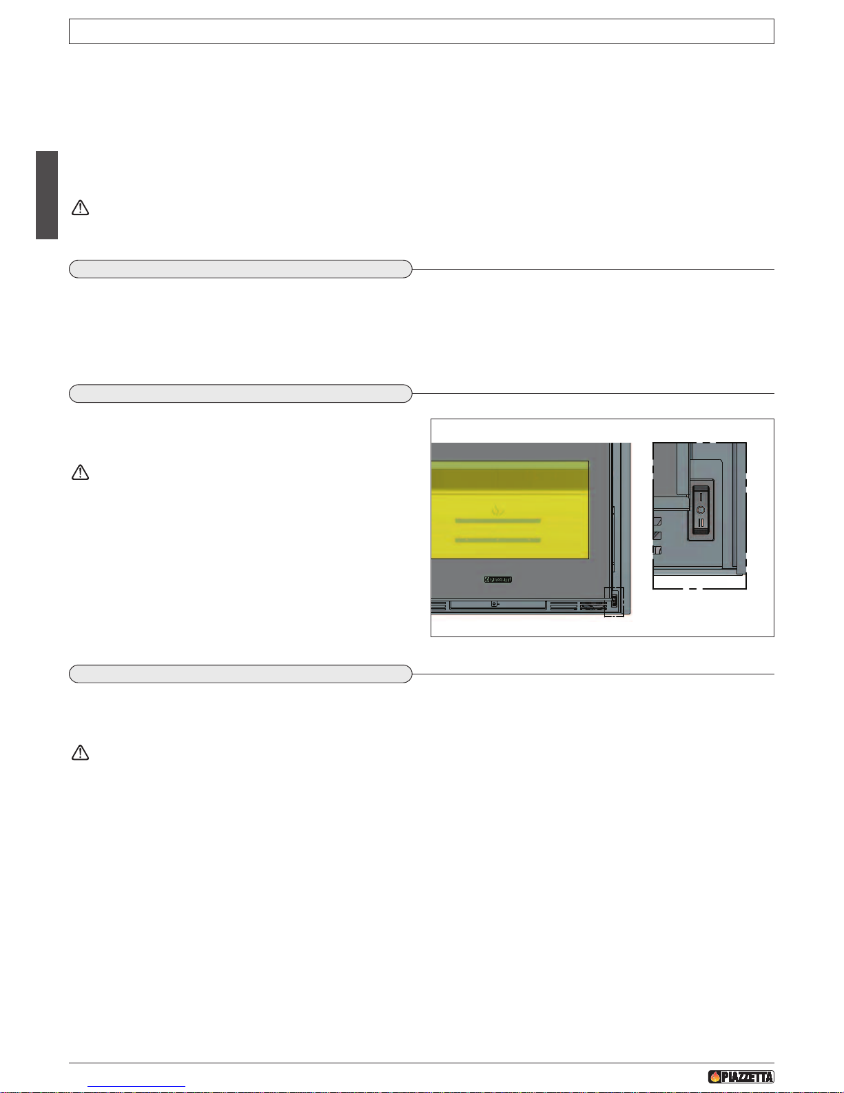
The wood burning fireplace inserts IL are fitted with a ventilation system consisting of two fans with connection terminals, a thermostatic
sensor and a selector switch with three settings: “I – 0 – II”.
The ventilation system should be considered as: in the manual mode of operation (first speed) when in position “I”, automatic mode of
o
peration (first speed) when in position “0”, automatic mode of operation (second speed) when in position “II”. In the automatic mode of
operation positions (0 and II), the fan motors are controlled by the thermostatic sensor, which therefore acts as a switch; under normal
operating conditions, when the temperature inside the fireplace insert is more than around 60°C, the sensor closes the electrical circuit
thereby automatically activating the ventilation system and vice versa if the temperature is lower.
A
suitable system for cutting off the electricity supply (plug or line circuit breaker) must be installed upstream of the wiring provided.
D
T2012038-00
4.1 FAN SPECIFICATIONS
Free flow rate . . . . . . . . . . . . . . 2 x 50 [m³/h]
Power . . . . . . . . . . . . . . . . . . . . 2 x 12 [W]
Frequency . . . . . . . . . . . . . . . . 50 [Hz]
Voltage . . . . . . . . . . . . . . . . . . 230 [V]
Fig. 25
DT2032867-00
D
T2012038-00
4.2 USE OF THE FANS
The fan motors can be activated immediately by moving the selector
switch (to be found bottom right of the product) to position “I”.
In the manual mode position, the fans continue to work even
after the hearth has completely cooled.
When the fire is burning steadily (approx. 30 minutes after lighting),
you can put the selector switch to position “I”. After approx. 2-3
hours you can put the switch to position “0 or II”, so that the fans are
switched on and off by the thermostatic sensor, which acts on the
fans when the temperature is around 60° C. (Fig. 25).
DT2012038-00
4.3 FAN MAINTENANCE
Periodically and at least once a year, clean the fans, removing the dust that can build up on the rotating blades.
Follow the procedure given in the section “REMOVING THE FAN BOX” for cleaning and removing the fans.
All work on the appliance and on the wiring must be carried out by qualified personnel and with the electricity supply switched off.
Page 21
English
51
H07023830 / DT2000612 - Rev. 01
Fig. 26
D
T2032870-00
DT2012038-00
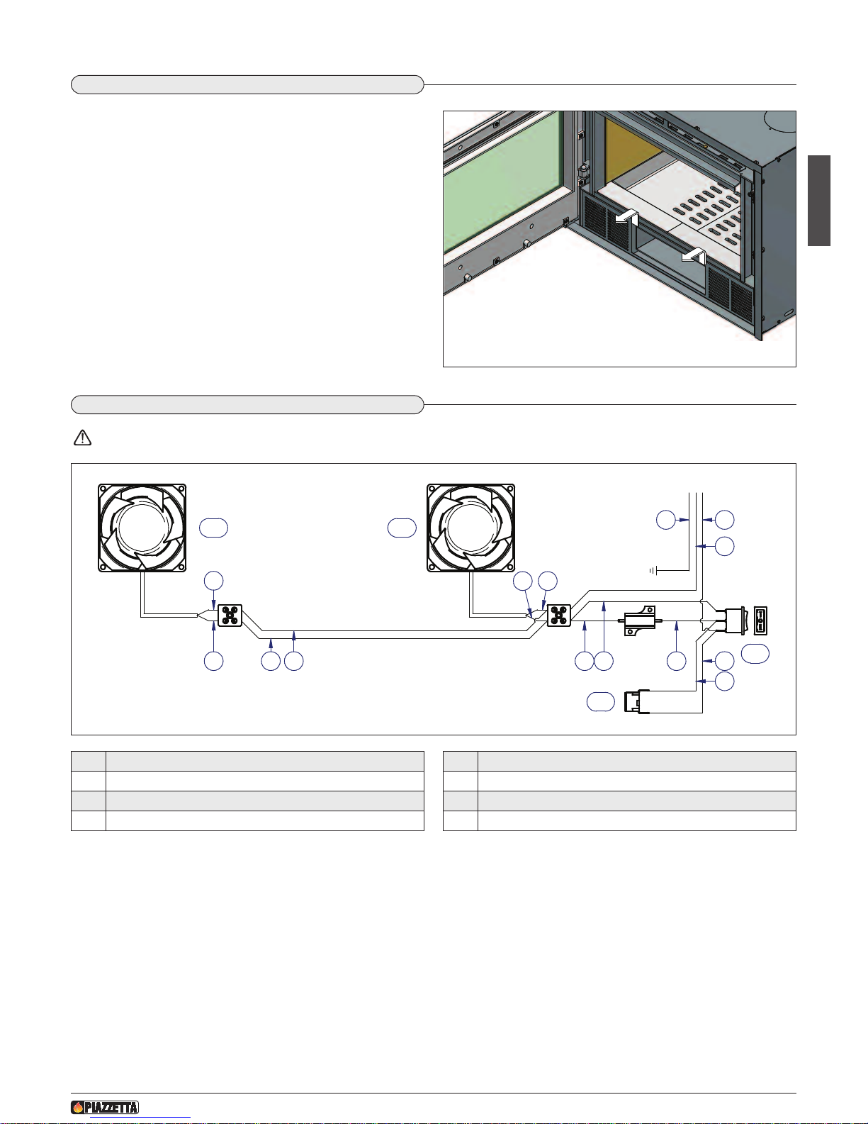
4.4 REMOVING THE FAN BOX
• Make sure that the power supply to the motors is cut off.
•
Open the door and remove the ash drawer. Now pull out the fan box
by grasping it towards the sides of the opening that has been left
free by the removal of the ash drawer and gently moving it upwards and outwards. Take care not to disconnect or break the
power leads or the thermostatic sensor wires. (Fig. 26).
•
Carry out maintenance or cleaning.
To refit the fan box, proceed in the reverse order to above.
1 2
223
3
3
3
3
33 3
3
A
B
C C
3
DT2032845-00
D
T2012038-00
4.5 FAN WIRING DIAGRAM
ALL WORK MUST BE CARRIED OUT BY QUALIFIED PERSONNEL AND WITH THE POWER CUT OFF.
Pos. Key to parts
A Selector switch
B Thermostatic sensor
C Fan
No. Key to colours
1 Yellow-green
2 Brown
3 Blue
Fig. 27
Page 22
English
52
H07023830 / DT2000612 - Rev. 01
* Approximate values.
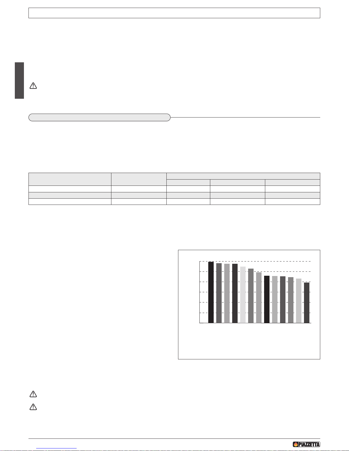
It is a good rule to purchase timber during the summer (June-July), since woods are cut down mostly in the autumn and you can therefore
be sure that the timber has already been seasoned for approximately 1 year.
Firewood can be classified in two qualities: “good” and “mediocre or poor".
This classification is according to the heat yield of the wood, the longest flame time it provides, its composition and density.
Good fuels
- Recommended timber comes from the family of broadleaf hard-
woods: beech, hornbeam, oak, false acacia, ash, birch, maple,
elm.
- All low-resin and close-grained woods (that is hard and heavy tim-
ber) are most suitable, since they provide the stove with a steady,
continuous flame.
Mediocre or poor fuels
- Timber that is not recommended comes from the family of conifers,
willow, poplar and alder. These light soft woods are resinous and
therefore create more soot, few embers and incandescent sparks,
while requiring more frequent cleaning of the flue and the fireplace.
- Another characteristic of softwood is that it gives a lively but short-
lived flame and the consumption is higher for the same heat output.
Unsuitable fuels
- Never use wet wood, tarred wood or pellets.
- It is also best not to use: refuse (rubbish), waste paper; paper briquettes; plywood or chipboard; fibreboard; packaging materials; painted
wood or wood coated with synthetic material, plastic laminates, cardboard or milk cartons.
Under no circumstances use liquid fuel of any kind whatsoever.
All these materials or similar ones could be hazardous for the user, damage the fireplace, the flue connection and the flue, and,
last but not least, pollute the environment.
5.0 USE
DT2012039-00
D
T2010043-01
5.1 FUEL
Use well-seasoned and dry wood with less than 20% moisture content.
Wood that is ready to burn must have been dried in the open air sheltered from rain or snow for at least 2 years after having been cut.
The lower the moisture content of the wood the higher its heating power. Freshly cut wood has 50% less heat value than dry wood.
Burning wood that is too wet means wasting most of the calories for evaporation of the water contained in it and, in particular, the walls of
the combustion chamber and the flue become fouled and encrusted thereby affecting efficiency.
The table below shows how the heating power decreases as the moisture content increases.
• Certain basic facts can be all-important for best performance and getting the most out of your appliance. Please find below some basic in-
formation intended to be of use with regard to the choice of firewood, the adjustment of the dampers and proper operation of the appliance.
• During operation, some parts of the appliance (door, handle, dampers, surround) can reach high temperatures. Therefore exercise great
c
are and take all necessary precautions.
• When you need to add wood to the fireplace or to adjust the air flow, use the glove or the hand protector provided.
• If the door of the product fails to close automatically, operation with the fireplace open will only be possible with constant checking of the
flame.
K
eep any combustible product well away from the fireplace/stove when it is lit (minimum distance from the heat radiation area),
for example: wooden furniture, curtains, carpets, combustible liquids, etc.
D
T2010055-00
0
0,5
1,0
1,5
2,0
2,5
3,0
Heating Power (KW h/dm
3
w=20%)
SP
RUCE
SI
L
V
E
R
F
I
R
W
I
LLOW
ALDE
R
P
OP
LAR
P
I
NE
LARCH
BI
RCH
BE
E
CH
ASH
OAK
LOCUST
W
HI
T
E
BE
E
CH
Approximate value referred to ONE cubic decimetre of evenly shaped pieces of
wood with approx. 20% moisture content.
DT2010053-00
Moisture content (W) Seasoning time
HEATING POWER OF THE WOOD (Beech)*
kWh/kg Kcal/kg kWh/dm
3
20 after 2 years 4 3400 2.9
30 after 1 year 3.4 2900 2.8
40 after 6 months 2.8 2410 2.7
Fig. 28
Page 23
English
53
H07023830 / DT2000612 - Rev. 01
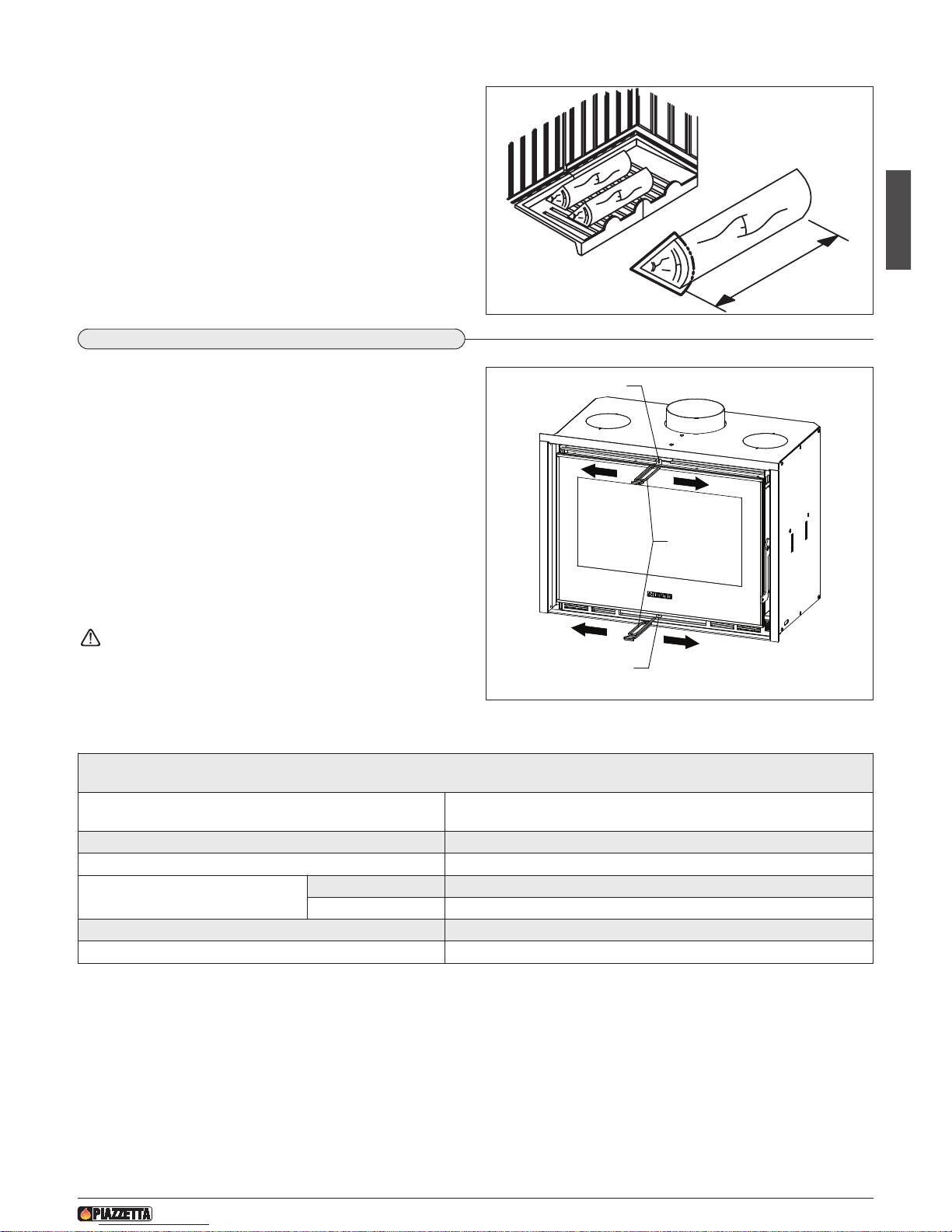
Log size
The size of the wood logs can also affect the efficiency of the product.
-
It is essential for the wood to be arranged on the grate on top of a
layer of embers.
- The logs must not touch the aluker or the glass window nor must
they be put on top of each other. Place the wood as shown in the
figure 29.
-
We therefore recommend using logs of the following size:
perimeter approx. 30/35 cm;
length approx. 20–25–30 cm according to the type of hearth.
P
erimeter
L
e
ng
h
t
Fig. 29
DT20300063-00
DT2012040-00
5.2 COMBUSTION AIR REGULATION
The nominal heat output is determined with the air dampers, which
should be put to the positions given in the table below according to
the stages and the fuels being used.
Since the output also depends on atmospheric and climatic
conditions and therefore on the draught, the most suitable position
will be learned with experience.
Adjust by moving the dampers left or right, as shown in the figure to
the side.
Move to the left to increase and to the right to decrease the air flow.
To make these adjustments and avoid burns, use the straight part of
the door handle tool provided in the kit, inserting it into the hole to
be found in the actual dampers.
To obtain a lower heat output, reduce the amount of fuel and not the
combustion air.
Do not exceed the recommended amount of fuel. Stoking up
with larger amounts of fuel than those recommended in the
table simply increases the heat of the stove, but decreases its
efficiency and increases consumption of wood.
To reduce the heat output, reduce the quantity of fuel and do
not move the air damper.
Close
Open
Close
Open
Secondary air
Primary air
Door handle
Fig. 30
DT2032871-00
Primary and secondary air damper position
IL65/49 – IL65/54 – IL 75/58 – IL75/64
Material to be burned See “FUEL” paragraph
Ignition or lighting stage Fully open
Stage of operation
(nominal heat output)
primary Closed
secondary Open
Maintaining of embers stage See “NIGHT-TIME OPERATION AT MINIMUM” paragraph
Maximum quantity of fuel to be burned See “TECHNICAL DATA” paragraph
Page 24
H07023830 / DT2000612 - Rev. 01
54
English
D
T2010044-04
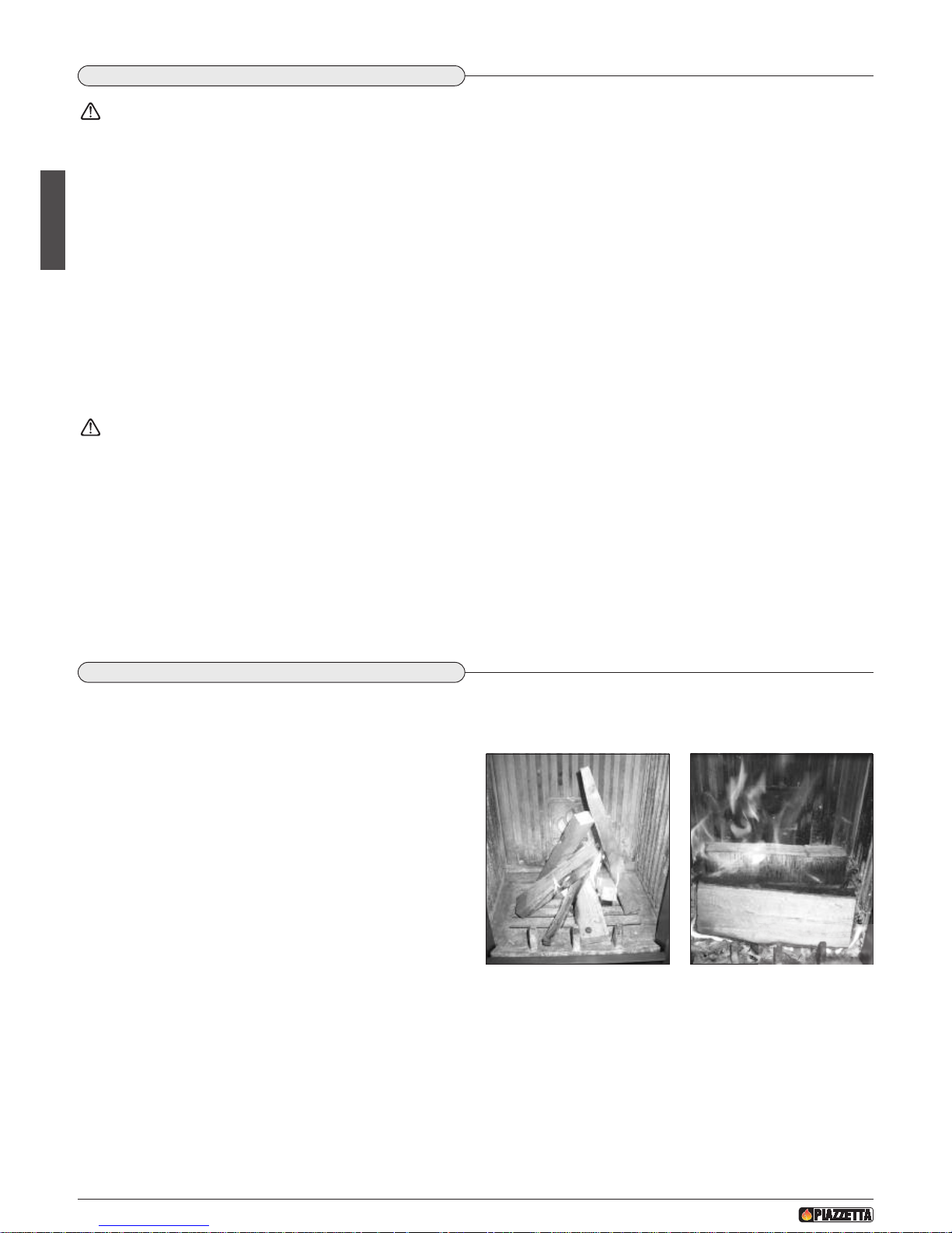
5.4 LIGHTING
When lighting the fire, the grate should be brought quickly to working temperature. If it is done slowly, condensation will inevitably form and
cause blackening of the grate and the glass.
Put the fuel into the grate according to the methods described below:
1. Put the dampers to the open position (MAXIMUM) (see
paragraph “COMBUSTION AIR REGULATION”).
2. Place the material for kindling (paper, firelighter, etc.) in the centre
of the grate and add small pieces of soft wood (fir) in the form of
a pyramid. To light the soft wood quickly, open the door by
approx. two centimetres for 5–10 minutes. (Fig. 31).
3. Once a bed of embers has formed proceed to fill with fuel fig. 32
and to adjust the dampers, referring to the table in the paragraph
“COMBUSTION AIR REGULATION”. Do not open the firebox
during operation.
D
T2010045-03
5
.3 LIGHTING FOR THE FIRST TIME
Before lighting, remove the supplied accessories (see “ACCESSORIES AND EQUIPMENT” paragraph) and flammable elements
from the grate or from the ash drawer and remove any elements of carriage used to protect any part of the stove.
I
f provided in the kit, it is very important to remove the paint spray can, which could explode.
There are two important stages when lighting the appliance for the first time: the operating test and start-up.
1. Operating test
-
Before carrying out the operating test, check that everything has been installed correctly (see section “GENERAL RULES”).
- Start with the lighting stage (see paragraph “LIGHTING”).
- The first load should be reduced by 50% of the normal recommended amount.
Should smoke come out:
• do not open the door of the stove;
• close the combustion air dampers (MINIMUM position) only on appliances with combustion air damper;
• let the fire go out slowly;
• air the room before staying in it;
• check the cause of malfunctioning.
Do not extinguish the fire with water as this could damage the grate
2. Start-up
- During this first time of operation it is recommended to use the appliance at minimum capacity, stoking the grate for at least the first
day with only 50% of the logs usually indicated as normal.
- Keep the air dampers in the operating position (except for lighting), see paragraph “COMBUSTION AIR REGULATION”.
- This stage allows all the parts to settle down and fumes caused by paints/varnishes, greases or oily liquids used in manufacture to
disappear.
- Air the room well in this initial stage.
- This procedure must be carried out with the forced ventilation system turned off.
After this, the appliance will no longer emit odours due to paint evaporation and must only be stoked up with the indicated nominal amounts.
Fig. 31
DT2030064-00
Fig. 32
DT2030065-00
Page 25
H07023830 / DT2000612 - Rev. 01
55
English
D
T2010048-00
5.7 OPERATION UNDER ADVERSE WEATHER CONDITIONS
During the intermediate seasons with adverse weather conditions or when outdoor temperatures are higher, a sudden rise can cause malfunctioning of the draught, thereby impeding proper smoke discharge. In this case the grate must be loaded with only a little wood and the
primary air damper be set fully open so that the wood burns faster and thereby stabilises the draught.
DT2010051-00
5.8 OVERHEATING AND EXTINGUISHING
In the event of overheating or if some appliance parts or the flue turn red:
- immediately stop the supply of fuel;
- do not open the stove door;
- close the air dampers (MINIMUM position);
The fire will go out due to lack of air.
When the appliance has cooled down, find the cause of the problem and if necessary call in specialised personnel.
In the event of fire, extinguish with a fire extinguisher.
Do not extinguish the fire with water.
Air the room well before using it again in order to get rid of any smoke and combustion gases.
DT2010046-00
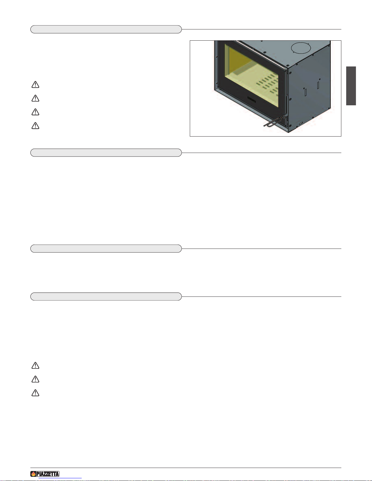
5.5 OPENING THE DOOR
The door must remain closed while the stove is alight, otherwise it
could damage the inside of the stove.The door must be opened
s
lowly, holding it slightly ajar for a moment before opening it completely. Open the door when the flame has died down and certainly
never when the flame is very intense.
Always use the hexagonal door handle tool provided.
Always use the glove provided.
Do not slam the door shut otherwise the glass could break.
The glove is not designed for picking up burning embers!!!
D
T2010047-00
5.6 NIGHT TIME OPERATION AT MINIMUM
After normal operation during the day, the appliance may continue to operate for a few hours at night.
When stoking up the fire for the last time in the evening, ensure that the bed of embers is sufficient, put the wood in the grate and then set
the combustion air dampers to minimum. Night time operation of the stove at minimum depends on the type of wood (a very hard wood is
recommended), the flue draught and the weather.
The amount of wood to put on and the necessary adjustment of combustion air flow will be learned with experience (see the paragraph
“COMBUSTION AIR REGULATION”).
The next morning, start up the fire at maximum to burn off any creosote formed during the night. Creosote deposits start to form when the
flue temperature falls to below 150 °C. To prevent this from happening it is important to try to maintain the grate of the appliance at normal
working temperature (rated heating efficiency phase) as long as possible.
Prolonged operation of the stove at minimum could require more frequent cleaning of the grate and the flue.
Fig. 33
D
T2033049-00
Page 26
H07023830 / DT2000612 - Rev. 01
56
English
6.0 MAINTENANCE
D
T2010463-00
D
T2010058-00
6.1 PERIODIC CONTROL
Check for any formation of creosote in the pipes connecting to the flue and inside the flue during the seasons when the appliance is in operation, inspecting them at least once every two months.
The combustion of the wood (especially if moisture content is higher than 30%) produces pitch and other organic vapours that give rise to
creosote. The formation of creosote causes fouling, which obstructs the flue and the passage of smoke.
“Creosote” is inflammable and can catch fire, causing serious damage to both the flue and to the structure of the dwelling.
Only use recommended fuels (see “FUEL” paragraph).
If creosote has accumulated, it must be removed to reduce the risk of fire and to improve heat exchange.
The following must be free from obstruction and inspected at least once every two months:
- the flueways (connection to the flue, flue pipe, chimney stack);
- the fresh air intake;
- the appliance hearth (correct position of the plates, the ash tray, the grate and grid, deflectors, smoke dampers, etc);
- the ventilation system (apertures, air ducts, grilles) if installed.
Check that the automatic door closing system and the air dampers are in proper working order.
Maintenance of all the above heating system must be carried out at least once a year before the season when it will be used. We
also recommend periodically checking the whole heating system during the period of operation until the time when it will not be
used for several months.
D
T2010061-01
6.2 CLEANING THE PAINTED METAL PARTS
When cleaning the parts of the product in painted metal use a soft cloth moistened with water.
Never clean metallic parts using alcohol, solvents, petroleum-based agents, acetones or other degreasing or abrasive substances.
In the event of such substances being used the manufacturer declines all responsibility for damage caused.
Discolouration of metallic parts may be the result of improper use.
DT2010062-01
6.3 CLEANING THE GLASS (DAILY)
The glass should be cleaned when cold using ammonia-based degreasing agents and not corrosive substances such as solvents.
If the appliance is very slow to heat up in the ignition phase due to fuel that isn’t completely dry, this is likely to cause a build-up of tar on
the glass. This will eventually burn off when the secondary air supply is open (if the appliance is equipped accordingly) or when the appliance is functioning at full capacity. If the tar is left to build up over a long period it will require more effort to remove it. We therefore rec-
ommend that the glass be cleaned daily before lighting the stove.
IN CASE OF BREAKAGE: Every one of our hearths comes with a door fitted with a 4 mm thick glass panel resistant to a thermal shock of
750°C. This can only be broken by a heavy impact, such as banging the door too hard.
In case of breakage replace with original Gruppo Piazzetta S.p.A parts only.
Do not use any material that could scratch or spoil the glass, as scratches may develop into cracks or breaks
•
Maintenance is to be considered compulsory for correct and efficient stove operation. If maintenance is not carried out with the recommended frequency, stove performance could suffer. The manufacturer will not be responsible for stove deterioration or malfunction if due
to poor maintenance.
• All maintenance work (cleaning, any replacements, etc.) must be carried out when the stove is shutdown and cold.
• Do not use materials that could scratch or damage the glass, since scratches could become cracks. Under no circumstances use abrasive
s
ubstances.
D
T2010057-02
Page 27
EnglishEnglish
H07023830 / DT2000612 - Rev. 01
57
English
D
T2010049-04
6.5 DISPOSAL OF ASHES
Ash from natural (non-treated) wood burned in stoves or open fireplaces is composed mainly of calcium, silicon, potassium and magnesium
oxides. The ashes can therefore be used as a fertiliser for plants or in the garden, albeit not exceeding 2.6 kg per 10m2 annually.
The ashes should be placed in a metal container with a sealed cover. The sealed container should be placed on a non-combustible
surface at a safe distance from combustible materials until the cinders have been completely extinguished.
Only when they have been fully extinguished can the ashes be thrown away with organic waste, assuming that nails or other nonorganic material are not present.
D
T2011732-02
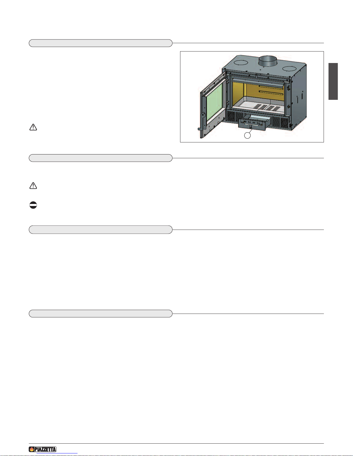
6.4 CLEANING THE GRATE AND THE ASH DRAWER
T
he grate and the ash drawer must be cleaned daily. Using the grate
for a whole day contributes to the accumulation of ash or residual
combustion products.
If cleaning is not done regularly there will be an excess of residues,
which will affect appliance efficiency.
C
lean the grate with a vacuum cleaner suitable for holding ash.
The ash drawer [A] also needs emptying and cleaning regularly,
because if it fills up and obstructs the grate grid it will cause
appliance malfunction.
Should the grid become clogged, clean.
When replacing the ash drawer, make sure that it is fully
fitted into the stove.
D
T2010064-00
6.6 CLEANING ALUKER
®
The interior of the unit has been constructed from an innovative material called “Aluker®”.
Aluker®is based on substances that are completely non-toxic and is heat-resistant up to 1400°C.
In spite of its considerable strength it is not recommended that you throw large pieces of wood forcefully
against the bricks.
Aluker®darkens when the stove is first lit but returns to its natural colour gradually as the bricks warm up.
Some advice for optimum use of Aluker®bricks:
- Don’t use water to put out the fire - leave the bricks to cool by themselves;
- Don’t scratch Aluker®bricks with metal objects;
To clean Aluker®bricks use an ordinary brush.
DT2010165-00
6.7 SEAL CONTROL
Proper tightness of the door seal is essential for optimal product performance. It is therefore recommended that the seals be checked periodically or after a long period of use for signs of wear or damage. If necessary replace them using Gruppo Piazzetta S.p.A. original spare
parts.
A
F
ig. 34
D
T2033050-00
Page 28
English
58
H07023830 / DT2000612 - Rev. 01
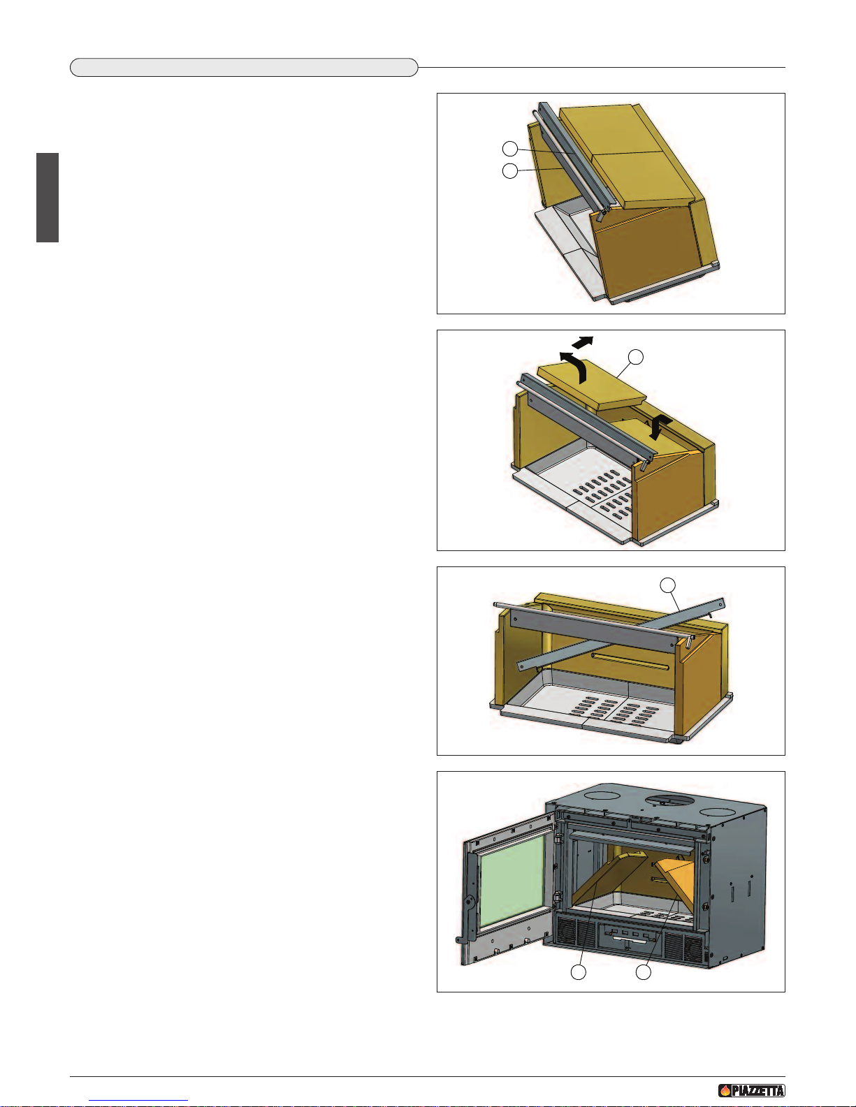
Until you are familiar with the movements to be made, it is advisable
to proceed very carefully.
•
Open the firebox door.
• Shift the baffle plate support [A] forwards towards the smoke dam-
per [B], while supporting the actual baffle plates with the other
hand. (Fig. 35)
• Lift one of the two baffle plates [C] by about three centimetres, then
shift it sideways (outwards) and to the rear; lower the other baffle
plate into the space that has been created and remove it from the
firebox. (Fig. 36)
• Now shift the second baffle plate [C] towards the centre and, kee-
ping it slightly raised, remove it from the firebox.
• Remove the baffle plate support [A] by turning its right end towards
the rear top right corner of the firebox and tilting the left end towards the grate. (Fig.37)
• Turn the smoke damper [B] by hand a little further than the “closed”
position, then tilt the top part of the left side panel [D] inwards until
reaching an angle that allows it to be removed through the firebox
opening. Remove the right side panel [E] in the same way. (Fig. 38)
DT2012128-00
6.8 REMOVING THE ALUKER INTERIOR AND GRATE
A
B
Fig. 35
D
T2033051-00
C
Fig. 36
D
T2033052-00
A
Fig. 37
DT2033053-00
D E
Fig. 38
DT2033054-00
Page 29
English
59
H07023830 / DT2000612 - Rev. 01
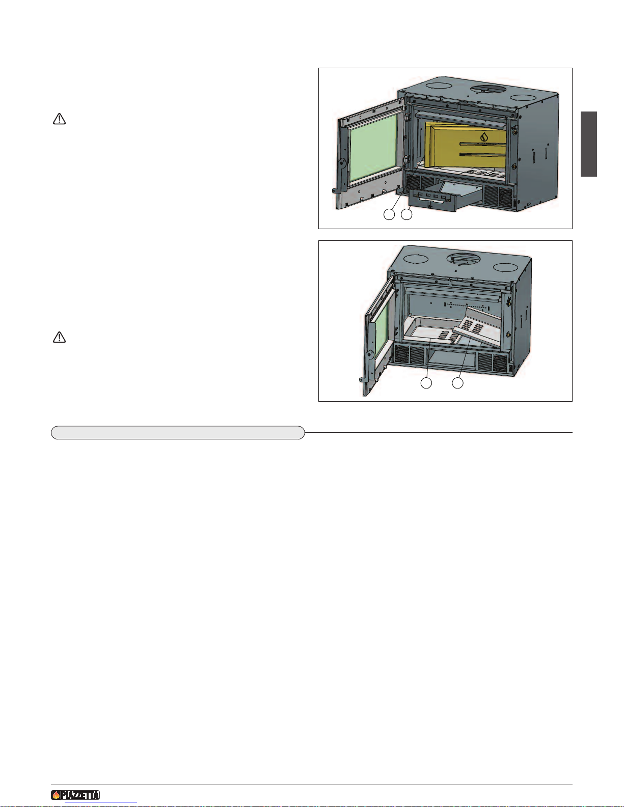
• Rotate the back panel [F] by about 90° and then remove it.
(Fig. 39)
Given the weight and size of the piece, take great care!!
• Remove the ash drawer [G]. (Fig. 39)
• Tilt the right part of the grate [H] and remove it (Fig. 40); to make
this movement easier, insert a hand into the space left free by the
ash drawer and push from below.
• Remove the left part of the grate [I] in the same way.
• Clean the firebox interior and then refit everything in the reverse
order to the steps given above for removal.
For constructional reasons the two parts of the grate are not
symmetrical; always remove the right part first and always refit
the left part first.
F
G
Fig. 39
D
T2033055-00
HI
Fig. 40
D
T2033056-00
D
T2010068-00
6.9 SHUTTING DOWN
Before any long period during which the stove will be inactive we recommend that you carry out a thorough cleaning, thereby avoiding encrustations and oxidations which will be difficult to clean later. We also recommend that as a preventative measure you carry out a general
checkup as outlined in the paragraph headed “PERIODIC CONTROL”.
After a period of inactivity problems relating to the expansion of parts or the release of odorous gases may arise. We therefore recommend
that upon restarting the unit you do not immediately run it at full power. Nor should you activate the ventilation system until the odorous gases
have dispersed. This problem can be dealt with by simply airing the room.
Page 30
H07023830 / DT2000612 - Rev. 01
60
English
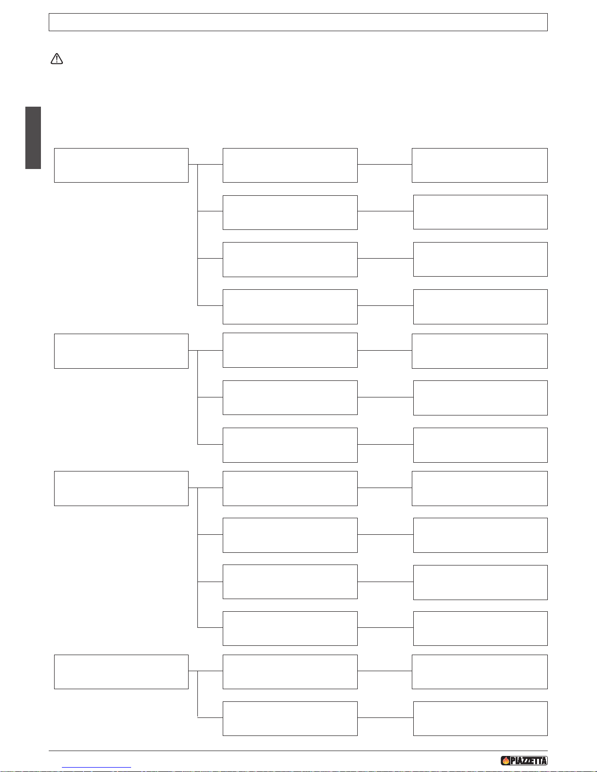
Some of the above problems could be resolved by following the instructions. Only qualified persons must carry out work on the
stove and only when it is cold and disconnected from the power supply (pull out the plug).
Unauthorised tampering with the appliance or use of other than original spare parts invalidates the warranty and relieves the
m
anufacturer of all and any liability.
The manufacturer shall not be liable for any problems caused by lack of or inefficient maintenance or by failure to comply with the
instructions in the product installation and operating guide.
7.0 TROUBLESHOOTING
DT2010069-00
P
roblem Cause Remedy
The window becomes
excessively dirty
Lack of draught Check the smoke/gas discharge pipe
W
et wood
Use dry wood
Use of mediocre or poor class fuels
Change the type of fuel
(See “FUEL” paragraph)
Not enough combustion air Open the air dampers further
Condensation forms
Section of flue too large
Reduce the section by inserting a well
insulated pipe with suitable section
inside the flue
Flue not adequately insulated
Clad the flue with hollow tiles or
other insulating materials
Slow combustion and therefore low
smoke temperature
Burn smaller and dry logs.
Open the primary air damper further
Smoke comes out of the fireplace in
adverse weather conditions
Chimney stack has no down-draught
cowl
Replace the chimney stack with one
that has a down-draught cowl
Flue not suitably insulated
Clad the flue with hollow tiles or
other insulating materials
Difficulty in lighting Closed air damper
Put the combustion air (intake)
dampers to maximum position
Logs too large
Use smaller logs
Wood too wet
Burn drier wood
Lack of draught Check the smoke/gas discharge pipe
Page 31
H07023830 / DT2000612 - Rev. 01
61
English
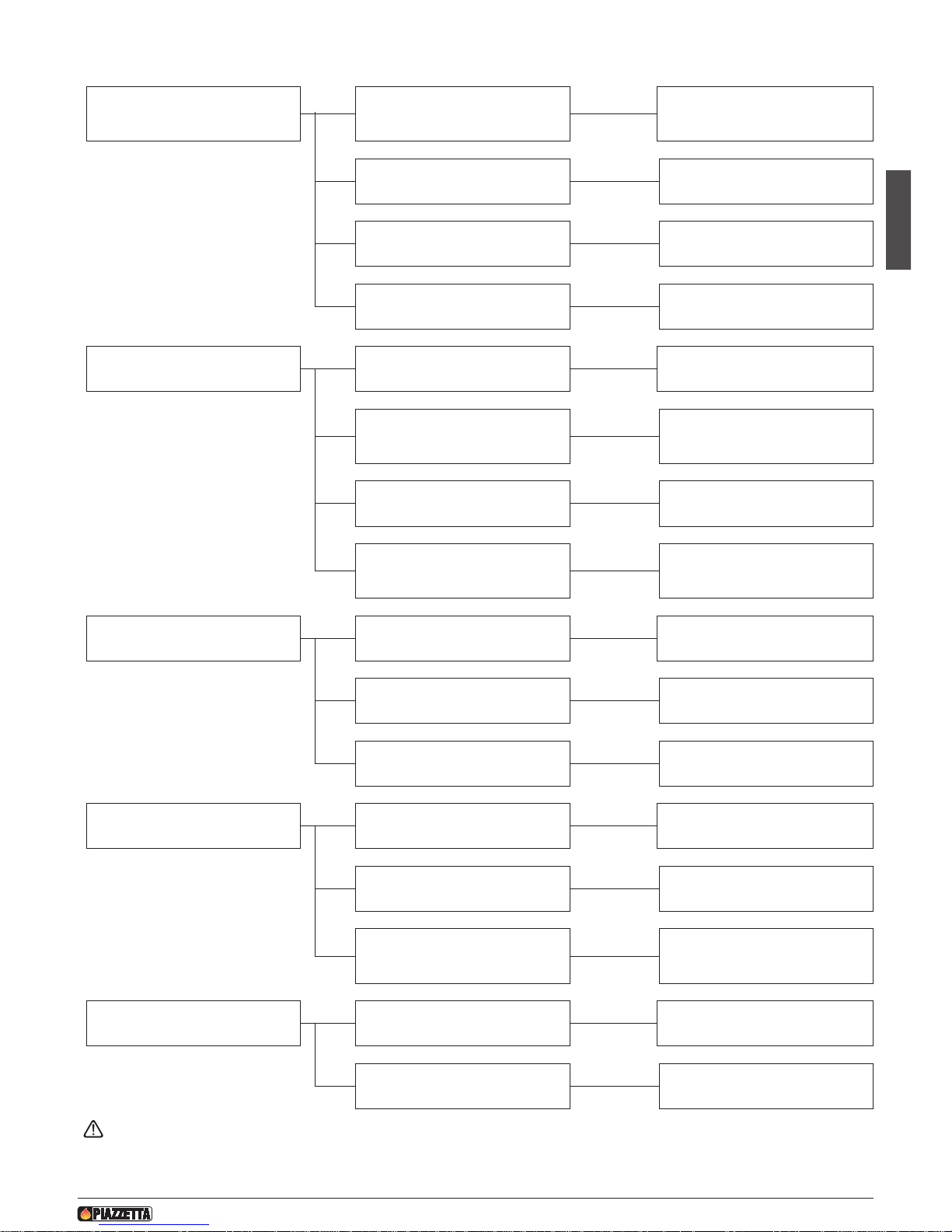
Problem Cause Remedy
T
he grate does not warm
Quantity of wood less than necessary
for nominal efficiency
Use the quantity of wood indicated in
t
he instructions (See “TECHNICAL
DATA” paragraph)
Undersized grate for the environment
to be heated
Integrate with another product
Inadequate insulation for the environment in which the fireplace is installed
Insulate well with suitable materials
Oversized fresh air intake Decrease the intake section
Too little and only lukewarm air flows
from the outlets
P
ipework not insulated
S
uitably insulate
Pipework too long or with too many
bends
Change the path, complying with the
ventilation kit instruction booklet
Too many branches
Change the path
Environment too large for capacity of
the fan and power of the product
Heat fewer rooms or use the stove as
a supplementary source of heat
The fan does not work (*) Incorrect connection to power supply
Correct the connection according to
the assembly diagram
Electronic regulator damaged Replace the regulator
Power failure Power the appliance
Noisy fan (*) Presence of dust or similar in the fan Clean the fan
Vibrations Check fan position
Worn rotating parts
Maintain or replace worn parts
Replace the fan
Smoke comes out upon opening the
door
Door opened too fast
Keep the door just ajar for a few
seconds before fully opening
There are still flames
Only open the door when just embers
remain in the grate
(*) Pursuant to current regulations on the safety of electrical equipment, you must contact a Piazzetta After-Sales Service Centre
or a qualified electrician for all and any work connected with installation, maintenance or servicing that involves access to electrical parts.
Page 32

62
H07023830 / DT2000612 - Rev. 01
Page 33

63
H07023830 / DT2000612 - Rev. 01
Page 34

www.miotto.it
Gruppo Piazzetta S.p.A. Technical Department - cod. H07023830 / DT2000612 - Rev. 01 - (08/2010)
Via Montello, 22
31011 Casella d’Asolo (TV) - ITALY
Tel. +39.04235271 - Fax +39.042355178
www.piazzetta.it
e-mail: [email protected]
N° matricola prodotto, da comunicare al Centro Assistenza Tecnica
del Gruppo Piazzetta in caso di richiesta assistenza.
Product serial number, to be quoted when requesting service
from the Gruppo Piazzetta After-Sales Service Centre.
IT
UK
IT
 Loading...