

Page 1

Il libretto istruzioni é parte integrante del prodotto. - The instruction booklet is an integral part of the product.
Italiano
English
istruzioni per l’installazione
l’uso e la manutenzione
installation, use and
maintenance instructions
Stufa / Stove
e911 e912
e915 e917
e918 e920
e922 e923
Page 2

2
Italiano
Gentile Cliente,
La ringraziamo per aver preferito uno dei nostri prodotti, frutto di lunga esperienza e di una continua ricerca per un prodotto superiore
in termini di sicurezza, affidabilità e prestazioni.
In questo manuale troverà tutte le informazioni ed i consigli utili per poter utilizzare il suo prodotto nel massimo della sicurezza ed
efficienza.
DT2010001-00
INDICAZIONI IMPORTANTI
DT2010021-01
NORMATIVE DI RIFERIMENTO
DT2010028-02
Per i termini, limiti ed esclusioni fare riferimento al certificato di garanzia allegato al prodotto.
Il costruttore nell’intento di perseguire una politica di costante sviluppo e rinnovamento del prodotto può apportare, senza preavviso
alcuno, le modifiche che riterrà opportune.
Questo documento è di proprietà del Gruppo Piazzetta S.p.A.; non può essere divulgato totalmente o in parte a terzi senza autorizzazione scritta
del Gruppo Piazzetta S.p.A. Il Gruppo Piazzetta S.p.A. si riserva i diritti a rigore di legge.
• Questo libretto di istruzioni è stato redatto dal costruttore e
costituisce parte integrante del prodotto. Le informazioni in esso
contenute sono indirizzate all’acquirente, e a tutte quelle persone
che a vario titolo concorrono all’installazione, all’uso e alla
manutenzione del prodotto.
• Leggete con attenzione le istruzioni e le informazioni tecniche
contenute in questo manuale, prima di procedere all’installazione,
all’utilizzo e a qualsiasi intervento sul prodotto.
• L’osservanza delle indicazioni contenute nel presente libretto
istruzioni garantisce la sicurezza alle persone e cose; assicura
l’economia di esercizio ed una più lunga durata di funzionamento.
• Il Gruppo Piazzetta S.p.A. declina ogni responsabilità per danni
causati dalla inosservanza alle norme di installazione uso e
manutenzioni indicate nel libretto di istruzioni, per modifiche del
prodotto non autorizzate o ricambi non originali.
• L’installazione e l’utilizzo del prodotto deve essere fatta in
conformità con le istruzioni del fabbricante, e nel rispetto delle
normative europee, nazionali e dei regolamenti locali.
• Prima di installare il prodotto leggere, se previsti, tutti gli
eventuali libretti istruzione inerenti a: rivestimento, kit
ventilazione, altri accessori.
• L’installazione del prodotto non deve essere effettuata a ridosso
di pareti in legno o di materiale infiammabile. Per una corretta
installazione è necessario osservare quanto segue alla sezione
“Distanze di sicurezza”.
• Controllare l’esatta planarità del pavimento dove verrà installato il
prodotto.
• Nel movimentare le parti in acciaio del rivestimento si consiglia di
utilizzare guanti puliti in cotone, evitando di lasciare impronte
difficili da togliere per la prima pulizia.
• Il montaggio della stufa deve essere eseguito da almeno due
persone.
• Sospendere l’utilizzo del prodotto in caso di guasto o di
malfunzionamento.
UNI EN 832 . . . . . . . . . . . . . . . . . . . . . . . . Prestazione termica degli edifici - Calcolo del fabbisogno di energia per il riscaldamento
UNI EN 13240 . . . . . . . . . . . . . . . . . . . . . . Stufe a combustibile solido – Requisiti e metodi di prova
UNI 10683 . . . . . . . . . . . . . . . . . . . . . . . . . Generatori di calore alimentati a legna o da altri biocombustibili solidi
UNI EN 13384 . . . . . . . . . . . . . . . . . . . . . . Camini - Metodi di calcolo termico e fluido dinamico
UNI 10847 . . . . . . . . . . . . . . . . . . . . . . . . . Impianti fumari singoli per generatori alimentati con combustibili liquidi e solidi
Manutenzione e controllo - Linee guida e procedure
UNI EN 1856-1-2 . . . . . . . . . . . . . . . . . . . . Camini – Requisiti per camini metallici
UNI EN 1443 . . . . . . . . . . . . . . . . . . . . . . . Camini – Requisiti generali
UNI 7129 . . . . . . . . . . . . . . . . . . . . . . . . . . Impianti a gas per uso domestico alimentati da rete di distribuzione
DIN 18 891 . . . . . . . . . . . . . . . . . . . . . . . . Stufe a camino per combustibili solidi
DIN 51731 classe di misura HP2 . . . . . . . . Combustibili
Page 3
INDICE
DT2010187-01
Cap. Titolo Pag. cod. txt
1.0 Norme generali 4 DT2010444-00
1.1 Camino o canna fumaria singola 5 DT2010024-01
1.2 Ispezione per raccolta fuliggine 5 DT2010031-00
1.3 Comignolo 6 DT2010025-00
1.4 Presa d’aria esterna 7 DT2010026-00
1.5 Ambiente di installazione 8 DT2010215-01
1.6 Portata del solaio 8 DT2010032-00
1.7 Capacità di riscaldamento 8 DT2010130-00
1.8 Distanze di sicurezza 9 DT2010034-00
1.9 Collegamento alla canna fumaria 9 DT2010445-00
1.10 Prevenzione degli incendi domestici 12 DT2010027-00
2.0 Caratteristiche e dati tecnici 13 DT2010446-02
2.1 Descrizione dell’apparecchio 13 DT2010847-00
2.2 Accessori 16 DT2010452-00
2.3 Caratteristiche 16 DT2010450-00
2.4 Dati di identificazione del prodotto 16 DT2010041-04
2.5 Dati tecnici 17 DT2010451-01
2.6 Dimensioni e911 18 DT1020016-00
2.7 Dimensioni e912 18 DT1020017-00
2.8 Dimensioni e915 18 DT1020095-00
2.9 Dimensioni e917 18 DT1020232-00
2.10 Dimensioni e918 19 DT1020270-00
2.11 Dimensioni e920 19 DT1020015-00
2.12 Dimensioni e922 19 DT1020231-00
2.13 Dimensioni e923 19 DT1020271-00
3.0 Uso 20 DT2010453-00
3.1 Combustibile 20 DT2010043-00
3.2 Regolazione aria comburente 21 DT2010462-00
3.3 Prima accensione 21 DT2010045-01
3.4 Accensione 22 DT2010044-02
3.5 Apertura della porta 22 DT2010046-00
3.6 Funzionamento notturno al minimo 23 DT2010047-00
3.7 Funzionamento in condizioni atmosferiche avverse 23 DT2010048-00
3.8 Surriscaldamento e spegnimento 23 DT2010051-00
3.9 Umidificatore 23 DT2010464-00
3.10 Uso del forno 23 DT2010395-00
4.0 Manutenzione 24 DT2010463-00
4.1 Controllo periodico 24 DT2010058-00
4.2 Pulizia del rivestimento in ceramica 24 DT2010059-01
4.3 Pulizia delle parti in acciaio inox 24 DT2010060-00
4.4 Pulizia delle parti in metallo verniciato 24 DT2010061-01
4.5 Pulizia del vetro 24 DT2010062-01
4.6 Rimozione deflettori 25 DT2010443-00
4.7 Chiusura automatica della porta 25 DT2010442-00
4.8 Pulizia del focolare e del cassetto cenere 26 DT2010063-00
4.9 Pulizia dell’Aluker
®
26 DT2010064-00
4.10 Pulizia del ventilatore 26 DT2010065-01
4.11 Verifica guarnizione 26 DT2010165-00
4.12 Inattività del prodotto 26 DT2010068-00
4.13 Smaltimento delle ceneri 26 DT2010049-01
5.0 Principali anomalie 27 DT2010069-00
Dichiarazione di conformità stufa e911 57 DT2010702-00
Dichiarazione di conformità stufa e915-e917-e918 58 DT2010703-00
Dichiarazione di conformità stufa e912-e920-e922-e923 59 DT2010704-00
Questo libretto cod. H07020320 / DT2000212 - Rev. 01-(05/2007) è composto da 60 pagg.
Italiano
3
Page 4
4
Italiano
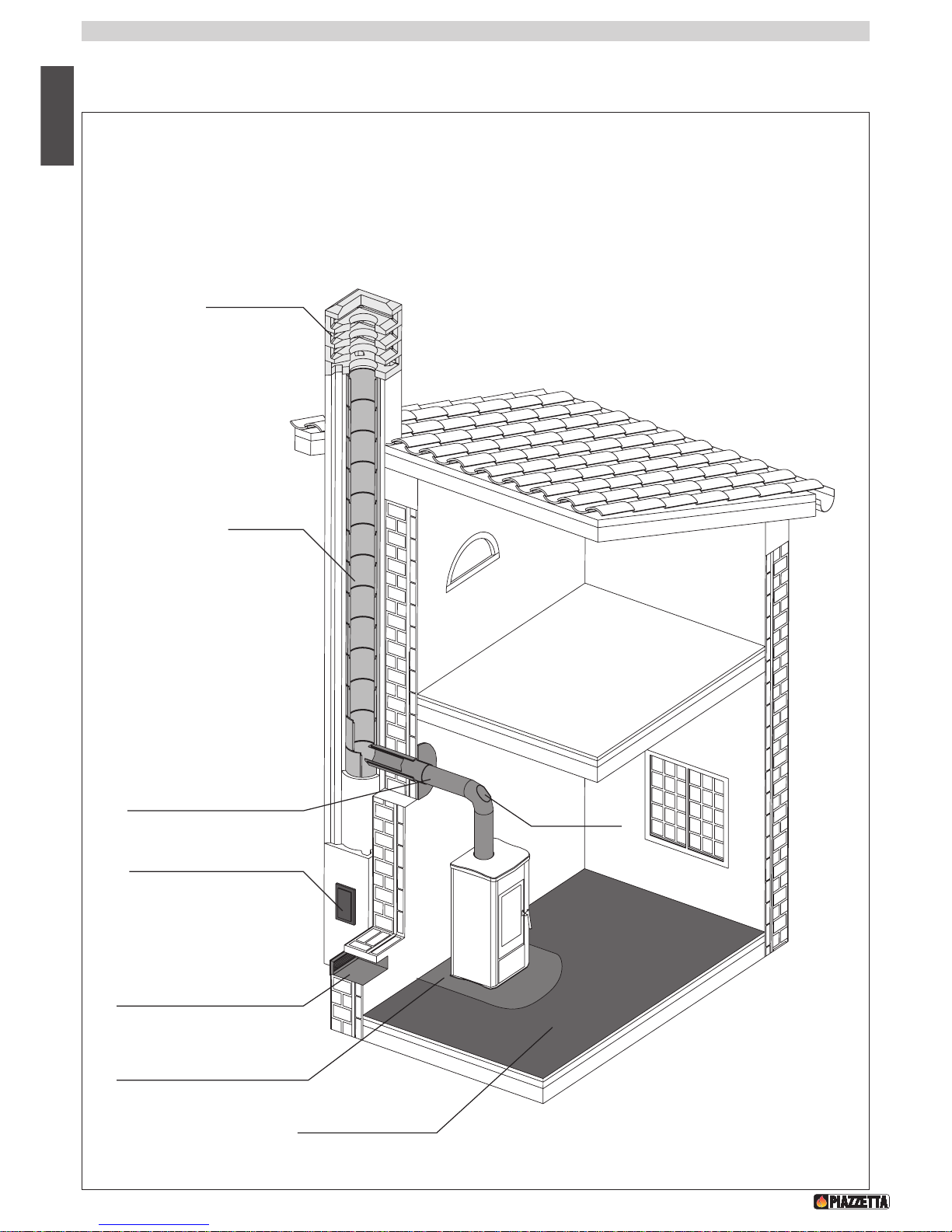
1.0 NORME GENERALI
DT2010444-00
DT2030048-00
COMIGNOLO
CANNA
FUMARIA
COLLEGAMENTO
ALLA CANNA FUMARIA
ISPEZIONE PER
RACCOLTA FULIGGINE
PRESA D'ARIA ESTERNA
VERIFICA
PORTATA SOLAIO
DISTANZE DI SICUREZZA
ISPEZIONE
Controllare che tutte le voci qui sotto elencate siano conformi all’installazione con il vostro prodotto.
Fig. 1
Page 5
Italiano
5
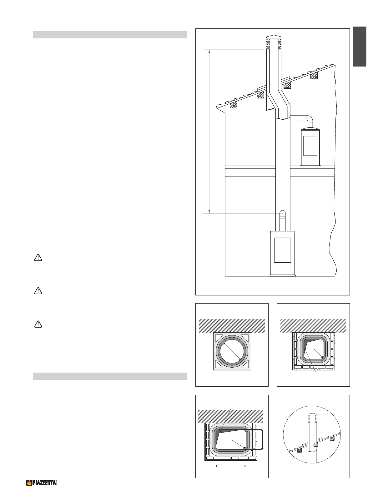
NO
X
Minimo 3,5 m
MAX 45°
NO
1.1 Camino o canna fumaria singola - Fig. 2÷6
Ogni apparecchio a tiraggio naturale deve avere un condotto
verticale, denominato canna fumaria per scaricare all’esterno i fumi
prodotti della combustione.
La canna fumaria dovrà rispondere ai seguenti requisiti:
- alle norme in vigore nel luogo di installazione dell’apparecchio;
- essere a tenuta dei prodotti della combustione, impermeabile,
adeguatamente isolata e coibentata, costruita con materiali
resistenti alla corrosione dei fumi e alle sollecitazioni
meccaniche;
- essere collegata da una sola stufa, caminetto, o cappa aspirante
(fig.2);
- essere ben dimensionata, di sezione interna costante libera,
uguale o superiore del diametro del tubo di scarico fumi della
stufa e di altezza non inferiore a 3,5 m (fig.2);
- essere prevalentemente di andatura verticale con una deviazioni
dall’asse non superiori a 45° (fig.2);
- essere adeguatamente distanziata da materiali combustibili o
infiammabili mediante intercapedine d’aria o opportuno isolante;
- essere di sezione interna uniforme, preferibilmente circolare: le
sezioni quadrate o rettangolari devono avere spigoli arrotondati
con raggio non inferiore a 20mm; avente un rapporto massimo
tra i lati di 1,5 (fig.3-4-5);
- le pareti devono essere il più possibili lisce e senza
restringimenti, le curve regolari e senza discontinuità (fig.6).
È proibito praticare aperture fisse o mobili sulla canna
fumaria per collegare apparecchi diversi da quello a cui è
asservita.
È vietato far transitare all’interno della canna fumaria,
sebbene sovradimensionata, altri canali di adduzione
d’aria e tubazioni ad uso impiantistico.
Se la canna fumaria dovesse essere male dimensionata o
installata nella inosservanza di quanto citato sopra il
Gruppo Piazzetta S.p.A. declina ogni responsabilità ad un
cattivo funzionamento del prodotto o al danneggiamento di
cose, persone o animali.
1.2 Ispezione per raccolta fuliggine - Fig. 1
- La canna fumaria deve essere dotata di una camera di raccolta di
materiali solidi ed eventuali condense situata sotto l’imbocco del
raccordo, in modo da essere facilmente apribile ed ispezionabile
con uno sportello a tenuta d’aria (fig.1).
- Le curve di collegamento alla canna fumaria devono essere
dotate di ispezione che consentano: il controllo, la pulizia, e la
manutenzione dell‘impianto.
Ø
DT2030050-00
DT2030049-00
Fig. 3
P
R (min. 20)
L (<_ 1,5 x P)
Accumulo di Creosoto
DT2030189-00
Fig. 5
R (min. 20)
Accumulo di Creosoto
DT2030188-00
Fig. 4
Fig. 2
DT2030190-00
Fig. 6
Page 6
6
Italiano
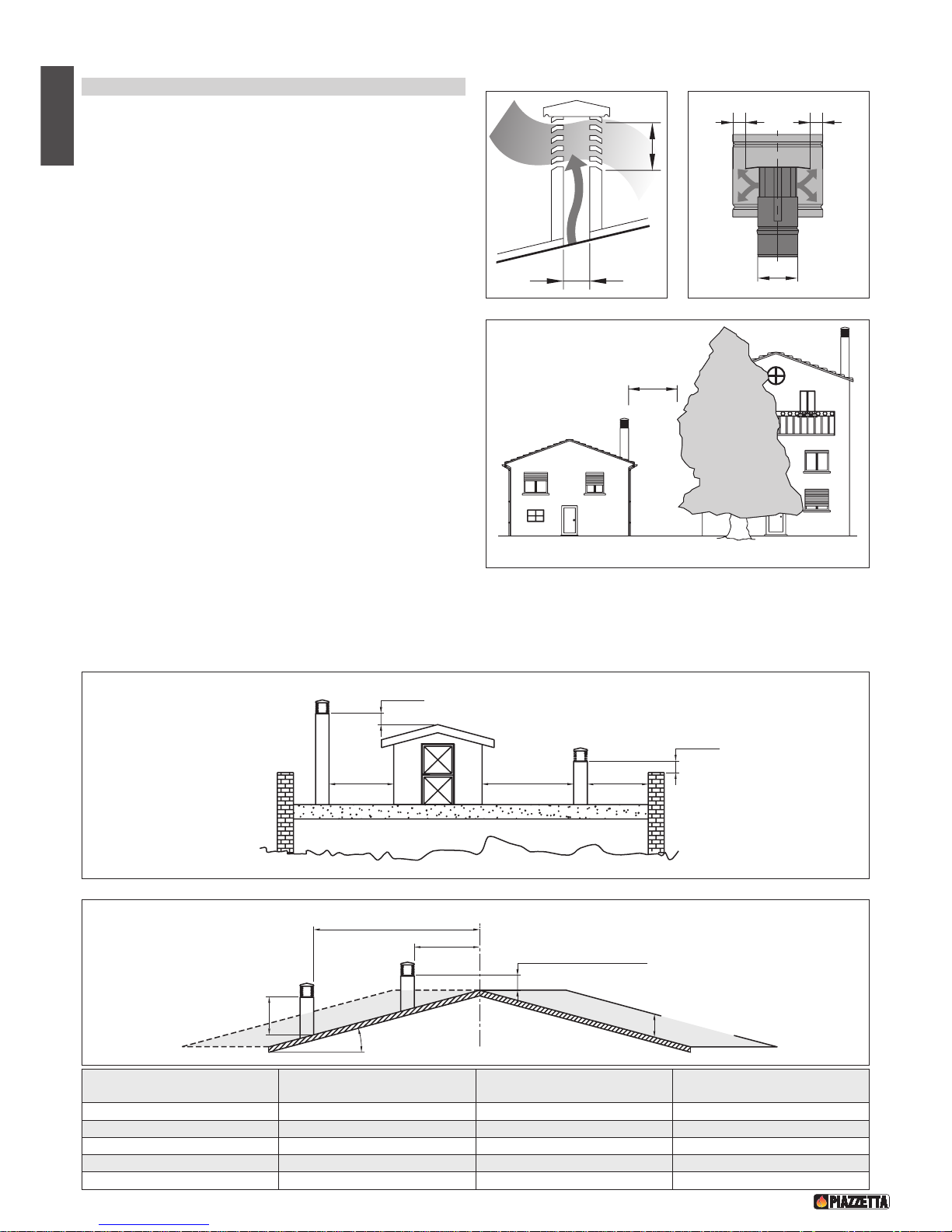
1.3 Comignolo - Fig. 7 ÷ 11
La canna fumaria deve essere dotata sulla sommità di un
dispositivo, denominato comignolo, atto a facilitare la dispersione
in atmosfera dei prodotti della combustione.
Il comignolo dovrà rispondere ai seguenti requisiti:
-
avere sezione e forma interna equivalente a quella della canna fumaria A;
- avere sezione utile di uscita B non minore del doppio di quella
della canna fumaria A;
- il tratto di canna fumaria che fuoriesce dal tetto o che rimane a
contatto con l’esterno (per esempio nel caso di solaio aperto), deve
essere rivestito con elementi in laterizio e comunque ben isolato;
- essere costruito in modo da impedire la penetrazione nella canna
fumaria della pioggia, della neve, di corpi estranei ed in modo che in
caso di venti da ogni direzione ed inclinazione sia comunque assicurato
lo scarico dei prodotti della combustione (comignolo antivento);
- eventuali fabbricati od altri ostacoli che superano l’altezza del
comignolo non dovranno essere a ridosso del comignolo stesso (fig.9);
- il comignolo deve essere posizionato in modo da garantire un’adeguata
dispersione e diluizione dei prodotti della combustione e comunque al
di fuori della zona di reflusso. Tale zona ha dimensioni e forme diverse
in funzione dell’angolo di inclinazione della copertura, per cui risulta
necessario adottare le altezze minime riportate in fig.10-11;
Esempio: Verificare l’inclinazione del tetto (colonna α), e la
distanza prevista del comignolo dall’asse del colmo (colonna A), se
la distanza è maggiore di “A” l’altezza del comignolo si legge nella
(colonna H); Se la distanza è minore di “A” il comignolo deve
oltrepassare il colmo di 0,5 metri.
6-8 m
DT2030052-00
Fig. 9
TETTO PIANO
0.50 m
0.50 m
maggiore 5 m
pari o minore
5 m
pari o minore
5 m
DT2030053-00
Fig. 10
TETTO INCLINATO
0.50 m oltre il colmo
altezza zona di
reflusso Z
asse colmo
distanza maggiore A
α
H min.
distanza
min. uguale A
Fig. 11
Inclinazione del tetto
Larghezza orizzontale zona
di reflusso dall’asse del colmo
Altezza minima sbocco
dal tetto
Altezza zona di reflusso
α
A H minimo Z
15° 1,85 m 1,00 m 0,50 m
30° 1,50 m 1,30 m 0,80 m
45° 1,30 m 2,00 m 1,50 m
60° 1,20 m 2,60 m 2,10 m
A
B*
* B equivale al
doppio di A
DT2030051-00
Fig. 7
A
BB
DT2030191-00
Fig. 8
DT2030192-00
Page 7
Italiano
7
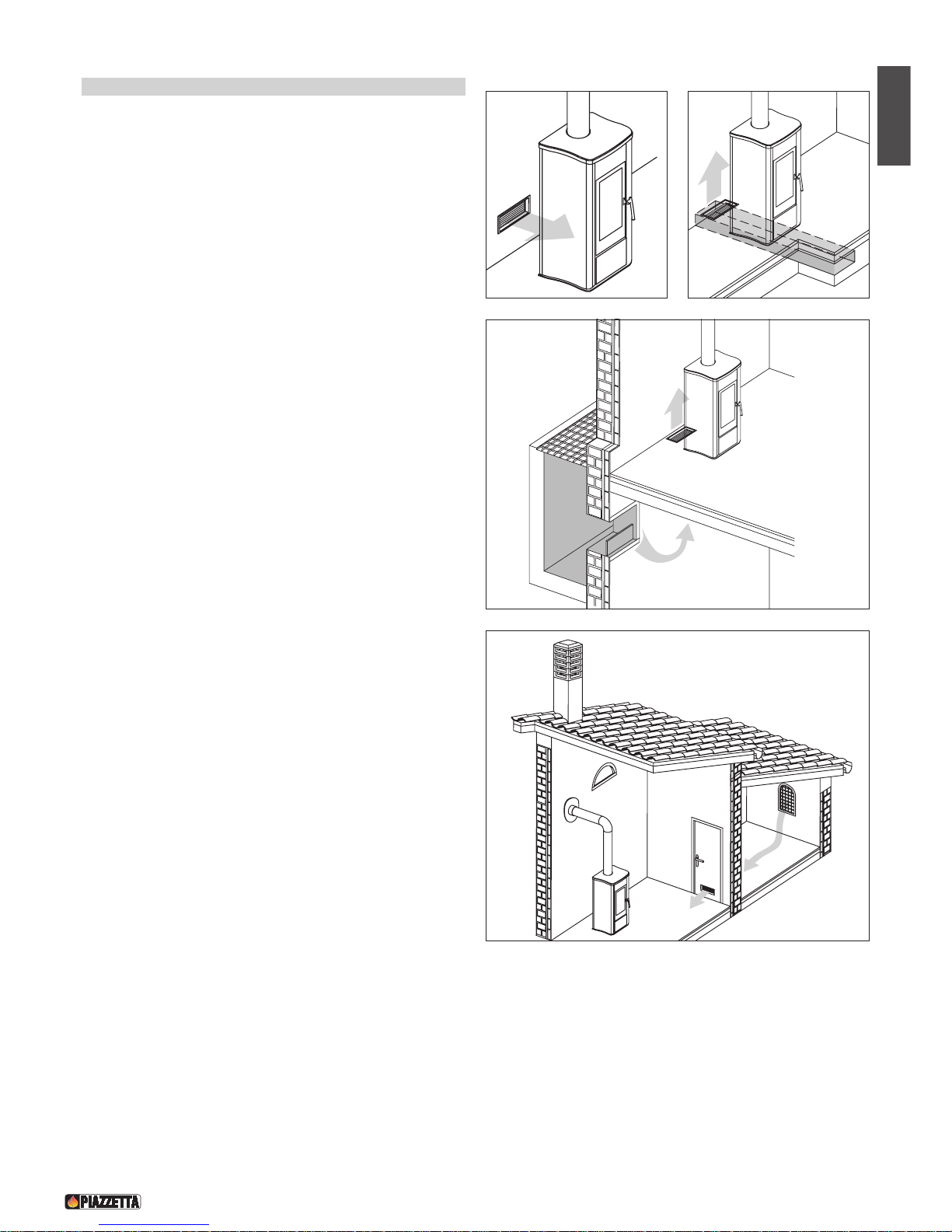
1.4 Presa d’aria esterna - Fig. 12÷15
La stufa deve disporre dell’aria necessaria per garantire il regolare
funzionamento della combustione.
- Assicurarsi che nel locale dove viene installato il focolare sia
installata una presa d’aria di dimensione pari o superiore al dato
riportato al paragrafo “Dati tecnici”.
- La presa d’aria esterna può essere protetta da una griglia di protezione
esterna purchè non si riduca la sezione minima della portata d’aria
indicata, ed essere posizionata in modo tale da non essere ostruita.
L’aria necessaria per il focolare si può ottenere nei differenti modi:
- tramite una griglia esterna diretta all’ambiente di installazione
(fig.12);
- con una canalizzazione tramite dei tubi diretti all’ambiente di
installazione, maggiorando la sezione minima libera indicata di
almeno il 15% (fig.13);
- attraverso un foro comunicante da un locale adiacente al luogo di
installazione, solo se tale flusso possa avvenire liberamente
dall’esterno da aperture fisse (fig.14);
- da un locale adiacente a quello di installazione solo se tale flusso
possa avvenire liberamente attraverso aperture comunicanti con
l’esterno (fig.15).
DT2030054-00
Fig. 12
DT2030194-00
Fig. 14
DT2030195-00
Fig. 15
DT2030193-00
Fig. 13
Page 8
8
Italiano
1.5 Ambiente di installazione
L’installazione dell’apparecchio deve avvenire in un luogo che ne consenta un sicuro e facile utilizzo ed una semplice manutenzione. Se il
prodotto che installate necessita di una presa di corrente elettrica tale luogo deve inoltre essere dotato di impianto elettrico con messa a
terra come richiesto dalle norme vigenti.
Il locale o i locali adiacenti rispetto a quello d’installazione dell’apparecchio devono rispettare le seguenti caratteristiche:
È vietata l’installazione dell’apparecchio nelle camere da letto, nei locali per bagno o doccia e nei locali dove ci sia un altro
apparecchio da riscaldamento sprovvisto di un proprio adeguato afflusso di aria (caminetto, stufa, ecc.).
Non essere adibiti ad autorimessa, magazzino di materiale combustibile né comunque ad attività con pericolo d’incendio.
Non essere messi in depressione rispetto all’ambiente esterno per effetto del tiraggio contrario provocato dalla presenza nel
locale di installazione del focolare di un altro apparecchio o di un dispositivo di aspirazione.
Non utilizzare nello stesso ambiente due stufe, un camino ed una stufa, una stufa e una cucina a legna, ecc... poiché il tiraggio
di uno potrebbe danneggiare il tiraggio dell’altro.
- solo nei locali ad uso cucina è possibile l’utilizzo di dispositivi adatti alla cottura dei cibi con relative cappe senza estrattore;
- sono ammesse apparecchiature a gas di tipo C (fare riferimento alle normative in vigore nel luogo di istallazione).
Non sono ammessi apparecchi a gas di tipo B (fare riferimento alle normative in vigore nel luogo di istallazione).
È vietato l’utilizzo della stufa o del caminetto contemporaneamente con condotti di ventilazione di tipo collettivo con o senza estrattore, altri
dispositivi, o altri apparecchi come: sistemi di aerazione forzata o altri sistemi di riscaldamento con l’utilizzo di ventilazione per il ricambio
dell’aria. Questi possono mettere in depressione l’ambiente di installazione, anche se installati in ambienti attigui e comunicanti con il locale
di installazione.
1.6 Portata del solaio
Verificare la capacità portante del solaio facendo riferimento al peso del prodotto nel paragrafo “Dati tecnici”.
Se il solaio non ha una idonea capacità portante si devono prendere adeguate contromisure, ad esempio utilizzando una piastra in lamiera
per distribuire il carico.
1.7 Capacità di riscaldamento
Verificare la capacità di riscaldamento dell’apparecchio confrontando la potenza nominale riportata al paragrafo “Dati tecnici” e la potenza
richiesta dagli ambienti da riscaldare.
Il calcolo approssimativo del fabbisogno energetico si ottiene moltiplicando i metri quadrati per l’altezza del soffitto, il risultato viene moltiplicato
per un coefficiente che dipende dal grado di isolamento del fabbricato, ovvero, da fattori interni e fattori esterni della abitazione:
a) Fattori interni: tipologia di serramenti, spessore degli isolamenti e delle pareti, tipologia di materiali costruttivi, presenza di vani scale,
pareti con ampie vetrate, soffitti elevati, ubicazione del volume da riscaldare rispetto ad altri volumi adiacenti riscaldati o non riscaldati,
b) Fattori esterni: esposizione ai punti cardinali, velocità del vento, latitudine, altitudine, temperatura media esterna,…
Esempio di calcolo approssimativo del fabbisogno energetico per riscaldare un determinato volume a 18/20° C:
Il coefficiente che normalmente viene usato si determina a seconda delle condizioni reali che di volta in volta si presentano.
- Da 0,04 a 0,05 kW per metro cubo in ambiente ben isolato.
-
Da 0,05 a 0,06 kW per metro cubo in ambiente scarsamente coibentato.
3 locali da 20mq X (H soffitto) 2,7m = 162 mc (volume)
Nell’ipotesi di un ambiente con un buon grado di isolamento si può optare per un valore medio (coefficiente) di 0,045 kW
162 (volume) X 0,045 (kW) = 7,3 kW necessari (6300 kcal/h)
Conversione 1kW = 860 kcal/h
Per una corretta verifica e calcolo sul fabbisogno degli ambienti da riscaldare affidarsi ad un termotecnico (vedi “Normative di
riferimento”).
I prodotti con il sistema Multifuoco a parità di potenza nominale possono distribuire in modo omogeneo il calore nei locali da
riscaldare.
Page 9
Italiano
9
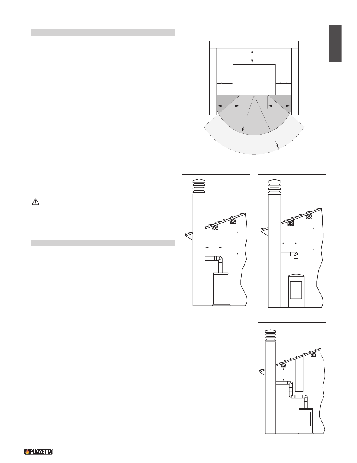
1.8 Distanze minime di sicurezza - Fig. 16
Prima di procedere con il montaggio scegliere la posizione dove
verrà installata la stufa.
Verificare le distanze minime di sicurezza da materiali sensibili
al calore o infiammabili, come da muri portanti e altre pareti, così
come anche da elementi in legno, mobilio, ecc.
Le distanze minime da rispettare sono:
A 20 cm dalla parete posteriore alla stufa
B 20 cm dalla parete laterale
C 100 cm nella zona radiante
Nel caso di pavimentazione sensibile al calore o infiammabile è
necessario usare una protezione in materiale isolante non
combustibile, per esempio: lastra in lamiera di acciaio, marmo,
piastrelle, ecc.
Le distanze minime da rispettare sono:
D 50 cm
E 30 cm
(misurato dallo spigolo interno dell’apertura del focolare)
Tenere qualsiasi prodotto infiammabile ben lontano dalla
stufa durante il suo funzionamento (minimo dalla zona
radiante) tipo: arredi in legno, tendaggi, tappeti, liquidi
infiammabili, ecc.
1.9 Collegamento alla canna fumaria - Fig. 17÷26
Per il collegamento del focolare al camino si possono usare al
massimo due curve, con cambio di direzione maggiore o uguale a
90°, e lunghezza del canale da fumo in proiezione orizzontale non
superiore a 2 m. Figure 17-18-19
I raccordi devono essere il più brevi possibili, privi di strozzature,
realizzati in materiali resistenti alla corrosione dei fumi e a
temperature di 550-600° C.
Per il collegamento alla canna fumaria, si consiglia di usare tubi e
curve del Gruppo Piazzetta S.p.A., in quanto lo scarico fumi del
prodotto è dimensionato per l‘innesto di questi, inoltre le curve
sono dotate d’ispezione che consentono il controllo, la pulizia, e la
manutenzione dell‘impianto.
Possono essere applicati anche altri tubi, previo adeguamento o
verifica della compatibilità del manicotto d‘inserimento tenendo
conto che i tubi e le curve devono essere costruiti nel rispetto delle
normative vigenti. In tale caso però il Gruppo Piazzetta S.p.A.
assicura il buon funzionamento solo per quanto è di sua
produzione ed impiegato secondo specifiche.
Se si dovesse realizzare un disassamento con delle curve si
consiglia di prestare attenzione, in quanto il collegamento eseguito
potrebbe non avere la capacità di reggere il peso soprastante, e
potrebbe richiedere dei sistemi di supporto adeguati.
Z
o
n
a
r
a
d
i
a
n
t
e
d
e
l
l
'
a
p
e
r
t
u
r
a
d
e
l
f
o
c
o
l
a
r
e
Parete posteriore
Protezione a pavimento
A
B
B
E
D
C
STUFA
Parete laterale
Parete laterale
E
DT2030059-00
Fig. 16
MAX 2M
MIN 40 cm
SÌ
DT2030056-00
Fig. 17
MAX 2M
MIN 40 cm
SÌ
DT2030196-00
Fig. 18
MIN 40 cm
NO
DT2030197-00
Fig. 19
Page 10
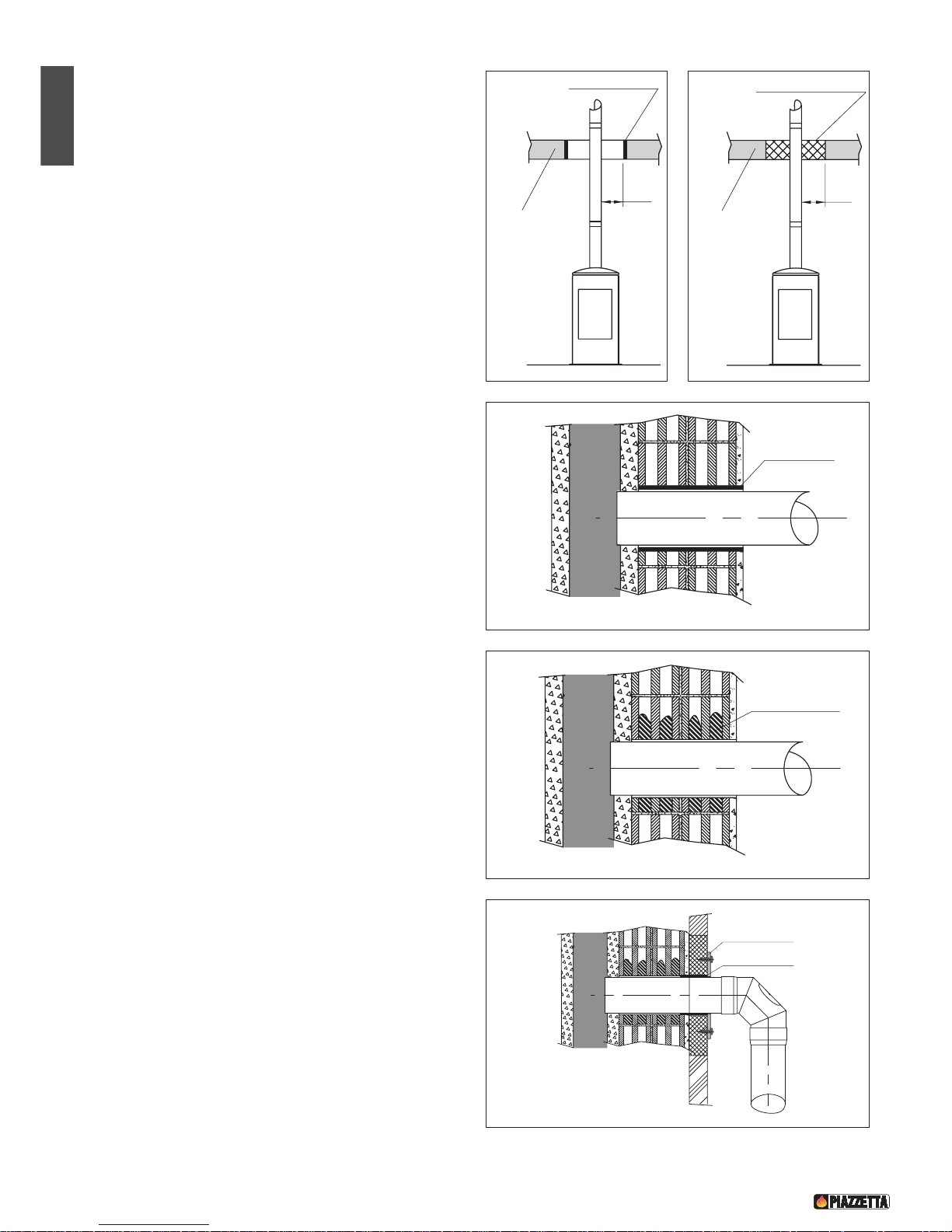
Il collegamento alla canna fumaria deve rispettare la distanza
minima di 40 cm da elementi di costruzione sensibili al calore o da
materiali infiammabili (rivestimento, travi o soffitti in legno, ecc,).
Vedi figure 17-18-19-25-26
Se il raccordo dovesse attraversare elementi o pareti in materiali
infiammabili sensibili al calore, o pareti portanti, creare:
- un isolamento pari o superiore a 20 cm attorno al raccordo (per
esempio malta cementizia calcestruzzo leggero; Figura 21-25-26
- oppure, il raccordo deve restare ad una distanza di sicurezza di
40 cm interponendo un tubo di materiale non infiammabile ed
indeformabile. Figura 20
Se il raccordo passa attraverso murature o pareti non infiammabili:
- le intercapedini devono essere riempite con materiali non
infiammabili, indeformabili e con ridotta capacità di trasmissione
del calore (per esempio calcestruzzo leggero); Figura 23
- oppure, le intercapedini possono essere protette con appositi tubi
di protezione. Figura 22
Controllare che il collegamento alla canna fumaria sia effettuato in
modo da garantire la tenuta ai fumi per le condizioni di
funzionamento dell’apparecchio in depressione.
Controllare che il tubo non entri troppo all’interno della canna
fumaria, creando una strozzatura al passaggio fumi. Figura 22-23.
10
Italiano
DIAFRAMMA
40 cm
MATERIALE
INFIAMMABILE
DT2030057-00
Fig. 20
20 cm
MATERIALE ISOLANTE
MATERIALE
INFIAMMABILE
DT2030199-00
Fig. 21
DIAFRAMMA
CANNA FUMARIA
DT2030202-00
Fig. 22
CANNA FUMARIA
MATERIALE DI
RIEMPIMENTO
DT2030203-00
Fig. 23
CANNA FUMARIA
ROSONE COPRIBORDO
RACCORDO A MURO
DT2030198-00
Fig. 24
Page 11
Italiano
11
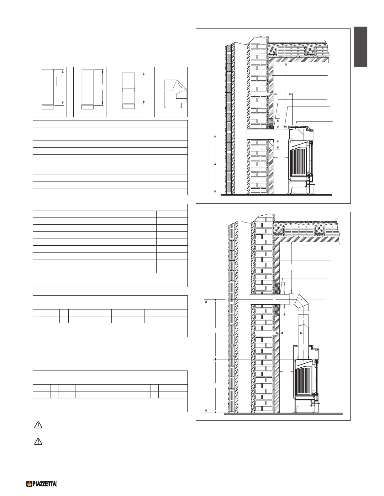
Scarico fumi POSTERIORE-SUPERIORE
NOZIONI IMPORTANTI:
- tubi con diametro 15 cm;
- ad ogni innesto vanno tolti 5 cm;
Determinato il foro di collegamento alla canna fumaria, fissare il
raccordo a muro e il rosone copribordo (fig. 24)
Accertarsi che il tutto sia installato a regola d’arte.
Le misure riportate nelle figure sono indicative in quanto è
previsto l’installazione del prodotto in un pavimento e una
parete ortogonale.
B
Rosone a m ur o
Pa re t e infi am ma bi le
o s en s i bi le al ca lo re
Ra cc or do sca ri co
fu mi po st er io re
op zi on al e
40 mi n.
20
20
20
CANNA FU MA RI A
E
Sp ez z one tu bo
DT2030738-00
Fig. 25
A
C
H
40 mi n.
Pa re te in fi am m abi le
o s ensib il e a l c al or e
Ro so ne a m ur o
Tu bi
20
20
20
CA NN A F UM AR IA
D
B
DT2030739-00
Fig. 26
TR100
95
DT2030060-00
T100
95
DT2030256-00
T50T50
90
DT2030201-00
24,5
24,5
C6
DT2030200-01
Calcolo indicativo del tratto di tubi verticale conoscendo “H”.
Esempio: H = 80 cm
80 - 24,5 + 5 = 60,5
H Raccordo C6 Innesto tubo Lunghezza tubo
Un tubo da 100 cm T100 va tagliato a 60,5 cm
Il tubo va tagliato dalla parte del maschio.
Calcolo indicativo del tratto di tubi orizzontale conoscendo “E”.
Esempio su stufa e917: E = 50 cm, D = 38 cm
50 + 38 - 24,5 + 5 = 68,5
E D Raccordo C6 Innesto tubo
Lunghezza tubo
Un tubo da 100 cm T100 va tagliato a 68,5 cm
Il tubo va tagliato dalla parte del maschio.
TABELLA SCARICO FUMI POSTERIORE (Misure in cm)
Modello Quota A Quota B
e911 non previsto non previsto
e912 102 29,5
e915 85 26,5
e917 93 30
e918 85 26,5
e920 102 29,5
e922 100,5 30
e923 102 29,5
Dimensione B calcolata con distanza di sicurezza di 20 cm dalla parete
TABELLA SCARICO FUMI SUPERIORE (Misure in cm)
Modello Quota C Quota D Quota H Quota F
e911 126,5 37,5 120 246,5
e912 93 37,5 120 213
e915 76,5 34,5 120 196,5
e917 83,5 38 120 203,5
e918 76,5 34,5 120 196,5
e920 93 37,5 120 213
e922 91,5 38 120 211,5
e923 93 37,5 120 213
Dimensione D calcolata con distanza di sicurezza di 20 cm dalla parete
Dimesione F e H calcolate con un tubo da un metro T100 ed una curva C6
Page 12

12
Italiano
1.10 Prevenzione degli incendi domestici
L’installazione e l’utilizzo del prodotto deve essere fatta in
conformità con le istruzioni del fabbricante, e nel rispetto delle
normative europee, nazionali e dei regolamenti locali.
Quando un tubo di scarico fumi passa attraverso ad una
parete o ad un soffitto è necessario applicare modalità di
installazioni particolari (protezione, isolamento termico,
distanze da materiali sensibili al calore, ecc...) Fare
riferimento al paragrafo “Collegamento alla canna
fumaria”.
- Si raccomanda inoltre di mantenere al di fuori della zona di
irraggiamento del focolare, e comunque alla distanza di almeno
1m dal blocco riscaldante tutti gli elementi di materiale
combustibile o infiammabile.
- Per altre nozioni fare riferimento al paragrafo “Distanze di
sicurezza” e “Collegamento alla canna fumaria”.
- Il condotto scarico fumi, comignolo, canna fumaria, presa d’aria
esterna, devono essere sempre liberi da ostruzioni, puliti e
controllati periodicamente almeno due volte durante il periodo
stagionale dall’avviamento del prodotto e durante il suo utilizzo.
Dopo un periodo di inattività dell’apparecchio è consigliato
verificare quanto citato sopra. Per ulteriori informazioni
consultare lo spazzacamino.
- Utilizzare solo combustibili consigliati (Vedi paragrafo
“Combustibili”).
Page 13
Italiano
13
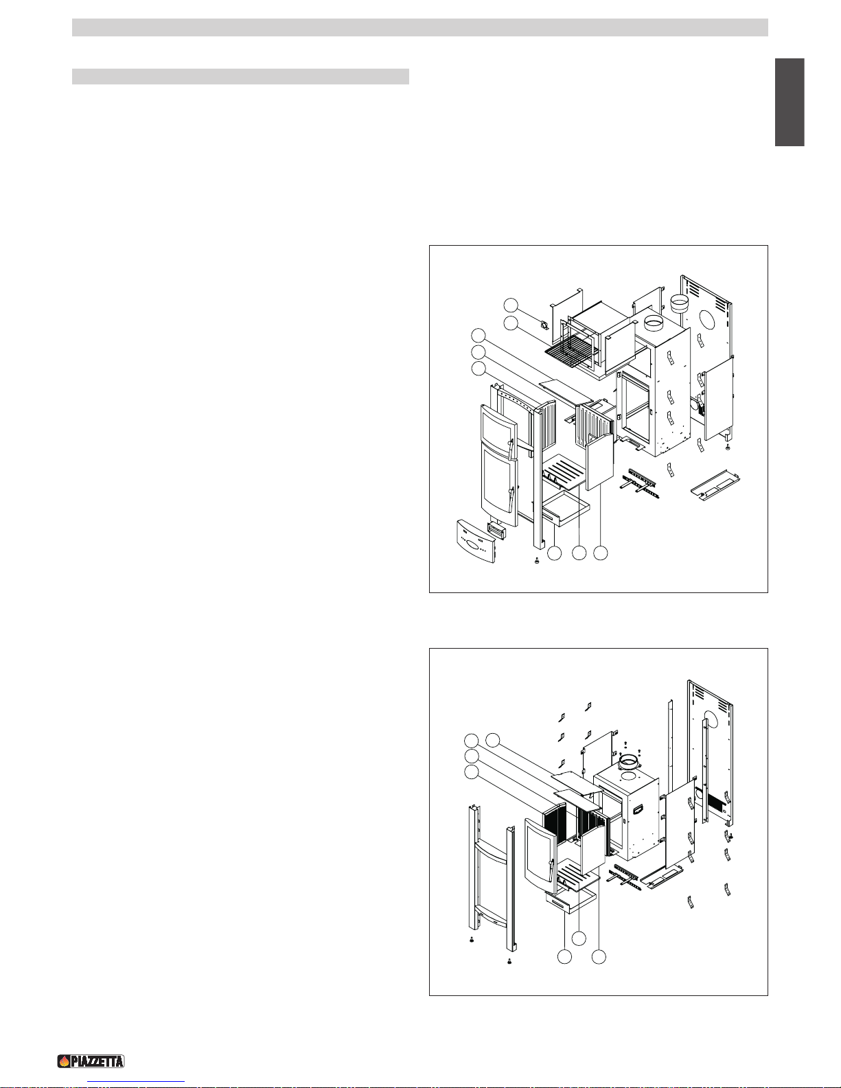
2.1 Descrizione dell’apparecchio
Le stufe Piazzetta, sempre all’avanguardia, in linea con i più severi requisiti in fatto di resa termica e tutela dell’ambiente, rappresentano
una soluzione per il riscaldamento davvero speciale per caratteristiche estetiche e funzionali.
Il rivestimento esterno realizzato in pregiata maiolica, accumula il calore generato dalle ampie superfici radianti dei monoblocchi, che viene
successivamente diffuso con gradualità e omogeneità nell’ambiente.
La stufa in maiolica, oltre ad un indubbio valore estetico, non compromette la qualità dell’aria che conserva un giusto grado di umidità.
Le temperature non troppo elevate aumentano la sicurezza di utilizzo e danno la sensazione di un piacevole e diffuso tepore.
2.0 CARATTERISTICHE E DATI TECNICI
DT2010446-02
No Descrizione . . . . . . . . . . . . . . . . . . . . . . . . . . . .Q.tà
1 Laterale Sx Aluker 282x430 e920 . . . . . . . . . . . . . . . . .1
2 Schienale Aluker 415x410 e920 . . . . . . . . . . . . . . . . . .1
3 Laterale Dx Aluker 282x430 e920 . . . . . . . . . . . . . . . . .1
4 Piano fuoco e920 . . . . . . . . . . . . . . . . . . . . . . . . . . . . .1
5 Cassetto cenere e920 . . . . . . . . . . . . . . . . . . . . . . . . . .1
6 Deflettore fumi inferiore e920 . . . . . . . . . . . . . . . . . . . .1
7 Griglia cottura e911 . . . . . . . . . . . . . . . . . . . . . . . . . . . .1
8 Termometro forno . . . . . . . . . . . . . . . . . . . . . . . . . . . . .1
No Descrizione . . . . . . . . . . . . . . . . . . . . . . . . . . . .Q.tà
1 Laterale Sx Aluker 282x430 e920 . . . . . . . . . . . . . . . . .1
2 Schienale Aluker 415x410 e920 . . . . . . . . . . . . . . . . . .1
3 Laterale Dx Aluker 282x430 e920 . . . . . . . . . . . . . . . . .1
4 Piano fuoco e920 . . . . . . . . . . . . . . . . . . . . . . . . . . . . .1
5 Cassetto cenere e920 . . . . . . . . . . . . . . . . . . . . . . . . . .1
6 Deflettore fumi inferiore e920 . . . . . . . . . . . . . . . . . . . .1
7 Deflettore fumi superiore e920 . . . . . . . . . . . . . . . . . . .1
5
5
4
3
6
2
1
7
8
DT2030756-00
7
6
2
1
5
4
3
DT2030757-00
e911
e912
Page 14
14
Italiano
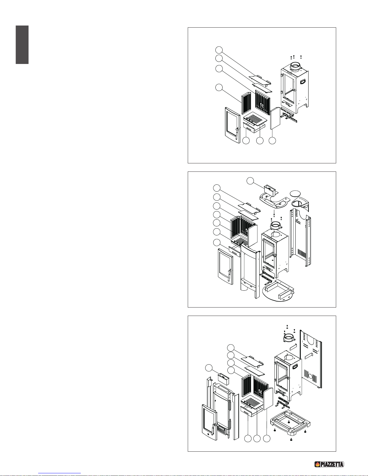
No Descrizione . . . . . . . . . . . . . . . . . . . . . . . . . . . .Q.tà
1 Laterale Sx Aluker 200x380 e915 . . . . . . . . . . . . . . . . .1
2 Schienale Aluker 335x355 e915 . . . . . . . . . . . . . . . . . .1
3 Laterale Dx Aluker 200x380 e915 . . . . . . . . . . . . . . . . .1
4 Piano fuoco e915 . . . . . . . . . . . . . . . . . . . . . . . . . . . . .1
5 Cassetto cenere e915 . . . . . . . . . . . . . . . . . . . . . . . . . .1
6 Deflettore fumi inferiore e915 . . . . . . . . . . . . . . . . . . . .1
7 Deflettore fumi superiore e915 . . . . . . . . . . . . . . . . . . .1
No Descrizione . . . . . . . . . . . . . . . . . . . . . . . . . . . .Q.tà
1 Laterale Sx Aluker 200x380 e915 . . . . . . . . . . . . . . . . .1
2 Schienale Aluker 335x355 e915 . . . . . . . . . . . . . . . . . .1
3 Laterale Dx Aluker 200x380 e915 . . . . . . . . . . . . . . . . .1
4 Piano fuoco e915 . . . . . . . . . . . . . . . . . . . . . . . . . . . . .1
5 Cassetto cenere e915 . . . . . . . . . . . . . . . . . . . . . . . . . .1
6 Deflettore fumi inferiore e915 . . . . . . . . . . . . . . . . . . . .1
7 Deflettore fumi superiore e915 . . . . . . . . . . . . . . . . . . .1
8 Serbatoio umidificatore e917 . . . . . . . . . . . . . . . . . . . .1
No Descrizione . . . . . . . . . . . . . . . . . . . . . . . . . . . .Q.tà
1 Laterale Sx Aluker 200x380 e915 . . . . . . . . . . . . . . . . .1
2 Schienale Aluker 335x355 e915 . . . . . . . . . . . . . . . . . .1
3 Laterale Dx Aluker 200x380 e915 . . . . . . . . . . . . . . . . .1
4 Piano fuoco e915 . . . . . . . . . . . . . . . . . . . . . . . . . . . . .1
5 Cassetto cenere e915 . . . . . . . . . . . . . . . . . . . . . . . . . .1
6 Deflettore fumi inferiore e915 . . . . . . . . . . . . . . . . . . . .1
7 Deflettore fumi superiore e915 . . . . . . . . . . . . . . . . . . .1
8 Serbatoio umidificatore e917 . . . . . . . . . . . . . . . . . . . .1
5
34
1
7
6
2
DT2030758-00
e915
6
5
4
7
8
3
2
1
DT2030761-00
e917
34
5
2
6
7
8
1
DT2030762-00
e918
Page 15
Italiano
15
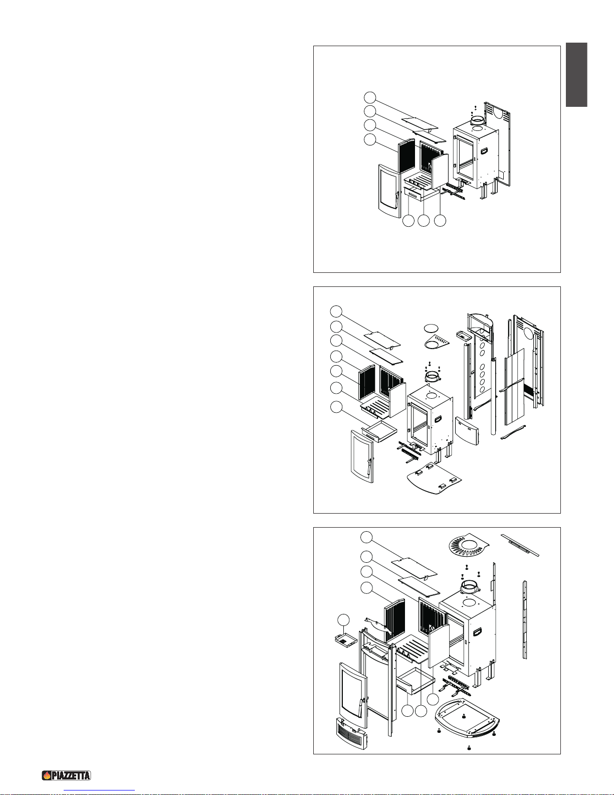
No Descrizione . . . . . . . . . . . . . . . . . . . . . . . . . . . .Q.tà
1 Laterale Sx Aluker 282x430 e920 . . . . . . . . . . . . . . . . .1
2 Schienale Aluker 415x410 e920 . . . . . . . . . . . . . . . . . .1
3 Laterale Dx Aluker 282x430 e920 . . . . . . . . . . . . . . . . .1
4 Piano fuoco e920 . . . . . . . . . . . . . . . . . . . . . . . . . . . . .1
5 Cassetto cenere e920 . . . . . . . . . . . . . . . . . . . . . . . . . .1
6 Deflettore fumi inferiore e920 . . . . . . . . . . . . . . . . . . . .1
7 Deflettore fumi superiore e920 . . . . . . . . . . . . . . . . . . .1
No Descrizione . . . . . . . . . . . . . . . . . . . . . . . . . . . .Q.tà
1 Laterale Sx Aluker 282x430 e920 . . . . . . . . . . . . . . . . .1
2 Schienale Aluker 415x410 e920 . . . . . . . . . . . . . . . . . .1
3 Laterale Dx Aluker 282x430 e920 . . . . . . . . . . . . . . . . .1
4 Piano fuoco e920 . . . . . . . . . . . . . . . . . . . . . . . . . . . . .1
5 Cassetto cenere e920 . . . . . . . . . . . . . . . . . . . . . . . . . .1
6 Deflettore fumi inferiore e920 . . . . . . . . . . . . . . . . . . . .1
7 Deflettore fumi superiore e920 . . . . . . . . . . . . . . . . . . .1
8 Serbatoio umidificatore e922 . . . . . . . . . . . . . . . . . . . .1
No Descrizione . . . . . . . . . . . . . . . . . . . . . . . . . . . .Q.tà
1 Laterale Sx Aluker 282x430 e920 . . . . . . . . . . . . . . . . .1
2 Schienale Aluker 415x410 e920 . . . . . . . . . . . . . . . . . .1
3 Laterale Dx Aluker 282x430 e920 . . . . . . . . . . . . . . . . .1
4 Piano fuoco e920 . . . . . . . . . . . . . . . . . . . . . . . . . . . . .1
5 Cassetto cenere e920 . . . . . . . . . . . . . . . . . . . . . . . . . .1
6 Deflettore fumi inferiore e920 . . . . . . . . . . . . . . . . . . . .1
7 Deflettore fumi superiore e920 . . . . . . . . . . . . . . . . . . .1
8 Serbatoio umidificatore P960 . . . . . . . . . . . . . . . . . . . .1
7
6
2
1
5 4 3
DT2030759-00
e920
5
4
3
1
2
6
7
DT2030760-00
e922
6
2
1
7
3
4
5
8
DT2030772-00
e923
Page 16
16
Italiano
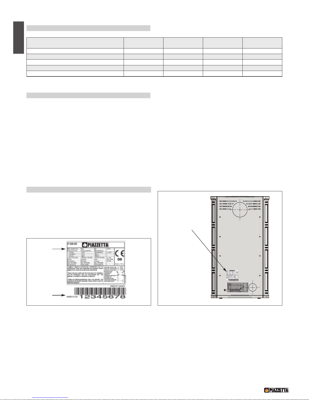
2.4 Dati di identificazione del prodotto - Fig. 28-29
La targhetta tecnica riporta i dati e le prestazioni dell’apparecchio.
La manomissione, l’asportazione, la mancanza della Targhetta
Tecnica, rende difficoltosa qualsiasi operazione di installazione e
manutenzione, dalla mancanza di identificazione del prodotto.
In caso di danneggiamento richiederne un duplicato la centro
assistenza Piazzetta.
DT2030778-01
TARGHETTA TECNICA
DI IDENTIFICAZIONE
PRODOTTO
Fig. 29
Nome prodotto
Numero matricola
DT2030070-01
Fig. 28
Descrizione e911 e912
e915
e917 - e918
e920
e922 - e923
Guanto destro In dotazione In dotazione In dotazione In dotazione
Bomboletta vernice spray siliconica In dotazione In dotazione In dotazione In dotazione
Tubi e curve per collegamento canna fumaria Accessorio Accessorio Accessorio Accessorio
Raccordo scarico posteriore D.150 - Accessorio Accessorio Accessorio
Kit ventilazione Multifuoco System 2003 Accessorio Accessorio - Accessorio
2.2 Accessori
2.3 Caratteristiche
Combustibile . . . . . . . . . . . . . . . . . . . . . . . . . . . . . . . . . . . . . . . . . . legna
Monoblocco . . . . . . . . . . . . . . . . . . . . . . . . . . . . . . . . . . . . . . . . . . acciaio verniciato
Focolare. . . . . . . . . . . . . . . . . . . . . . . . . . . . . . . . . . . . . . . . . . . . . . Aluker
®
Piano fuoco con paralegna . . . . . . . . . . . . . . . . . . . . . . . . . . . . . . . in ghisa
Registro aria primaria . . . . . . . . . . . . . . . . . . . . . . . . . . . . . . . . . . . regolabile
Registro aria secondaria . . . . . . . . . . . . . . . . . . . . . . . . . . . . . . . . . regolabile
Cassetto cenere. . . . . . . . . . . . . . . . . . . . . . . . . . . . . . . . . . . . . . . . estraibile
Vetro ceramico resistente a 750°C . . . . . . . . . . . . . . . . . . . . . . . . . -
Maniglia. . . . . . . . . . . . . . . . . . . . . . . . . . . . . . . . . . . . . . . . . . . . . . in acciaio con impugnatura in materiale siliconico
Forno . . . . . . . . . . . . . . . . . . . . . . . . . . . . . . . . . . . . . . . . . . . . . . . in acciaio inox (solo per stufa e911)
Scarico fumi . . . . . . . . . . . . . . . . . . . . . . . . . . . . . . . . . . . . . . . . . . superiore o posteriore (nella stufa e911 solo scarico superiore)
Page 17
Italiano
17
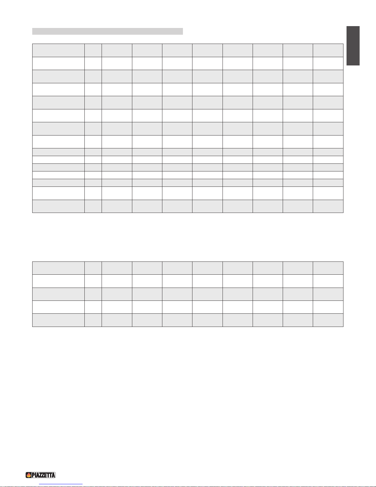
2.5 Dati tecnici
Questi dati sono ottenuti utilizzando legna di faggio con umidità inferiore al 20% ad intervalli per ogni singola ricarica di circa un’ora.
Apparecchio ad uso intermittente.
Dati tecnici a focolare chiuso per il calcolo della canna fumaria
Unità
di misura
e911 e912 e915 e917 e918 e920 e922 e923
Potenza termica nominale
kW 7 8 5 5 5 8 8 8
Consumo alla potenza
termica nominale
kg/h 2,1 2,6 1,7 1,7 1,7 2,6 2,6 2,6
Rendimento termico
% 80,2 75,5 82,5 82,5 82,5 75,5 75,5 75,5
Contenuto CO (al 13% O2) % 0,11 0,10 0,11 0,11 0,11 0,10 0,10 0,10
Omologato secondo
norma
- EN 13240 EN 13240 EN 13240 EN 13240 EN 13240 EN 13240 EN 13240 EN 13240
N° rapporto omologa CE
- CS-06-146 CS-06-145 CS-06-144 CS-06-144 CS-06-144 CS-06-145 CS-06-145 CS-06-145
Nº registrazione VKF AEAI
- - - Z 13000 - - Z 13000 - -
Diametro scarico
cm Ø15 Ø15 Ø15 Ø15 Ø15 Ø15 Ø15 Ø15
Apertura focolare
cm 29x40 29x40 25x35 25x35 25x35 29x40 29x40 29x40
Dimensione forno (LxPxH)
cm 31x34 h26,5 - - - - - - -
Superficie focolare
cm
2
1130 1130 875 875 875 1130 1130 1130
Peso stufa
kg ca. - - - - - - - -
Peso stufa con
rivestimento
kg ca. 230 190 136 151 146 163 181 183
Presa d’aria esterna
a sezione utile minima
cm
2
100 100 100 100 100 100 100 100
Unità
di misura
e911 e912 e915 e917 e918 e920 e922 e923
Potenza termica
nominale
kW 7 8 5 5 5 8 8 8
Portata fumi g/s 6 9 4 4 4 9 9 9
Temp. media dei fumi
nel tubo di scarico
°C 260 340 300 300 300 340 340 300
Tiraggio minimo Pa 10 12 10 10 10 12 12 12
Page 18
18
Italiano
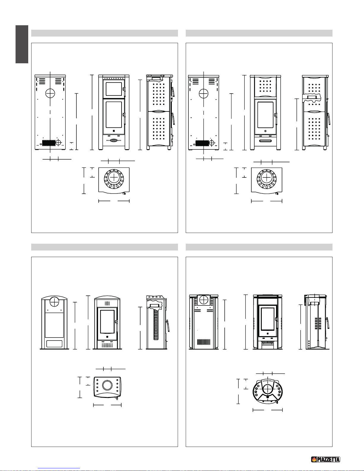
2.6 Dimensioni e911 2.7 Dimensioni e912
13 5
126,5
102
47
55
13
Ø15
14,5
17,5
102
47
55
13
Ø15
93
135
14,5
17 ,5
DT1020017-00DT1020016-00
Ø
14 ,5
50
96
76 ,5
15
37
85
DT1020095-00
46
55
10 2
92 ,5
19
84 ,2
Ø15
DT1020232-00
2.8 Dimensioni e915 2.9 Dimensioni e917
Page 19
Italiano
19
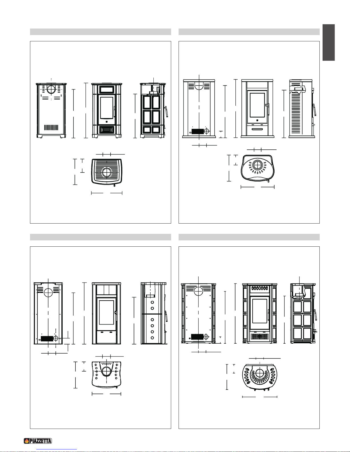
2.10 Dimensioni e918 2.11 Dimensioni e920
26
10 7
60
50
95
Ø1 5
86
Ø
11 3,5
93
10 2
65
15
19,5
13
51
14 ,5
DT1020015-00DT1020270-00
56
18 ,5
12 0
100, 5
11,5
14,5
91, 5
51
Ø15
DT1020231-00
10 2
117
17
49
68
93
Ø15
14, 5
13
DT1020271-00
2.12 Dimensioni e922 2.13 Dimensioni e923
Page 20
20
Italiano
3.0 USO
DT2010453-00
3.1 Combustibile - Fig. 30
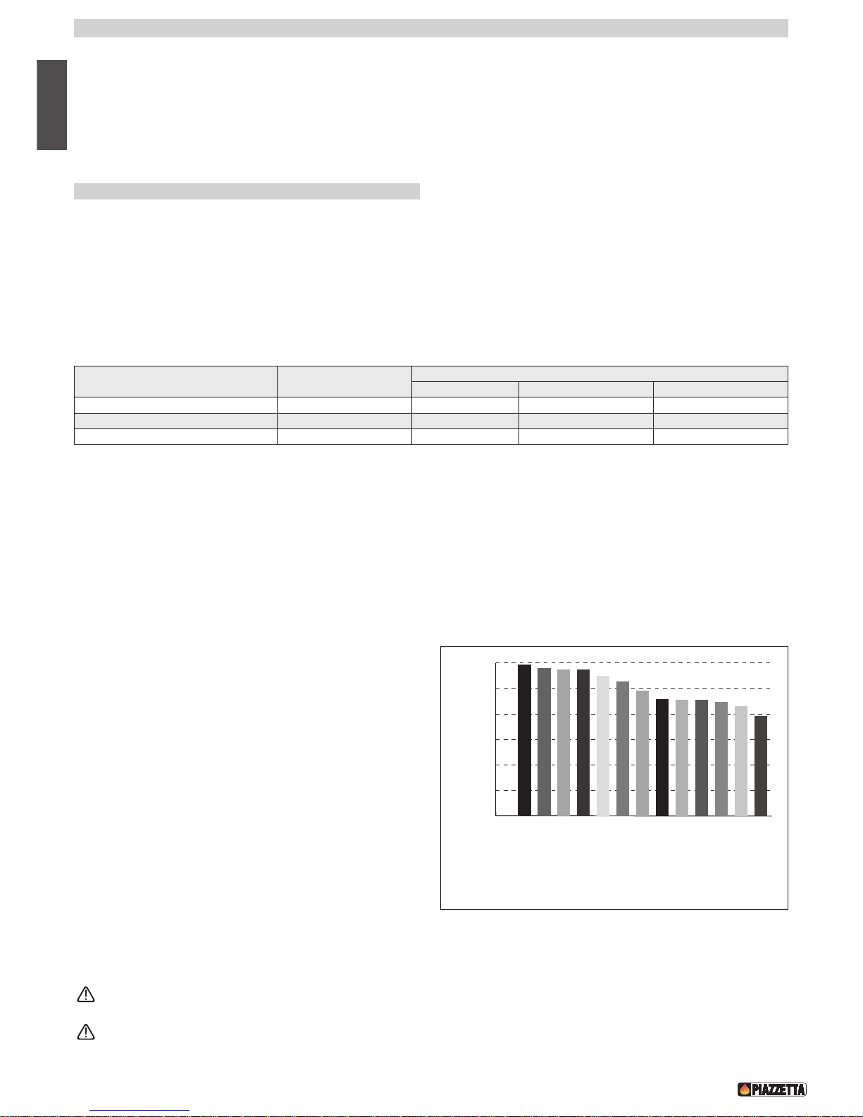
Usare legna ben stagionata e secca, inferiore al 20% di umidità.
Per ottenere legna pronta da ardere è necessario che questa venga asciugata all'aperto ed al riparo dalle precipitazioni atmosferiche
perlomeno 2 anni dopo il taglio.
Più bassa è la quantità di umidità relativa del legno e più alto è il potere calorifico, la legna appena tagliata possiede un potere energetico
inferiore del 50% rispetto a quella secca.
Bruciando legna troppo umida si sprecano gran parte delle calorie per l'evaporazione dell'acqua in essa contenuta e soprattutto si
incrostano notevolmente le pareti della camera di combustione e del condotto di evacuazione fumi, compromettendone la buona resa.
Quindi come si vede dalla tabella sottostante all’aumentare dell’umidità diminuisce il potere calorifico.
* Valori indicativi.
E' buona norma acquistare la legna durante il periodo estivo (giugno-luglio), in quanto i tagli dei boschi si eseguono prevalentemente in
autunno, quindi siamo sicuri che è stagionata già da circa 1 anno.
Possiamo classificare il legno da ardere in due qualità: "buone" e "mediocri o cattive". La suddivisione è dovuta alla resa termica della legna,
dal maggior tempo di fiamma che esercita, dalla sua composizione e dalla consistenza.
Combustibili di classe buona
- Possono essere consigliati i legnami della famiglia delle latifoglie forti: faggio, carpino, quercia, robinia, frassino, betulla, acero,
olmo.
- Sono maggiormente indicati come legno da ardere tutti i legnami
poco resinosi e di tipo consistente, rappresentando un legno duro e
pesante, fornendo al focolare una fiamma sostenuta e persistente.
Combustibili di classe mediocre o cattiva
- Possono essere sconsigliati i legnami della famiglia delle conifere, il
salice, il pioppo, ontano. Questi legnami hanno la caratteristica di
essere resinosi, creando: più fuliggine, poca brace, scoppiettii, richiesta
di una pulizia più frequente alla canna fumaria e all’apparecchio.
-
Un’altra caratteristica di questi legnami è che sono rappresentati da un legno
tenero e leggero, che fornisce al focolare una fiamma si vivace ma di breve
durata, che comporta un consumo di legna superiore a parità di potenza.
Combustibili non idonei
- Non usare mai legno umido o legno con pece.
- Non possono essere usati: scarti (immondizie), la carta straccia; le bricchette di carta; il legno compensato o truciolato; i pannelli fibrosi;
gli imballaggi; legno verniciato o legni impellicciati con materiale sintetico, laminati plastici, cartone, cartoni di latte.
È vietato utilizzare combustibile liquido di qualsiasi genere.
Tutti questi materiali o loro simili possono essere: pericolosi per l’utente, danneggiare il focolare, il raccordo scarico fumi, la
canna fumaria e non come ultimo inquinare la natura.
• Alcune importanti nozioni possono essere determinanti per la
buona resa di funzionamento del vostro prodotto, di seguito
citiamo alcune nozioni in merito per utilizzarlo al meglio cercando
di esservi di aiuto sulla scelta della legna da ardere, sulla
regolazione dei registri, e per una regolare utilizzo dell’apparecchio.
• Durante il funzionamento, alcune parti della stufa (porta, maniglia,
registri, pezzi in ceramica) possono raggiungere temperature elevate.
Fate dunque molta attenzione ed usate le dovute precauzioni.
• Quando dovete ricaricare il focolare di legna o regolare l'afflusso
d'aria, usate il guanto in dotazione.
DT2010055-00
Percentuale di umidità (W) Tempo di stagionatura
POTERE CALORIFICO DELLA LEGNA (Faggio)*
kWh/kg kcal/kg kWh/dm
3
20 dopo 2 anni 4 3400 2.9
30 dopo 1 anno 3.4 2900 2.8
40 dopo 6 mesi 2.8 2410 2.7
0
0,5
1,0
1,5
2,0
2,5
3,0
Pot ere c alori fi co (K W h/d m
3
w= 20%)
ABETE ROSSO
ABETE BIANCO
SALICE
ONTANO
PIOPPO
PINO
LARICE
BETULLA
FAGGIO
FRASSINO
QUERCIA
ROBINIA
F
AGGIO BIANCO
Valori indicativi riferiti ad UN decimetro cubo di legna di forma omogenea con
una percentuale di umidità (w) di circa 20%.
DT2010053-00
Page 21
Italiano
21
Pezzatura della legna
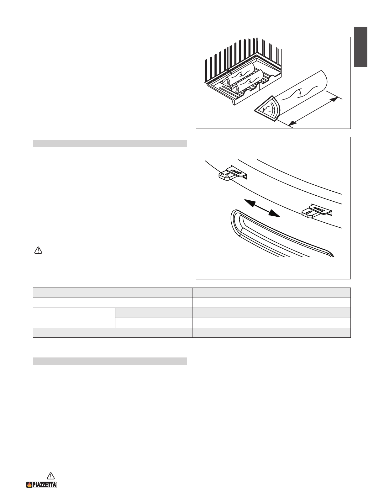
Anche le dimensioni della legna possono influire sulla buona resa del
prodotto:
- È fondamentale che la legna sia disposta sul braciere, sopra uno
strato di braci.
- La pezzatura della legna non deve andare a ridosso dell’aluker o del
vetro e non deve essere disposta a catasta. Quindi posizionare la
legna come raffigurato nella figura 30;
- Consigliamo quindi di utilizzare legna di dimensioni:
perimetro 30/35 cm circa;
lunghezza 20 - 25 - 30 cm circa in base alla tipologia del focolare.
3.2 Regolazione aria comburente - Fig. 31
Con i registri aria si determina la resa termica nominale, fate
attenzione alle posizioni riportate nella tabella seguente a seconda
dei combustibili usati.
Le posizioni sotto indicate si riferiscono naturalmente alla resa
nominale. Poiché la resa dipende anche dalle condizioni
atmosferiche, climatiche, e quindi dal tiraggio, l'esperienza vi
insegnerà a scegliere la posizione più idonea.
La regolazione si effettua come indicato nella figura a lato.
Nel caso si desideri una potenza minore, scegliere una posizione
inferiore a quella data, cioè spingere ulteriormente i registri verso la
posizione di minimo.
L’aumento eccessivo di combustibile ed eccessiva
apertura dei registri di aria rispetto a quanto riportato nella
tabella, provoca un aumento di calore dell’apparecchio,
diminuzione del rendimento, aumento di consumo di legna.
(*) Dati rilevati in laboratorio abilitato alla certificazione.
3.3 Prima accensione
Nella prima accensione dell’apparecchio sono necessarie due importanti fasi: la prova di funzionamento e l’avviamento del prodotto.
1. Prova di funzionamento
- Prima di fare la prova di funzionamento verificare che tutto sia installato in modo corretto (vedi norme generali).
- Iniziare con la fase di accensione (vedi paragrafo ACCENSIONE).
- La prima carica nominale va ridotta del 50%.
In caso di perdite di fumo:
• non aprire la porta del focolare;
• chiudere i registri aria comburente (posizione MINIMO);
• lasciare che il fuoco si spenga lentamente;
• aerare il locale prima di soggiornarvi;
• verificare la causa del mal funzionamento.
Non spegnere il fuoco con acqua, potreste danneggiare il focolare.
Peri metro
L
u
n
ghez
z
a
DT2030063-00
Fig. 30
MIN
MAX
DT2030755-00
Fig. 31
Aria secondaria
Aria primaria
Regolazione e quantità di materiale da bruciare per potenza nominale e911 e915-e917-e918 e912-e920-e922-e923
Materiale da bruciare Legna
Posizione registri
Primaria aria primaria chiuso aria primaria chiuso aria primaria 1/2 aperto
Secondaria
aria secondaria 1/2 aperto
aria secondaria aperto aria secondaria aperto
Quantità massima di combustibile da bruciare kg 2,10 kg 1,70 kg 2,60
Page 22
22
Italiano
2. Avviamento del prodotto
- Nel primo periodo di funzionamento è consigliato utilizzare il prodotto al minimo della capacità, caricando il focolare almeno per il primo
giorno al 50% in meno di legna rispetto alla carica nominale indicata.
- Mantenere i registri aria nella posizione di funzionamento (escluso accensione), vedi paragrafo “Regolazione dell’aria comburente”
- Questa fase permette un assestamento di tutti i componenti, e l’esalazione delle vernici, grassi, o liquidi oleosi serviti alla fabbricazione.
- In questo stadio iniziale lasciare arieggiato il locale.
- Questa procedura è da effettuarsi con il sistema di ventilazione forzato disinserito.
In seguito a questa procedura, l’apparecchio non emetterà più gli odori derivati dall'esalazione della vernice e dovrà essere alimentato solo ed
esclusivamente con le cariche nominali indicate.
3.4 Accensione - Fig. 32 - 33
Prima dell’accensione, togliere gli accessori in dotazione (bomboletta di vernice spray, guanto, ecc.) o elementi infiammabili
dal piano fuoco o dal cassetto cenere tranne la legna sul piano fuoco.
Nella fase di accensione il focolare dovrà essere portato velocemente alla temperatura di esercizio. Qualora questo avvenisse lentamente,
sarà inevitabile la formazione di condense che causano l’annerimento del focolare e del vetro.
Caricare il focolare con le quantità di combustibile e con le modalità come riportato di seguito:
1. Posizionare i registri dell’aria nella posizione aperta (MASSIMO)
(vedi paragrafo “Regolazione dell’aria comburente”).
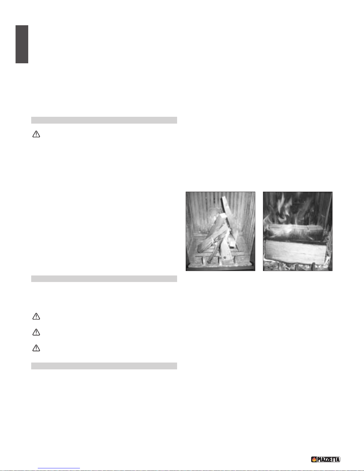
2. Porre al centro del focolare del combustibile adatto all’accensione
(carta, accendifuoco , etc.) unire in forma di piramide piccoli pezzi
di legna tenera (abete) fig.32. Per una rapida accensione della
legna tenere aperta l’anta circa due centimetri per 5-10 minuti.
3. Una volta che si è formato un letto di braci, procedere con le
cariche del combustibile fig. 33 e con le regolazioni dei registri,
facendo riferimento alla tabella del paragrafo “Regolazione aria
comburente”. Non aprire il focolare durante il funzionamento.
3.5 Apertura della porta
Durante il funzionamento la porta va aperta quando sul piano fuoco ci sono solo le braci. Aprire la porta quando le fiamme sono vive o
intense è rischioso sia per l’utente che per l’abitazione.
L'apertura della porta va fatta lentamente, tenendola per qualche secondo leggermente scostata prima della completa apertura.
Usare sempre il guanto in dotazione.
La porta è autochiudente, non chiuderla con violenza, il vetro potrebbe rompersi.
Il guanto non è fatto per poter prendere in mano le braci !!!
3.6 Funzionamento notturno al minimo
La stufa dopo il funzionamento normale durante il giorno, può prolungare il suo funzionamento per alcune ore durante la notte.
Alla sera durante l’ultima carica assicurarsi che il letto di braci sia sufficiente, caricare di legna il focolare, quindi portare i registri dell’aria
comburente al minimo. Il funzionamento notturno al minimo della stufa dipenderà dal tipo di legno (è consigliato usare un legno forte),
dal tiraggio della canna fumaria e dalle condizioni meteorologiche.
La vostra esperienza vi indicherà la quantità di legna da caricare e la regolazione necessaria dell’afflusso dell’aria comburente (vedi
il paragrafo “Regolazione aria comburente”).
Il mattino successivo riavviate la stufa al massimo per bruciare l’eventuale creosoto formatosi durante la notte. I depositi di creosoto
cominciano a formarsi quando la temperatura della canna fumaria scende sotto i 150 °C. Per evitarli, si deve cercare di mantenere il
focolare dell’apparecchio alla sua andatura normale (fase di resa termica nominale) più a lungo possibile.
Un funzionamento prolungato della stufa al minimo può richiedere una pulizia più frequente del focolare e della canna fumaria.
DT2030065-00
Fig. 33
DT2030064-00
Fig. 32
Page 23
Italiano
23
3.7 Funzionamento in condizioni atmosferiche avverse
Durante le stagioni intermedie con condizioni atmosferiche sfavorevoli, o quando le temperature esterne sono più alte, le variazioni
climatiche possono provocare un malfunzionamento del tiraggio impedendo un corretto deflusso dei fumi. In tal caso il focolare dovrà
essere caricato con poca legna, il registro dell’aria primaria aperto completamente in modo che la legna presente sul focolare arda più
velocemente, stabilizzando così il tiraggio.
3.8 Surriscaldamento e spegnimento
In caso di surriscaldamento, arrossamenti di alcune parti dell'apparecchio o del tubo di uscita fumi:
- interrompere immediatamente l'alimentazione;
- non aprire la porta del focolare;
- chiudere i registri aria (posizione MINIMA).
Il fuoco si spegnerà per insufficienza di aria.
Quando l’apparecchio è raffreddato controllare l’origine del problema e se necessario chiamare il personale specializzato.
In caso di incendio spegnere il fuoco mediate estintore.
È vietato spegnere il fuoco con acqua.
A causa di perdite fumi, aerare il locale prima di soggiornarvi.
3.9 Umidificatore (solo per stufa e917 – e918 – e922 – e923)
È possibile umidificare l’ambiente dove è installata la stufa. Utilizzando il “flacone spruzzatore 500cc” inserire l’acqua nel serbatoio
attraverso il foro sul piano cottura. Fare attenzione a non riempire oltre al limite posto sul serbatoio, indicato con il simbolo di “MAX”.
3.10 Uso del forno (solo per stufa e911)
Per la cottura dei cibi non Vi viene fornito un manuale, in quanto solo l’ esperienza può farvi da maestra ed unita alla fantasia e alle capacità personali,
vi permetterà di creare ottimi piatti. Di aiuto sono senza dubbio il termometro in dotazione che vi indica il momento giusto per introdurre i cibi e,
l’ampio sportello in vetro ceramico che consente di seguire in ogni momento la cottura.
Tuttavia alcuni suggerimenti vi saranno sicuramente utili:
- portate inizialmente il prodotto in temperatura, iniziando con cariche di legna di piccola pezzatura e solo successivamente introducete ceppi più
grandi e comunque non superiori alla carica nominale;
- il cibo non va introdotto appena viene raggiunta la temperatura desiderata, in quanto con molta probabilità, i gradi continueranno a salire rischiando
di rovinare il cibo introdotto nel forno;
- ad un certo punto la temperatura inizierà a scendere, quando si sarà stabilizzata per qualche minuto sarà il momento migliore per introdurre il cibo;
- si consiglia di non superare la temperatura di 250°C in quanto tale limite è più che sufficiente per ogni tipo di cottura. Solo nella fase iniziale è
consentito arrivare fino ad una punta massima di 280-300°C. Le temperature superiori, oltre che essere inadatte per una corretta cottura,
possono sottoporre le strutture a dilatazioni eccessive;
- una volta introdotto il cibo sarà sufficiente mantenere la temperatura costante con una calibrata aggiunta di legna ed una idonea regolazione dei
registri aria. Solamente l’esperienza vi potrà indicare quali saranno le condizioni migliori per la cottura di un cibo, la quantità di legna da bruciare in
un certo tempo e la posizione dei registri, tenendo presente che il tutto dipende anche da fattori esterni quali tiraggio e condizioni atmosferiche;
- tenete presente che più sottili sono i cibi da cucinare e meno tempo e più calore sono necessari; ad esempio un pollo richiede una lunga cottura
(circa 3 ore) a fuoco ridotto (150-180°C) mentre una pizza si cuoce in poco tempo (circa 10 minuti) con temperature più alte (220-230°C);
- se la canna fumaria provoca un eccessivo tiraggio o comunque la legna brucia in maniera violenta sviluppando eccessivo calore con difficoltà nel
controllo della combustione, il calore non viene ceduto correttamente al forno, bensì passa direttamente nella canna fumaria; si consiglia di
effettuare un’ adeguata alimentazione di combustibile e regolazione dei registri aria e, solo se strettamente necessario installare un tubo con registro;
- per una cottura a fuoco ridotto chiudete l’aria primaria, mantenete la secondaria aperta per circa 1/2 o 1/4 e tenete socchiuso l’eventuale registro
fumi per assicurare un tiraggio adeguato;
- una buona cottura dipende anche dalla legna utilizzata: legno duro ( es. faggio ) e grossi ceppi bruciano in modo più lento e duraturo, mentre piccoli
ceppi e legno più dolce sviluppano un fuoco più breve ed intenso;
- quando togliete il cibo dal forno per controllare la cottura chiudete la porta al fine di evitare un abbassamento della temperatura del forno stesso.
Una variazione di tonalità del colore del forno è una caratteristica naturale dell’acciaio sottoposto ad alti sbalzi di temperatura.
Ciò non pregiudica la qualità del prodotto.
Page 24
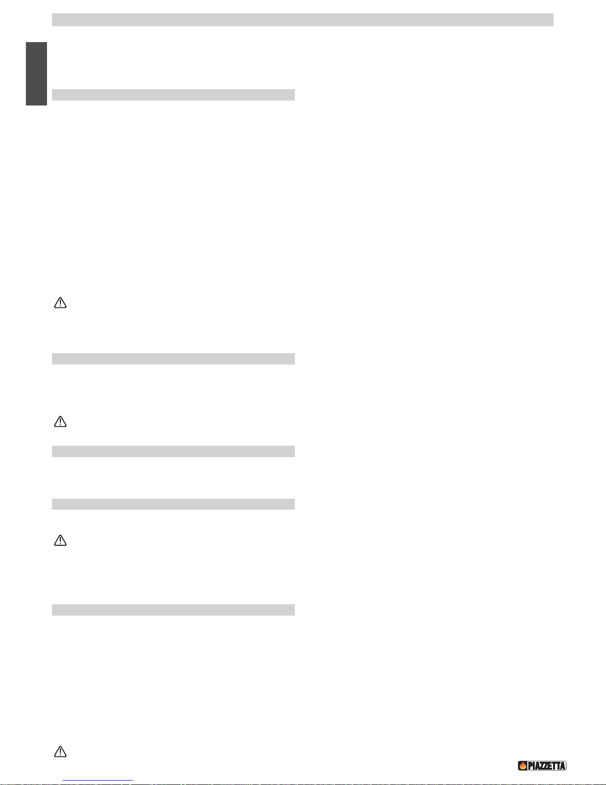
24
Italiano
4.0 MANUTENZIONE
4.1 Controllo periodico
Determinare le eventuali formazioni di creosoto nei tubi di collegamento alla canna fumaria e nella canna fumaria durante le stagioni di
funzionamento dell’apparecchio, ispezionandoli almeno una volta ogni due mesi.
La combustione della legna produce pece e altri vapori organici i quali (soprattutto se con percentuali di umidità superiori al 30%) danno
origine al “creosoto”. La formazione del creosoto provoca incrostazioni con la conseguente ostruzione della canna fumaria ed
impedimento del passaggio dei fumi.
Il “creosoto” è un elemento infiammabile, la sua autoaccensione può provocare seri danni alla canna fumaria ed alla struttura dell’abitato.
Utilizzare solo combustibili consigliati (Vedi paragrafo “Combustibili”).
Se il creosoto si è accumulato, questo deve essere rimosso per ridurre il rischio di incendio e per favorire lo scambio termico.
Devono essere sempre liberi da ostruzioni e ispezionati almeno una volta ogni due mesi:
- Il condotto di evacuazione fumi (collegamento alla canna fumaria, canna fumaria, comignolo);
- la presa d’aria esterna;
-
il focolare dell’apparecchio (corretto posizionamento delle piastre, del cassetto cenere, del piano fuoco e della griglia, dei deflettori/e fumi, ecc.);
- il sistema di ventilazione (bocchette, canali di conduzione dell’aria, griglie) se installato.
Verificare che il sistema di chiusura automatico dell’anta e dei registri aria funzionino in modo corretto.
La manutenzione di tutto il sistema di riscaldamento sopraccitato deve essere fatta obbligatoriamente almeno una volta l’anno,
e prima della stagione di messa in funzione. Consigliamo inoltre di controllare periodicamente tutto il sistema di riscaldamento
durante il periodo di funzionamento del focolare fino alla stagione di inattività.
4.2 Pulizia del rivestimento in ceramica
Il rivestimento in ceramica deve essere pulito con un panno morbido e asciutto prima di utilizzare qualsiasi detergente (anche se delicato).
In commercio esistono prodotti idonei alla pulizia delle ceramiche o concentrati per grès porcellanati, che possono rimuovere anche
macchie di olio, inchiostro, caffè, vino, ecc.
Non bagnare e non pulire mai la ceramica con acqua fredda quando questa è calda, lo shock termico potrebbe romperla.
4.3 Pulizia delle parti in acciaio inox
Le parti in acciaio inox del rivestimento devono essere pulite con un panno morbido ed asciutto prima di utilizzare eventuali detergenti.
In seguito a questa operazione è consigliato utilizzare un detergente sgrassante come acetone o aceto diluito con acqua.
4.4 Pulizia delle parti in metallo verniciato
Per pulire le parti in metallo verniciate del prodotto usare un panno morbido inumidito con acqua.
Non pulire mai le parti in metallo con alcool, diluenti, benzine, acetoni o altre sostanze sgrassanti o abrasive.
In caso d’uso di tali sostanze la ditta costruttrice declina ogni responsabilità per i danni provocati.
Eventuali variazioni di tonalità delle parti in metallo possono essere imputabili ad un uso non adeguato del prodotto.
4.5 Pulizia del vetro (GIORNALIERA)
La pulizia del vetro deve essere fatta a freddo con sostanze sgrassanti a base di ammoniaca e non corrosive come il diluente.
Se il riscaldamento dell’apparecchio in fase di accensione risulta essere molto lento a causa di legna non secca, è probabile che sul vetro si
accumuli catrame che si brucerà con l'apertura dell'aria secondaria o con il funzionamento ottimale dell’apparecchio. Se lasciate che il catrame
si accumuli per troppo tempo, farete più fatica a rimuoverlo, quindi consigliamo di fare una pulizia giornaliera del vetro prima dell’accensione.
Rottura del vetro
Tutti i nostri focolari con porta sono dotati di un vetro ceramico di spessore 4 mm, resistente ad uno shock termico di 750° C, questo
può essere rotto solamente a causa di un forte impatto, ad esempio sbattendo troppo forte la porta.
In caso di rottura sostituire il vetro solo con materiale originale del Gruppo Piazzetta S.p.A.
Non usate comunque materiali che possono graffiare o rovinare i vetri, in quanto le graffiature possono diventare crepe o rotture.
• Tutte le operazioni di manutenzione (pulizia, eventuali sostituzioni, ecc...) vanno effettuate a fuoco spento e quando l’apparecchio è freddo.
Inoltre non usare in nessun caso sostanze abrasive.
DT2010057-00
DT2010393-00
Page 25
Italiano
25
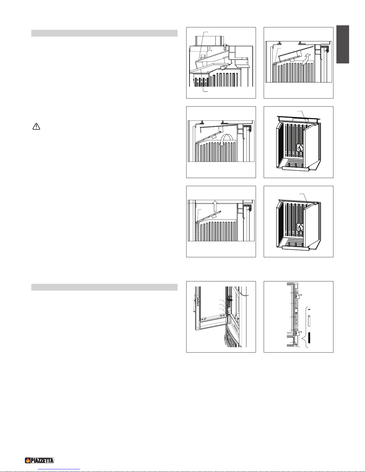
4.6 Rimozione deflettori
Per la pulizia del focolare ricordarsi di togliere anche i 2 deflettori fumi
(nel modello e911 è presente un solo deflettore).
Per questa operazione si consiglia di essere in due persone, quindi:
-
sollevare anteriormente i due deflettori facendo perno sullo schienale;
-
tenendo fermo con una mano lo schienale, rimuovere uno alla volta i
due laterali sempre sostenendo i deflettori fumi; estrarli dal focolare
tenendoli inclinati;
-
abbassare cautamente i due deflettori fumi verso il piano fuoco ed
estrarli sempre cautamente uno alla volta ruotandoli fino a trovare la
giusta inclinazione per farli uscire dalla bocca del focolare;
Lo schienale è libero e potrebbe cadere.
-
quindi pulirli e rimontarli con ordine inverso.
4.7 Chiusura automatica porta
Per togliere la porta è sufficiente, dopo aver svitato le viti indicate in
figura, sfilare i perni delle cerniere.
Nel rimontaggio è necessario caricare la molla per garantire la
chiusura automatica:
- inserire sulla cerniera superiore il proprio perno e bloccarlo con la
vite;
- inserire la molla, bussola e relativo tubo nel vano della zona
inferiore della porta;
- infilare il perno cerniera inferiore e ruotarlo sino ad agganciare le molla (osservate l’accoppiamento attraverso il foro sul tubo);
- tenendo premuto il perno e usando la chiave in dotazione, ruotarlo come indicato in figura finché consentito e, bloccarlo con la relativa
vite; ripetere quindi l’operazione per altre 2-3 volte;
- verificare con la dovuta attenzione se la chiusura automatica della porta è garantita, altrimenti caricare ulteriormente la molla.
DT2030763-00
Fig. 34
DT2030764-00
Fig. 35
DT2030765-00
Fig. 36
DT2030766-00
Fig. 37
DT2030767-00
Fig. 38 - e911
DT2030768-00
Fig. 39 - e911
DT2030769-00
Fig. 40
DT2030770-00
Fig. 41
Deflettore fumi superiore
Deflettore fumi inferiore
Schienale
Laterale
Laterale
Schienale
Perno
Grano
Tubo con
molla
Rondella
Rondella
Perno fermo
molla
Perno
cerniera
superiore
Perno
cerniera
inferiore
Grano
Bussola
Tubo
Molla
Grano
Grano
Page 26
26
Italiano
4.8 Pulizia del focolare e del cassetto cenere (GIORNALIERA)
La pulizia del focolare e del cassetto cenere deve essere giornaliera. L’utilizzo del focolare per una intera giornata contribuisce all’accumulo
di ceneri o residui della combustione.
La non curanza di questo comporta un eccesso di residui dell’apparecchio, che andranno ad aggravare il buon funzionamento del prodotto.
Anche il cassetto cenere necessita di tale cura, se dovesse riempirsi o ad andare ad ostruire la griglia del focolare, avremo un inadeguato
funzionamento del prodotto.
4.9 Pulizia dell'Aluker
®
La parte interna del prodotto è costruito da un materiale di nuova concezione denominato “Aluker®”.
L’ “Aluker
®
” è un materiale a base di sostanze assolutamente atossiche resistente al calore (fino a 1400°).
Nonostante la buona resistenza meccanica è comunque raccomandabile non gettare con forza legna di grosso taglio sulle piastre stesse.
L’“Aluker
®
” durante l’accensione si annerisce, per poi tornare al colore naturale man mano che le piastre si riscaldano.
Alcuni consigli per un buon utilizzo delle piastre in “Aluker
®
” sono:
- non gettare acqua per lo spegnimento del fuoco, lasciando che le piastre si raffreddino da sole;
- non graffiare le piastre in “Aluker
®
” con corpi metallici.
Per la pulizia delle piastre in “Aluker
®
” usare un semplice scopino.
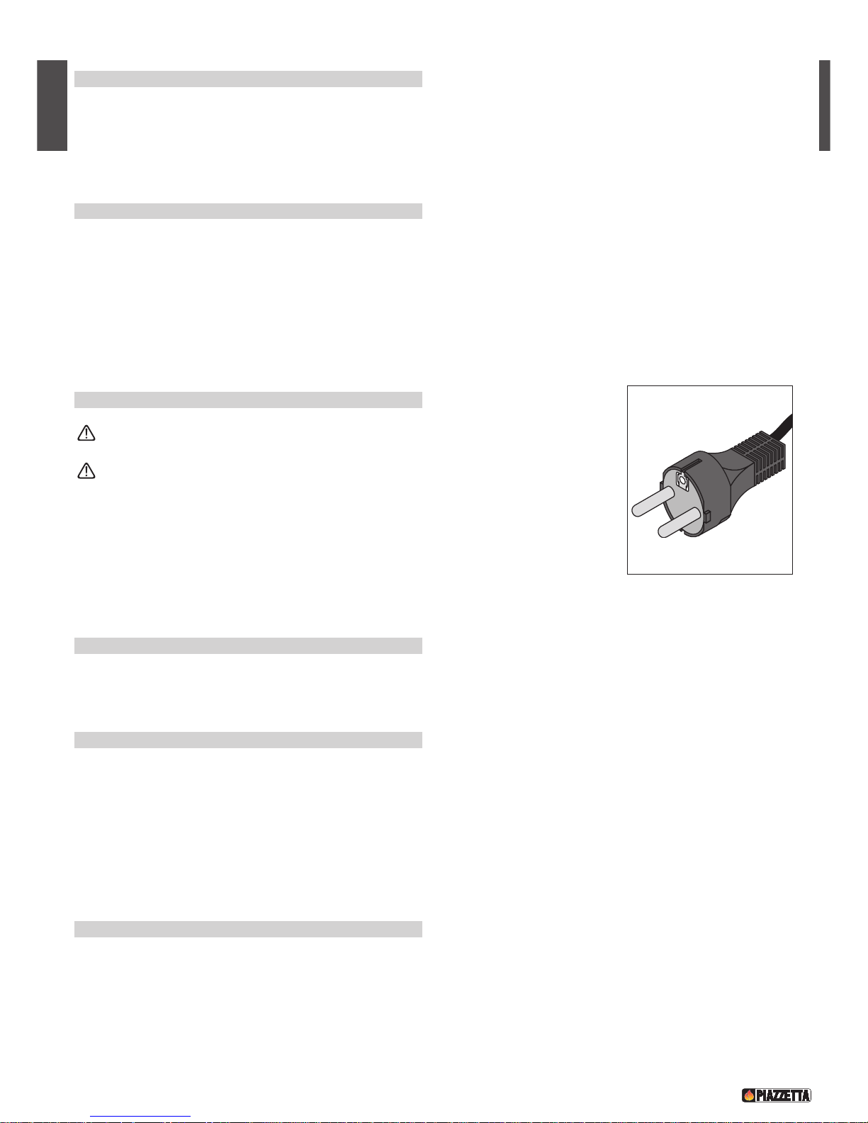
4.10 Pulizia del ventilatore (ANNUALE) - Fig. 34
Ogni operazione di pulizia e/o manutenzione va effettuata a CORRENTE DISINSERITA.
In relazione alle norme vigenti sulla sicurezza degli apparecchi elettrici, per tutte le operazioni
di installazione, manutenzione o intervento che comportano l’accesso a parti elettriche è
obbligatorio rivolgersi ad un Centro Assistenza Tecnica Piazzetta o a personale qualificato.
Il kit di ventilazione necessita di una pulizia annuale da eventuali depositi di polvere che si formano nelle
fessure della protezione, nelle griglie e nelle pale del ventilatore. Questa operazione è facilitata con
l’utilizzo di un aspirapolvere o di aria compressa. Fare attenzione alle parti elettriche.
Per una corretta pulizia del ventilatore è necessario smontare il kit di ventilazione. Eseguire le stesse
operazioni per l’installazione fatte a ritroso (vedi istruzioni allegate al Kit stesso).
4.11 Verifica guarnizione
Una buona tenuta della guarnizione della porta può mantenere il rendimento ottimale del prodotto. Quindi verificare periodicamente o dopo
un lungo periodo di funzionamento che la guarnizione non sia logora o danneggiata. In tal caso sostituirla con il ricambio originale del
Gruppo Piazzetta S.p.A.
4.12 Inattività del prodotto
Se è prevista l’inattività del prodotto per un lungo periodo consigliamo di pulire completamente il focolare, onde evitare incrostazioni e ossidazioni
difficili da pulire, e di effettuare a titolo preventivo un controllo generale come riportato al paragrafo “Controllo periodico”.
Dopo un lungo periodo di inattività del prodotto prima di accendere il focolare si consiglia di osservare quanto citato al paragrafo “Controllo periodico”.
Dopo un periodo di inattività del prodotto, il problema delle dilatazioni dei materiali e dell’esalazioni dei vapori odorosi potrebbero ripresentarsi,
quindi è consigliato riavviare l’apparecchio non portandolo immediatamente a regime, non attivando il sistema di ventilazione forzato fino a
quando l’esalazioni dei vapori sia terminata. Per ovviare il problema è sufficiente aerare il locale.
4.13 Smaltimento delle ceneri
Le ceneri devono essere poste in un contenitore in metallo con coperchio a tenuta. Fino allo spegnimento definitivo delle braci, il contenitore
chiuso deve essere posto su una base non combustibile e ben lontano da materiali combustibili.
Le ceneri solo quando sono spente possono essere gettate nel contenitore per i rifiuti organici, ovviamente in assenza di chiodi o materiali non organici.
Le ceneri di legna naturale (non trattata) derivante dalla combustione di stufe o caminetti è composta principalmente da: ossidi di calcio, silicio, potassio,
magnesio. Perciò la cenere può essere dispersa come fertilizzante per le piante o per il vostro giardino non superando ogni anno i 2,6kg su 10m2.
DT2030069-00
Fig. 42
Page 27
Italiano
27
Italiano
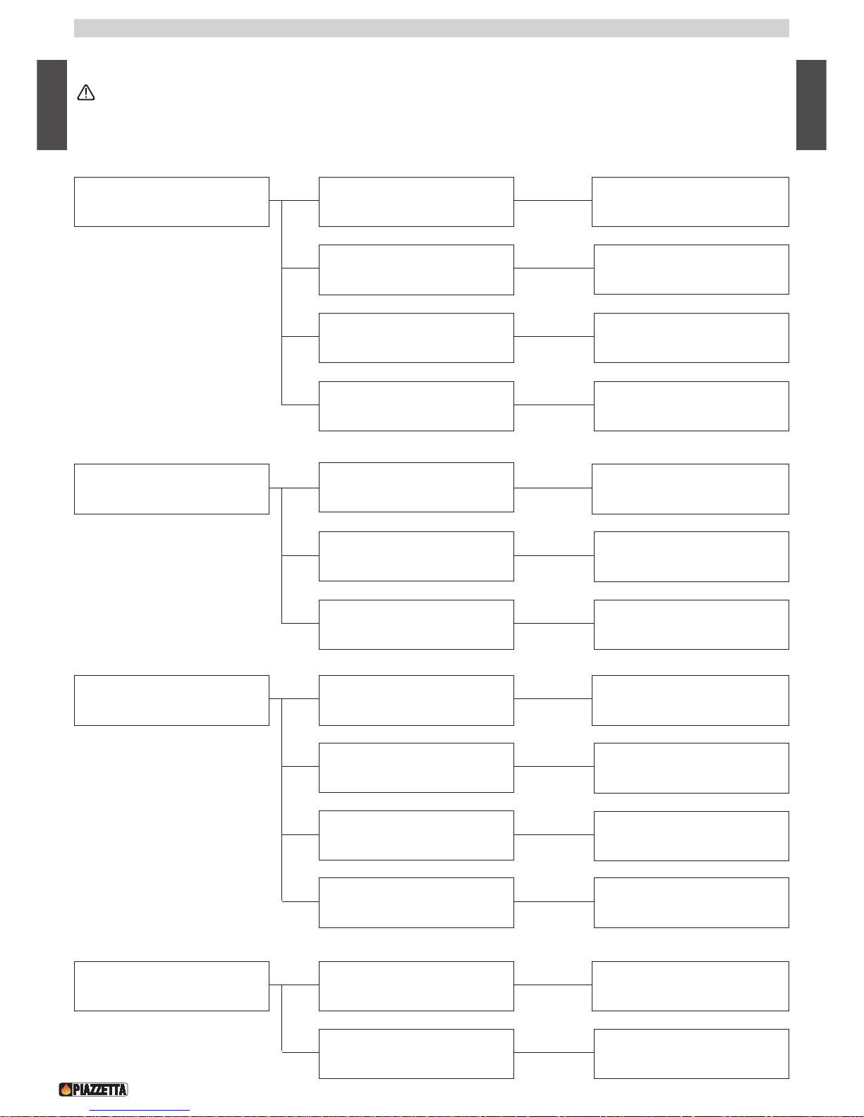
5.0
PRINCIPALI ANOMALIE
DT2010069-00
Tutte le operazioni devono essere effettuate esclusivamente in sicurezza, ad apparecchio freddo, in assenza di corrente
(staccare la spina), e da personale qualificato.
Problema Causa Soluzione
Il Vetro si sporca eccessivamente
Mancanza di tiraggio
Controllare il condotto di scarico
fumi
Legna umida
Utilizzare legna secca
Utilizzo di combustibili di classe
mediocre o cattiva
Cambiare il tipo di combustibile (vedi
paragrafo “Combustibile”)
Poca aria comburente
Aprire in maggior misura i registri
aria
Si forma condensa
Sezione della canna fumaria troppo
grande
Ridurre la sezione inserendo un condotto
di sezione appropriata e ben isolato
all’interno della canna fumaria
Canna fumaria non isolata
adeguatamente
Provvedere a rivestire la canna fumaria con
tavelle o altri materiali isolanti
Combustione lenta e quindi
temperatura fumi bassa
Bruciare legna di più piccolo taglio e secca
Aprire in maggior misura il registro
aria primaria
Fuoriuscita di fumo dal focolare nelle
condizioni atmosferiche avverse
Comignolo non antivento
Sostituire il comignolo con uno
antivento
Canna fumaria non isolata
adeguatamente
Provvedere a rivestire la canna fumaria con
tavelle o altri materiali isolanti
Difficoltà di accensione
Registri aria chiusi
Portare in posizione massima i
registri aria comburente
Legna di pezzatura troppo grande
Usare legna di pezzatura più piccola
Legna troppo umida
Bruciare legna più secca
Mancanza di tiraggio Controllare il condotto scarico fumi
Page 28
28
Italiano
Problema Causa Soluzione
Il focolare non scalda
Quantità di legna inferiore a quella
necessaria per ottenetre le resa
nominale
Usare la quantità di legna indicata
nelle istruzioni (Vedi paragrafo
“Regolazione aria comburente”)
Focolare sottodimensionato per
l’ambiente da riscaldare
Integrarlo con un’altra fonte di
riscaldamento
Isolamento non adeguato dell’ambiente
in cui è installato il caminetto o la stufa
Provvedere ad un buon isolamento
con materiali idonei
Presa d’aria esterna
sovradimensionata
Diminuire la sezione d’ingresso
Dalle bocchette esce poca aria
e poco calda
Condutture non isolate
Provvedere ad un adeguato
isolamento
Condutture con percorso troppo
lungo e/o con troppe curve
Modificare il percorso e attenersi al
libretto di istruzioni del kit di
ventilazione
Troppe diramazioni Modificare il percorso
Ambiente sovradimensionato rispetto
alla portata del ventilatore e alla
potenza dell’apparecchio
Riscaldare meno ambienti o usarlo
come integrazione
Il ventilatore non funziona (*)
Errato collegamento
dell’alimentazione
Eseguire un allacciamento corretto
secondo lo schema di montaggio
Regolatore elettronico danneggiato Sostituire il regolatore
Manca alimentazione elettrica Alimentarlo
Ventilatore rumoroso (*)
Presenza di polvere o altro nel
ventilatore
Pulire il ventilatore
Vibrazioni
Controllare il posizionamento del
ventilatore
Usura delle parti rotanti
Provvedere alla manutenzione delle
parti usurate
Sostituire il ventilatore
Page 29
Italiano
29
Problema Causa Soluzione
Uscita fumi all’apertura dell’anta
Apertura troppo veloce
Tenere l’anta socchiusa per pochi
secondi prima della completa
apertura
Le fiamme sono ancora vive
Aprire la porta solo quando sul piano
fuoco rimangono le braci
(*) In relazione alle norme vigenti sulla sicurezza degli apparecchi elettrici, per tutte le operazioni di installazione,
manutenzione o intervento che comportano l’accesso a parti elettriche è obbligatorio rivolgersi ad un Centro Assistenza Tecnica
Piazzetta o a personale qualificato.
Page 30

30
English
Dear Customer,
We thank you for having chosen one of our products, the fruit of extensive and continuous research for a superior product in terms of
safety, reliability and performance.
In this manual you will find all the information and advice you need to use your product as safely and efficiently as possible.
DT2010001-00
IIMPORTANT INFORMATION
DT2010021-00
REFERENCE STANDARDS:
DT2010028-02
Plans and diagrams are supplied as examples at the manufacturer’s discretion; in the pursuit of a policy of continuous development and
innovation the manufacturer may, without prior warning, make any modifications deemed appropriate.
This document is the property of Gruppo Piazzetta S.p.A.; it may not be divulged in part or in whole to third parties without written
permission from Gruppo Piazzetta S.p.A. Gruppo Piazzetta S.p.A. reserves all its statutory rights.
•
This manual has been prepared by the manufacturer and
constitutes an integral part of the product, and must accompany it
throughout its life. In the event of sale or relocation of the product
make sure this booklet accompanies it, since the information
contained in it is addressed to the purchaser and to anyone
involved in the installation, use and maintenance of the product.
• Read the instructions and the technical information contained in
this manual carefully, before proceeding with installation, use or
any repairs.
• The observance of the instructions and technical information in
this manual guarantees the safety of the user and the product, a
more efficient operation and an increased lifespan.
• The product’s installation and use should conform to the
manufacturer’s instructions and to local bylaws.
• Careful planning and safety analysis on the part of Gruppo
Piazzetta S.p.A. have resulted in a safe product. However, when
carrying out any operation we recommend that you follow
carefully the instructions contained in this manual, and that you
keep it at your disposal.
• Before installing the product read all instruction booklets relevant
to the cladding, the ventilation kit and any other accessory.
• Be especially careful when moving any ceramic components.
• Check that the floor where the product is to be installed is exactly
level.
• To help correct potential unevenness and irregularities a sheet of
adhesive fibreglass accompanies the product.
• Do not block the electrical socket; it should be close to the unit
but accessible.
• The wall where the product is to be placed should not be of wood
or any other flammable material; furthermore it is important to
maintain safety distances (refer to section entitled ‘Prevention of
domestic fires’ contained in the stove’s manual for use and
maintenance).
• The assembly of the cover should be undertaken by two people
(follow the assembly instructions in the attached booklet).
• Keep children informed of safety measures to be followed when
the stove is operational and at other times.
UNI EN 832 . . . . . . . . . . . . . . . . . . . . . . . . Thermal performance of buildings - Calculation of energy use for heating
UNI EN 13240 . . . . . . . . . . . . . . . . . . . . . . Roomheaters fired by solid fuel - Requirements and test methods
UNI 10683 . . . . . . . . . . . . . . . . . . . . . . . . . Heating appliances fired by wood or other solid biofuels
UNI EN 13384 . . . . . . . . . . . . . . . . . . . . . . Chimneys - Thermal and fluid dynamic calculation methods
UNI 10847 . . . . . . . . . . . . . . . . . . . . . . . . . Chimneys for generators feeded with liquid and solid flues - Maintenance and inspection
Guidelines and procedures
UNI EN 1856-1-2 . . . . . . . . . . . . . . . . . . . . Chimneys – Requirements for metal chimneys
UNI EN 1443 . . . . . . . . . . . . . . . . . . . . . . . Chimneys – General requirements
UNI 7129 . . . . . . . . . . . . . . . . . . . . . . . . . . Gas plants for domestic use fed by network distribution
DIN 18 891 . . . . . . . . . . . . . . . . . . . . . . . . Solid-fuel stoves with flue
DIN 51731 class of measurement HP2 . . Fuels
Page 31
English
31
INDEX
DT2010187-01
Section Title Page code
1.0 General rules 32 DT2010444-00
1.1 Single flueway or chimney 33 DT2010024-01
1.2 Soot inspection 33 DT2010031-00
1.3 Chimney stack 34 DT2010025-00
1.4 Fresh air intake 35 DT2010026-00
1.5 Installation environment 36 DT2010215-01
1.6 Capacity load of the floor 36 DT2010032-00
1.7 Heating capacity 36 DT2010130-00
1.8 Minimum safety distances 37 DT2010034-00
1.9 Connection to the flue 37 DT2010445-00
1.10 Prevention of domestic fires 40 DT2010027-00
2.0 Technical data and specifications 41 DT2010446-01
2.1 Description of the appliance 41 DT2010847-00
2.2 Accessories 44 DT2010452-00
2.3 Features 44 DT2010450-00
2.4 Product identification 44 DT2010041-04
2.5 Technical data 45 DT2010451-01
2.6 Dimension e911 46 DT1020016-00
2.7 Dimension e912 46 DT1020017-00
2.8 Dimension e915 46 DT1020095-00
2.9 Dimension e917 46 DT1020232-00
2.10 Dimension e918 47 DT1020270-00
2.11 Dimension e920 47 DT1020015-00
2.12 Dimension e922 47 DT1020231-00
2.13 Dimension e923 47 DT1020271-00
3.0 Use 48 DT2010453-00
3.1 Fuel 48 DT2010043-00
3.2 Adjusting the combustion air 49 DT2010462-00
3.3 Lighting for the first time 49 DT2010045-00
3.4 Lighting 50 DT2010044-02
3.5 Opening the door 50 DT2010046-00
3.6 Nighttime operation at minimum 50 DT2010047-00
3.7 Operation under adverse weather conditions 51 DT2010048-00
3.8 Overheating and Extinguishing 51 DT2010051-00
3.9 Humidifier 51 DT2010464-00
3.10 Using the oven 51 DT2010395-00
4.0 Maintenance 52 DT2010463-00
4.1 Periodic control 52 DT2010058-00
4.2 Cleaning the ceramic cladding 52 DT2010059-01
4.3 Cleaning the steel parts 52 DT2010060-00
4.4 Cleaning the painted metal parts 52 DT2010061-01
4.5 Cleaning the glass (DAILY) 52 DT2010062-01
4.6 Removal of smoke deflectors 53 DT2010443-00
4.7 Door assembly 53 DT2010442-00
4.8 Cleaning the grate and the ash tray 54 DT2010063-00
4.9 Cleaning Aluker
®
54 DT2010064-00
4.10 Cleaning the fan 54 DT2010065-01
4.11 Seal control 54 DT2010165-00
4.12 Shutting down 54 DT2010068-00
4.13 Disposal of ashes 54 DT2010049-01
5.0 Troubleshooting 55 DT2010069-00
Declaration of conformity stove e911 57 DT2010702-00
Declaration of conformity stove e915-e917-e918 58 DT2010703-00
Declaration of conformity stove e912-e920-e922-e923 59 DT2010704-00
This booklet code H07020320 / DT2000212 - Rev. 01-(05/2007) comprises 60 pages.
Page 32
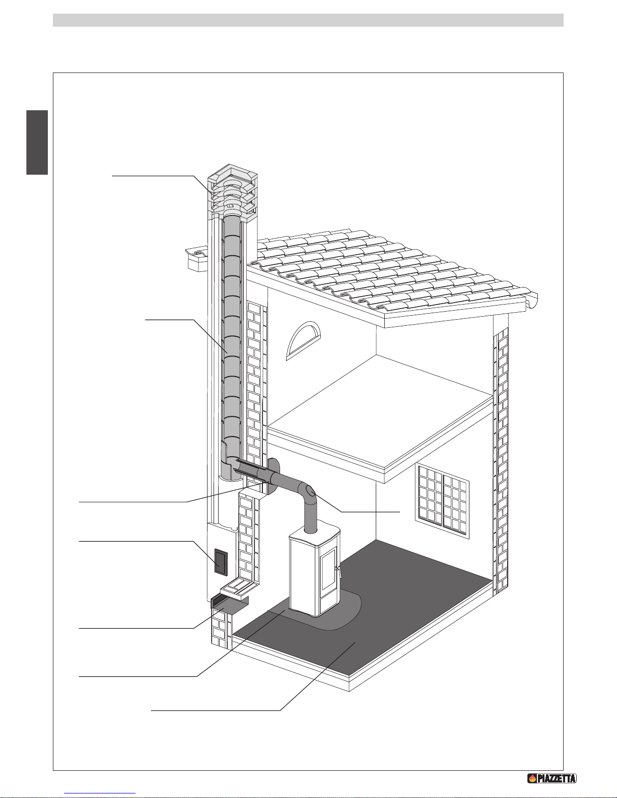
32
English
1.0 GENERAL RULES
DT2010444-00
DT2030048-00
CHIMNEY STACK
FLUE
CONNECTION TO FLUE
SOOT REMOVAL
INSPECTION HOLE
FRESH AIR INTAKE
CHECK OF FLOOR
LOAD-BEARING CAPACITY
SAFETY DISTANCES
INSPECTION
HOLE
Ensure that the installation of your product conforms to all the following instructions.
Fig. 1
Page 33
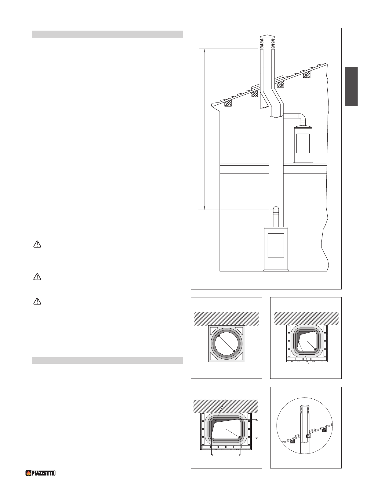
English
33
NO
X
Minimum 3,5 m
MAX 45
NO
1.1 Single flueway or chimney - Fig. 2 - 6
Every appliance must have a vertical flue pipe operating by natural
draught to discharge the combustion gases outdoors.
The flue must:
- comply with regulations in force in the place of installation of the
appliance;
- be tight to the products of combustion, waterproof, suitably
insulated, made with materials resistant to the corrosion of the
gases and to stress;
- be connected to just one stove, fireplace or extraction hood;
- be properly sized, with constant free internal section, equal to or
greater than the diameter of the flue pipe of the stove and at least
3.5 m in length;
- be mainly in a vertical position with a deflection from the axis of
no more than 45° (Fig. 2);
- be at a suitable distance from combustible or flammable
materials, ensured by an air gap or suitable insulating material;
- be of uniform internal section, preferably round. Square or
rectangular sections must have rounded corners with a radius of
at least 20mm and a maximum ratio between the sides of 1.5
(Fig. 4). The walls must be smooth if possible and without
narrowing. Bends must be regular and without discontinuity (Fig.
3 - 4 - 5).
It is forbidden to make fixed or mobile apertures on the flue
pipe to connect appliances other than the one to which it is
already connected.
It is forbidden to pass other air ducts or service pipes inside
the flue pipe, however large it is.
If the flue pipe is an incorrect size or installed other than in
compliance with the above instructions, Gruppo Piazzetta
S.p.A. cannot be held liable for malfunctioning of the
product, damage to property or injury to persons or
animals.
1.2 Soot inspection Fig. 1
- The flue must have a chamber for collecting solid matter and any
condensate located below the connection and which may be
easily inspected by means of an airtight door. (Fig.1)
- The bends connecting to the flue must have inspection points
that allow the system to be checked, cleaned and maintained.
Ø
DT2030050-00
DT2030049-00
Fig. 3
P
R (min. 20)
L (<_ 1,5 x P)
Deposit of creosote
DT2030189-00
Fig. 5
R (min. 20)
Deposit of creosote
DT2030188-00
Fig. 4
Fig. 2
DT2030190-00
Fig. 6
Page 34
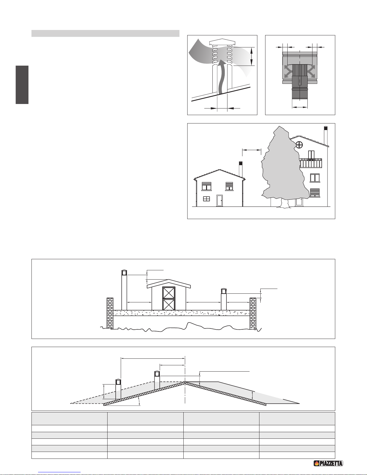
34
English
1.3 Chimney stack - Fig. 7 - 11
The flue must be fitted at the top with a device called a chimney stack,
designed to aid dispersion of the products of combustion in the
atmosphere.
The chimney stack must comply with the following requirements:
- it must have an internal section and shape the same as the flue;
-
it must have a useful outlet section of not less than twice that of the flue;
- the part of the flue that emerges from the roof or remains in contact
with the outside (e.g. in the case of an open loft), must be covered
with brick or tile elements and well insulated. It must be built in such
a way as to prevent the penetration of rain, snow and foreign matter
into the flue and to ensure that in the event of winds from all
directions and angle, discharge of the combustion products is
assured (chimney stack with down-draught cowl);
- any buildings or other obstacles that are higher than the chimney
stack must not be too close to the actual stack Fig.9;
-
the chimney stack must be positioned in such a way as to ensure
adequate dispersion and dilution of the products of combustion and
outside the reflux area. The size and shape of this area differ according
to the angle of inclination of the roof and it is therefore necessary to
adopt the minimum heights shown in Fig.10-11;
Example: Check the slope of the roof (column α), and the
anticipated distance of the chimney stack from the axis of the ridge
(column A); if the distance is greater than “A” the height of the
chimney stack may be read in (column H); if the distance is less
than “A” the chimney stack must rise above the ridge by 0.5
metres.
6-8 m
DT2030052-00
Fig. 9
FLAT ROOF
0.50 m
0.50 m
over 5 m
m or less
5 m
m or less
5 m
DT2030053-00
Fig. 10
SLOPING ROOF
0.50 m above the ridge
height of reflux
area Z
ridge axis
distance more than A
α
H min.
distance
min. than A
Fig. 11
Pitch of the roof
Horizontal width of reflux
area from ridge axis
Minimun height of
outlet from roof
Height of reflux area
α
A H minimo Z
15° 1,85 m 1,00 m 0,50 m
30° 1,50 m 1,30 m 0,80 m
45° 1,30 m 2,00 m 1,50 m
60° 1,20 m 2,60 m 2,10 m
A
B*
* B equivale al
doppio di A
DT2030051-00
Fig. 7
A
BB
DT2030191-00
Fig. 8
DT2030192-00
Page 35
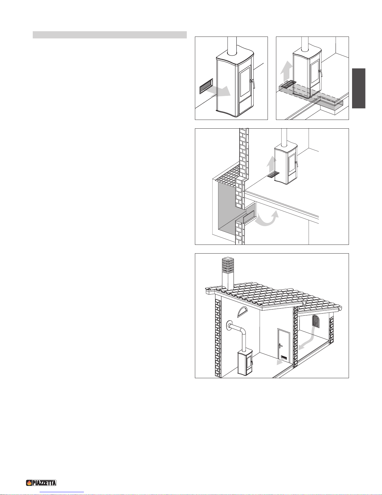
English
35
1
.4 Fresh air intake - Fig. 12 - 15
The stove/fireplace must have the necessary air available to ensure
proper combustion.
- Make sure that the room in which the stove/fireplace is to be
installed has an air intake of at least the size indicated in the
paragraph “Technical data”.
- The fresh air intake may be protected by an external grille provided
it does not reduce the minimum section of the recommended
airflow and is in a position whereby it cannot be obstructed.
The air necessary for the fire may be obtained in different ways:
- through an external grille direct to the room of installation (Fig. 12);
- with ducting through pipes direct to the room of installation,
increasing the recommended minimum free cross section by at
least 15% (Fig. 13);
- through a communicating hole from an adjacent room to the place
of installation: this system may only be used if the air flows freely
from the outside through fixed apertures (Fig. 14);
- from an adjacent room to the place of installation, but only if the air
flows freely through apertures communicating with the outside
(Fig. 15).
DT2030054-00
Fig. 12
DT2030194-00
Fig. 14
DT2030195-00
Fig. 15
DT2030193-00
Fig. 13
Page 36
36
English
1
.5 Installation environment
The appliance should be installed in a location which allows safe and convenient use as well as easy maintenance. If the product being installed
requires an electrical socket, the room must also be provided with an earthed power supply in accordance with current regulations.
The room where the appliance is to be installed or adjoining rooms must comply with the following requirements.
The installation of a wood-burning appliance in a bedroom, bath or shower room or in any room where another heating system not
equipped with its own air supply (fireplace, stove etc.) has already been installed is forbidden.
They must not be used as a garage, store for combustible material or for activities with a risk of fire.
They must not be in a vacuum in relation to the outside environment due to the effect of contrary draught caused by the presence
in the room where the stove is installed of another appliance or an extractor device.
Do not use two stoves, a fireplace and a stove, a stove and a wood-fired cooking range, etc. in the same environment, since the
draught of one could affect the draught of the other.
- Devices suitable for cooking food with relative hoods without an extractor fan may only be used in kitchens.
- Gas appliances of type C are allowed (refer to current legislation and regulations in the place of installation)
Gas appliances of type B are not allowed (refer to current legislation and regulations in the place of installation)
The stove or fireplace must not be used simultaneously with collective type ventilation ducts with or without extractor fan, other
devices or other appliances such as: forced ventilation systems or other heating systems using ventilation to change the air. Such
systems could cause a vacuum in the environment of installation even if installed in adjoining or communicating rooms.
1.6 Capacity load of the floor
Check the load-bearing capacity of the floor, referring to the weight of the product given in the paragraph
“Technical data”
.
If the floor does not have a suitable load-bearing capacity, adequate countermeasures must be taken, for example, by using a sheet metal
plate to distribute the load.
1.7 Heating capacity
Check the heating capacity of the appliance by comparing the rated power given in the paragraph
“Technical data”
with the power required
by the environment to be heated.
The energy requirement may be calculated approximately by multiplying the square metres of area by the height of the ceiling; the result
is then multiplied by a coefficient, which depends on the degree of insulation of the building, that is, on internal and external factors of
the dwelling:
a) Internal factors: type of window and door frames, thickness of the insulation and walls, type of building materials, presence of
stairwells, walls with extensive glazing, high ceilings, position of the rooms to be heated in relation to other adjacent heated or
unheated rooms, …
b) External factors: geographical position, average outdoor temperature, exposure, wind speed, latitude, altitude, …
Example of approximate calculation of the energy requirement to heat a fixed volume to 18/20° C:
The coefficient that is normally used is determined according to the real conditions as they occur case by case.
- From 0.04 to 0.05 kW per cubic metre in a well insulated environment
- From 0.05 to 0.06 kW per cubic metre in a poorly insulated environment
3 rooms measuring 20m2 X (H ceiling) 2.7m = 162 m3(volume)
In an environment with a good degree of insulation, an average value (coefficient) of 0.045 kW may be taken
162 (volume) X 0.045 (kW) = 7.3 kW necessary (6300 kcal/h)
Conversion 1kW = 860 kcal/h
Consult a heating technician or engineer for a correct check and calculation of the requirement of the environments to be heated
(see “Reference standards”).
Rated power being equal, products with the Multi-fire system can evenly distribute heat throughout the rooms to be heated.
Page 37
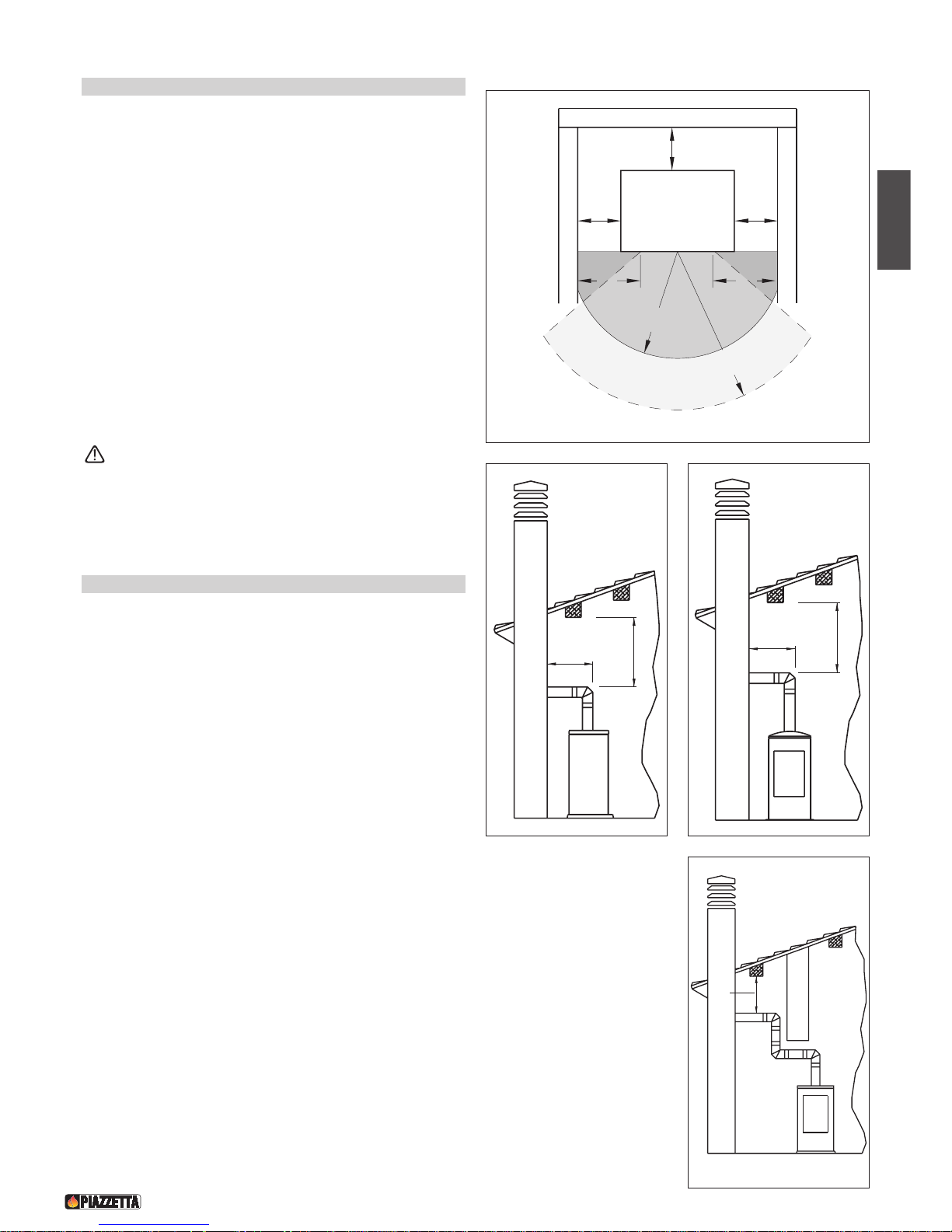
English
37
1.8 Minimum safety distances
With reference to the above diagram, the minimum safe distances
from heat sensitive or inflammable materials, such as load bearing
and other walls are:
A 20 cm. from the wall behind the stove
B 20 cm. from the side wall
C 100cm. in the radiating area
In the case of flooring that is heat sensitive or inflammable the floor
should be protected (using for example sheets of steel plate,
marble or tiles). The minimum distances are:
D 50 cm.
E 30 cm. (measured from the internal corner of the door opening)
Keep any combustible product well away from the stove
when it is lit (minimum distance from the heat radiation
area), for example: wooden furniture, curtains, carpets,
combustible liquids, etc.
1.9 Connection to the flue Fig. 17÷26
Two elbows at the most may be used in connecting the stove to the
flue, with a change in direction of no less than 90° and the length
of the horizontal section of flue pipe not exceeding 2 m. Figures 1718-19.
The pipe assembly must be as short as possible, without
constrictions and made in material resistant to corrosion by
combustion gases and to temperatures of 550-600° C.
It is advisable to use Gruppo Piazzetta S.p.A. pipes and elbows for
connection to the flue, since the appliance flue collar is sized for
insertion of these. Furthermore, the elbows have an inspection
door allowing control, cleaning and maintenance of the system.
Other pipes may also be applied after adaptation and checking that
the coupling is compatible, taking into account that the pipes and
elbows must be made in compliance with current regulations. In
this case, however, Gruppo Piazzetta S.p.A. only guarantees
trouble-free operation for its own products used in accordance
with instructions.
If elbows are used, if the flue pipe assembly does not rise up
straight, attention must be paid to checking that the connection can
withstand the overhead weight and does not require suitable
supporting systems.
R
a
d
i
a
t
i
n
g
z
o
n
e
Rear wall
Floor protection
A
B
B
E
D
C
STOVE
Side wall
Side wall
E
DT2030059-00
Fig. 16
MAX 2M
MIN 40 cm
Yes
DT2030056-00
Fig. 17
MAX 2M
MIN 40 cm
Yes
DT2030196-00
Fig. 18
MIN 40 cm
NO
DT2030197-00
Fig. 19
Page 38
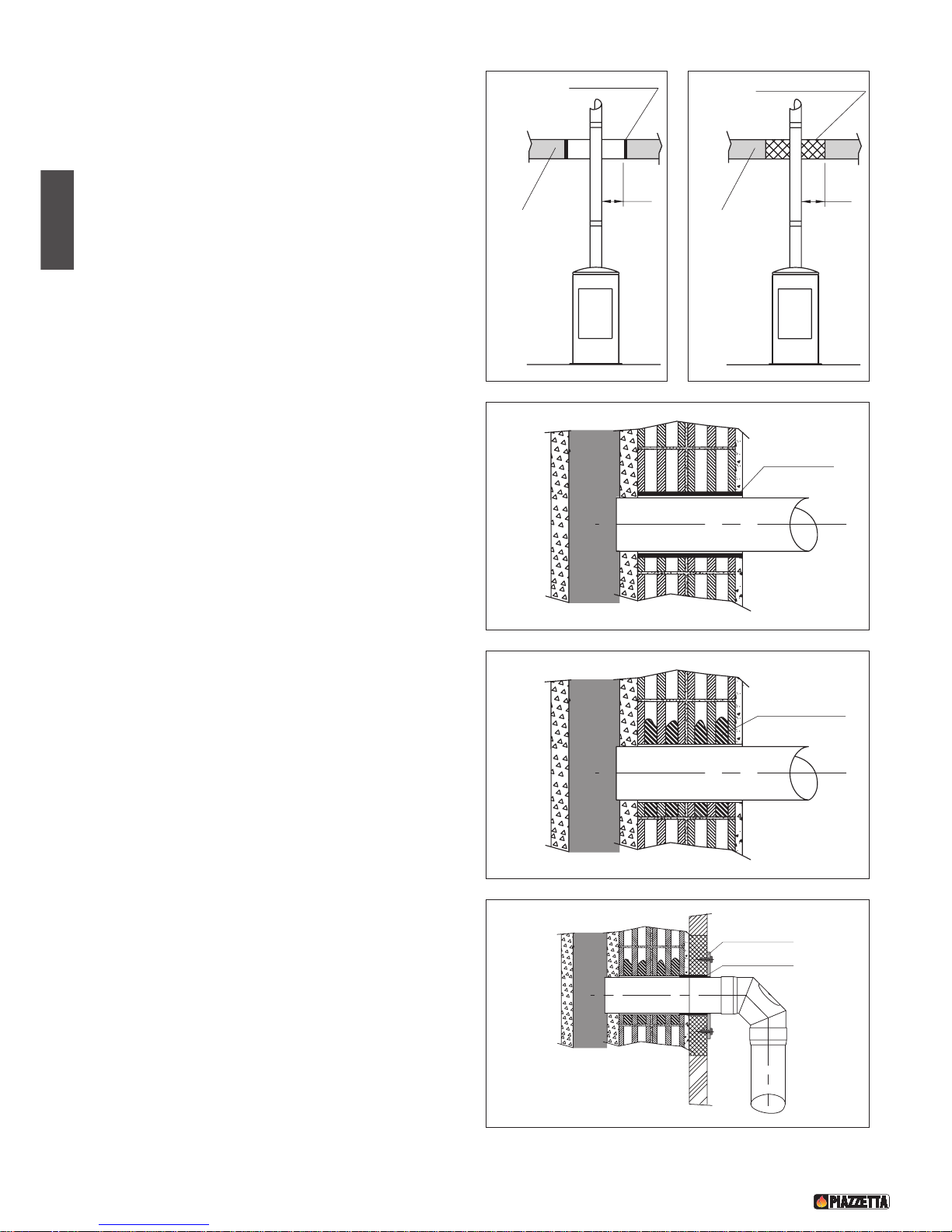
38
English
When connecting to the flue there must be a minimum clearance
of 40 cm from building elements sensitive to heat or from
combustible materials (cladding, wooden beams or ceilings, etc.).
See figures 17-18-19-25-26.
If the flue assembly passes through elements or walls in heat-sensitive
combustible material or through load-bearing walls, create:
- insulation of at least 20 cm around the flue pipe assembly (for
example cement mortar, lightweight concrete; Figures 21-25-26.
- otherwise the flue pipe assembly must remain at a safety distance
of 40 cm by inserting a tube of non-flammable and resilient
material. Figure 20.
If the flue pipe assembly passes through non-flammable masonry
or walls:
- the air gaps must be filled with non-flammable, resilient material
with a reduced heat transmission capacity (e.g. lightweight
concrete); Figure 23.
- otherwise the air gaps must be protected with special protective
tubes. Figure 22.
Check that the connection to the flue is properly sealed to ensure
there is no flue gas leak when the appliance is operating in a
vacuum.
Check that the pipe is not inserted too far into the flue, thereby
restricting the passage of flue gases. Figure 22-23.
BAFFLE PLATE
40 cm
COMBUSTIBLE
MATERIAL
DT2030057-00
Fig. 20
20 cm
INSULATING MATERIAL
COMBUSTIBLE
MATERIAL
DT2030199-00
Fig. 21
PROTECTIVE TUBE
FLUE
DT2030202-00
Fig. 22
FLUE
FILLER
DT2030203-00
Fig. 23
FLUE
TRIM COLLAR
WALL CONNECTOR PIPE
DT2030198-00
Fig. 24
Page 39
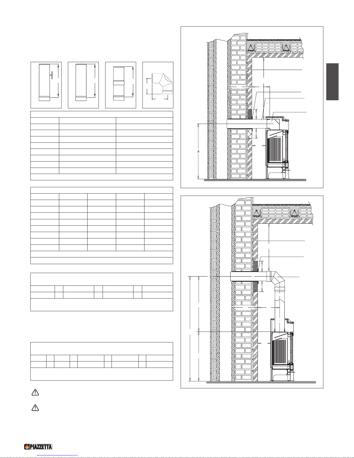
English
39
TOP - REAR flue gas outlet
IMPORTANT INFORMATION:
- Pipes with diameter 15 cm;
- 5cm must be deducted for each joint;
Having calculated the section of the hole for connection to the flue,
fix the trim collar and the wall connector pipe (Fig. 24).
Ensure that everything is installed in a workmanlike manner.
The measurements shown in the figures are approximate,
since appliance installation is envisaged in a place where
the floor is level and the wall at right angles to the floor.
TR100
95
DT2030060-00
T100
95
DT2030256-00
T50T50
90
DT2030201-00
24,5
24,5
C6
DT2030200-01
Approx. calculation of the section of vertical pipe knowing “H”.
Example: H = 80 cm
80 - 24,5 + 5 = 60,5
H Elbow C6 Pipe joint Pipe lenght
One 100 cm pipe “T100” should be cut to 60,5 cm
Cut the pipe from the spigot end
Approx. calculation of the section of horizontal pipe knowing “E”.
Example on stove e917: E = 50(cm), D = 38(cm)
50 + 38 - 24,5 + 5 = 68,5
E D Elbow C6 Pipe joint
Pipe lenght
One 100 cm pipe “T100” should be cut to 68,5 cm
Cut the pipe from the spigot end
TABLE REAR FLUE GAS OUTLET (Measurements in cm)
Model Measurement A Measurement B
e911 Not envisaged Not envisaged
e912 102 29,5
e915 85 26,5
e917 93 30
e918 85 26,5
e920 102 29,5
e922 100,5 30
e923 102 29,5
Calculation of the value “B” with a minum safety distance from the rear wall of 20 cm
TABLE TOP FLUE GAS OUTLET (Measurements in cm)
Model Measurement C Measurement D Measurement H Measurement F
e911 126,5 37,5 120 246,5
e912 93 37,5 120 213
e915 76,5 34,5 120 196,5
e917 83,5 38 120 203,5
e918 76,5 34,5 120 196,5
e920 93 37,5 120 213
e922 91,5 38 120 211,5
e923 93 37,5 120 213
Calculation of the value “D” with a minum safety distance from the rear wall of 20 cm
Calculation of the values “F” and “H” with a single one-metre pipe“TR100” and one elbow “C6”
B
Wall rose
Inflammable or
heat sensitive surface
Optional connector
40 mi n.
20
20
20
FLUE
E
Large pipe
DT2030738-00
Fig. 25
C
F
H
40 mi n.
Inflammable or
heat sensitive surface
Wall rose
Pipes
20
20
20
FLUE
E
D
DT2030739-00
Fig. 26
Page 40

40
English
1.10 Prevention of domestic fires
The product must be installed and used in compliance with the
manufacturer’s instructions and European and national standards
as well as local regulations.
when a flue pipe passes through a wall or a ceiling, special
installation methods must be applied (protection, thermal
insulation, distances from heat-sensitive materials, etc.)
See the paragraph “Connection to the flueway”
- It is also recommended that all elements made of combustible or
inflammable material, such as beams, wooden furniture,
curtaining, flammable liquids, etc. be kept outside the heat
radiation range of the stove and at a distance of at least 1m from
the heating block.
- For other information, see the paragraph “Safety distances” and
“Connection to the flueway”.
- The flue pipe, chimney stack, chimney and fresh air intake must
always be free of obstructions, clean and checked periodically,
that is, at least twice during the seasonal period from the lighting
of the stove and during its use. When the stove has not been used
for some time it is advisable to carry out the checks mentioned
above. For further information, consult a chimneysweep.
- Only use recommended fuels (See paragraph “Fuels”).
Page 41
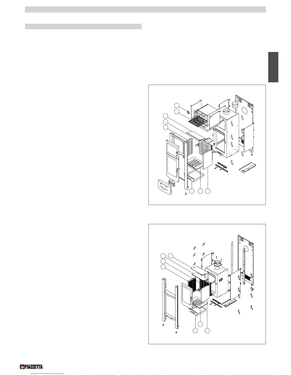
English
41
2.0 TECHNICAL DATA AND SPECIFICATIONS
DT2010446-01
2.1 Description of the appliance
Piazzetta stoves always offer cutting-edge technology in line with the strictest requirements in terms of thermal performance and
protection of the environment; with their aesthetic and functional features they represent an answer for truly special heating.
The external top quality majolica cladding stores the heat generated by the large radiating surfaces of the stoves and then gradually and
evenly releases this heat into the surrounding environment.
A majolica stove is not only attractive but also ensures that the quality of the air is good with the right degree of humidity.
The temperatures are not too high, thereby making the stove safer to use plus providing a feeling of pleasant, pervasive warmth.
Nr. Description . . . . . . . . . . . . . . . . . . . . . . . . . . . .Cod.
1 Aluker left side panel 282x430 e920 . . . . . . . . . . . . . . .1
2 Aluker back panel 415x410 e920 . . . . . . . . . . . . . . . . .1
3 Aluker right side panel 282x430 e920 . . . . . . . . . . . . . .1
5 Firebed e920 . . . . . . . . . . . . . . . . . . . . . . . . . . . . . . . . .1
6 Ashpan e920 . . . . . . . . . . . . . . . . . . . . . . . . . . . . . . . . .1
7 Lower smoke deflector e920 . . . . . . . . . . . . . . . . . . . . .1
8 Cooking grid e911 . . . . . . . . . . . . . . . . . . . . . . . . . . . . .1
9 Oven thermometer . . . . . . . . . . . . . . . . . . . . . . . . . . . .1
Nr. Description . . . . . . . . . . . . . . . . . . . . . . . . . . . .Cod.
1 Aluker left side panel 282x430 . . . . . . . . . . . . . . . . . . .1
2 Aluker back panel 415x410 e920 . . . . . . . . . . . . . . . . .1
3 Aluker right side panel 282x430 . . . . . . . . . . . . . . . . . .1
4 Firebed e920 . . . . . . . . . . . . . . . . . . . . . . . . . . . . . . . . .1
5 Ashpan e920 . . . . . . . . . . . . . . . . . . . . . . . . . . . . . . . . .1
6 Lower smoke deflector e920 . . . . . . . . . . . . . . . . . . . . .1
7 Upper smoke deflector e920 . . . . . . . . . . . . . . . . . . . . .1
5
5
4
3
6
2
1
7
8
DT2030756-00
7
6
2
1
5
4
3
DT2030757-00
e911
e912
Page 42
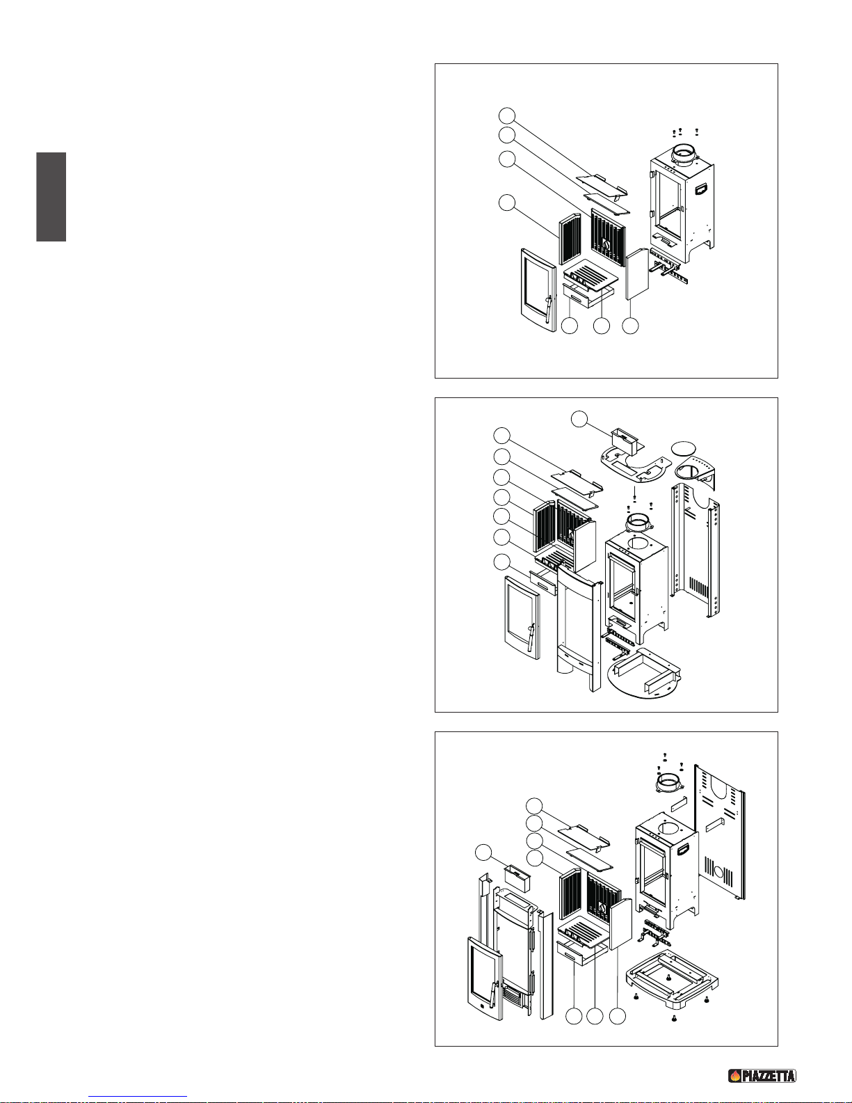
42
English
Nr. Description . . . . . . . . . . . . . . . . . . . . . . . . . . . .Cod.
1 Aluker left side panel 200x380 e915 . . . . . . . . . . . . . . .1
2 Aluker back panel 335x355 e915 . . . . . . . . . . . . . . . . .1
3 Aluker right side panel 200x380 e915 . . . . . . . . . . . . . .1
4 Firebed e915 . . . . . . . . . . . . . . . . . . . . . . . . . . . . . . . . .1
5 Ashpan e915 . . . . . . . . . . . . . . . . . . . . . . . . . . . . . . . . .1
6 Lower smoke deflector e915 . . . . . . . . . . . . . . . . . . . . .1
7 Upper smoke deflector e915 . . . . . . . . . . . . . . . . . . . . .1
Nr. Description . . . . . . . . . . . . . . . . . . . . . . . . . . . .Cod.
1 Aluker left side panel 200x380 e915 . . . . . . . . . . . . . . .1
2 Aluker back panel 335x355 e915 . . . . . . . . . . . . . . . . .1
3 Aluker right side panel 200x380 e915 . . . . . . . . . . . . . .1
4 Firebed e915 . . . . . . . . . . . . . . . . . . . . . . . . . . . . . . . . .1
5 Ashpan e915 . . . . . . . . . . . . . . . . . . . . . . . . . . . . . . . . .1
6 Lower smoke deflector e915 . . . . . . . . . . . . . . . . . . . . .1
7 Upper smoke deflector e915 . . . . . . . . . . . . . . . . . . . . .1
8 Humidifier reservoir e917 . . . . . . . . . . . . . . . . . . . . . . .1
Nr. Description . . . . . . . . . . . . . . . . . . . . . . . . . . . .Cod.
1 Aluker left side panel 200x380 e915 . . . . . . . . . . . . . . .1
2 Aluker back panel 335x355 e915 . . . . . . . . . . . . . . . . .1
3 Aluker right side panel 200x380 e915 . . . . . . . . . . . . . .1
4 Firebed e915 . . . . . . . . . . . . . . . . . . . . . . . . . . . . . . . . .1
5 Ashpan e915 . . . . . . . . . . . . . . . . . . . . . . . . . . . . . . . . .1
6 Lower smoke deflector e915 . . . . . . . . . . . . . . . . . . . . .1
7 Upper smoke deflector e915 . . . . . . . . . . . . . . . . . . . . .1
8 Humidifier reservoir e917 . . . . . . . . . . . . . . . . . . . . . . .1
5
34
1
7
6
2
DT2030758-00
e915
6
5
4
7
8
3
2
1
DT2030761-00
e917
34
5
2
6
7
8
1
DT2030762-00
e918
Page 43
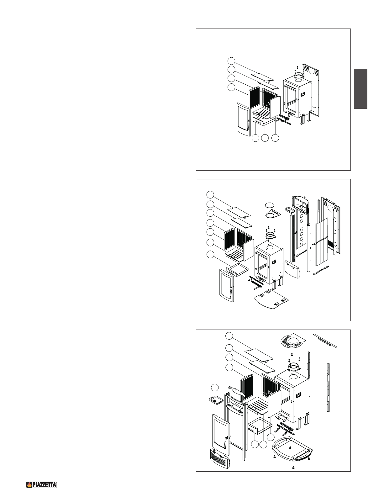
English
43
Nr. Description . . . . . . . . . . . . . . . . . . . . . . . . . . . .Cod.
1 Aluker left side panel 282x430 e920 . . . . . . . . . . . . . . .1
2 Aluker back panel 415x410 e920 . . . . . . . . . . . . . . . . .1
3 Aluker right side panel 282x430 e920 . . . . . . . . . . . . . .1
4 Firebed e920 . . . . . . . . . . . . . . . . . . . . . . . . . . . . . . . . .1
5 Ashpan e920 . . . . . . . . . . . . . . . . . . . . . . . . . . . . . . . . .1
6 Lower smoke deflector e920 . . . . . . . . . . . . . . . . . . . . .1
7 Upper smoke deflector e920 . . . . . . . . . . . . . . . . . . . . .1
Nr. Description . . . . . . . . . . . . . . . . . . . . . . . . . . . .Cod.
1 Aluker left side panel 282x430 e920 . . . . . . . . . . . . . . .1
2 Aluker back panel 415x410 e920 . . . . . . . . . . . . . . . . .1
3 Aluker right side panel 282x430 e920 . . . . . . . . . . . . . .1
4 Firebed e920 . . . . . . . . . . . . . . . . . . . . . . . . . . . . . . . . .1
5 Ashpan e920 . . . . . . . . . . . . . . . . . . . . . . . . . . . . . . . . .1
6 Lower smoke deflector e920 . . . . . . . . . . . . . . . . . . . . .1
7 Upper smoke deflector e920 . . . . . . . . . . . . . . . . . . . . .1
8 Humidifier reservoir e922 . . . . . . . . . . . . . . . . . . . . . . .1
Nr. Description . . . . . . . . . . . . . . . . . . . . . . . . . . . .Cod.
1 Aluker left side panel 282x430 e920 . . . . . . . . . . . . . . .1
2 Aluker back panel 415x410 e920 . . . . . . . . . . . . . . . . .1
3 Aluker right side panel 282x430 e920 . . . . . . . . . . . . . .1
4 Firebed e920 . . . . . . . . . . . . . . . . . . . . . . . . . . . . . . . . .1
5 Ashpan e920 . . . . . . . . . . . . . . . . . . . . . . . . . . . . . . . . .1
6 Lower smoke deflector e920 . . . . . . . . . . . . . . . . . . . . .1
7 Upper smoke deflector e920 . . . . . . . . . . . . . . . . . . . . .1
8 Humidifier reservoir P960 . . . . . . . . . . . . . . . . . . . . . . .1
7
6
2
1
5 4 3
DT2030759-00
e920
5
4
3
1
2
6
7
DT2030760-00
e922
6
2
1
7
3
4
5
8
DT2030772-00
e923
Page 44
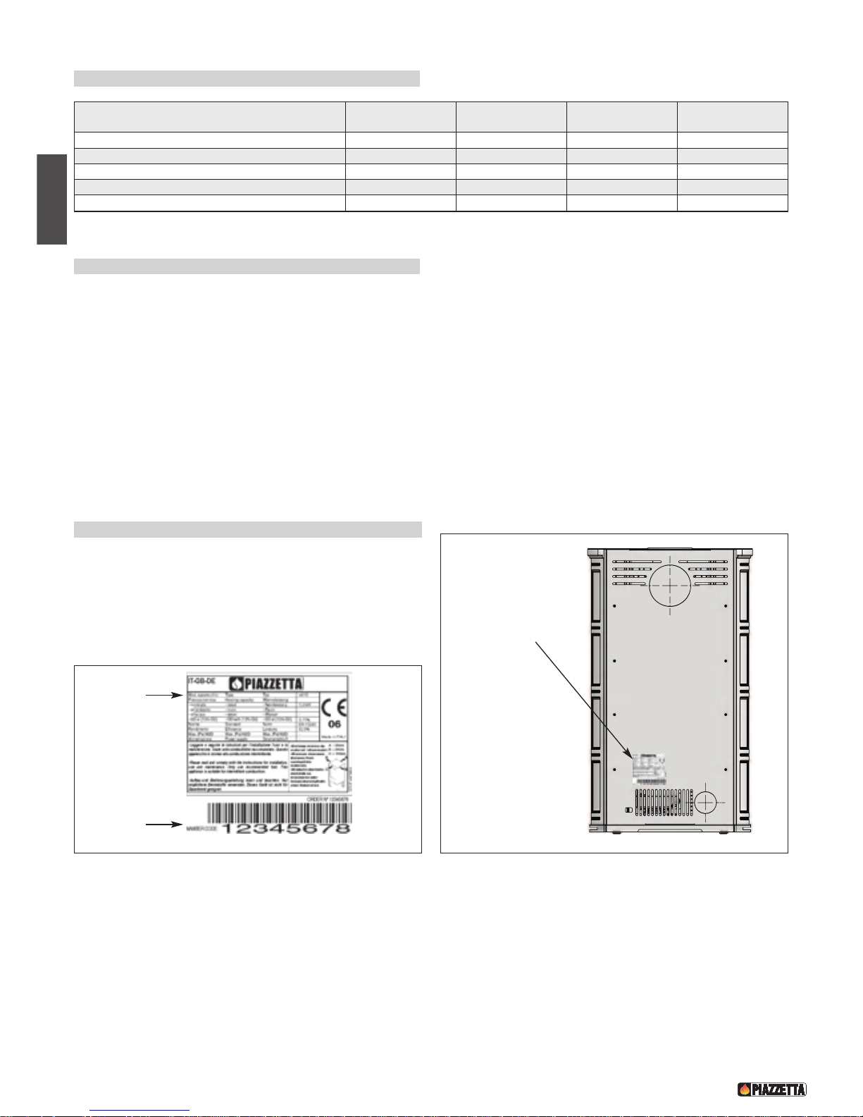
2.2 Accessories
2.3 Features
Fuel . . . . . . . . . . . . . . . . . . . . . . . . . . . . . . . . . . . . . . . . . . . . . . . . . . . . . wood
Stove . . . . . . . . . . . . . . . . . . . . . . . . . . . . . . . . . . . . . . . . . . . . . . . . . . . . enamelled steel
Fireplace . . . . . . . . . . . . . . . . . . . . . . . . . . . . . . . . . . . . . . . . . . . . . . . . . Aluker
®
Grate with fireguard . . . . . . . . . . . . . . . . . . . . . . . . . . . . . . . . . . . . . . . . cast-iron
Primary air damper . . . . . . . . . . . . . . . . . . . . . . . . . . . . . . . . . . . . . . . . . adjustable
Secondary air damper . . . . . . . . . . . . . . . . . . . . . . . . . . . . . . . . . . . . . . . adjustable
Ash tray . . . . . . . . . . . . . . . . . . . . . . . . . . . . . . . . . . . . . . . . . . . . . . . . . . removable
Ceramic glass heat resistant up to 750°C . . . . . . . . . . . . . . . . . . . . . . . . -
Handle . . . . . . . . . . . . . . . . . . . . . . . . . . . . . . . . . . . . . . . . . . . . . . . . . . . steel with silicone grip
Oven . . . . . . . . . . . . . . . . . . . . . . . . . . . . . . . . . . . . . . . . . . . . . . . . . . . . stainless steel (only for stove e911)
Smoke outlet . . . . . . . . . . . . . . . . . . . . . . . . . . . . . . . . . . . . . . . . . . . . . top and rear (top flue gas outlet only in stove e911)
44
English
2.4 Product identification data - Fig 28-29
The rating plate gives the data and ratings of the appliance.
If the rating plate is missing, has been removed or tampered with,
any installation and maintenance operations are made difficult due
to lack of product identification.
In the event of damage, please ask the Piazzetta after-sales service
centre for a copy.
PRODUCTION
IDENTIFICATION
AND RATING PLATE
Fig. 29
DT2030778-01
Product name
Serial number
DT2030070-01
Fig. 28
Description e911 e912
e915
e917 - e918
e920
e922 - e923
Right-hand glove In kit In kit In kit In kit
Silicone paint spray can In kit In kit In kit In kit
Pipes and elbows for connection to the flue Accessory Accessory Accessory Accessory
Rear outlet connection D.150 mm - Accessory Accessory Accessory
Multifuoco 2003 ventilation kit Accessory Accessory - Accessory
Page 45
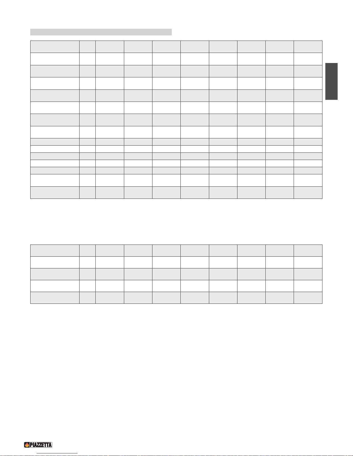
English
45
2.5 Technical data
These data are obtained using beech wood with moisture content below 20% and with intervals between stoking-up of approximately one hour.
Use of this appliance is intermittent.
Technical data with closed grate for flue calculations
U.M. e911 e912 e915 e917 e918 e920 e922 e923
Rated heat output
kW 7 8 5 5 5 8 8 8
Consumption at rated
heat output
kg/h 2,1 2,6 1,7 1,7 1,7 2,6 2,6 2,6
Thermal efficiency
% 80,2 75,5 82,5 82,5 82,5 75,5 75,5 75,5
CO content (with 13% O2)
% 0,11 0,10 0,11 0,11 0,11 0,10 0,10 0,10
Certified in according to
norm
- EN 13240 EN 13240 EN 13240 EN 13240 EN 13240 EN 13240 EN 13240 EN 13240
Homologation number
- CS-06-146 CS-06-145 CS-06-144 CS-06-144 CS-06-144 CS-06-145 CS-06-145 CS-06-145
VKF AEAI registration no.
- - - Z 13000 - - Z 13000 - -
Flue diameter cm Ø15 Ø15 Ø15 Ø15 Ø15 Ø15 Ø15 Ø15
Firebox opening (WxH) cm 29x40 29x40 25x35 25x35 25x35 29x40 29x40 29x40
Chamber sizes (LxDxH) cm 31x34 h26,5 - - - - - - Firebed cm
2
1130 1130 875 875 875 1130 1130 1130
Weight kg ca. - - - - - - - -
Weight with majolica kg ca. 230 190 136 151 146 163 181 183
Fresh air intake with
minimum useful section
cm
2
100 100 100 100 100 100 100 100
U.M. e911 e912 e915 e917 e918 e920 e922 e923
Nominal output kW 7 8 5 5 5 8 8 8
Mass of smoke g/s 6 9 4 4 4 9 9 9
Average temp. Smoke in
gas discharge pipe
°C 260 340 300 300 300 340 340 300
Minimum draught Pa 10 12 10 10 10 12 12 12
Page 46
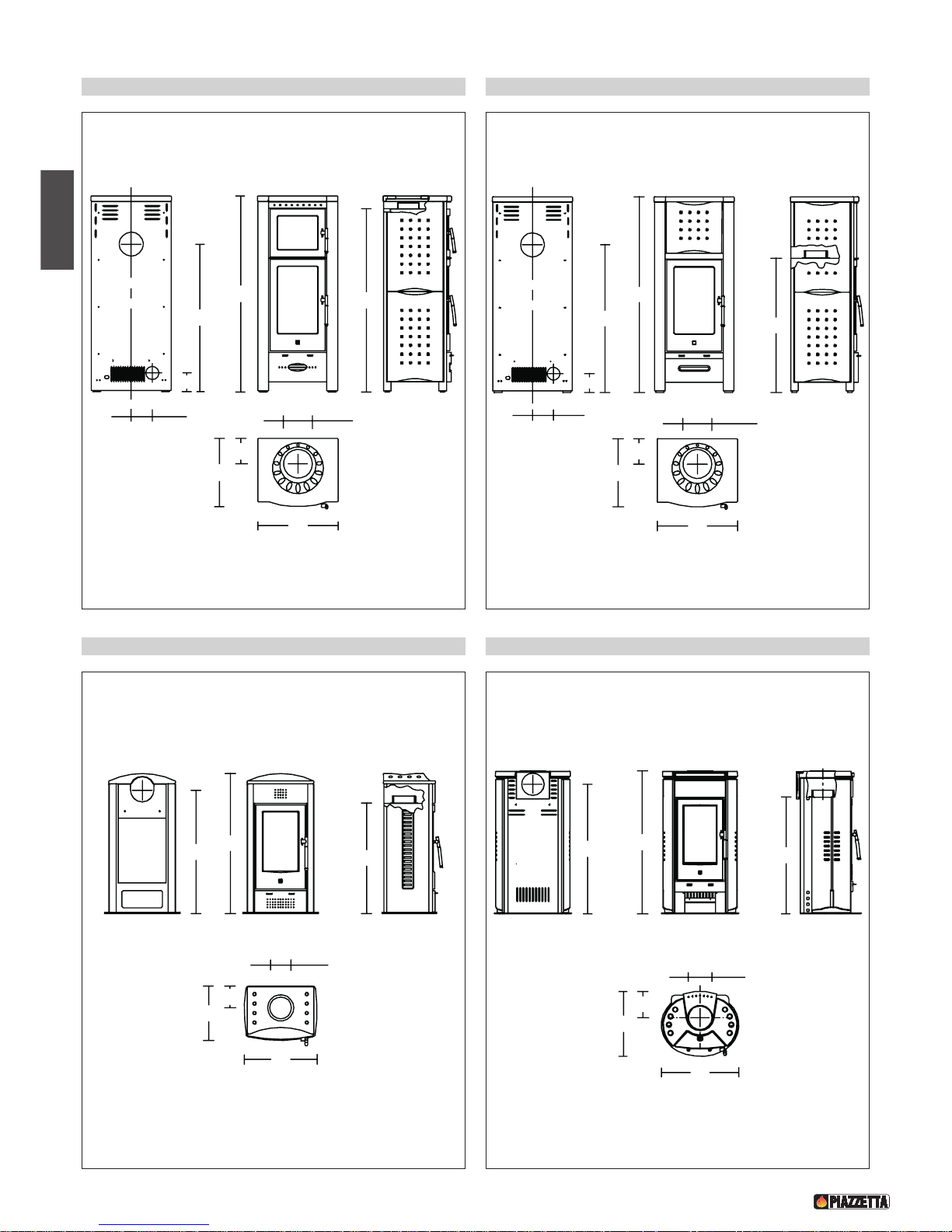
46
English
2.6 Dimension e911 2.7 Dimension e912
13 5
126,5
102
47
55
13
Ø15
14,5
17,5
102
47
55
13
Ø15
93
135
14,5
17 ,5
DT1020017-00DT1020016-00
Ø
14 ,5
50
96
76 ,5
15
37
85
DT1020095-00
46
55
10 2
92 ,5
19
84 ,2
Ø15
DT1020232-00
2.8 Dimension e915 2.9 Dimension e917
Page 47
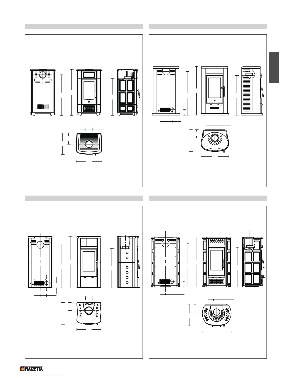
English
47
2.10 Dimension e918 2.11 Dimension e920
26
10 7
60
50
95
Ø1 5
86
Ø
11 3,5
93
10 2
65
15
19,5
13
51
14 ,5
DT1020015-00DT1020270-00
56
18 ,5
12 0
100, 5
11,5
14,5
91, 5
51
Ø15
DT1020231-00
10 2
117
17
49
68
93
Ø15
14, 5
13
DT1020271-00
2.12 Dimension e922 2.13 Dimension e923
Page 48
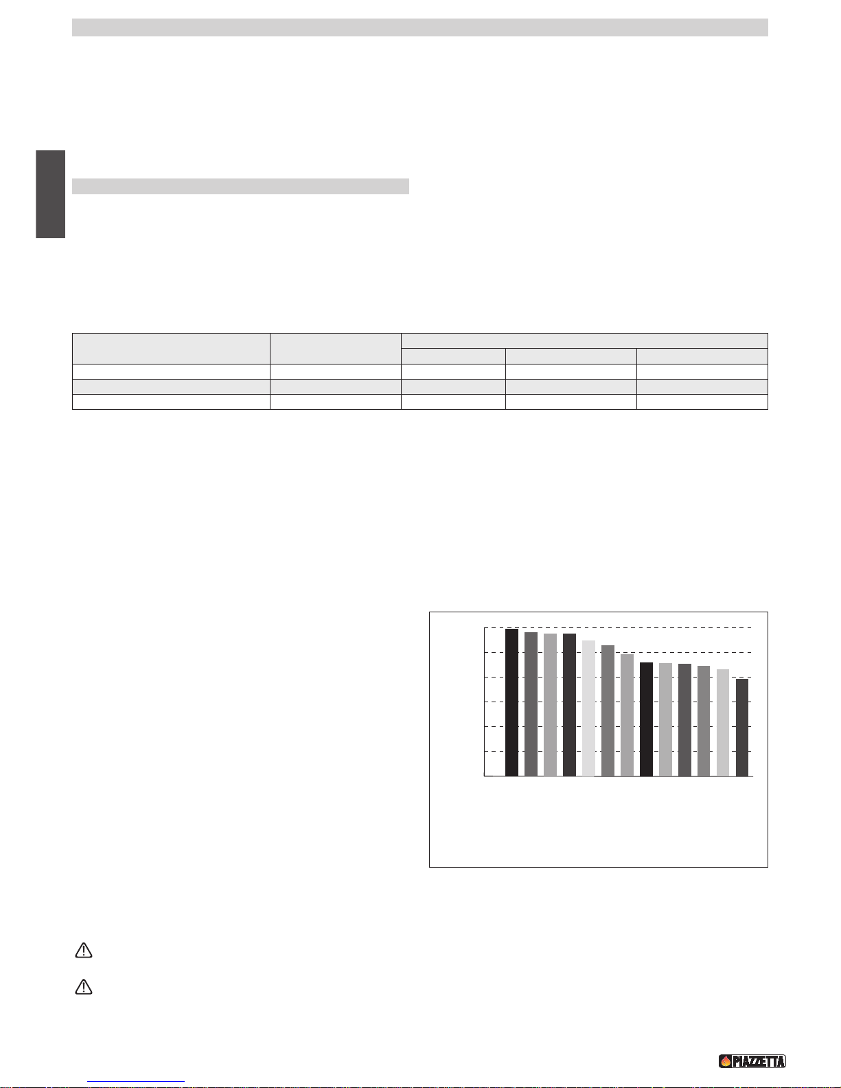
48
English
3.0 USE
DT2010453-00
3.1 Fuel - Fig. 30
Use well-seasoned and dry wood with less than 20% moisture content.
Wood that is ready to burn must have been dried in the open air sheltered from rain or snow for at least 2 years after having been cut.
The lower the moisture content of the wood the higher its heating power. Freshly cut wood has 50% less heat value than dry wood.
Burning wood that is too wet means wasting most of the calories for evaporation of the water contained in it and, in particular, the walls
of the combustion chamber and the flue become fouled and encrusted thereby affecting efficiency.
The table below shows how the heating power decreases as the moisture content increases.
* Approximate values.
It is a good rule to purchase timber during the summer (June-July), since woods are cut down mostly in the autumn and you can therefore
be sure that the timber has already been seasoned for approximately 1 year.
Firewood can be classified in two qualities: “good” and “mediocre or poor".
This classification is according to the heat yield of the wood, the longest flame time it provides, its composition and density.
Good fuels
- Recommended timber comes from the family of broadleaf hardwoods: beech, hornbeam, oak, false acacia, ash, birch, maple, elm.
- All low-resin and close-grained woods (that is hard and heavy
timber) are most suitable, since they provide the stove with a
steady, continuous flame.
Mediocre or poor fuels
- Timber that is not recommended comes from the family of
conifers, willow, poplar and alder. These light soft woods are
resinous and therefore create more soot, few embers and
incandescent sparks, while requiring more frequent cleaning of the
flue and the fireplace.
- Another characteristic of softwood is that it gives a lively but short-
lived flame and the consumption is higher for the same heat
output.
Unsuitable fuels
- Never use wet wood, tarred wood or pellets.
- It is also best not to use: refuse (rubbish), waste paper; paper briquettes; plywood or chipboard; fibreboard; packaging materials; painted
wood or wood coated with synthetic material, plastic laminates, cardboard or milk cartons.
Under no circumstances use liquid fuel of any kind whatsoever.
All these materials or similar ones could be hazardous for the user, damage the fireplace, the flue connection and the flue, and,
last but not least, pollute the environment.
• Certain basic facts can be all-important for best performance and
getting the most out of your appliance. Please find below some
basic information intended to be of use with regard to the choice
of firewood, the adjustment of the dampers and proper operation
of the appliance.
• During operation, some parts of the appliance (door, handle,
dampers, surround) can reach high temperatures. Therefore
exercise great care and take all necessary precautions.
• When you need to add wood to the fireplace or to adjust the air
flow, use the glove or the hand protector provided.
DT2010055-00
Moisture content (W) Seasoning time
HEATING POWER OF THE WOOD (Beech)*
kWh/kg Kcal/kg kWh/dm
3
20 after 2 years 4 3400 2.9
30 after 1 year 3.4 2900 2.8
40 after 6 months 2.8 2410 2.7
0
0,5
1,0
1,5
2,0
2,5
3,0
Hea ting Power ( KW h/ dm
3
w= 20%)
SPRUCE
SIL
VER FIR
WILLOW
ALDER
POPLAR
PINE
LARCH
BIRCH
BEECH
ASH
O
A
K
LOCUST
WHITE BEECH
Approximate value referred to ONE cubic decimetre of evenly shaped pieces of
wood with approx. 20% moisture content.
DT2010053-00
Page 49
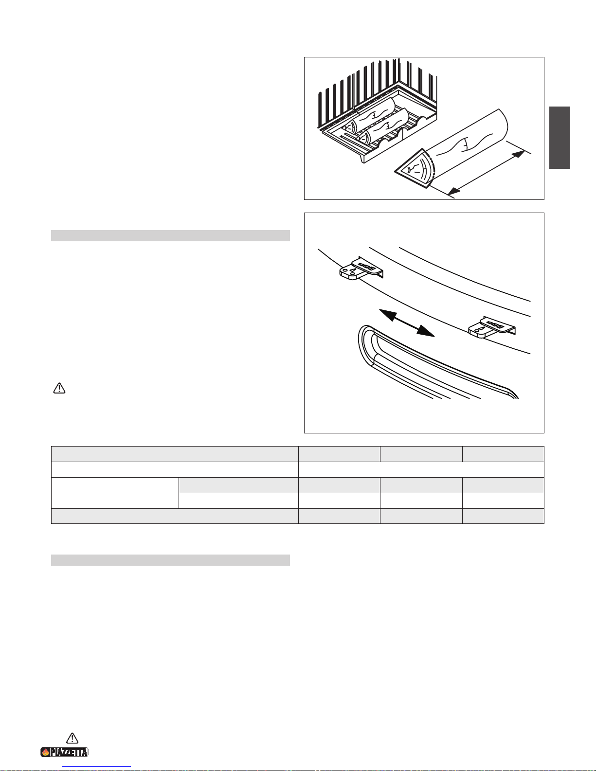
English
49
Log size
The size of the wood logs can also affect the efficiency of the
product.
- It is essential for the wood to be arranged on the grate on top of a
layer of embers.
- The logs must not touch the aluker or the glass window nor must
they be put on top of each other. Place the wood as shown in the
figure30.
- We therefore recommend using logs of the following size:
perimeter approx. 30/35 cm;
length approx. 20–25–30 cm according to the type of hearth.
3.2 Adjusting the combustion air - Fig. 31
The nominal heat output is determined with the air dampers. Take
note of the positions given in the table below, according to the fuels
being used.
The positions given below naturally refer to nominal output. Since
the output also depends on atmospheric and climatic conditions and
therefore on the draught, the most suitable position will be learned
with experience.
Adjustment can be made as shown in the figure to the side.
an excessive amount of fuel and excessive opening of the air
dampers compared to table values, leads to an increase in
heat of the appliance, decrease in efficiency and increase in
the consumption of wood.
(*) Data measured in laboratory qualified for certification.
3.3 Lighting for the first time
There are two important stages when lighting the appliance for the first time: the operating test and start-up.
1. Operating test
- Before carrying out the operating test, check that everything has been installed correctly (see section GENERAL RULES).
- Start with the lighting stage (see paragraph LIGHTING).
- The first load should be reduced by 50% of the normal recommended amount.
Should smoke come out:
• do not open the door of the stove;
• close the combustion air dampers (MINIMUM position) only on appliances with combustion air damper;
• let the fire go out slowly;
• air the room before staying in it;
• check the cause of malfunctioning.
Do not extinguish the fire with water as this could damage the grate
MIN
MAX
DT2030755-00
Fig. 31
Secondary air
Primary air
Adjustment and quantity of material to be burned for nominal output: e911 e915-e917-e918 e912-e920-e922-e923
Material to be burned Wood
Damper position
Primary primary air closed primary air closed primary air half open
Secondary secondary air half open secondary air open secondary air open
Maximum quantity of fuel to be burned kg 2,10 kg 1,70 kg 2,60
Peri meter
Len
ght
DT2030063-00
Fig. 30
Page 50
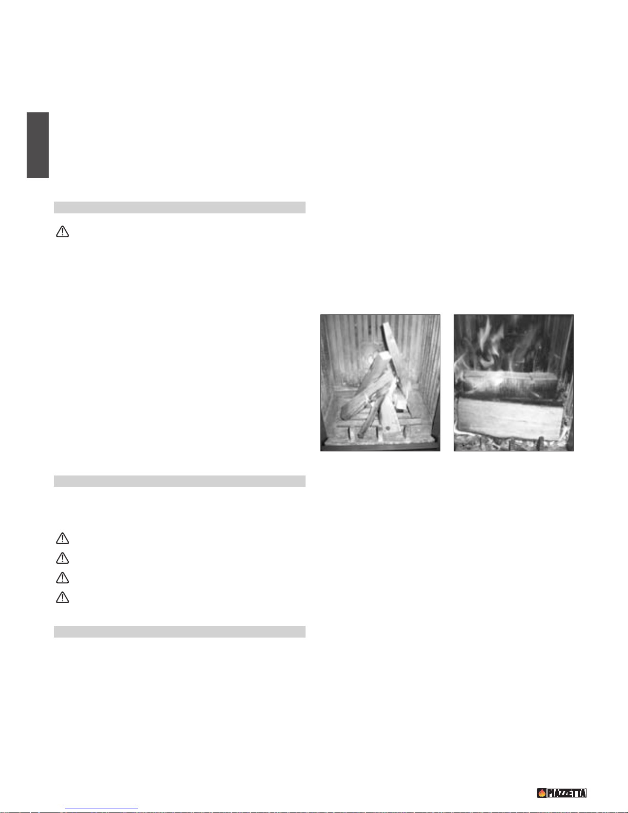
50
English
2. Start-up
- During this first time of operation it is recommended to use the appliance at minimum capacity, stoking the grate for at least the first
day with only 50% of the logs usually indicated as normal.
- Keep the air dampers in the operating position (except for lighting), see paragraph “Combustion air regulation”.
- This stage allows all the parts to settle down and fumes caused by paints/varnishes, greases or oily liquids used in manufacture to
disappear.
- Air the room well in this initial stage.
- This procedure must be carried out with the forced ventilation system turned off.
After this, the appliance will no longer emit odours due to paint evaporation and must only be stoked up with the indicated nominal amounts.
3.4 Lighting - Fig. 32 - 33
Before lighting, remove the supplied accessories (see accessories paragraph) and flammable elements from the grate or from
the ash tray. If provided in the kit, it is very important to remove the paint spray can, which could explode.
When lighting the fire, the grate should be brought quickly to working temperature. If it is done slowly, condensation will inevitably form
and cause blackening of the grate and the glass.
Put the fuel into the grate according to the methods described below:
1. Put the dampers to the open position (MAXIMUM) (see
paragraph “Combustion air regulation”).
2. Place the material for kindling (paper, firelighter, etc.) in the
centre of the grate and add small pieces of soft wood (fir) in the
form of a pyramid. To light the soft wood quickly, open the door
by approx. two centimetres for 5–10 minutes. Figure 32
3. Once a bed of embers has formed proceed to fill with fuel fig. 33
and to adjust the dampers, referring to the table in the paragraph
“Combustion air adjustment”. Do not open the firebox during
operation.
3.5 Opening the door
The door must remain closed while the stove is alight, otherwise it could damage the inside of the stove.The door must be opened slowly,
holding it slightly ajar for a moment before opening it completely. Open the door when the flame has died down and certainly never when
the flame is very intense.
Always use the glove provided.
Ensure that the self-closing door does not bang shut, as this could break the glass.
The glove is not designed for picking up burning embers!!!
It is not dangerous if smoke comes out while the stove is stoked; just open the window for a while.
3.6 Night time operation at minimum
After normal operation during the day, the appliance may continue to operate for a few hours at night.
When stoking up the fire for the last time in the evening, ensure that the bed of embers is sufficient, put the wood in the grate and then
set the combustion air dampers to minimum. Night time operation of the stove at minimum depends on the type of wood (a very hard
wood is recommended), the flue draught and the weather.
The amount of wood to put on and the necessary adjustment of combustion air flow will be learned with experience (see the paragraph
“Combustion air dampers”).
The next morning, start up the fire at maximum to burn off any creosote formed during the night. Creosote deposits start to form when
the flue temperature falls to below 150 °C. To prevent this from happening it is important to try to maintain the grate of the appliance at
normal working temperature (rated heating efficiency phase) as long as possible.
Prolonged operation of the stove at minimum could require more frequent cleaning of the grate and the flue.
DT2030065-00
Fig. 33
DT2030064-00
Fig. 32
Page 51
English
51
3.7 Operation under adverse weather conditions
During the intermediate seasons with adverse weather conditions or when outdoor temperatures are higher, a sudden rise can cause
malfunctioning of the draught, thereby impeding proper smoke discharge. In this case the grate must be loaded with only a little wood
and the primary air damper be set fully open so that the wood burns faster and thereby stabilises the draught.
3.8 Overheating and Extinguishing
In the event of overheating or if some appliance parts or the flue turn red:
- immediately stop the supply of fuel;
- do not open the stove door;
- close the air dampers (MINIMUM position);
The fire will go out due to lack of air.
When the appliance has cooled down, find the cause of the problem and if necessary call in specialised personnel.
In the event of fire, extinguish with a fire extinguisher.
Do not extinguish the fire with water.
Air the room well before using it again in order to get rid of any smoke and combustion gases.
3.9 Humidifier (only in stove e917 – e918 – e922 – e923)
It's possible to humidify the room where the stove is installed, using the “500cc sprayer phial” pour water in the tank through the hole
on the cooking surface. Pay careful attention not to fill the reservoir beyond the limit fixed on the reservoir, indicated with the symbol
“MAX”, otherwise water overflows from the humidifier.
3.10 Using the oven (only in stove e911)
A cooking guide is not provided since experience is the best teacher, which, added to personal imagination and skill, will help you to create
excellent dishes. The thermometer provided in the kit will undoubtedly help by showing the right moment for putting in the food, while
the large ceramic glass door allows you to see how cooking is progressing.
On the other hand a few tips will surely be useful:
- bring the product up to temperature starting with small pieces of wood and only gradually adding larger pieces. Never exceed the
recommended load;
- do not put food into the oven as soon as the required temperature has been reached since it is highly probable that the temperature will
continue to rise with the risk of ruining the food in the oven;
-
at a certain point the temperature will start to drop. When it remains stable for a few minutes, this is the best time to put food into the oven;
- it is inadvisable to exceed 250°C as this is more than sufficient for every type of cooking. Only in the initial stages may a peak of 280-
300°C be reached. Higher temperatures are not only unsuitable for correct cooking, but could make the structures expand too much;
- once the food has been put into the oven, just keep the temperature constant by a calibrated stoking up with wood and suitable
adjustment of the air dampers. Only experience will teach you the best conditions for cooking a certain food, the quantity of wood to
burn in a given time and the position of the dampers, remembering that everything also depends on external factors such as the draught
and the weather;
-
remember that the thinner the food to be cooked, the less time and more heat are necessary; for example a chicken requires a long cooking
time (approx. 3 hours) at low heat (150-180°C) while a pizza cooks quickly (approx. 10 minutes) at higher temperatures (220-230°C);
- if the flue pipe creates excessive draught or the wood in any case burns fiercely developing excessive heat with difficulty in controlling
combustion, the heat is not correctly transferred to the oven but passes directly into the flue; it is advisable to add fuel as recommended
and adjust the air dampers. Only if strictly necessary should a pipe with damper be installed;
- for cooking at low heat, shut off the primary air, keeping the secondary damper approximately half or a quarter open and keep any smoke
damper partly open to ensure an adequate draught;
- successful cooking also depends on the wood that is used: hard wood (e.g. beech) and large logs burn more slowly and last longer,
while small logs and softer wood develop a more intense but short-lived flame;
- when taking the food out of the oven to check the state of cooking, close the door to avoid the temperature dropping in the oven.
A change in colour of the oven is a natural feature of steel subjected to sudden changes in temperature. This does not affect the
quality of the product.
Page 52
52
English
4.0 MAINTENANCE
4.1 Periodic control
Check for any formation of creosote in the pipes connecting to the flue and inside the flue during the seasons when the appliance is in
operation, inspecting them at least once every two months.
The combustion of the wood (especially if moisture content is higher than 30%) produces pitch and other organic vapours that give rise
to creosote. The formation of creosote causes fouling, which obstructs the flue and the passage of smoke.
“Creosote” is inflammable and can catch fire, causing serious damage to both the flue and to the structure of the dwelling.
Only use recommended fuels (see “Fuels” paragraph).
If creosote has accumulated, it must be removed to reduce the risk of fire and to improve heat exchange.
The following must be free from obstruction and inspected at least once every two months:
- the flueways (connection to the flue, flue pipe, chimney stack);
- the fresh air intake;
- the appliance hearth (correct position of the plates, the ash tray, the grate and grid, deflectors, smoke dampers, etc);
- the ventilation system (apertures, air ducts, grilles) if installed.
Check that the automatic door closing system and the air dampers are in proper working order.
Maintenance of all the above heating system must be carried out at least once a year before the season when it will be used.
We also recommend periodically checking the whole heating system during the period of operation until the time when it will
not be used for several months.
4.2 Cleaning the ceramic cladding
The ceramic cladding must first be cleaned with a soft dry cloth before using any detergent (even mild detergent).
Products are available on the market which are specially adapted for cleaning ceramics, or concentrated for cleaning porcelain. These will
remove oil, ink, coffee and wine stains.
Never soak the ceramic or clean it with cold water when it is still hot - The thermal shock could cause it to crack.
4.3 Cleaning the steel parts
The steel sections of the cladding should be cleaned with a soft, dry cloth before applying any detergents. Afterwards it is recommended
that you use a degreasing agent such as acetone or vinegar diluted in water.
4.4 Cleaning the painted metal parts
When cleaning the parts of the product in painted metal use a soft cloth moistened with water.
Never clean metallic parts using alcohol, solvents, petroleum-based agents, acetones or other degreasing or abrasive substances.
In the event of such substances being used the manufacturer declines all responsibility for damage caused.
Discolouration of metallic parts may be the result of improper use.
4.5 Cleaning the glass (DAILY)
The glass should be cleaned when cold using ammonia-based degreasing agents and not corrosive substances such as solvents.
If the appliance is very slow to heat up in the ignition phase due to fuel that isn’t completely dry, this is likely to cause a build-up of tar
on the glass. This will eventually burn off when the secondary air supply is open (if the appliance is equipped accordingly) or when the
appliance is functioning at full capacity. If the tar is left to build up over a long period it will require more effort to remove it. We therefore
recommend that the glass be cleaned daily before lighting the stove.
IN CASE OF BREAKAGE: Every one of our hearths comes with a door fitted with a 4 mm thick glass panel resistant to a thermal shock of
750°C. This can only be broken by a heavy impact, such as banging the door too hard.
In case of breakage replace with original Gruppo Piazzetta S.p.A parts only.
Do not use any material that could scratch or spoil the glass, as scratches may develop into cracks or breaks.
• All maintenance work (cleaning, replacing parts, etc…) should be carried out when the stove has been extinguished and allowed to cool.
Furthermore, do not in any circumstances use abrasive substances.
DT2010057-00
DT2010463-00
Page 53
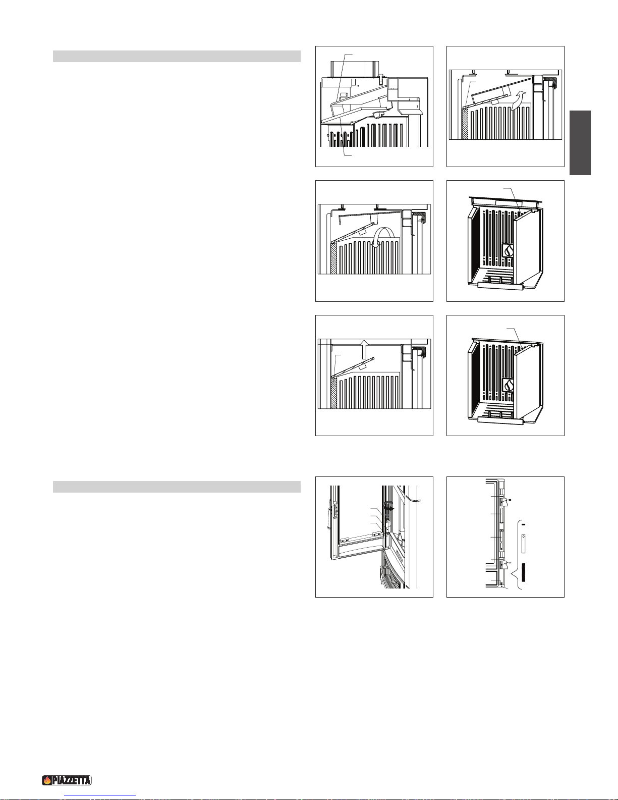
English
53
4.6 Removal of smoke deflectors
When cleaning the stove, remember to remove the two smoke
deflectors as well (in the e911 model a single deflector is present).
It is recommended that this operation is carried out by two people,
as follows:
- lift up the two deflectors at the front, pivoting them on the back
panel;
- holding the back panel firm with one hand, remove the Aluker side
panels one at a time, still supporting the smoke deflectors; extract
these from the fire keeping them at an angle;
- carefully lower the smoke deflectors towards the floor of the fire
and remove them carefully one at a time, turning them until you
find the correct angle to get them out through the mouth of the
stove.
- Then clean and remount them, working in the reverse order.
4.7 Door assembly
To remove the door it is merely necessary to slide the pins out of the
hinges after having released the screws shown in the drawing.
The spring must be tensioned when remounting the door in order to
guarantee automatic closing:
- insert the pin into the upper hinge and fasten it with the grub screw;
- insert the spring, bush and related tube in the space in the lower
part of the door;
- slide in the lower hinge pin and turn it until it slots onto the spring
(this can be seen by looking through the hole in the tube);
- holding the pin down and using the key supplied, turn it as shown in the photograph until it gives, then hold it with the grub screw;
repeat the operation another two or three times;
- Check carefully that the automatic closing of the door is working properly and if not, turn the spring further.
DT2030763-00
Fig. 34
DT2030764-00
Fig. 35
DT2030765-00
Fig. 36
DT2030766-00
Fig. 37
DT2030767-00
Fig. 38 - e911
DT2030768-00
Fig. 39 - e911
DT2030769-00
Fig. 40
DT2030770-00
Fig. 41
Upper smoke deflector
Lower smoke deflector
Back panel
Side panel
Side panel
Back panel
Pin
Grub Screw
Tube with
spring
Washer
Washer
Pin
Upper hinge
pin
Lower hinge
pin
Grub Screw
Bush
Tube
Spring
Grub Screw
Grub Screw
Page 54
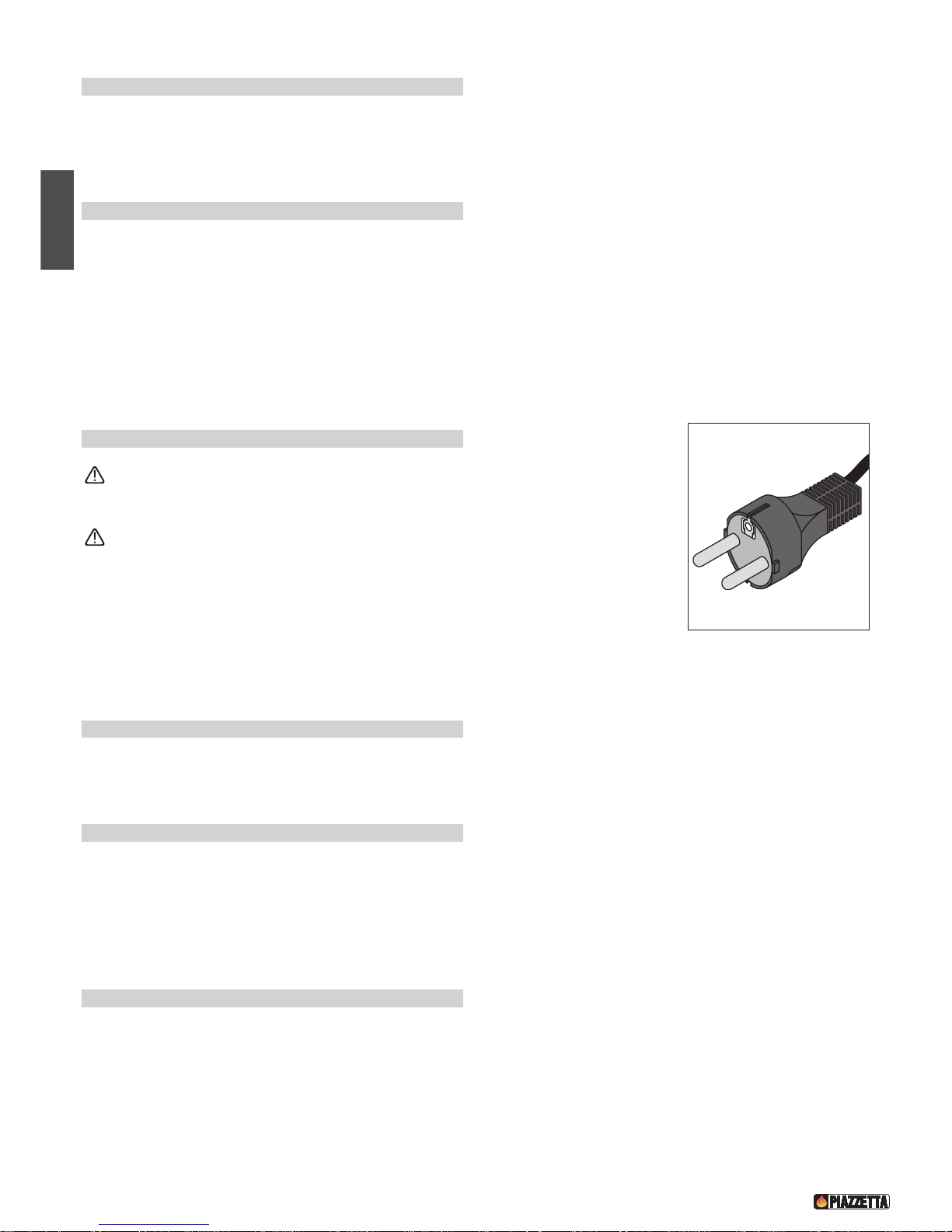
54
English
4.8 Cleaning the grate and the ash tray (EVERY DAY)
The grate and the ash tray must be cleaned daily. Using the grate for a whole day contributes to the accumulation of ash or residual
combustion products.
If cleaning is not done regularly there will be an excess of residues, which will affect appliance efficiency.
The ash tray also needs emptying regularly, because if it fills up and obstructs the grate grid it will cause appliance malfunction.
4.9 Cleaning Aluker
®
The interior of the unit has been constructed from an innovative material called “Aluker®”.
Aluker®is based on substances that are completely non-toxic and is heat-resistant up to 1400°C.
In spite of its considerable strength it is not recommended that you throw large pieces of wood forcefully
against the bricks.
Aluker®darkens when the stove is first lit but returns to its natural colour gradually as the bricks warm up.
Some advice for optimum use of Aluker
®
bricks:
- Don’t use water to put out the fire - leave the bricks to cool by themselves;
- Don’t scratch Aluker
®
bricks with metal objects;
To clean Aluker
®
bricks use an ordinary brush.
4.10 Cleaning the fan (ONCE A YEAR) - Fig 34
all cleaning and maintenance operations must be carried out after DISCONNECTION OF THE
POWER
Pursuant to current regulations on the safety of electrical equipment, you must contact a
Piazzetta After-Sales Service Centre or a qualified electrician for all and any work connected
with installation, maintenance or servicing that involves access to electrical parts.
Dust can accumulate in the ventilation kit and in particular in the holes of the protective cover of the fan,
the grilles and the fan blade, which should therefore be cleaned once a year. Use a vacuum cleaner or
compressed air, being careful with the electrical parts.
The ventilation kit must be disassembled for proper cleaning. Follow the installation procedure in the reverse order (see the instructions
enclosed in the kit).
4.11 Seal control
Proper tightness of the door seal is essential for optimal product performance. It is therefore recommended that the seals be checked
periodically or after a long period of use for signs of wear or damage. If necessary replace them using Gruppo Piazzetta S.p.A. original
spare parts.
4.12 Shutting down
Before any long period during which the stove will be inactive we recommend that you carry out a thorough cleaning, thereby avoiding
encrustations and oxidations which will be difficult to clean later. We also recommend that as a preventative measure you carry out a
general checkup as outlined in the paragraph headed “Periodic checks”.
After a period of inactivity problems relating to the expansion of parts or the release of odorous gases may arise. We therefore recommend
that upon restarting the unit you do not immediately run it at full power. Nor should you activate the ventilation system until the odorous
gases have dispersed. This problem can be dealt with by simply airing the room.
4.13 Disposal of ashes
The ashes should be placed in a metal container with a sealed cover. Until the cinders have been completely extinguished the sealed
container should be placed on a non-combustible surface a safe distance from combustible materials.
Only when they have been extinguished can the ashes be thrown in along with organic refuse, assuming that nails or other non-organic
material are not present.
Ashes from natural (non-treated) wood deriving from combustion in stoves or open fires is composed principally of calcium, silicon,
potassium and magnesium oxides. Because of this the ashes can be used as fertiliser for plants or in the garden, not exceeding 2.6 kg
per 10m2annually.
DT2030069-00
Fig. 34
Page 55
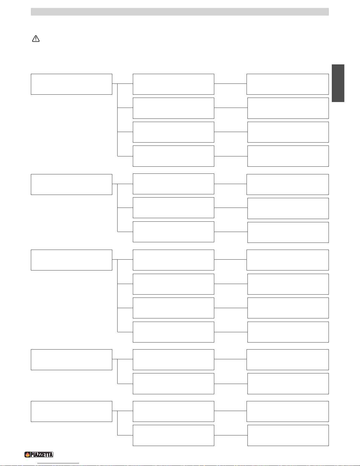
English
55
5.0 TROUBLESHOOTING
DT2010069-00
Qualified personnel must carry out all operations in safety when the appliance is cold and disconnected from the power supply.
Problem Cause Remedy
The window becomes
excessively dirty
Lack of draught Check the smoke/gas discharge pipe
Wet wood Use dry wood
Use of mediocre or poor class fuels
Change the type of fuel
(See “Fuels” paragraph)
Not enough combustion air Open the air dampers further
Condensation forms
Section of flue too large
Reduce the section by inserting a
well insulated pipe with suitable
section inside the flue
Flue not adequately insulated
Clad the flue with hollow tiles or
other insulating materials
Slow combustion and therefore low
smoke temperature
Burn smaller and dry logs.
Open the primary air damper further
Smoke comes out of the fireplace in
adverse weather conditions
Chimney stack has no down-draught
cowl
Replace the chimney stack with one
that has a down-draught cowl
Flue not suitably insulated
Clad the flue with hollow tiles or
other insulating materials
Difficulty in lighting Closed air damper
Put the combustion air (intake)
dampers to maximum position
Logs too large Use smaller logs
Wood too wet Burn drier wood
Lack of draught Check the smoke/gas discharge pipe
Smoke comes out upon opening the
door
Door opened too fast
Keep the door just ajar for a few
seconds before fully opening
There are still flames
Only open the door when just embers
remain in the grate
Page 56
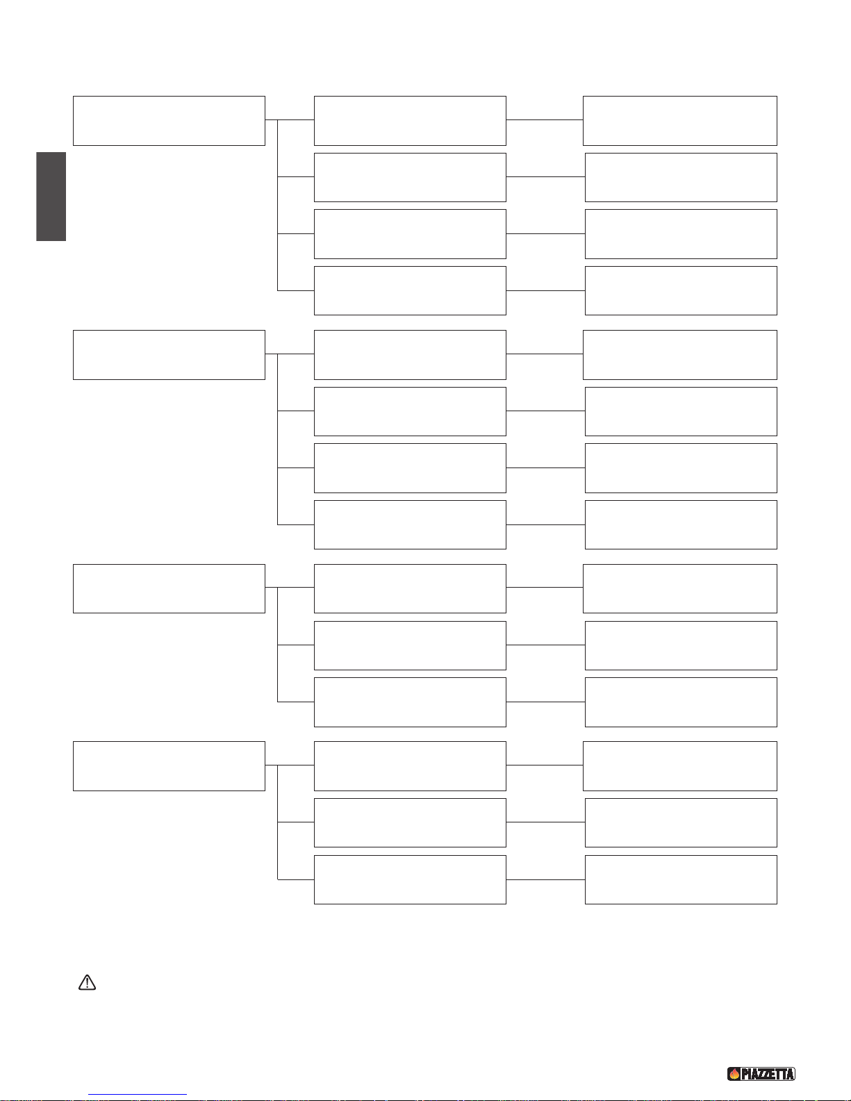
56
English
(*) Pursuant to current regulations on the safety of electrical equipment, you must contact a Piazzetta After-Sales Service
Centre or a qualified electrician for all and any work connected with installation, maintenance or servicing that involves access
to electrical parts.
Problem Cause Remedy
The grate does not warm
Quantity of wood less than necessary
for nominal efficiency
Use the quantity of wood indicated in
the instructions (See “Adjusting the
combustion air” paragraph)
Undersized grate for the environment
to be heated
Integrate with another product
Inadequate insulation for the
environment in which the fireplace is
installed
Insulate well with suitable materials
Oversized fresh air intake Decrease the intake section
Too little and only lukewarm air flows
from the outlets
Pipework not insulated Suitably insulate
Pipework too long or with too many
bends
Change the path, complying with the
ventilation kit instruction booklet
Too many branches Change the path
Environment too large for capacity of
the fan and power of the product
Heat fewer rooms or use the stove as
a supplementary source of heat
The fan does not work (*) Incorrect connection to power supply
Correct the connection according to
the assembly diagram
Electronic regulator damaged Replace the regulator
Power failure Power the appliance
Noisy fan (*) Presence of dust or similar in the fan Clean the fan
Vibrations Check fan position
Worn rotating parts
Maintain or replace worn parts
Replace the fan
Page 57
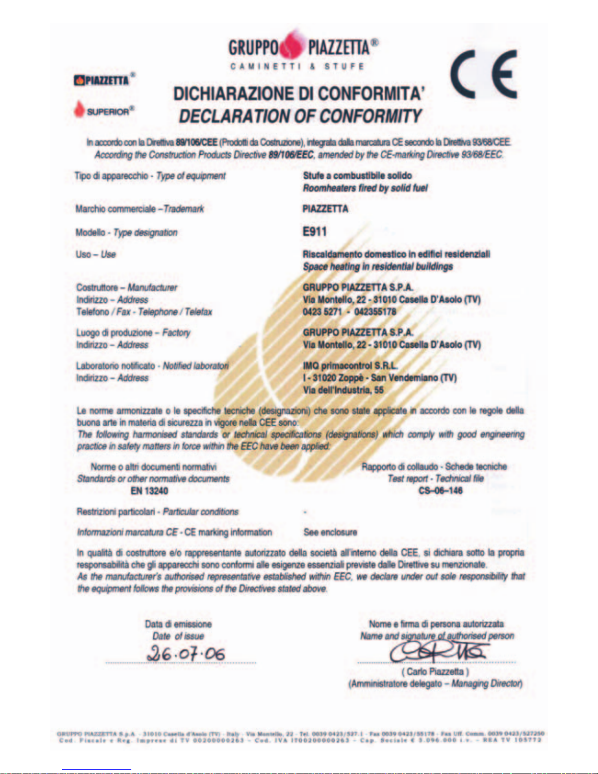
COPIA
Page 58
COPIA
Page 59
COPIA
Page 60

www.miotto.it
Gruppo Piazzetta S.p.A. Technical Department - cod. H07020320 / DT2000212 - Rev. 01-(05/2007)
Via Montello, 22
I - 31011 Casella d’Asolo (TV) Italia
Tel. +39.04235271 - Fax +39.042355178
http://www.piazzetta.it
e-mail:[email protected]
 Loading...