

Page 1
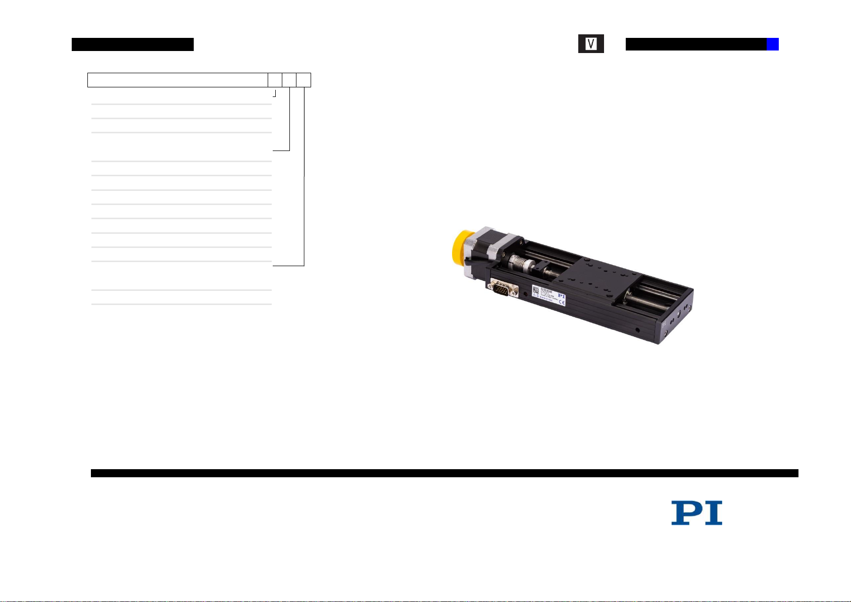
User Manual
VT-80 Translation Stage 1
Order no.
6230-9-
DC
1
SM
2
25 mm (xy mounted at PI)
1
50 mm
2
75 mm
3
100 mm
4
150 mm
5
200 mm
6
300 mm
8
Single axis
0
25 mm xy mounted
1
VT-80 Translation Stage
Order no. 6230-9-
User Manual
Version: 01.005 Date: 19.07.2019
Page 2

2 VT-80 Translation Stage
© 2019 PI GmbH, Eschbach, Germany. The text, photographs and drawings in this manual are protected by copyright. With regard thereto, PI GmbH retains all rights. The use
of any text, images and drawings is permitted only in part and only when indicating the source.
Subject to change without notice. This manual is superseded by any new release. The respective current revision is available for download on our website (http://www.pi.de ).
File name: MAN_VT-80_9_EN.DOCX.pdf Document-ID:DOC-000261817
Page 3

VT-80 Translation Stage 3
www.pi.de // [email protected] // phone:+49(0)7634-50 57 0 // fax:+49(0)7634-50 57 393
CONTENTS
1. ABOUT THIS DOCUMENT
1.1 Objective and Target Group of this User Manual
1.2 Symbols and Typographic Conventions
1.3 Other Applicable Documents
2. SAFETY
2.1 Intended Use
2.2 General Safety Instructions
2.2.1 Organizational Measures
2.2.2 Measures during Installation
2.2.3 Measures during Start-Up
2.2.4 Measures during Operation
2.2.5 Measures during Maintenance
3. UNPACKING
4. PRODUCT DESCRIPTION
4.1 Features and Application Area
4.2 Model Overview
4.3 Product View
4.4 Safety Instructions
4.5 Scope of Delivery
4.6 Optional Accessories
4.7 Technical Features
4.7.1 Technical Features
4.7.2 Motors
4.7.3 Limit Switch
4.7.4 Connector
4.7.5 Technical Data
4.8 Ambient Conditions
5. INSTALLATION
5.1 General Notes on Installation
5.2 Mounting the Stage
5.3 Affixing the Load
6. START-UP
6.1 General Notes on Start-Up
7. MAINTENANCE
8. TROUBLESHOOTING
9. CUSTOMER SERVICE
10. OLD EQUIPMENT DISPOSAL
11. EU DECLARATION OF CONFORMITY
Page 4

4 VT-80 Translation Stage
NOTICE
Dangerous situation!
If not avoided, the dangerous situation will result in
death, injuries or damage to the equipment
-> Actions to take to avoid the situation
NOTICE
Information for easier handling, tricks, tips, etc.
1. ABOUT THIS DOCUMENT
All specifications in this user manual refer only to the standard products that
are included in the PI catalog. Any special features that are different, in
particular special requests from customers, are supplied with the user
manual as additional documentation in the form of "Technical Notes".
1.1 Objective and Target Group of this User Manual
• This user manual contains all information required for the intended use
of the VT-80.
• Basic knowledge on servo systems, motion control concepts and
applicable safety measures is assumed.
• The latest version of the user manual and answers to any questions can
be obtained from our customer service department (see chapter 9)
1.2 Symbols and Typographic Conventions
The symbols and typographic conventions used in this manual have the
following meanings:
1.3 Other Applicable Documents
All products and programs from PI miCos mentioned in this documentation
are described in separate user manuals.
The latest versions of the user manuals can be obtained from our customer
service department (see chapter 9).
2. SAFETY
2.1 Intended Use
The VT-80 is a laboratory device as defined by DIN EN 61010-1. It is
intended for indoor use and use in an environment which is free of dirt, oil,
and lubricants.
In accordance with its design, the VT-80 is intended for positioning,
adjusting and shifting of loads at various velocities. The VT-80 can be
mounted horizontally or vertically.
The intended use of the VT-80 is only possible in conjunction with suitable
electronics. The following options are available:
1. Drive electronics and controller with suitable software
2. Combination device with suitable software
• The electronics are not included in the scope of delivery of the VT-80.
• The electronics must provide the required voltages. To ensure proper
performance of the servo-control system, the electronics must be able to
read out and process the signals from reference and limit switches, and
from the incremental position encoder.
Page 5

VT-80 Translation Stage 5
www.pimicos.com // [email protected] // phone:+49(0)7634-50 57 0 // fax:+49(0)7634-50 57 393
2.2 General Safety Instructions
The VT-80 is built according to state-of-the-art technology and recognized
safety standards. Improper use of the VT-80 may result in personal injury
and/or damage to the VT-80.
1. Only use the VT-80 for its intended purpose, and only use it if it is in
good working order.
2. Read the user manual.
3. Immediately eliminate any faults and malfunctions that are likely to affect
safety.
The operator is responsible for the correct installation and operation of the
VT-80.
2.2.1 Organizational Measures
User Manual
• Always keep this user manual available when using the VT-80. If the
user manual is lost or damaged, contact our customer service
department (see chapter 9).
• Add all information from the manufacturer such as supplements or
technical notes to the user manual.
• Only use the device on the basis of the complete user manual. If your
user manual is incomplete and is therefore missing important
information, serious or fatal injury as well as damage to the equipment
can result.
• Only install and operate the VT-80 after you have read and understood
this user manual.
Personnel Qualification
The VT-80 may only be started up, operated, maintained and cleaned by
authorized and appropriately qualified personnel.
2.2.2 Measures during Installation
The VT-80 may be damaged by excessively long screws and wrongly
mounted parts.
• When mounting the VT-80, make sure that the mounting screws do not
interfere with the stage motion. The screw heads must not protrude from
the countersunk holes.
• Observe the depth of the mounting holes in the moving platform.
• Only use screws of the correct length for the respective mounting holes.
• Only mount the VT-80 and the loads on the mounting fixtures (holes)
intended for this purpose.
• The VT-80 heats up during operation. High temperatures can influence
your application.
• Install the VT-80 so that your application is not affected by the
dissipating heat.
• Cable extensions can affect the performance of the VT-80 and damage
the electronics.
• Only use genuine PI miCos parts to connect the VT-80 to the electronic
equipment.
• Do not use cable extensions. If you need longer cables, use cable
extensions from PI miCos.
• Avoid short circuiting the lines for motor voltages since this can damage
the electronics.
Page 6

6 VT-80 Translation Stage
2.2.3 Measures during Start-Up
• Do not put your VT-80 into operation until it is fully mounted and
connected.
Your system can be damaged by uncontrolled oscillation of the VT-80.
Noise generated during operation of the VT-80 is a typical sign of oscillation.
• Immediately switch off the servo-control system of the affected stage
axes.
• Check the settings of the servo-control parameters.
Moving parts attached to devices with motorized stages can accelerate
rapidly and generate high forces which can cause injury or damage to
equipment.
Unintentional motion of the stage is possible when it is connected to the
controller for the first time. Defective software or incorrect operation of the
software can also result in unintentional motions.
• Do not place any objects in areas where they can be caught by moving
parts.
Collision of a part in motion at the end of the travel range and high
accelerations can cause damage to or wear on the mechanical system.
• Ensure that the automatic limit switch halt is supported by the controller,
or that it is activated in the controller.
• Do not disable the evaluation of the limit switch signals by the controller.
• Check the function of the limit switches at about 10 % to 20 % of the
maximum velocity.
• In the event of a malfunction of the limit switches, stop motion
immediately.
• Ensure that the end of the travel range is approached at low velocity.
Set the control signal so that the moving part does not stop abruptly or try to
continue motion at the end of the travel range.
• Determine the maximum velocity for your application.
2.2.4 Measures during Operation
• If noise occurs during operation of the VT-80, check the settings of the
servo-control parameters of your controller.
The highest dynamic force and holding force is achieved at a control signal
input level of 100%; however, the motor/drive may overheat during
continuous operation.
• During continuous operation at room temperature, do not exceed 90 %
of the control signal level.
• For continuous operation at other temperatures, observe the maximum
permissible duty cycle in relation to the ambient temperature or contact
our customer service department for more information (see chapter 9).
2.2.5 Measures during Maintenance
The VT-80 is precision adjusted.
Do not loosen any sealed screws.
Dirt, oil, lubricants and condensation will render the motor/drive inoperable.
Keep the VT-80 free of dirt and condensation water.
Page 7

VT-80 Translation Stage 7
www.pimicos.com // [email protected] // phone:+49(0)7634-50 57 0 // fax:+49(0)7634-50 57 393
WARNING
Risk of suffocation for children. Keep the packaging foil
away from children.
Dispose of packaging materials according to
environmental regulations.
NOTICE
All specifications in this user manual refer only to the
standard products that are included in the PI-miCos
catalog. Any special features that are different, in particular
special requests from customers, are supplied with the
user manual as additional documentation in the form of
"Technical Notes".
Order no.
6230-9-
DC
1
SM
2
25 mm (xy mounted at PI)
1
50 mm
2
75 mm
3
100 mm
4
150 mm
5
200 mm
6
300 mm
8
Single axis
0
25 mm xy mounted
1
3. UNPACKING
1. Unpack the VT-80 with care.
2. Compare the contents with the items listed in the contract and the
packing list.
3. Inspect the contents for signs of damage. If there is any sign of damage
or missing parts, contact PI miCos immediately.
4. Keep all packaging materials in case the product needs to be returned.
4. PRODUCT DESCRIPTION
4.1 Features and Application Area
Our products are designed specifically for use in the laboratory.
4.2 Model Overview
Page 8
8 VT-80 Translation Stage
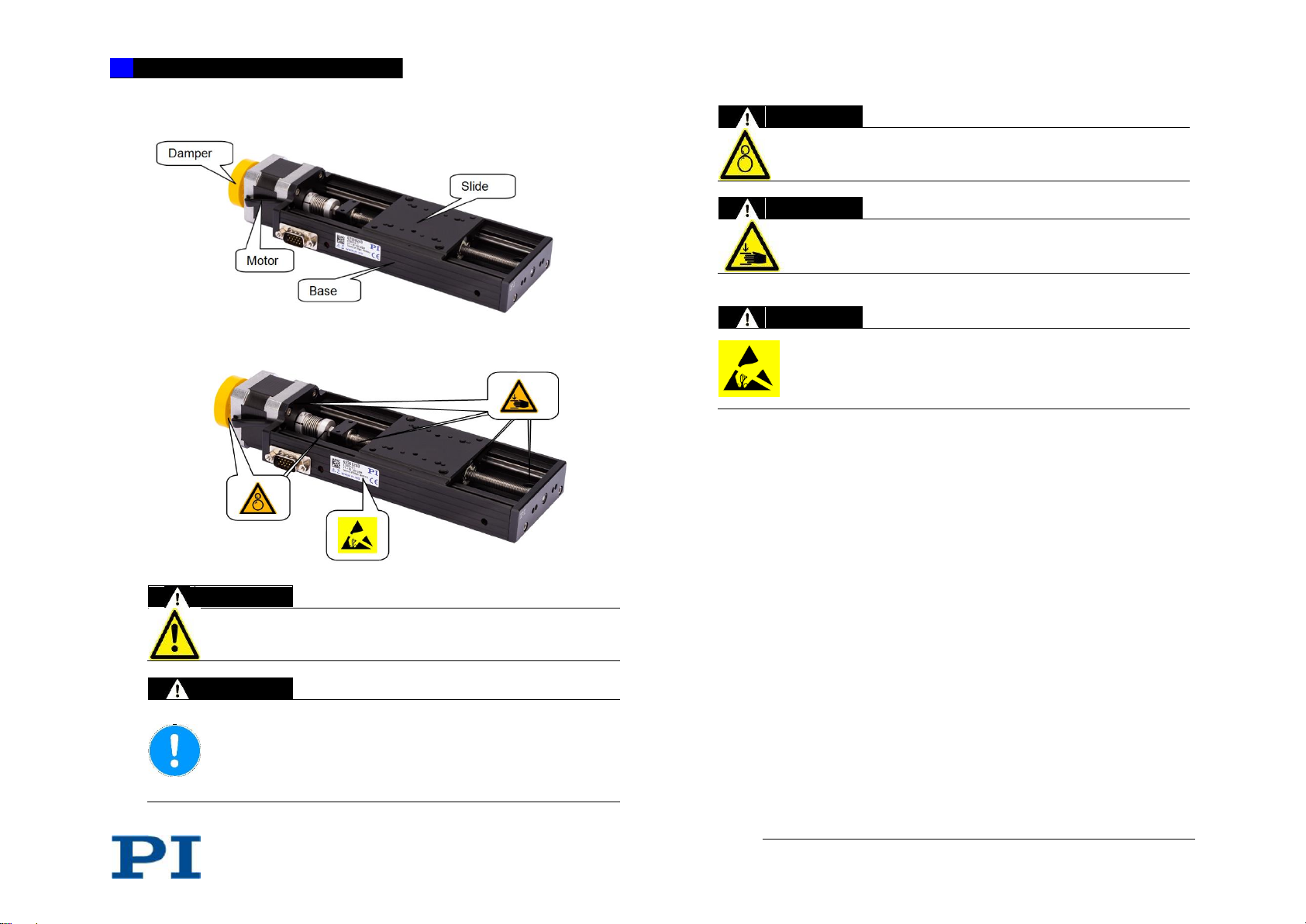
WARNING
After removing the transport lock (if present), watch out
for moving parts.
NOTICE
Protect the product against mechanical damage
(knocking, shock, ...).
Never start up an axis if you suspect it to be damaged
or broken.
Do not disconnect or connect connectors when voltage
is present.
WARNING
Risk of catching by rotating parts such as couplers and
ball screws
WARNING
Risk of squeezing or crushing by moving sliders at the
places illustrated.
WARNING
It is recommended that all persons entrusted with working
with this product and who therefore come into contact with
areas marked by the ESD warning symbol, are given
training and a comprehensive explanation of the ESD
warning symbol with respect to the ESD precautions.
4.3 Product View
4.4 Safety Instructions
4.5 Scope of Delivery
1. Stage according to order.
• Mounting accessories (screws & pins) in fast-sealing bag.
4.6 Optional Accessories
For optional accessories, please ask our customer service department
(chapter 9) for information on possible use of adapter plates or additional Zbrackets.
Page 9
VT-80 Translation Stage 9
www.pimicos.com // [email protected] // phone:+49(0)7634-50 57 0 // fax:+49(0)7634-50 57 393
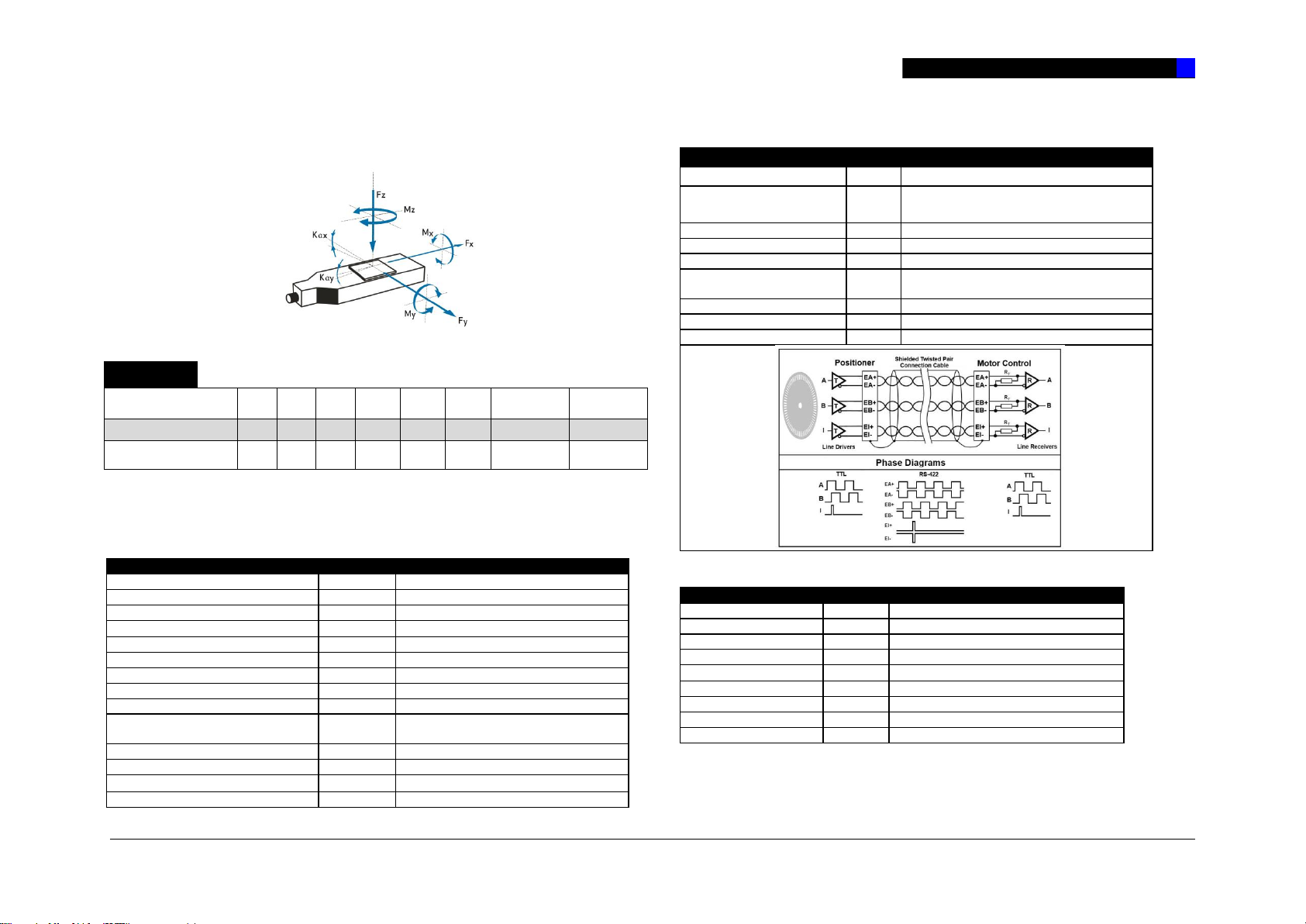
F A C T S
Load characteristics
Fx(N)
Fy(N)
Fz(N)
Mx(Nm)
My(Nm)
Mz(Nm)
kax(µrad/Nm)
kay(µrad/Nm)
DC
30
40
50 5 2.5
2.5
150
220
SM
30
40
50 5 2.5
2.5
150
220
Motor type
DC brush 2642-024 CR
Nominal voltage
V
24
Max. continuous current
A
1.1
Electrical resistance
5.78
Electrical inductance
mH
0.55
Torque constant
mNm/A
34.6
Velocity constant
rpm/V
276
n/M slope curve
rpm/mNm
46
No load velocity
rpm
6400
Max.continuous velocity at nominal
torque
rpm
4370
Inertia
kgm2
1.7E-6
Continuous torque
mNm
32
Rotary encoder
RE-010 RS422 2-channel + index
Encoder increments (quad counts)
n
2000
Encoder type
HEDL rotary optical encoder
Quadrature counts
per revolution
n
2000
Signal output
RS-422
Channels
2 + index
Supply voltage
VDC
4.5..5.5
Current consumption,
typical (Vcc = 5 V DC)
mA
57
Frequency range
KHz
100
Inertia of code disc
kgm2
0.5E-7
Operating temperature
°C
-40..100
Motor type
2 phase bipolar SH4118M1804
Phase current
A
1.8
Step angle
°
1.8 °
Steps
n
200
Coil resistance
1.1
Coil inductance
mH
1.85
Holding torque
mNm
280
Inertia
kgm2
5.7 E-6
Weight
kg
0.24
4.7 Technical Features
4.7.1 Technical Features
4.7.2 Motors
DC
RE-010 RS422
Rotary optical encoder RS-422 quadrature
SM
Page 10
10 VT-80 Translation Stage
Max. voltage (resistive load)
V
30
Max. current (resistive load)
A
1
Contact type
Normal closed
Operations
>5x10⁴
Operating temperature
°C
-40 to +85
HD15m
Function
1 EA+
Encoder channel A+
2
EB+
Encoder channel B+
3
EI+
Encoder channel I+
4
EGND
Supply encoder GND
5
nc 6
EA-
Encoder channel A-
7
EB-
Encoder channel B-
8
EI-
Encoder channel I-
9
E5V
Encoder supply voltage
10
nc 11
M+
DC brush motor +
12
M-
DC brush motor -
13
LE2
Limit forward
14
LE1
Limit reverse
15
LCOM
Limit common
HD15m
Function
1 MA+
Motor phase A+
2
MA-
Motor phase A-
3
nc 4
nc 5
MB+
Motor phase B+
6
MB-
Motor phase B-
7
nc 8
nc 9
nc 10
nc 11
nc 12
nc 13
LE2
Limit forward
14
LE1
Limit reverse
15
LCOM
Limit common
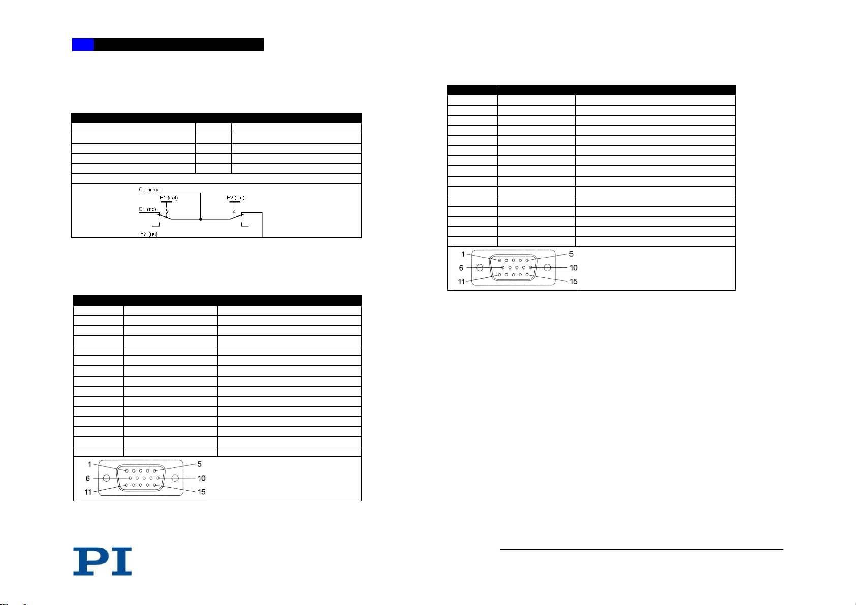
4.7.3 Limit Switch
Mechanical limit switches
4.7.4 Connector
DC motor, HD15 motor pin assignment with mechanical switches
2SM motor, HD15 motor pin assignment with mechanical sensors
Page 11
VT-80 Translation Stage 11
www.pimicos.com // [email protected] // phone:+49(0)7634-50 57 0 // fax:+49(0)7634-50 57 393
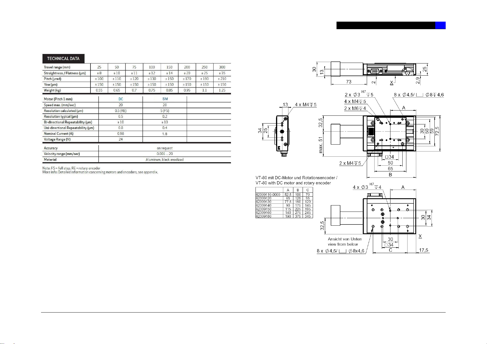
4.7.5 Technical Data
DC-Variants
Page 12
12 VT-80 Translation Stage
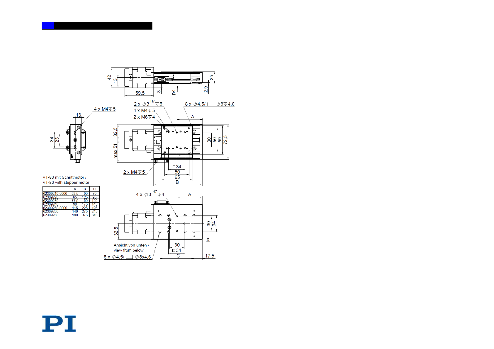
SM-Variants
4.8 Ambient Conditions
For indoor use only.
• The VT-80 was calibrated at an ambient temperature of 20 °C (+/- 3 °C).
• The permissible operating temperature is between + 5 °C and + 40 °C.
• The permissible relative humidity is between 20% and 80%.
• Always keep the VT-80 free of dirt, dust and corrosive gases.
Page 13
VT-80 Translation Stage 13
www.pimicos.com // [email protected] // phone:+49(0)7634-50 57 0 // fax:+49(0)7634-50 57 393
5. INSTALLATION
5.1 General Notes on Installation
Prerequisite
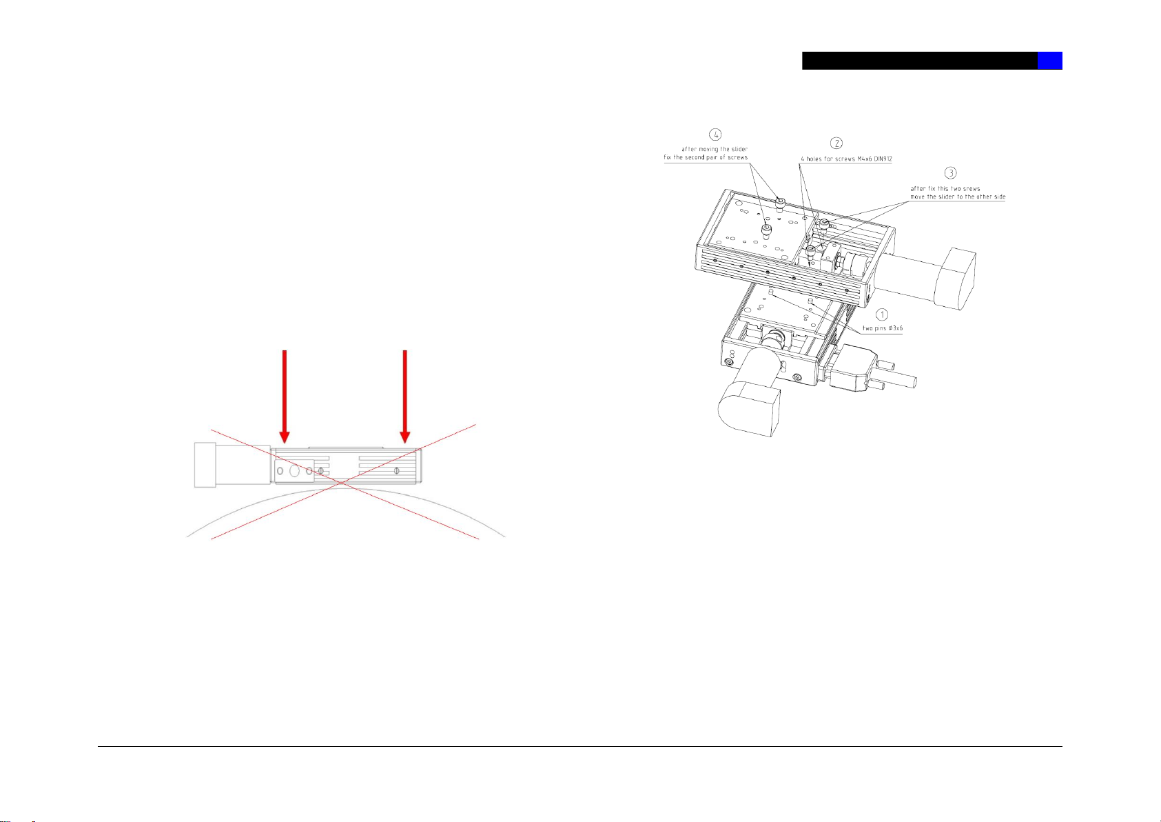
The axis must be screwed onto a surface with an evenness better than 5
µm.
It is necessary to make sure that no dust, dirt or other foreign bodies are
between the surface and the axis, otherwise the properties of the axis can
be impaired by mechanical tension.
To guarantee the prescribed specifications (see Internet www.pimicos.com),
the evenness of the mounting surface must be better than 5 µm. (Reference
surface of PI measuring granite is 3 µm).
5.2 Mounting the Stage
Prerequisite
You have read and understood the general notes on installation (see
chapter 5.1).
Mounting material
Screws, pins and auxiliary material or tools supplied (see chapter 4.5
"Scope of Delivery").
• DIN 912 screws and DIN 6325 dowel pins, m6 tolerance field
Tightening torques of the mounting screws to be used should not have
values higher than the following:
• M3 DIN 912 1.5 Nm
• M4 DIN 912 2.0 Nm
• M5 DIN 912 2.5 Nm
• M6 DIN 912 3.0 Nm
Page 14
14 VT-80 Translation Stage
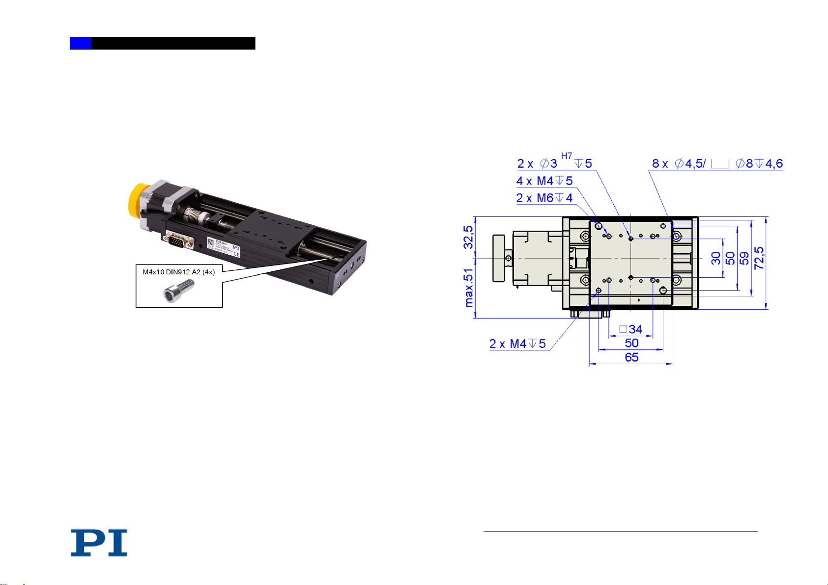
Mounting the VT-80
1. Displace the moving platform of the VT-80 to the center position by hand
until all of the countersunk holes in the base body required for mounting
accessible (see following illustration).
2. Mount the stage with the screws supplied.
3. Make sure that the screw heads do not protrude from the countersunk
holes.
5.3 Affixing the Load
Prerequisite
You have read and understood the general notes on installation
(see chapter 5.1).
Mounting material
• DIN 912 screws and DIN 6325 dowel pins, m6 tolerance field
Tightening torques of the mounting screws to be used should not have
values higher than the following:
• M3 DIN 912 1.5 Nm
• M4 DIN 912 2.0 Nm
• M5 DIN 912 2.5 Nm
• M6 DIN 912 3.0 Nm
Mounting the Additional Part
• Select the mounting position so that the existing fixing holes in the slider
of the VT-80 can be used for the additional part to be affixed.
• Mount the additional part with the corresponding screws.
Page 15
VT-80 Translation Stage 15
www.pimicos.com // [email protected] // phone:+49(0)7634-50 57 0 // fax:+49(0)7634-50 57 393
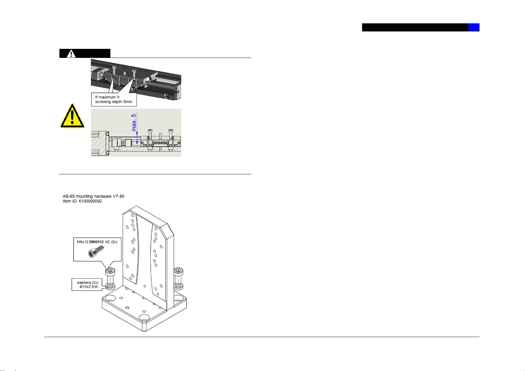
WARNING
Use M6 or M4 screws
with the corresponding
hole pattern to mount a
component onto the
slider of the VT-80. The
maximum depth for
screwing into the slider
plate is 5 mm.
Otherwise, the stage
could be damaged and
this will void the warranty.
.
Mounting the AB-65 Z Bracket
Please mount the AB-65 bracket only with the corresponding mounting
hardware. The screw lengths and the corresponding washers are matched
to the depth of the thread hole.
6. START-UP
6.1 General Notes on Start-Up
This stage must be started up with a suitable cable and the associated
controllers.
Page 16

16 VT-80 Translation Stage
7. MAINTENANCE
Depending on the operating conditions and the period of use of the VT-80,
the following maintenance measures are required:
Maintenance run
The maintenance run is performed to redistribute the existing lubricant on
the guidings of the stage.
• To evenly distribute the existing lubricant on the stage guidings, perform
a maintenance run across the entire travel range after 500 hours of
operation, or after 1 year at the latest.
• If you operate the translation stage continuously over a small travel
range (less than 20 percent of the entire travel range), perform a
maintenance run every 5000 motion cycles across the entire travel
range.
Lubrication
Under laboratory conditions, the guidings of the stage need to be lubricated
in exceptional cases only. For continuous industrial use, the lubrication
intervals must be defined individually.
• Do not lubricate the guidings of the VT-80 without consulting our
customer service department (see chapter 9).
• To lubricate the guidings, follow the instructions specified in the
maintenance manual, which you can obtain from our customer service
department.
8. TROUBLESHOOTING
If the problem that occurred with your system is not listed in the table above
or cannot be solved as described, contact our customer service department
(see chapter 9).
9. CUSTOMER SERVICE
For inquiries and orders, contact your PI miCos sales engineer or send us
and email ([email protected]).
If you have questions concerning your system, have the following
information ready:
Product codes and serial numbers of all products in the system
Current firmware version of the controller (if present)
Software version of the driver or the user software (if present)
User operating system (if present)
Page 17

VT-80 Translation Stage 17
www.pimicos.com // [email protected] // phone:+49(0)7634-50 57 0 // fax:+49(0)7634-50 57 393
10. OLD EQUIPMENT DISPOSAL
In accordance with EU directive 2002/96/EC (WEEE), as of 13 August 2005,
electrical and electronic equipment may not be disposed of in the member
states of the EU via the municipal residual waste.
Dispose of your old equipment according to international, national, and local
rules and regulations.
In order to fulfil the responsibility as the product manufacturer, PI GmbH
undertakes environmentally correct disposal of all old PI equipment made
available on the market after 13 August 2005 without charge.
Any old PI equipment can be sent free of charge to the following address:
PI GmbH
Freiburger Strasse 30
79427 Eschbach, Germany
http://www.pi.de
11. EU DECLARATION OF CONFORMITY
An EC Declaration of Conformity has been issued for the VT-80 in accordance with
the following European directives:
2014/30/EU, EMC Directive
2011/65/EU, RoHS Directive
The applied standards certifying the conformity are listed below.
EMV: EN 61326-1:2013
Safety: EN 61010-1:2010
DIN EN ISO 12100:2010
RoHS: EN 50581:2012
 Loading...