

Page 1
Physik Instrumente (PI) GmbH & Co. KG, Auf der Roemerstrasse 1, 76228 Karlsruhe, Germany
Phone +49 721 4846-0, Fax +49 721 4846-1019, Email [email protected], www.pi.ws
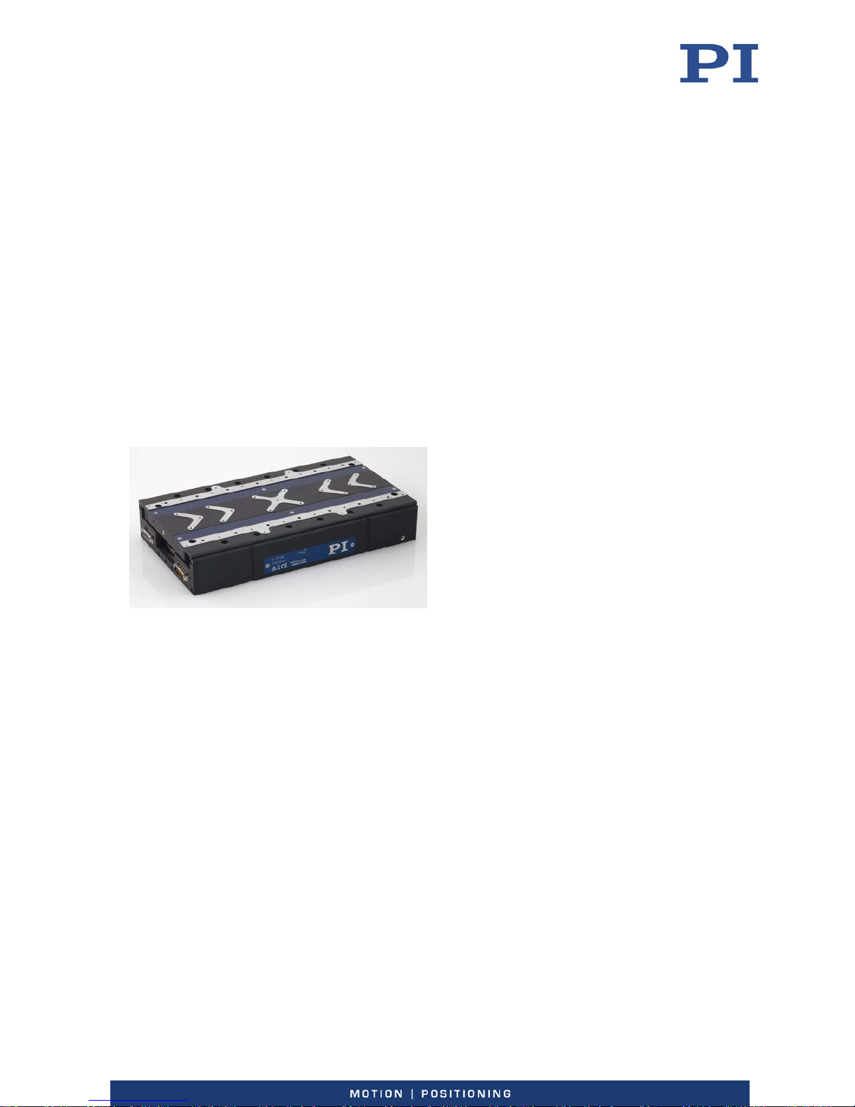
MP160E
V
-551 Linear Stage
User Manual
Version: 1.1.1
Date: 05.04.2019
This document describes the following products:
V-551.2D
PIMag® precision linear stage, 160 mm width,
60 mm travel range, 150
N load capacity, PIOne
linear encoder with sin/cos signal transmission,
2 µm sensor signal period, ironless 3-phase
linear motor
V-551.4D
PIMag® precision linear stage, 160 mm width,
130 mm travel range, 150 N load capacity,
PIOne linear encoder with sin/cos signal
transmission, 2 µm sensor signal period,
ironless 3-phase linear motor
V-551.7D
PIMag® precision linear stage, 160 mm width,
230 mm travel range, 150 N load capacity,
PIOne linear encoder with sin/cos signal
transmission, 2 µm sensor signal period,
ironless 3-phase linear motor
Page 2

The following company names and brands are registered trademarks of Physik Instrumente (PI) GmbH & Co.
KG:
PI®, NanoCube®, PICMA®, PILine®, NEXLINE®, PiezoWalk®, NEXACT®, Picoactuator®, PInano®, PIMag®,
Q-Motion®
Notes on brand names and third-party trademarks:
BiSS is a registered trademark of iC-Haus GmbH.
The patents held by PI are found in our patent list: http://www.physikinstrumente.com/en/about-pi/patents
© 2019 Physik Instrumente (PI) GmbH & Co. KG, Karlsruhe, Germany. The text, photographs, and drawings in
this manual are protected by copyright. With regard thereto, Physik Instrumente (PI) GmbH & Co. KG retains
all the rights. The use of any text, images and drawings is permitted only in part and only when indicating the
source.
Original instructions
First printing: 05.04.2019
Document number: MP160E, KSch, Version 1.1.1
Subject to change. This manual is superseded by any new release. The latest respective release is available for
download (p. 2) on our website.
Page 3

1 About this Document 1
1.1 Objective and Target Audience of this User Manual.................................................. 1
1.2 Symbols and Typographic Conventions...................................................................... 1
1.3 Figures ........................................................................................................................ 2
1.4 Other Applicable Documents ..................................................................................... 2
1.5 Downloading Manuals ................................................................................................ 2
2 Safety 5
2.1 Intended Use .............................................................................................................. 5
2.2 General Safety Instructions ........................................................................................ 5
2.3 Organizational Measures ............................................................................................ 6
3 Product Description 7
3.1 Model Overview ......................................................................................................... 7
3.2 Product View .............................................................................................................. 8
3.3 Product Labeling ......................................................................................................... 9
3.4 Scope of Delivery ........................................................................................................ 9
3.5 Accessories ............................................................................................................... 10
3.6 Suitable Controllers .................................................................................................. 10
3.7 Technical Features .................................................................................................... 10
3.7.1 Linear Encoder ............................................................................................. 10
3.7.2 Reference Point Switch ................................................................................ 10
3.7.3 Limit Switches .............................................................................................. 11
3.7.4 PIMag® Magnetic Direct Drive ..................................................................... 11
4 Unpacking 13
5 Installation 15
5.1 General Notes on Installation ................................................................................... 15
5.2 Connecting the V-551 to the Protective Earth Conductor ....................................... 16
5.3 Mounting the V-551 onto a Surface ......................................................................... 17
5.4 Setting Up a Multi-Axis System ................................................................................ 21
5.4.1 General Notes on Setting Up a Multi-Axis System ...................................... 21
5.4.2 Setting up the XY System without an Adapter ............................................ 22
5.4.3 Setting up the XY System with an Adapter .................................................. 24
5.5 Option: Modifying the Travel Range ........................................................................ 27
5.6 Fixing the Load to the V-551 .................................................................................... 31
5.7 Connecting the Motor Cable and Sensor Cable to the V-551 .................................. 33
Contents
Page 4

6 Startup and Operation 35
6.1 General Notes on Startup and Operation ................................................................ 35
6.2 Starting Up the V-551 with the C-891 Controller ..................................................... 38
7 Maintenance 41
7.1 General Notes on Maintenance ............................................................................... 41
7.2 Preparing the V-551 for Transport ........................................................................... 41
7.3 Cleaning the V-551 ................................................................................................... 41
8 Troubleshooting 43
9 Customer Service 45
10 Technical Data 47
10.1 Specifications ............................................................................................................ 47
10.1.1 Data Table .................................................................................................... 47
10.1.2 Maximum Ratings ........................................................................................ 49
10.1.3 Ambient Conditions and Classifications ...................................................... 49
10.1.4 Reference Point Switch Specifications ........................................................ 49
10.1.5 Limit Switch Specifications .......................................................................... 49
10.2 Dimensions ............................................................................................................... 50
10.2.1 V-551.2D ...................................................................................................... 50
10.2.2 V-551.4D ...................................................................................................... 54
10.2.3 V-551.7D ...................................................................................................... 58
10.2.4 V-551.AP1 Adapter ...................................................................................... 61
10.3 Pin Assignment ......................................................................................................... 62
10.3.1 Sensor .......................................................................................................... 62
10.3.2 Motor ........................................................................................................... 63
11 Old Equipment Disposal 65
12 EU Declaration of Conformity 67
Page 5
1 About this Document
V-551 Linear Stage MP160E Version: 1.1.1 1
In this Chapter
Objective and Target Audience of this User Manual ..................................................................... 1
Symbols and Typographic Conventions ......................................................................................... 1
Figures ............................................................................................................................................ 2
Other Applicable Documents ......................................................................................................... 2
Downloading Manuals ................................................................................................................... 2
1.1 Objective and Target Audience of this User Manual
This manual contains information on the intended use of the V-551.
It assumes that the reader has a fundamental understanding of basic servo systems as well as
motion control concepts and applicable safety procedures.
The latest versions of the user manuals are available for download (p. 2) on our website.
1.2 Symbols and Typographic Conventions
The following symbols and typographic conventions are used in this user manual:
CAUTION
Dangerous situation
Failure to comply could lead to minor injury.
Precautionary measures for avoiding.
NOTICE
Dangerous situation
Failure to comply could cause damage to equipment.
Precautionary measures for avoiding.
INFORMATION
Information for easier handling, tricks, tips, etc.
1
About this Document
Page 6
1 About this Document
2 Version: 1.1.1 MP160E V-551 Linear Stage
Symbol/Label Meaning
1.
2.
Action consisting of several steps whose sequential order must
be observed
Action consisting of one or several steps whose sequential order
is irrelevant
List item
p. 5 Cross-reference to page 5
RS-232 Labeling of an operating element on the product (example:
socket of the RS-232 interface)
Warning sign on the product which refers to detailed information
in this manual.
1.3 Figures
For better understandability, the colors, proportions, and degree of detail in illustrations can
deviate from the actual circumstances. Photographic illustrations may also differ and must not
be seen as guaranteed properties.
1.4 Other Applicable Documents
The devices and software tools from PI mentioned in this documentation are described in their
own manuals.
Product Document
C-891 PIMag® Motor Controller MS251E User Manual
PIMikroMove
SM148E Software Manual
1.5 Downloading Manuals
INFORMATION
If a manual is missing or problems occur with downloading:
Contact our customer service department (p. 45).
INFORMATION
For products that are supplied with software (CD in the scope of delivery), access to the
manuals is protected by a password. Protected content is only displayed on the website after
entering the access data.
You need the product CD to get the access data.
Page 7

1 About this Document
V-551 Linear Stage MP160E Version: 1.1.1 3
For products with CD: Get access data
1. Insert the product CD into the PC drive.
2. Switch to the Manuals directory on the CD.
3. In the Manuals directory, open the Release News (file including releasenews in the file
name).
4. Get the access data for downloading protected content in the "User login for software
download" section of the Release News. Possible methods for getting the access data:
− Link to a page for registering and requesting the access data
− User name and password is specified
5. If the access data needs to be requested via a registration page:
a) Follow the link in the Release News.
b) Enter the required information in the browser window.
c) Click Show login data in the browser window.
d) Note the user name and password shown in the browser window.
Downloading manuals
If you have requested access data for protected contents via a registration page (see above):
Click the links in the browser window to change to the content for your product and log
in using the access data that you received.
General procedure:
1. Open the website www.pi.ws.
2. If access to the manuals is protected by a password:
a) Click Login.
b) Log in with the user name and password.
3. Click Search.
4. Enter the product number up to the period (e.g., P-882) or the product family (e.g.,
PICMA® Bender) into the search field.
5. Click Start search or press the Enter key.
6. Open the corresponding product detail page in the list of search results:
a) If necessary: Scroll down the list.
b) If necessary: Click Load more results at the bottom of the list.
c) Click the corresponding product in the list.
7. Click the Downloads tab.
The manuals are shown under Documentation.
8. Click the desired manual and save it to the hard disk of your PC or to a data storage
medium.
Page 8

Page 9

2 Safety
V-551 Linear Stage MP160E Version: 1.1.1 5
In this Chapter
Intended Use .................................................................................................................................. 5
General Safety Instructions............................................................................................................ 5
Organizational Measures ............................................................................................................... 6
2.1 Intended Use
The V-551 is a laboratory device as defined by DIN EN 61010-1. It is intended for indoor use and
use in an environment that is free of dirt, oil, and lubricants.
The V-551 has a PIMag® magnetic direct drive and an incremental-measuring position sensor. In
accordance with its design, the V-551 is intended for positioning, adjusting and shifting loads in
one axis at various velocities.
The V-551 is intended for operation with a horizontally aligned motion axis. With a vertically
aligned motion axis, the V-551 may only be operated with suitable gravity compensation (not in
the scope of delivery).
The V-551 is not intended for applications in areas in which a failure would present severe risks
to human beings or the environment.
The intended use of the V-551 is only possible when completely installed and in conjunction
with a suitable controller (p. 10). The controller is not included in the scope of delivery of the
V-551.
2.2 General Safety Instructions
The V-551 is built according to state-of-the-art technology and recognized safety standards.
Improper use can result in personal injury and/or damage to the V-551.
Use the V-551 for its intended purpose only, and only when it is in perfect technical
condition.
Read the user manual.
Eliminate any faults and malfunctions likely to affect safety immediately.
The operator is responsible for the correct installation and operation of the V-551.
2
Safety
Page 10

2 Safety
6 Version: 1.1.1 MP160E V-551 Linear Stage
2.3 Organizational Measures
User manual
Always keep this user manual available with the V-551.
The latest versions of the user manuals are available for download (p. 2) on our
website.
Add all information from the manufacturer to the user manual, for example
supplements or technical notes.
If you give the V-551 to other users, also include this user manual as well as other
relevant information provided by the manufacturer.
Use the device only if the user manual is complete. Missing information due to an
incomplete user manual can result in minor injury and damage to equipment.
Install and operate the V-551 only after you have read and understood this user
manual.
Personnel qualification
The V-551 may only be installed, started, operated, maintained, and cleaned by authorized and
appropriately qualified personnel.
Page 11
3 Product Description
V-551 Linear Stage MP160E Version: 1.1.1 7
In this Chapter
Model Overview ............................................................................................................................. 7
Product View .................................................................................................................................. 8
Product Labeling ............................................................................................................................ 9
Scope of Delivery ........................................................................................................................... 9
Accessories ................................................................................................................................... 10
Suitable Controllers ..................................................................................................................... 10
Technical Features ....................................................................................................................... 10
3.1 Model Overview
Three standard versions of the V-551 are available. They differ with regard to the travel range
and therefore the dimensions.
Model Travel range Dimension
V-551.2D 60 mm 220 mm × 160 mm × 50.5 mm
V-551.4D
130 mm
290 mm × 160 mm × 50.5 mm
V-551.7D 230 mm 450 mm × 160 mm × 50.5 mm
For further technical data, see the specifications (p. 47).
3
Product Description
Page 12
3 Product Description
8 Version: 1.1.1 MP160E V-551 Linear Stage
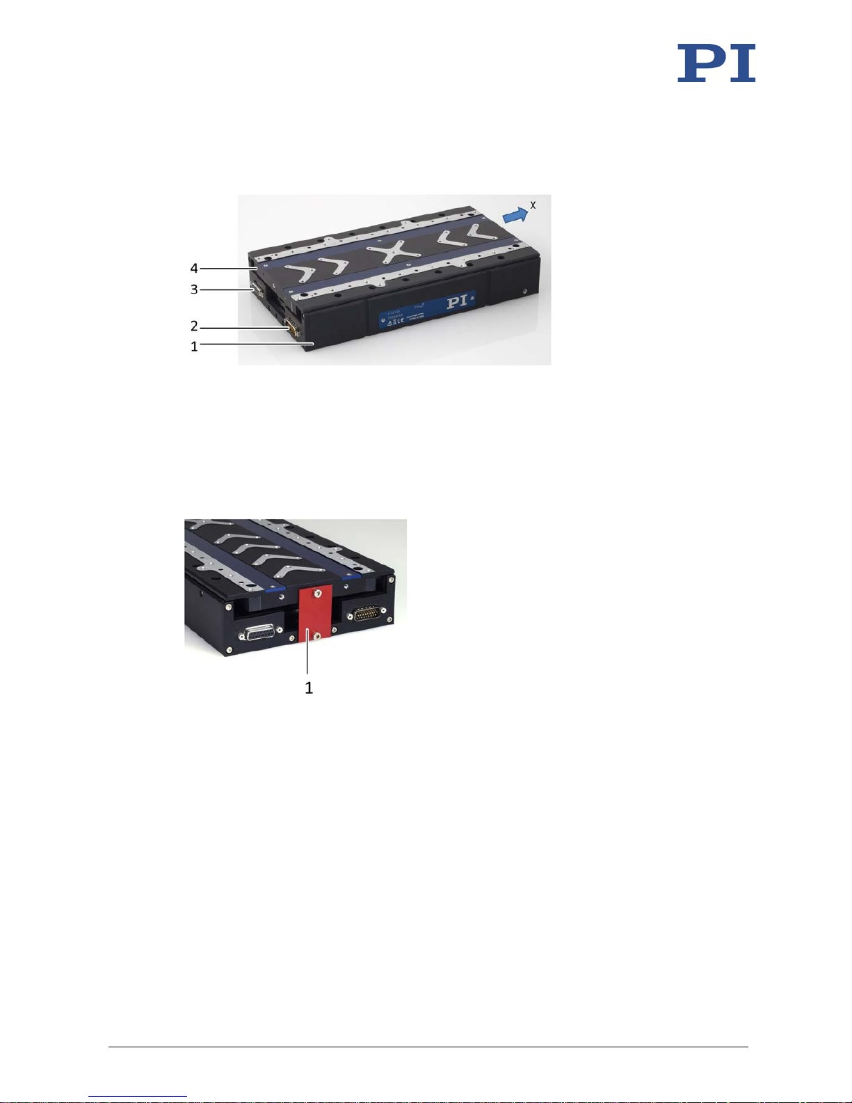
3.2 Product View
Figure 1: V-551.4D
1 Base body
2 Connection for motor cable (panel plug, HD Sub-D 26)
3 Connection for sensor cable (socket, Sub-D 15)
4 Motion platform
x Positive direction of motion
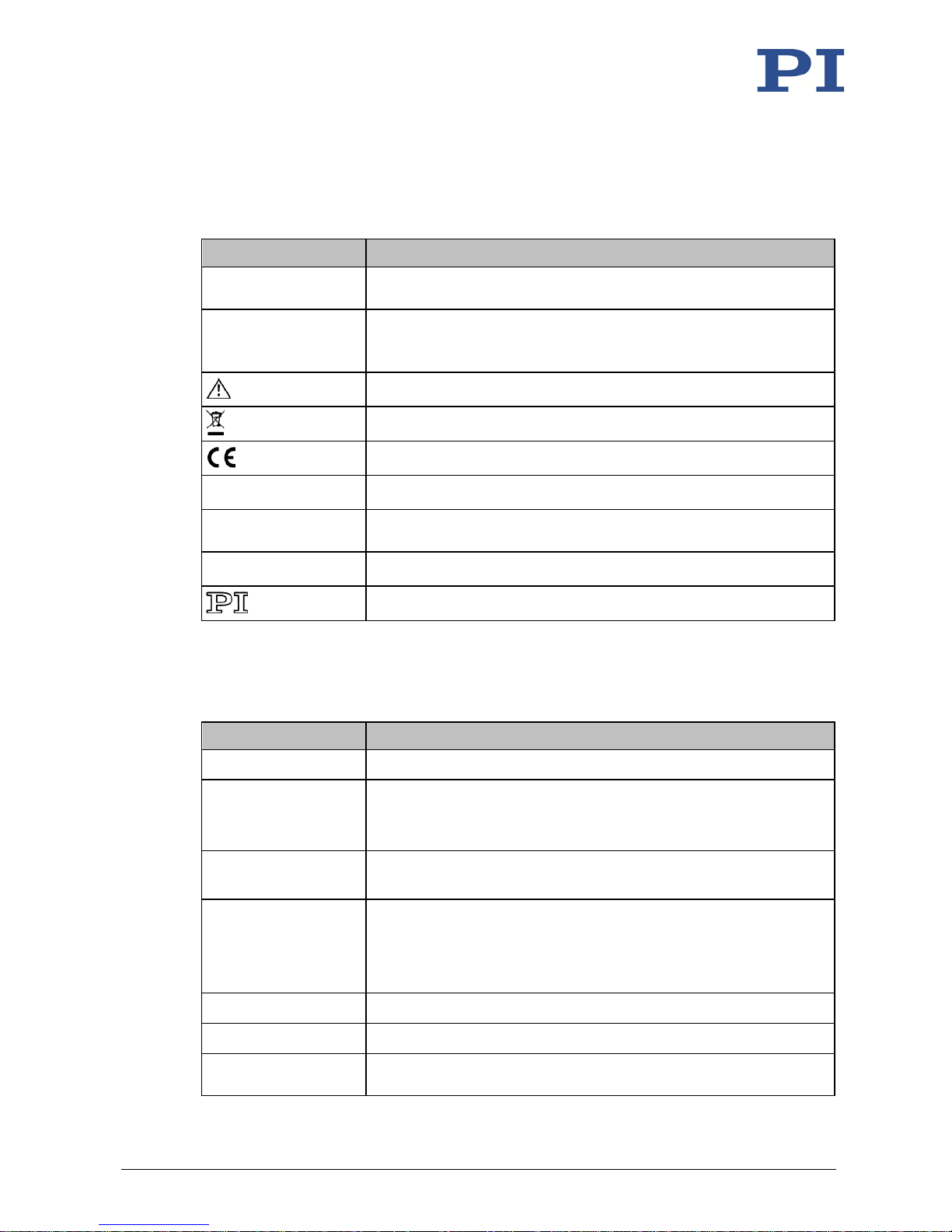
Figure 2: V-551 with transport safeguard, identical for all models
1 Transport safeguard (plate with 2 M4x12 screws)
Page 13
3 Product Description
V-551 Linear Stage MP160E Version: 1.1.1 9
3.3 Product Labeling
There is a type plate on the base body of the V-551 that contains the following information:
Labeling Description
V-551.4D
Product name (example), the characters following the period refer to
the model
115003601
Serial number (example), individual for each V-551
Meaning of each position (from the left): 1 = internal information,
2 and 3 = year of manufacture, 4 to 9 = consecutive number
Warning sign "Pay attention to the manual!"
Old equipment disposal (p. 65)
CE conformity mark
PIMag® Brand name of the drive
Country of origin:
Germany
Country of origin
WWW.PI.WS Manufacturer's address (website)
Manufacturer's logo
3.4 Scope of Delivery
Item number Component
V-551 Linear stage according to the order (p. 7)
-
Transport safeguard, consisting of:
1 plate, 30 mm × 45 mm, red anodized
2 socket head screws, A2 M4x12 ISO 4762
1890
Screw set for mounting the V-551, consisting of:
4 socket head screws, A2 M6x30 ISO 4762
000036450
M4 screw set for protective earth, consisting of:
1 flat-head screw with cross recess, M4x8, ISO 7045
2 safety washers
2 flat washers
K020B0089 Motor cable, HD Sub-D 26 (m/f), 3 m
K030B0936 Sensor cable, Sub-D 15 (m/f), 3 m
MP163EK
Short instructions for V-408, V-508, V-52x, and V-551 PIMag® stages in
printed form
Page 14
3 Product Description
10 Version: 1.1.1 MP160E V-551 Linear Stage
3.5 Accessories
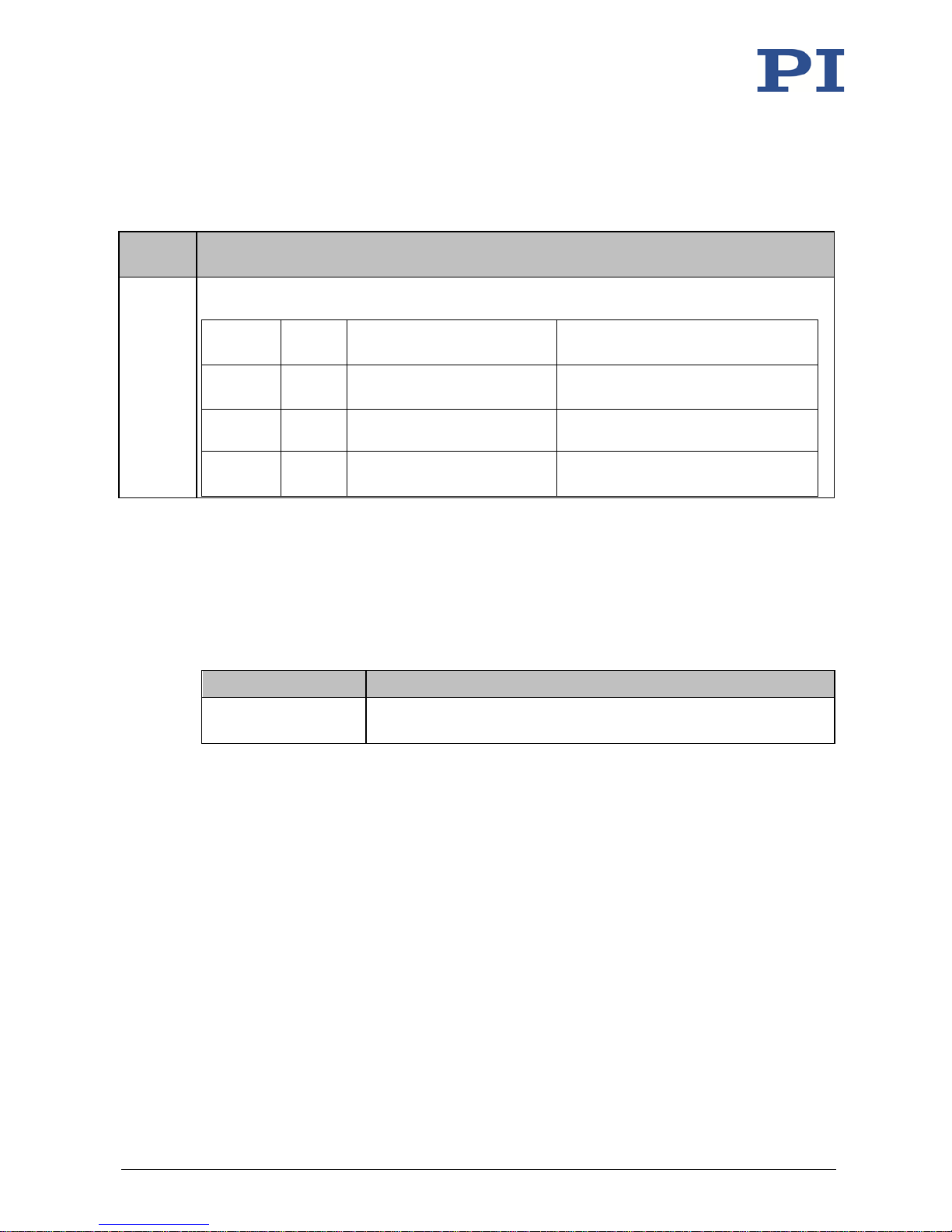
Order
number
Description
V-551.AP1
Adapter for setting up an XY system when the upper stage is a V-551.7D. Material: Aluminum
alloy, anodized, mass: 580 g; including the following socket head screws:
Item
number
Quantity
Description Comment
#1295 4 pcs. M4x10, DIN EN ISO 4762, A2 Mounting the V-551.AP1 onto the
X axis
#1890 4 pcs. M6x30, DIN EN ISO 4762, A2 Mounting the V-551.7D onto the
V-551.AP1
#1421
4 pcs.
M6x10, DIN EN ISO 4762, A2
Mounting the V-551.7D onto the
V-551.AP1
To order, contact our customer service department (p. 45).
3.6 Suitable Controllers
The V-551 must be connected to a suitable controller. The following controller from PI is
suitable for operating the V-551:
Controller Description
C-891.130300 PIMag® motion controller for magnetic direct drives, 1 axis, 24/48 V,
5 A, USB and RS-232 interface
PC software is included in the scope of delivery of the controllers from PI. The operation of the
controllers is described in the corresponding user manuals.
3.7 Technical Features
3.7.1 Linear Encoder
The V-551 is equipped with an optical linear encoder. For the resolution, refer to the table in
the "Specifications" section (p. 47).
Optical linear encoders measure the actual position directly (direct metrology). Therefore,
errors occurring in the drivetrain such as nonlinearity, backlash or elastic deformation, cannot
influence the measurement of the position.
3.7.2 Reference Point Switch
The V-551 has an optical reference point switch (see "Reference Switch Specifications" (p. 49)).
See the controller user manual and/or associated software manuals for the commands that
make use of the reference point signal.
Page 15

3 Product Description
V-551 Linear Stage MP160E Version: 1.1.1 11
3.7.3 Limit Switches
The V-551 is equipped with noncontact, Hall-effect limit switches.
Each limit switch sends an overrun signal on a dedicated line to the controller. The controller
then stops the motion. If the controller does not stop the motion in time, the stage runs into
the hard stop.
See "Limit Switch Specifications" (p. 49) for more information.
3.7.4 PIMag® Magnetic Direct Drive
The V-551 is equipped with a PIMag® ironless magnetic direct drive for high velocity and
acceleration. The drive allows a high position resolution with long travel ranges due to its sinecommutated drive.
Magnetic direct drives have advantages when compared to classical spindle-based solutions,
especially with respect to wear and dynamics. Because they use as few mechanical components
as possible, there is less friction and backlash and therefore more precision and a longer
lifetime.
Page 16

Page 17
4 Unpacking
V-551 Linear Stage MP160E Version: 1.1.1 13
NOTICE
Mechanical overload from incorrect handling!
An impermissible mechanical load on the V-551 due to transportation without a transport
safeguard can damage the motion platform of the V-551 as well as cause loss of accuracy.
Only ship the V-551 in the original packaging and with the transport safeguard installed.
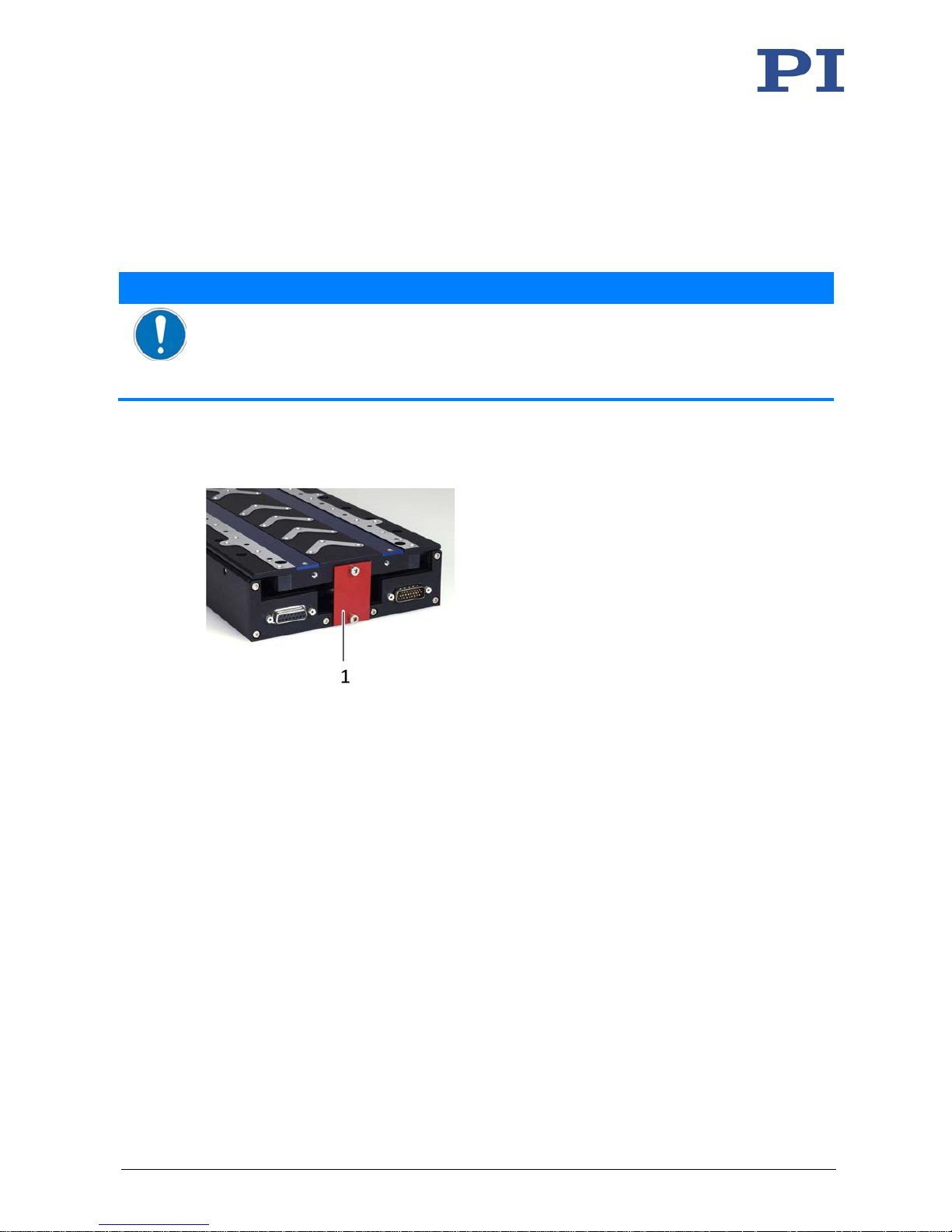
The V-551 is delivered with a transport safeguard installed.
Figure 3: V-551 with transport safeguard, identical for all models
1 Transport safeguard (plate with 2 M4x12 screws)
Tools and accessories
Hex key AF 3
Unpacking the V-551
1. Unpack the V-551 with care.
2. Compare the contents with the items listed in the contract and the packing list. If parts
are incorrectly supplied or missing, contact PI immediately.
3. Inspect the contents for signs of damage. If you notice signs of damage, contact PI
immediately.
4. Remove the transport safeguard:
a) Loosen and remove both M4 screws.
b) Remove the plate.
5. Keep all packaging materials and the transport safeguard in case the product needs to
be transported later.
4
Unpacking
Page 18

Page 19
5 Installation
V-551 Linear Stage MP160E Version: 1.1.1 15
In this Chapter
General Notes on Installation ...................................................................................................... 15
Connecting the V-551 to the Protective Earth Conductor ........................................................... 16
Mounting the V-551 onto a Surface ............................................................................................ 17
Setting Up a Multi-Axis System .................................................................................................... 21
Option: Modifying the Travel Range ............................................................................................ 27
Fixing the Load to the V-551 ........................................................................................................ 31
Connecting the Motor Cable and Sensor Cable to the V-551 ...................................................... 33
5.1 General Notes on Installation
NOTICE
Attraction of magnetizable objects!
The magnets on the bottom side of the motion platform of the V-551 can attract magnetizable
objects such as loose screws. Objects attracted can damage the V-551.
Make sure that there are no movable, magnetizable objects within a radius of at least
10 cm around the motion range of the platform of the V-551.
NOTICE
Damage to magnetically sensitive objects!
The magnets on the bottom side of the motion platform of the V-551 can damage magnetically
sensitive objects such as magnetic data carriers and electronic devices.
Make sure that there are no magnetically sensitive objects within a radius of at least 10 cm
around the motion range of the platform of the V-551.
NOTICE
Heating up of the V-551 during operation!
The heat produced during operation of the V-551 can affect your application.
Install the V-551 so that the application is not affected by the dissipated heat.
Ensure sufficient ventilation at the place of installation.
Make sure that the complete bottom side of the V-551 is in contact with the surface on
which the V-551 is mounted.
5
Installation
Page 20
5 Installation
16 Version: 1.1.1 MP160E V-551 Linear Stage
NOTICE
Lubricants, dirt, condensation!
Dirt, oil, lubricants and condensation will render the motor/drive inoperable.
Keep the V-551 free from lubricants.
Keep the V-551 free from dirt and condensation.
INFORMATION
The V-551 is intended for operation with a horizontally aligned motion axis. With a vertically
aligned motion axis, the V-551 may only be operated with suitable gravity compensation (not
in the scope of delivery).
Contact our customer service department (p. 45) for details on gravity compensation.
INFORMATION
For the positive direction of motion of the motion platform, see "Product View" (p. 8).
5.2 Connecting the V-551 to the Protective Earth Conductor
INFORMATION
Pay attention to the applicable standards for connecting the protective earth conductor.
The V-551 has an M4 threaded hole for attaching the protective earth conductor. This hole is
marked with the symbol for the protective earth conductor
(see "Dimensions" (p. 50)).
Requirements
You have read and understood the general notes on installation (p. 15).
The stage is not connected to the controller.
Tools and accessories
Suitable protective earth conductor: Cross-sectional area of the cable ≥ 0.75 mm
2
Supplied M4 protective earth screw set (p. 9) for connecting the protective earth
conductor
Suitable screwdriver
Page 21
5 Installation
V-551 Linear Stage MP160E Version: 1.1.1 17
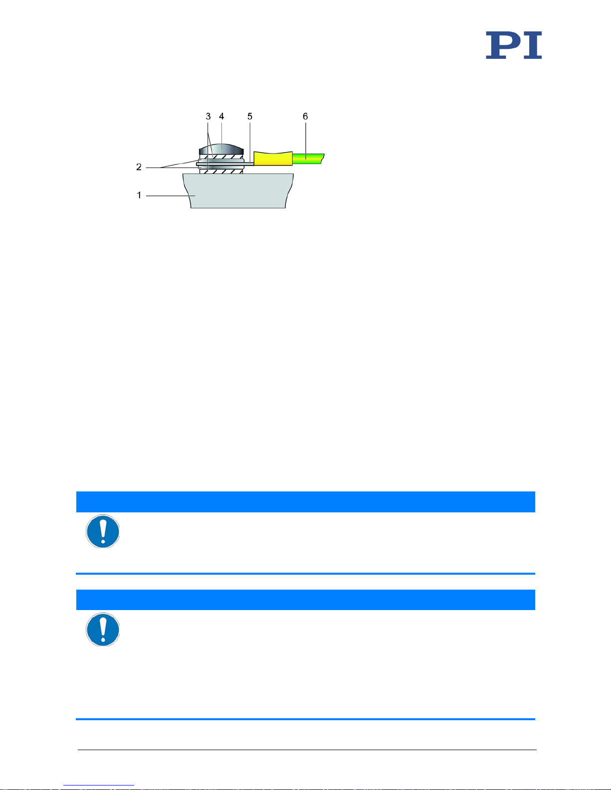
Figure 4: Connecting the protective earth conductor (profile view)
1 Base body of the V-551
2 Flat washer
3 Safety washer
4 Screw
5 Cable lug
6 Protective earth conductor
Connecting the V-551 to the protective earth conductor
1. If necessary, attach a suitable cable lug to the protective earth conductor.
2. Use the M4 screw (together with the washers and self-locking washers) to affix the
cable lug of the protective earth conductor to the protective earth connection of the
V-551 as shown in the profile view.
3. Tighten the M4 screw with a torque of 1.2 Nm to 1.5 Nm.
4. Make sure that the contact resistance at all connection points relevant for connecting
the protective earth conductor is <0.1 Ω at 25 A.
5.3 Mounting the V-551 onto a Surface
NOTICE
Protruding screw heads!
Protruding screw heads can damage the V-551.
Ensure that the screw heads do not protrude from countersunk holes so that they do not
interfere with the motion.
NOTICE
Warping of the V-551 when mounted on uneven surfaces!
Mounting the V-551 onto an uneven surface can warp the V-551. Warping reduces the
accuracy.
Mount the V-551 onto an even surface. The recommended evenness of the surface is
≤20 µm.
For applications with large temperature changes:
Only mount the V-551 onto surfaces that have the same or similar thermal expansion
properties as the V-551 (e.g., surfaces made of aluminum).
Page 22
5 Installation
18 Version: 1.1.1 MP160E V-551 Linear Stage
INFORMATION
The mounting holes that are needed for mounting from above are only accessible when the
motion platform is displaced to the end of the factory-set travel range. If you want to modify
the travel range of the V-551 by displacing the hard stops (p. 27):
Mount the V-551 on the surface before modifying the travel range.
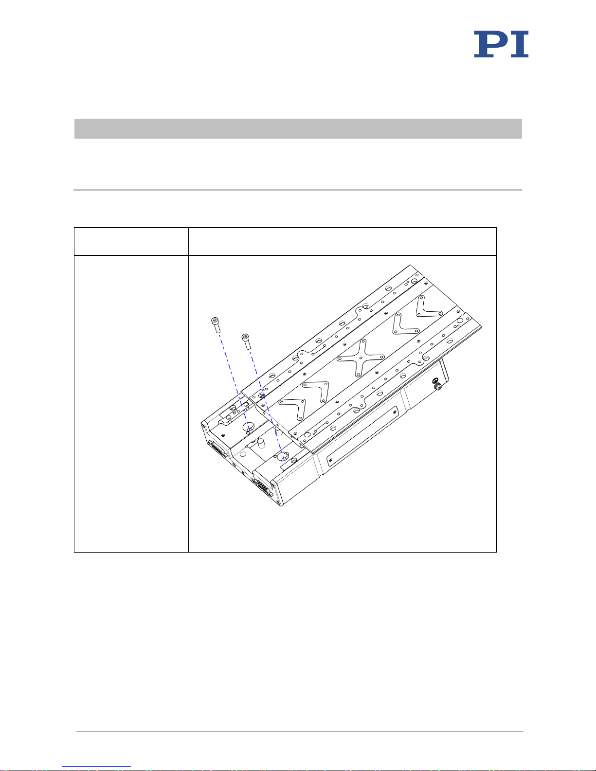
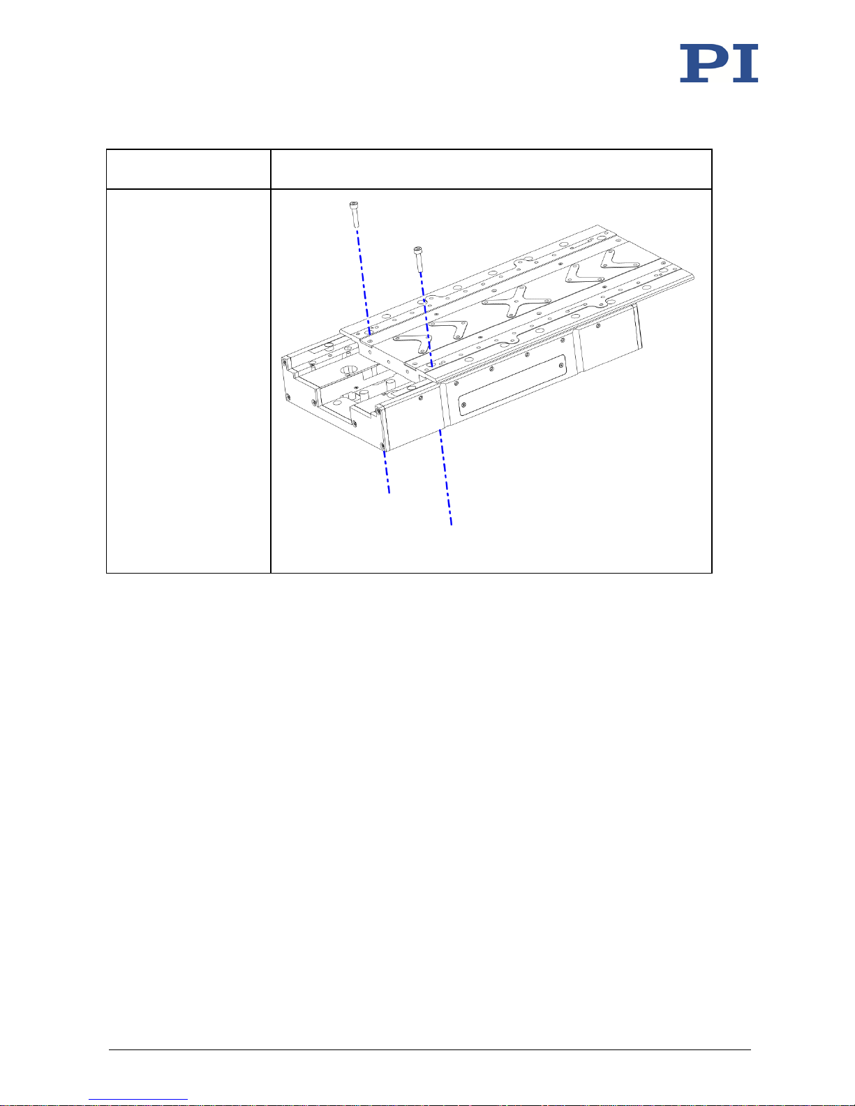
The mounting holes of the V-551 are intended for the following mounting options:
Mounting option Mounting holes, details see "Dimensions" (p. 50)
Mounting from above
using four M6x30 screws
The motion platform must
be pushed to the end of
the travel range each time
to make the mounting
holes accessible.
Figure 5: Mounting of the V-551 from above with four M6x30 screws, two of
four screws shown here
Page 23
5 Installation
V-551 Linear Stage MP160E Version: 1.1.1 19
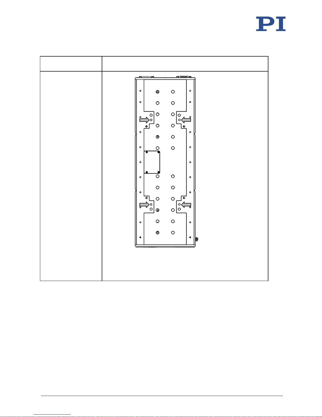
Mounting option Mounting holes, details see "Dimensions" (p. 50)
Mounting from above
using four M4x30 screws
The motion platform must
be pushed to the end of
the travel range each time
to make the mounting
holes accessible.
This mounting option is
used for example, when
setting up an XY system
consisting of two
V-551.2D or V-551.4D
stages (p. 22).
Figure 6: Mounting the V-551 from above using four M4x30 screws
Page 24
5 Installation
20 Version: 1.1.1 MP160E V-551 Linear Stage
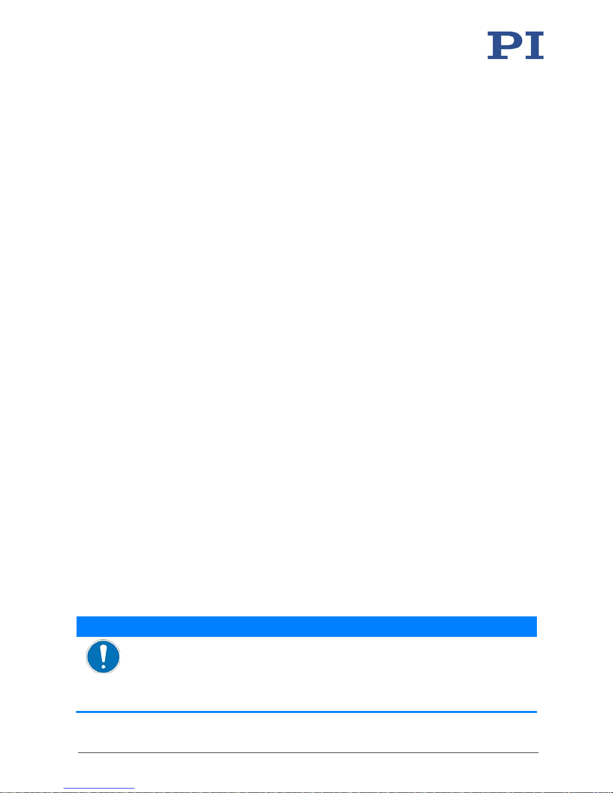
Mounting option Mounting holes, details see "Dimensions" (p. 50)
Mounting from below
using four M6 screws
This mounting option is
used for example, when
setting up an XY system
and the upper stage is a
V-551.7D (p. 24).
Figure 7: Mounting the V-551 from below with four M6 screws; here:
V-551.7D. The position of the M6 holes with a depth of 8 mm is
different for the V-551 models
Requirements
You have read and understood the general notes on installation (p. 15).
The V-551 is not connected to the controller.
You have provided a suitable surface (for the required position and depth of the holes
for accommodating the screws, see "Dimensions" (p. 50)):
− For mounting from above: Four M6 or M4 threaded holes are provided.
− For mounting from below: Four Ø 6.4 mm through holes are provided.
− For applications with large temperature changes: The surface should have the same
thermal expansion properties as the V-551 (e.g., surface made of aluminum).
− The flatness of the surface is ≤20 µm.
Page 25
5 Installation
V-551 Linear Stage MP160E Version: 1.1.1 21
You have accounted for the space required to route cables without bending and
according to regulations.
Tools and accessories
Mounting accessories:
− For mounting from above: 4 M6x30 screws (in the scope of delivery (p. 9)) or
4 M4 screws of suitable length
− For mounting from below: 4 M6 screws of suitable length
Suitable tools for tightening the screws
Mounting the V-551 on a surface
1. Align the stage on the surface so that the corresponding mounting holes in the stage
and the surface overlap.
2. Completely screw in the screws into all mounting holes.
For mounting from above:
− Move the motion platform to the factory-set end of the travel range each time to
make the mounting holes accessible.
Maximum permissible torque:
− M6: 8.8 Nm
− M4: 2.6 Nm
3. Check that the stage is affixed firmly to the surface.
5.4 Setting Up a Multi-Axis System
The V-551 can be used in XY systems.
Designations in these instructions:
Lower stage: Forms the basis of the multi-axis system (X axis); is mounted on a surface
Upper stage: Forms the Y axis of the multi-axis system; is mounted on the lower stage
rotated by 90°
5.4.1 General Notes on Setting Up a Multi-Axis System
NOTICE
Impermissibly high load on the stages!
In an XY system, the stage for the Y-axis must be moved as well. Impermissibly high loads
interfere with the motion and can damage the stages.
Include the mass of the moved stage in the calculation of the load to be moved.
For all stages in a multi-axis system: Do not exceed the maximum permissible load.
Page 26
5 Installation
22 Version: 1.1.1 MP160E V-551 Linear Stage
NOTICE
Protruding screw heads!
Protruding screw heads can damage the V-551.
Ensure that the screw heads do not protrude from countersunk holes so that they do not
interfere with the motion.
NOTICE
Screws that are too long!
Screws that are inserted too deeply can damage the lower stage.
Observe the depth of the mounting holes in the motion platform (p. 50) of the lower stage.
Only use screws of the correct length for the respective mounting holes.
INFORMATION
Any model of the V-551 can be used as lower or upper stage.
If a V-551.7D is to be used as the upper stage, an adapter is required, see "Accessories" (p. 10).
INFORMATION
The mounting holes that are needed for mounting the upper stage are only accessible when
the motion platform is moved to the factory-set end of the travel range (exception: Mounting
a V-551.7D from below). If you want to change the travel range of the upper stage by
displacing the hard stops (p. 27):
Mount the upper stage on the lower stage before modifying the travel range.
5.4.2 Setting up the XY System without an Adapter
The XY system is set up without an adapter when a V-551.2D or a V-551.4D is used as upper
stage.
Requirements
You have read and understood the general notes on installation (p. 15).
You have read and understood the general notes on setting up a multi-axis system
(p. 21).
The used stages are disconnected from the controller.
You have properly mounted the lower stage onto a surface (p. 17).
You have accounted for the space required to route cables without bending and
according to regulations.
Tools and accessories
4 M4x30 screws
Suitable screwdriver
Page 27
5 Installation
V-551 Linear Stage MP160E Version: 1.1.1 23
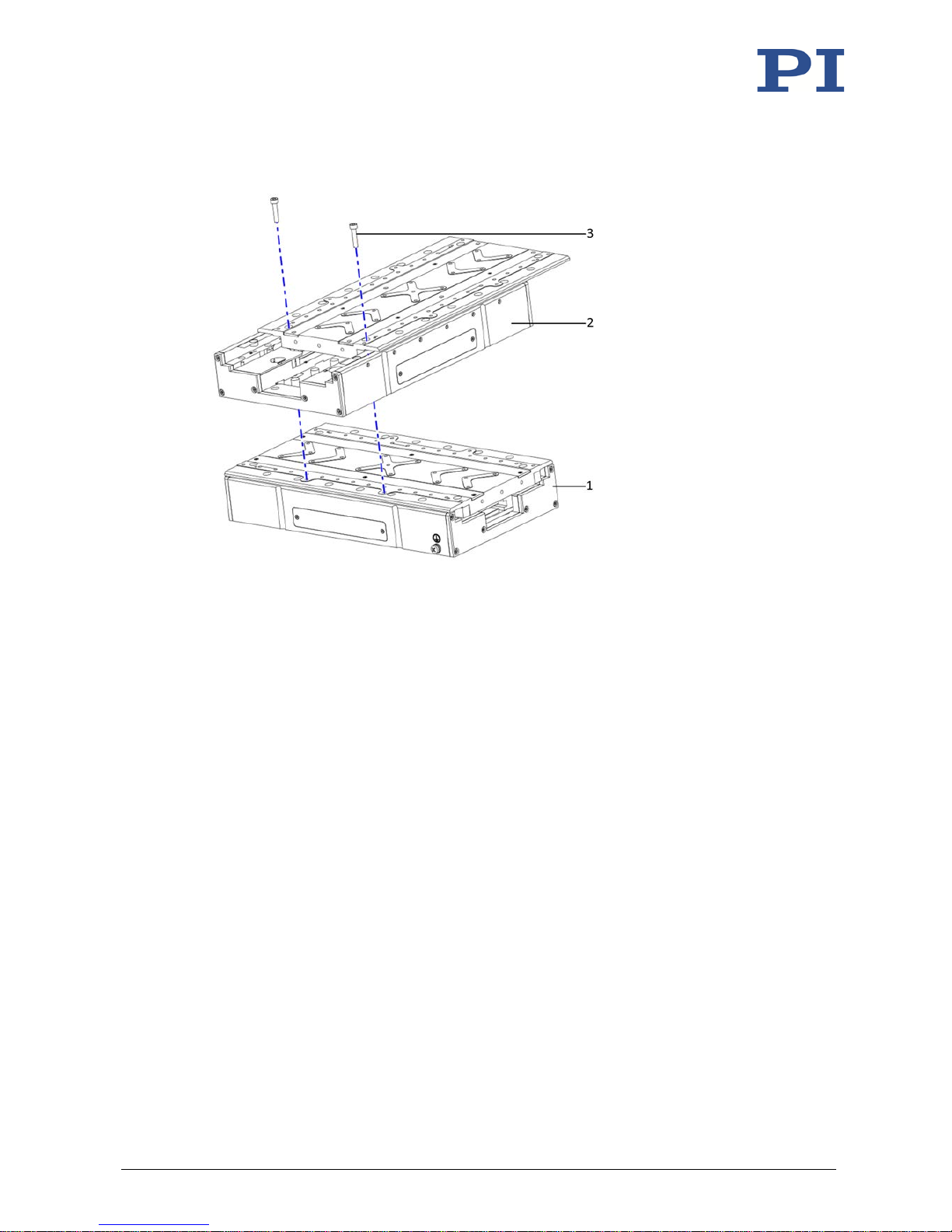
Setting up the XY system without an adapter
Figure 8: Example V-551.4D on V-551.4D: Setting up an XY system without an adapter
1 Lower stage
2 Upper stage
3 2 of 4 M4x30 screws
1. Align the upper stage on the lower stage so that the corresponding mounting holes
overlap.
2. Tighten the screws in all mounting holes completely.
− Move the motion platform to the factory-set end of the travel range each time to
make the mounting holes accessible.
− Maximum permissible torque: 2.6 Nm
3. Check that the upper stage is affixed firmly.
Page 28
5 Installation
24 Version: 1.1.1 MP160E V-551 Linear Stage
5.4.3 Setting up the XY System with an Adapter
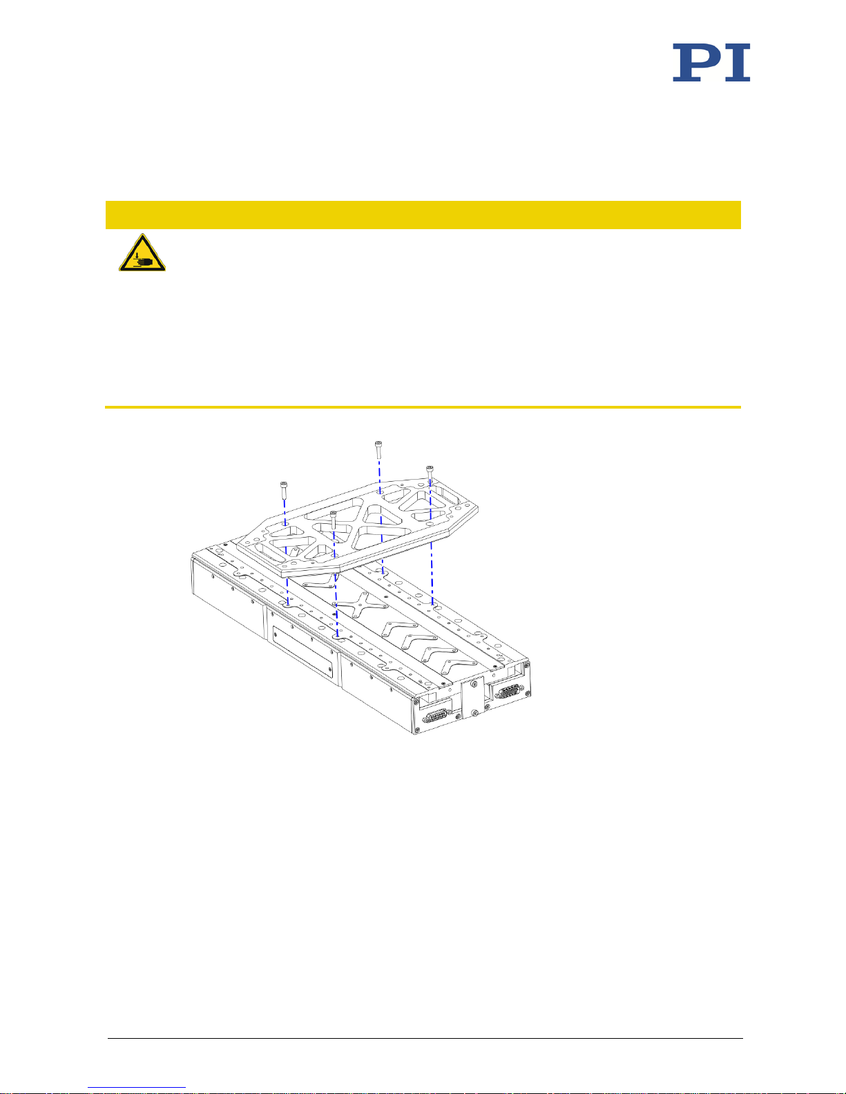
The XY system is set up with an adapter when a V-551.7D is used as upper stage.
CAUTION
Risk of crushing by falling parts!
During setup of an XY system, a risk of minor injury from crushing is possible when parts fall off
in the following situations:
− When mounting from below: When the XY system is tilted by 180°
− When mounting from above: When you move the platform of the upper stage (change
in center of gravity)
Observe the total weight of the XY system.
Wear safety shoes.
Prevent the upper stage from falling when its platform is moved.
Figure 9: Mounting the V-551.AP1 adapter to the lower stage (here V-551.7D) using four M4x10
screws
Page 29
5 Installation
V-551 Linear Stage MP160E Version: 1.1.1 25
The following options are provided for mounting the upper stage on the adapter:
Options for mounting on
adapter
Mounting holes, details see "Dimensions" (p. 50)
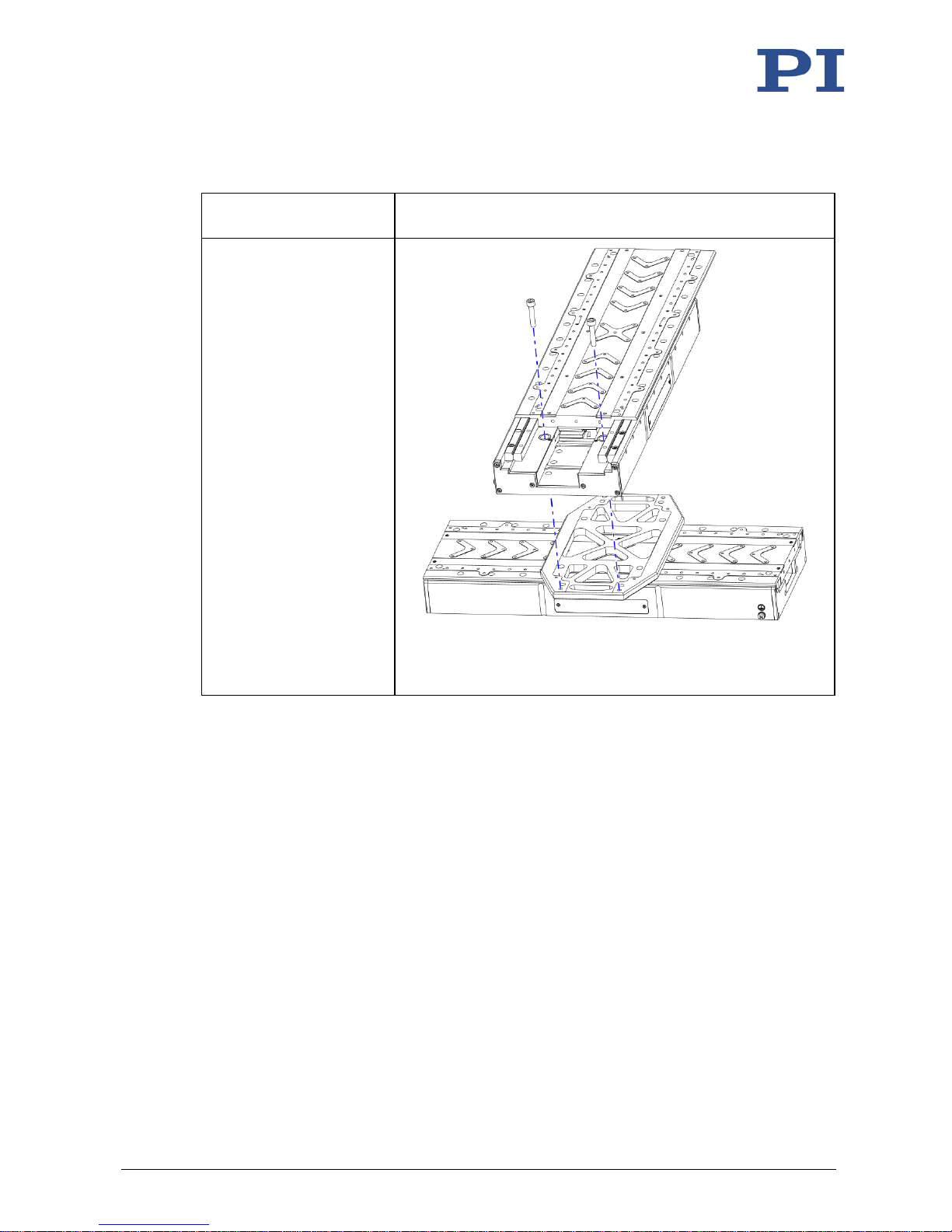
Mounting from above with
four M6x30 screws
The motion platform of the
upper stage must be
pushed to the end of the
travel range each time to
make the mounting holes
accessible.
Figure 10: Mounting the V-551.7D from above with four M6x30
screws, shown here with two of four screws
Page 30
5 Installation
26 Version: 1.1.1 MP160E V-551 Linear Stage
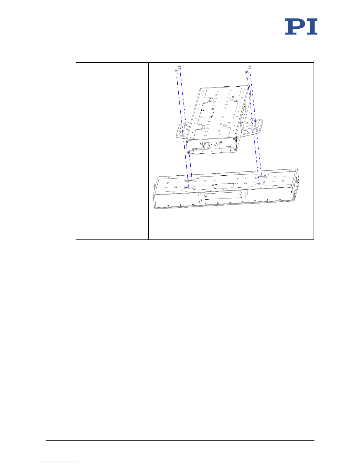
Mounting from below with
four M6x10 screws
If necessary for mounting
the upper stage, the XY
system can be tilted
temporarily by 180° so that
it is vertical. The upper
stage is then at the bottom,
and the bottom sides of the
stage and the adapter are
facing up.
Figure 11: Mounting the V-551.7D from below with four M6x10
screws; XY system tilted by 180° so that it is vertical
Requirements
You have read and understood the general notes on installation (p. 15).
You have read and understood the general notes on setting up a multi-axis system
(p. 21).
The used stages are disconnected from the controller.
You have accounted for the space required to route cables without bending and
according to regulations.
Tools and accessories
V-551.AP1 adapter, available as optional accessory (p. 10)
Screws in the scope of delivery of the adapter:
− 4 M4x10 screws
− Depending on the option selected for mounting the V-551.7D onto the adapter:
4 M6x30 or 4 M6x10 screws
When the lower stage has not been mounted onto a surface yet: 4 suitable screws; see
"Mounting the V-551 on a Surface" (p. 17)
When you tilt the XY system vertically by 180°: Safety shoes
Page 31
5 Installation
V-551 Linear Stage MP160E Version: 1.1.1 27
Setting up an XY system with an adapter
1. Mount the adapter on the lower stage:
a) Make sure that the counterbores on the four holes with Ø 4.5 mm in the adapter
are facing upwards.
b) Align the adapter on the lower stage as in the above figure.
c) Mount the adapter with four M4x10 screws, maximum permissible torque: 2.6 Nm.
d) Check that the adapter is affixed firmly.
2. Mount the upper stage on the adapter:
a) When mounting from below: If necessary, tilt the upper stage and the lower stage,
on which the adapter is mounted, vertically by 180°.
b) Align the upper stage and the adapter to each other so that the corresponding
mounting holes overlap.
c) Tighten in the four M6 screws; options see above. When mounting from above:
Move the motion platform to the factory-set end of the travel range each time to
make the mounting holes accessible. Maximum permissible torque: 8.8 Nm.
d) Check that the upper stage is affixed firmly.
3. When the stage has not been mounted onto a surface yet:
When you have tilted the XY system by 180° so that it is vertical:
a) Observe the total weight of the XY system and wear safety shoes.
b) Attach the transport safeguards to both stages (p. 41).
c) Tilt the XY system vertically by 180° again so that the motion platform of the upper
stage is facing upwards again.
d) Remove the transport safeguards from both stages (p. 13).
− Follow the instructions in "Mounting the V-551 on a Surface" (p. 17).
5.5 Option: Modifying the Travel Range
The travel range of the V-551 can be changed by displacing the integrated hard stops.
NOTICE
Improper displacement of the hard stops!
Improper displacement of the hard stops damages the V-551.
Do not let any screws or other foreign bodies fall inside the V-551.
After displacement of the hard stops, make sure that the two adjustable parts are present
and properly mounted.
Attach the cover again after displacing the hard stops.
Page 32
5 Installation
28 Version: 1.1.1 MP160E V-551 Linear Stage
INFORMATION
The hard stops are set for the travel range at the factory according to the specifications (p. 47).
Displacing the hard stops reduces the factory-set travel range.
The mounting holes for mounting the V-551 from above are only accessible with the default
setting for the travel range.
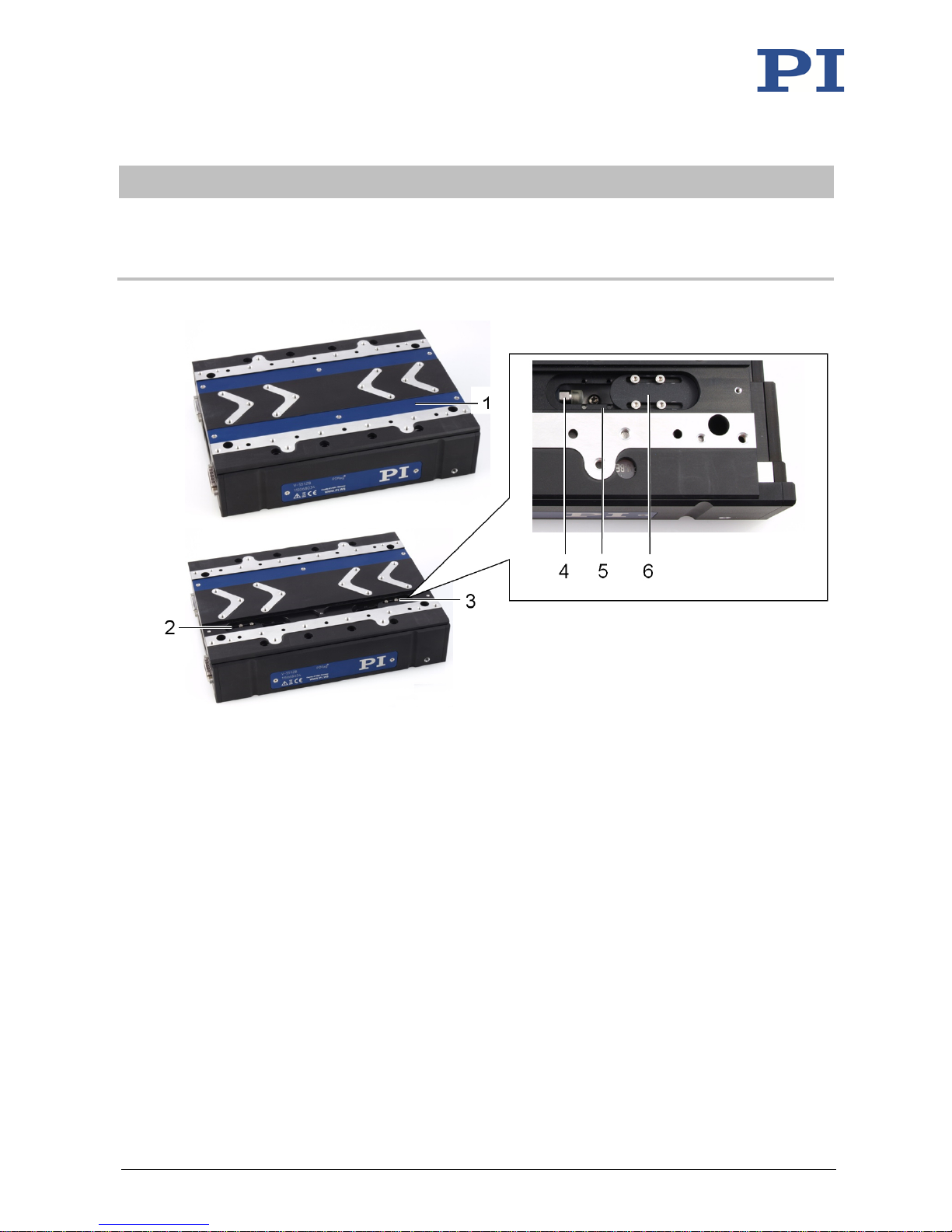
Figure 12: Hard stops of the V-551, overview and detailed view of a hard stop
1 Cover for the hard stops (on the side that faces the type plate)
Accessible after removal of the cover:
2 Hard stop for limiting the travel range in the positive direction of motion
3 Hard stop for limiting the travel range in the negative direction of motion
4 Detail: Fixed buffer of the hard stop
5 Detail: Recess with eight M2 holes
6 Detail: Adjustable part of the hard stop, with two longitudinal holes for fine alignment
Page 33
5 Installation
V-551 Linear Stage MP160E Version: 1.1.1 29
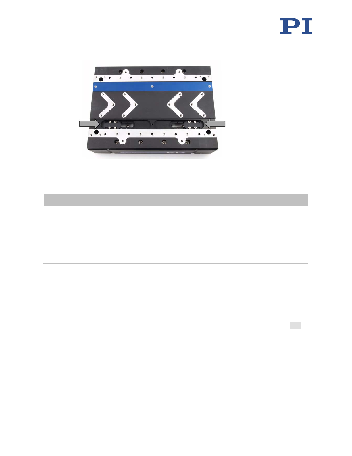
Figure 13: Factory setting of the hard stops of the V-551: The outer edge of each adjustable part
touches the edge of the recess in the motion platform; see arrows.
INFORMATION
If you want to check the setting of the hard stops while changing the travel range:
1. Connect the V-551 to the controller via the sensor cable (p. 33).
2. Start up the controller and establish communication between the controller and PC; see
documentation of the controller.
3. Read the current position of the axis of the V-551 in the used PC software; see the
documentation of the controller and/or the PC software.
Requirements
You have read and understood the general notes on installation (p. 15).
You have properly mounted the stage onto a surface or on a V-551 (p. 17).
The drive of the V-551 is deactivated. Options:
− The motor cable is not connected to the V-551.
− When operated with the C-891 controller: The drive is switched off with the EAX
command.
You know the travel range required for a collision-free application.
Tools and accessories
TX6 Torx screwdriver
Modifying the travel range
1. Remove the cover of the hard stops:
a) Loosen the three M2 screws.
Page 34
5 Installation
30 Version: 1.1.1 MP160E V-551 Linear Stage
b) Carefully remove the screws and place them sufficiently far away (minimum
distance to the bottom side of the motion platform: 10 cm).
c) Pull the cover up and away from the motion platform.
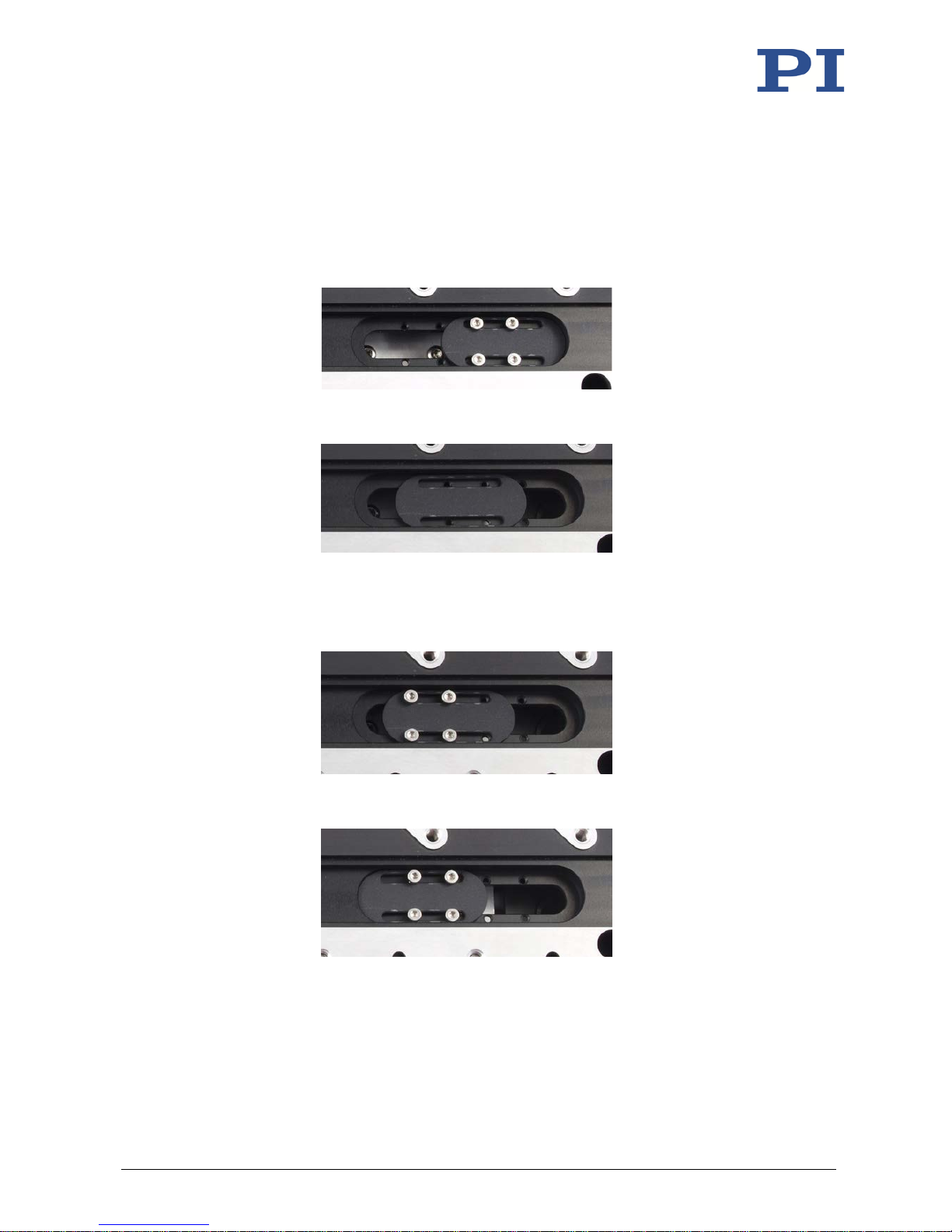
2. Displace one hard stop:
a) Loosen the four M2 screws on the adjustable part of the stop.
Example:
b) Carefully remove the screws and place them sufficiently far away (minimum
distance to the bottom side of the motion platform: 10 cm).
Example:
c) Coarse alignment: Move the adjustable part of the hard stop so that it can be
mounted with four of the eight M2 holes.
d) Insert the four M2 screws into the corresponding holes, but do not completely
tighten them yet.
Example:
e) Fine alignment: Move the adjustable part of the hard stop along the longitudinal
holes until the desired travel range is achieved.
Example:
f) Tighten the four screws with a maximum torque of 0.3 Nm each.
g) Check that the adjustable part is affixed firmly.
3. If necessary, move the second hard stop according to the instructions in step 2.
4. Adjust the parameters for the soft limits of the axis to the changed travel range on the
controller; see documentation of the controller.
Page 35
5 Installation
V-551 Linear Stage MP160E Version: 1.1.1 31
5.6 Fixing the Load to the V-551
NOTICE
Impermissibly high forces and torques!
Impermissibly high forces and torques that are applied to the motion platform can damage the
V-551.
For affixing type and mass of the load, pay attention to the maximum permissible forces
according to the specifications (p. 47).
Avoid tilting torques at the motion platform.
NOTICE
Screws that are too long!
Screws inserted too deeply damage the V-551.
Pay attention to the maximum screw-in depth for the mounting holes (p. 50).
Only use screws of the correct length for the respective mounting holes.
Page 36
5 Installation
32 Version: 1.1.1 MP160E V-551 Linear Stage
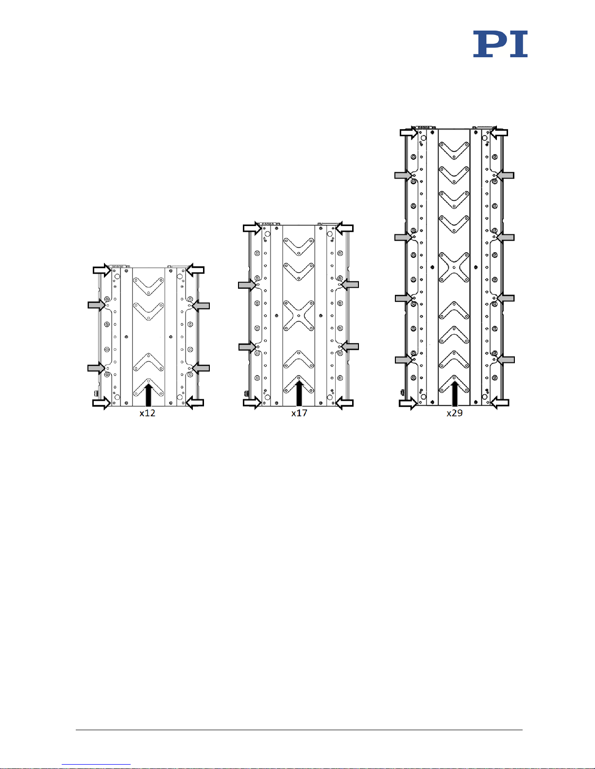
Figure 14: Mounting holes for affixing the load; from the left: V-551.2D, V-551.4D, V-551.7D
The arrows identify the following mounting holes in the motion platform of the V-551:
White arrows: M4 threaded holes, depth 5.5 mm
Gray arrows: M4 threaded holes, depth 4.5 mm
Black arrows: M4 threaded holes, depth 8 mm
Requirements
You have read and understood the general notes on installation (p. 15).
You have properly mounted the stage onto a surface (p. 16) or on a V-551 (p. 21).
The V-551 is not connected to the controller.
You have prepared the load so that it can be affixed to the motion platform (for the
required position and depth of the holes for accommodating the screws, see
"Dimensions" (p. 50)):
− The distance between the center of gravity of the load and the center of the motion
platform is as small as possible in all directions.
− At least three points are provided for affixing the load on the motion platform.
Page 37

5 Installation
V-551 Linear Stage MP160E Version: 1.1.1 33
Tools and accessories
Four M4 screws of suitable length (p. 50)
Suitable tool for tightening the screws
Affixing the load to the V-551
1. Align the load on the V-551 so that the mounting holes in the load and the holes in the
motion platform overlap.
2. Affix the load to the mounting holes with the screws:
− Maximum permissible torque for M4 screws: 2.6 Ncm
3. Check that load is affixed firmly.
5.7 Connecting the Motor Cable and Sensor Cable to the V-551
Requirements
You have read and understood the general notes on installation (p. 15).
Motor cable and sensor cable are not connected to the controller.
Tools and accessories
K020B0089 motor cable, HD Sub-D 26 (m/f), 3 m in the scope of delivery (p. 9)
K030B0936 sensor cable, Sub-D 15 (m/f), 3 m in the scope of delivery (p. 9)
Suitable controller
Connecting the motor cable and sensor cable to the V-551
1. Connect the cable:
− Connect the connector (f) of the motor cable to the 26-pin HD Sub-D panel plug (m)
of the V-551.
− Connect the connector (m) of the sensor cable to the 15-pin Sub-D socket (f) of the
V-551.
2. Use the integrated screws to secure the connector (f) and the connector (m) against
accidental disconnection from the V-551.
Page 38

Page 39
6 Startup and Operation
V-551 Linear Stage MP160E Version: 1.1.1 35
In this Chapter
General Notes on Startup and Operation .................................................................................... 35
Starting Up the V-551 with the C-891 Controller ........................................................................ 38
6.1 General Notes on Startup and Operation
The startup of the V-551 is done with the PIMag® C-891 motion controller from PI.
CAUTION
Risk of crushing by moving parts!
There is a risk of minor injuries from crushing between the moving parts of the stage or the
load and a fixed part or obstacle.
Use protective structures to keep limbs away from areas in which they could be caught by
moving parts.
Observe the safety distances in accordance with DIN EN ISO 13857 when installing
protective structures.
NOTICE
Damage due to collisions!
Collisions can damage the stage, the load to be moved, and the surroundings.
Make sure that no collisions are possible between the stage, the load to be moved, and the
surroundings in the motion range of the stage.
Do not place any objects in areas where they can be caught by moving parts.
Stop the motion immediately if a controller malfunction occurs.
If possible, adapt the travel range limits of your mechanical system in the software that
you use for commanding the motion.
NOTICE
Damage from transport safeguard that has not been removed!
Damage can occur to the stage if the transport safeguard (p. 13) of the stage has not been
removed and a motion is commanded.
Remove the transport safeguard before you start up the system consisting of the stage and
the controller.
6
Startup and Operation
Page 40
6 Startup and Operation
36 Version: 1.1.1 MP160E V-551 Linear Stage
NOTICE
Damage from improper or incomplete installation!
The V-551 can develop high forces and accelerations. If the V-551 has been improperly or
incompletely installed, the V-551, the load, and the surroundings can be damaged during
operation.
Only start up the system when the V-551 and the load have been correctly mounted; see
"Installation" (p. 15).
NOTICE
Attraction of magnetizable objects!
The magnets on the bottom side of the motion platform of the V-551 can attract magnetizable
objects such as loose screws. Objects attracted can damage the V-551.
Make sure that there are no movable, magnetizable objects within a radius of at least
10 cm around the motion range of the platform of the V-551.
NOTICE
Damage to magnetically sensitive objects!
The magnets on the bottom side of the motion platform of the V-551 can damage magnetically
sensitive objects such as magnetic data carriers and electronic devices.
Make sure that there are no magnetically sensitive objects within a radius of at least 10 cm
around the motion range of the platform of the V-551.
NOTICE
Heating up of the V-551 during operation!
The heat produced during operation of the V-551 can affect your application.
Ensure sufficient ventilation at the place of installation.
Ensure that the effective nominal current and the peak current do not exceed the
permissible values (p. 47).
Page 41
6 Startup and Operation
V-551 Linear Stage MP160E Version: 1.1.1 37
NOTICE
Undesired displacement due to lack of self-locking!
The drive of the V-551 does not have self-locking. The V-551 can therefore unintentionally
move in the following cases:
Switching off the controller
Rebooting the controller
Switching off the servo mode for the axis
Switching off the drive for the axis
Safety switch-off by the controller due to overtemperature or overcurrent
Unintentional displacement can damage the stage, the load to be moved, and the
surroundings.
Only operate the V-551 with a horizontally aligned motion axis.
If you want to operate the V-551 with a vertically aligned motion axis: Attach suitable
gravity compensation (not in the scope of delivery). Contact our customer service
department (p. 45) for details on gravity compensation.
Before switching off or rebooting the controller, take suitable measures to ensure that no
unintentional displacement of the motion platform are possible.
NOTICE
Operating voltage excessively high or incorrectly connected!
Operating voltages that are too high or incorrectly connected can cause damage to the V-551.
Do not exceed the operating voltage range (p. 49) for which the V-551 is specified.
Only operate the V-551 when the operating voltage is properly connected; see "Pin
Assignment" (p. 62).
NOTICE
Unintentional motion!
Unintentional motion of the stage is possible when connecting the V-551 to the controller.
Defective software or wrong operation of the software can also result in unintentional motion.
Do not place any objects in areas where they can be caught by moving parts.
Before connecting the V-551, check whether a macro is defined as the startup macro in the
controller and cancel the selection of the startup macro if necessary.
Page 42

6 Startup and Operation
38 Version: 1.1.1 MP160E V-551 Linear Stage
NOTICE
Damage due to high velocity and traveling to the hard stop with maximum force!
High velocities and traveling to the hard stop with maximum force can cause damage, strong
heat development, or considerable wear on the mechanical system.
Stop the motion immediately if a controller malfunction occurs.
Ensure that the end of the travel range is approached at low velocity.
Set the control signal so that the moving part does not stop abruptly or try to continue
motion at the end of the travel range.
Determine the maximum velocity for your application.
Set suitable soft limits for closed-loop operation on the controller.
NOTICE
Damage to the V-551 and the load due to oscillation
The optimum values of the servo control parameters of the controller depend on the
application and the moved mass. Unsuitable servo control parameter settings of the controller
can cause the V-551 to oscillate. Oscillation can damage the V-551 and/or the load affixed to it.
If the V-551 is oscillating (unusual operating noise), immediately switch off the servo mode
for the axis on the controller or switch off the controller.
Only switch on the servo mode for the axis on the controller after you have modified the
servo control parameter settings; see the manual of the controller.
INFORMATION
The C-891 controller and the V-551 are delivered as a preconfigured system.
If a connection assignment is given on the labels of the controller and/or V-551, observe
this assignment when connecting the V-551.
6.2 Starting Up the V-551 with the C-891 Controller
INFORMATION
After switching the motor on, a reference move must be performed by sending the
FRF
command.
For this purpose, PIMikroMove provides the Start up axes step (opened in the PIMikroMove
main window via the C-891 > Start up axes... menu item)
The servo mode for the axis can only be activated when the reference move has been
successfully performed.
Requirements
You have read and understood the general notes on startup and operation (p. 35).
You have properly installed (p. 15) the stage.
You have read and understood the user manual of the controller.
Page 43

6 Startup and Operation
V-551 Linear Stage MP160E Version: 1.1.1 39
You have read and understood the manual of the PC software.
The controller and the required PC software have been installed. All connections on the
controller have been set up (see user manual of the controller; the V-551 is connected
via the motor cable and sensor cable).
Starting up the V-551 with the C-891 controller
Start up the stage (see user manual of the controller).
Page 44

Page 45
7 Maintenance
V-551 Linear Stage MP160E Version: 1.1.1 41
In this Chapter
General Notes on Maintenance ................................................................................................... 41
Preparing the V-551 for Transport ............................................................................................... 41
Cleaning the V-551 ....................................................................................................................... 41
7.1 General Notes on Maintenance
The V-551 is maintenance-free.
7.2 Preparing the V-551 for Transport
NOTICE
Mechanical overload from incorrect handling!
An impermissible mechanical load on the V-551 due to transportation without a transport
safeguard can damage the motion platform of the V-551 as well as cause loss of accuracy.
Only ship the V-551 in the original packaging and with the transport safeguard installed.
Tools and accessories
Transport safeguard (p. 8)
Hex key AF 3
Preparing the V-551 for transport
Attach the transport safeguard to the base body and the motion platform (p. 8) using
two M4 screws.
7.3 Cleaning the V-551
Requirements
You have disconnected the stage from the controller.
Cleaning the stage
When necessary, clean the surface of the stage with a cloth dampened lightly with a
mild cleanser or disinfectant.
7
Maintenance
Page 46

Page 47

8 Troubleshooting
V-551 Linear Stage MP160E Version: 1.1.1 43
Problem Possible causes Solution
Target position is
approached too
slowly or with
overshoot
Servo control
parameters are not
optimally set
Large changes to the
load or the alignment of
the V-551
Velocity / acceleration
set improperly
Switch off the servo control system or
the controller immediately.
Check whether the servo control
parameter settings correspond to the
selected closed-loop control mode; see
user manual of the controller.
If necessary, correct the settings of the
servo control parameters.
Target position is
not kept stable
Uncontrolled
oscillation of the
V-551
Increased wear
Warped base body
Lateral forces on
motion platform too
high
Velocity too high
Traveling to the hard
stop with maximum
force
Mount the V-551 on an even surface.
The recommended flatness of the
surface is ≤20 µm.
Avoid lateral forces on the motion
platform of the V-551.
Ensure that the end of the travel range
is approached at low velocity and with
low force.
Reduced accuracy
No or limited
motion
Excessive load
Excessive counterforces
in the direction of
motion
Reduce the load and/or counterforces
in the direction of motion.
Transport safeguard has
not been removed
Remove the transport safeguard (p. 13).
Improper displacement
of the hard stops
Check whether the adjustable parts of
the hard stops are correctly mounted
(p.
27).
Contact our customer service
department (p. 45).
When operated with
C-891 controller:
Overheating protection
has been activated.
Wait a few minutes until the stage has
cooled off.
Re-
establish the readiness of the system
for operation; see documentation of the
controller.
8
Troubleshooting
Page 48
8 Troubleshooting
44 Version: 1.1.1 MP160E V-551 Linear Stage
Problem Possible causes Solution
When operated with
C-891 controller:
Overcurrent protection
has been activated.
Re-establish the readiness of the system
for operation; see documentation of the
controller.
Reduce the acceleration and/or velocity
in the application; see documentation
of the controller.
If the problem that occurred with your system is not listed in the table above or cannot be
solved as described, contact our customer service department (p. 45).
Page 49

9 Customer Service
V-551 Linear Stage MP160E Version: 1.1.1 45
For inquiries and orders, contact your PI sales engineer or send us an email ([email protected]).
If you have any questions concerning your system, provide the following information:
− Product and serial numbers of all products in the system
− Firmware version of the controller (if applicable)
− Version of the driver or the software (if applicable)
− Operating system on the PC (if applicable)
If possible: Take photographs or make videos of your system that can be sent to our
customer service department if requested.
The latest versions of the user manuals are available for download (p. 2) on our website.
9
Customer Service
Page 50

Page 51
10 Technical Data
V-551 Linear Stage MP160E Version: 1.1.1 47
In this Chapter
Specifications ............................................................................................................................... 47
Dimensions .................................................................................................................................. 50
Pin Assignment ............................................................................................................................ 62
10.1 Specifications
10.1.1 Data Table
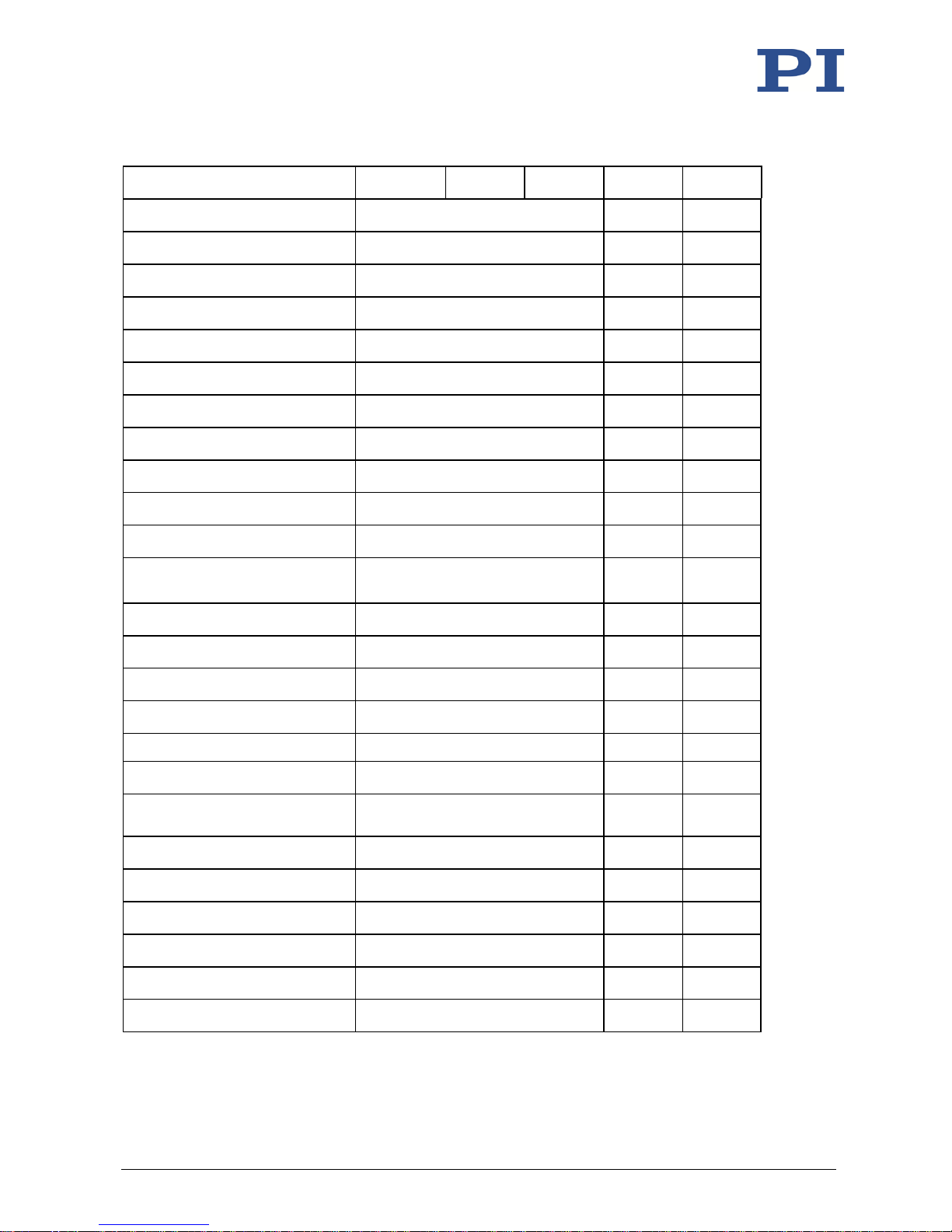
V-551.2D V-551.4D V-551.7D Unit Tolerance
Motion and positioning
Active axes
X
Travel range
60
130
230
mm
Pitch ±50 ±100 ±100 µrad typ.
Yaw ±50 µrad typ.
Straightness
±1
±1
±2
µm
typ.
Flatness ±2 µm typ.
Velocity 0.5* m/s max.
Mechanical properties
Load capacity in Z 150 N max.
Load capacity in Y 50 N max.
Moved mass
2.2
2.7
4.9
kg
Overall mass
4.2
5.5
9.7
kg
Linear guide Crossed roller bearing with anti-
creep system
Drive properties
Drive type PIMag® linear motor, ironless,
3-phase
Intermediate circuit voltage 110 ** V DC max.
10
Technical Data
Page 52
10 Technical Data
48 Version: 1.1.1 MP160E V-551 Linear Stage
V-551.2D V-551.4D V-551.7D Unit Tolerance
Peak force 180 N typ.
Nominal force
27 N typ.
Peak current, effective 10 A typ.
Nominal current, effective 1.5 A typ.
Force constant, effective 18 N/A typ.
Resistance per phase
3.15
Ω
typ.
Inductance per phase 0.9 mH typ.
Back EMF phase-phase 16 Vs/m max.
Pole pitch N-N
30
mm
Encoder options
Integrated sensor PIOne incremental linear encoder
Sensor signal
Sin/cos, 1 V peak-peak,
2 µm signal period
Sensor resolution 0.2 nm*** nm
Min. incremental motion
0.5
nm
typ.
Unidirectional repeatability 0.02 µm typ.
Bidirectional repeatability ±0.05 µm typ.
Travel range limit
Hall effect limit switches
Reference point switch
Encoder index
Reference point switch
repeatability
<1 µm
Miscellaneous
Operating temperature range 10 to 50 °C
Humidity
20 – 90% rel., not condensing
Material
Aluminum, black anodized
Motor connection HD Sub-D 26 (m)
Sensor connection Sub-D 15 (f)
* max. 0.2 m/s for V-551.xD when combined with the C-891
** 24 VDC with C-891.120200
*** interpolated
Page 53
10 Technical Data
V-551 Linear Stage MP160E Version: 1.1.1 49
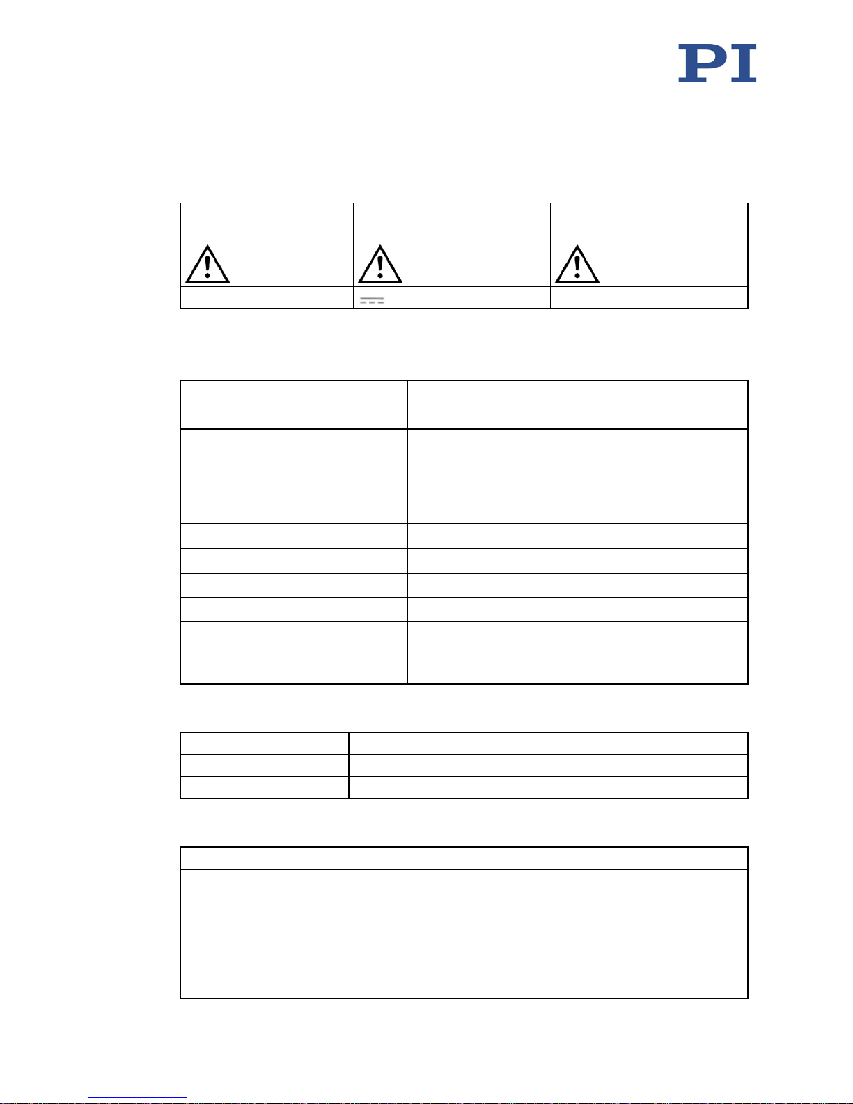
10.1.2 Maximum Ratings
The V-551 is designed for the following maximum ratings:
Maximum operating
voltage
Maximum operating frequency Maximum power consumption
110 V
650 W
10.1.3 Ambient Conditions and Classifications
The following ambient conditions and classifications for the V-551 must be observed:
Area of application For indoor use only
Maximum altitude 2000 m
Air pressure
1100 hPa to 795 hPa
(corresponds to roughly 825 Torr to 596 Torr)
Relative humidity Highest relative humidity 80% for temperatures up to
31 °C
Decreasing linearly to 50% relative humidity at 40 °C
Storage temperature
-20 °C to 60 °C
Transport temperature
-20 °C to 60 °C
Overvoltage category II
Protection class I
Degree of pollution
1
Degree of protection according to
IEC 60529
IP20
10.1.4 Reference Point Switch Specifications
Type Optical sensor
Supply voltage
+5 V/GND
Signal output
TTL level
10.1.5 Limit Switch Specifications
Type Magnetic (Hall effect) sensor
Supply voltage +5 V / ground
Signal output TTL level
Signal logic The signal level changes when passing the limit switch. The signal
logic is active low. That means:
Normal motor operation: high (+5 V)
Limit switch reached: low (0 V)
Page 54
10 Technical Data
50 Version: 1.1.1 MP160E V-551 Linear Stage
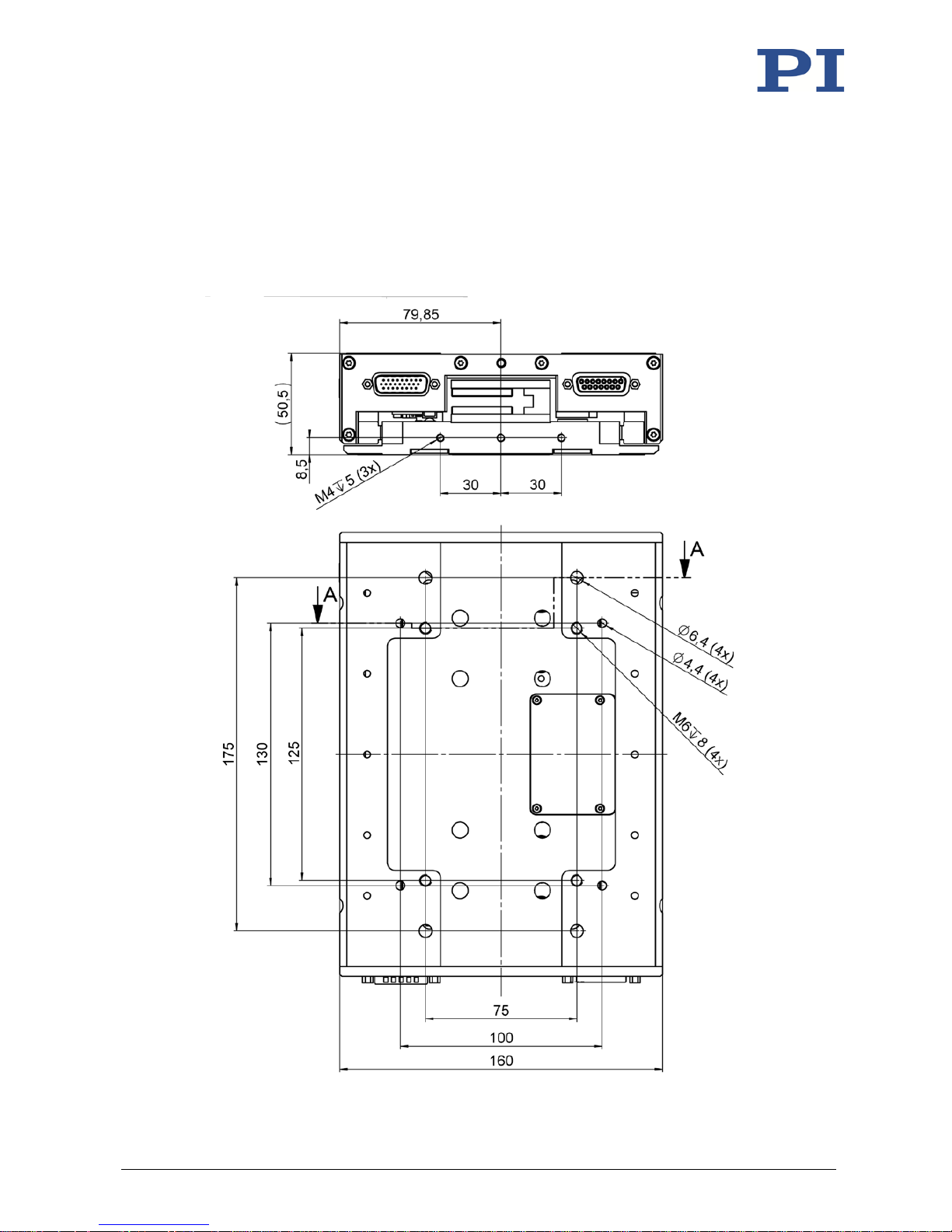
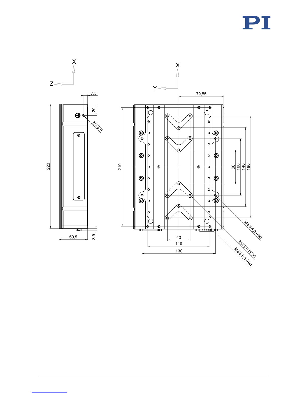
10.2 Dimensions
10.2.1 V-551.2D
Dimensions in mm. Note that the decimal points are separated by a comma in the drawings.
Motion platform in reference position.
Figure 15: Dimensions of the V-551.2D: Side view and bottom
Page 55
10 Technical Data
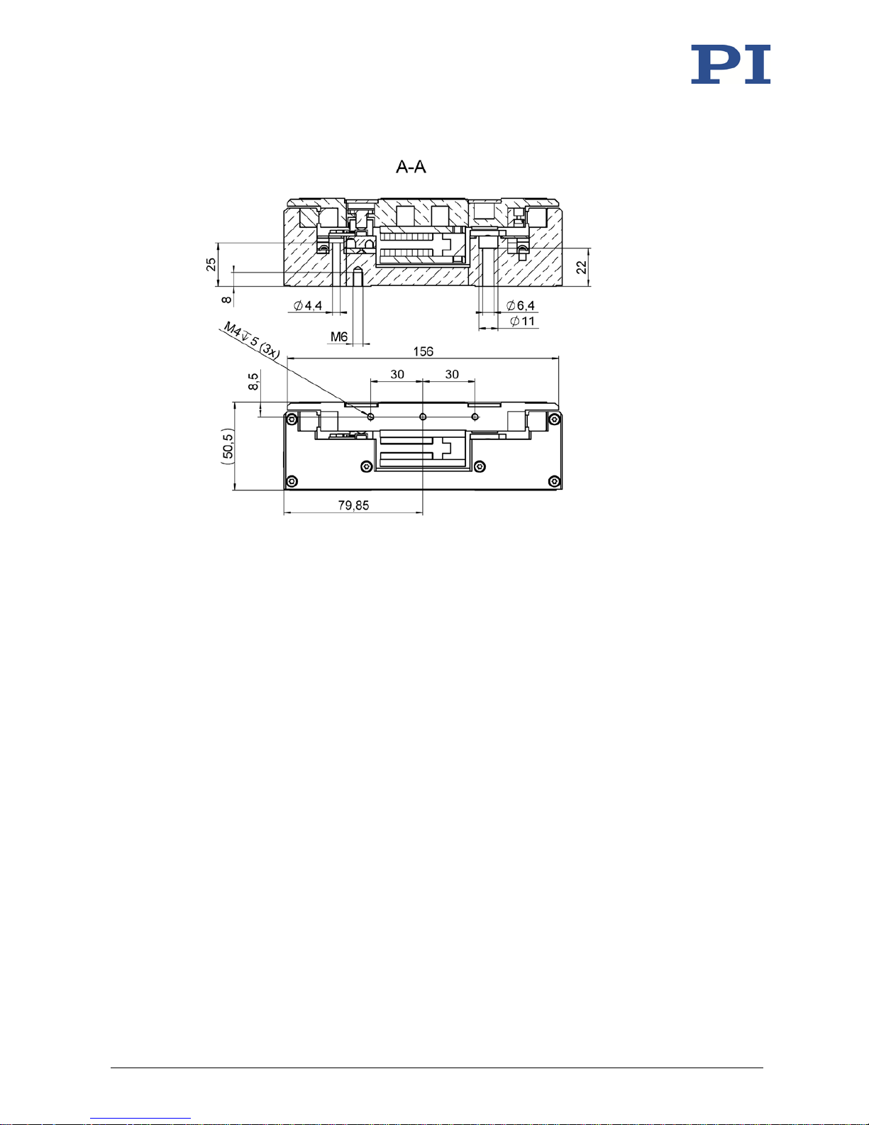
V-551 Linear Stage MP160E Version: 1.1.1 51
Figure 16: Dimensions of the V-551.2D: Section A and side view
Page 56
10 Technical Data
52 Version: 1.1.1 MP160E V-551 Linear Stage
Figure 17: Dimensions of the V-551.2D: Side view and top view
Page 57
10 Technical Data
V-551 Linear Stage MP160E Version: 1.1.1 53
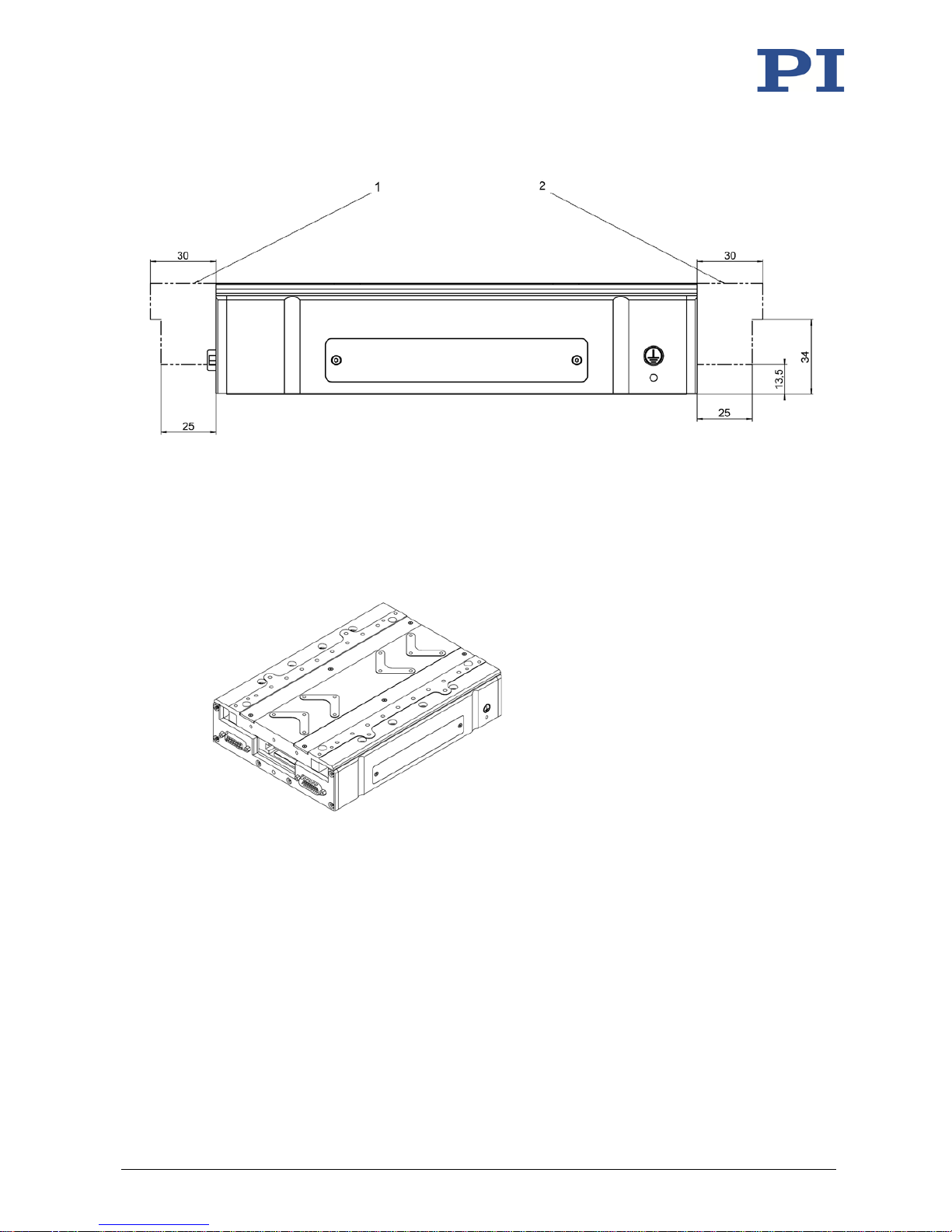
Figure 18: Stage in reference position (shown with solid line)
The dotted-dashed line shows the maximally extended motion platform
1 Maximum displacement of the platform at the negative end of the travel range
2 Maximum displacement of the platform at the positive end of the travel range
Figure 19: V-551.2D
Page 58
10 Technical Data
54 Version: 1.1.1 MP160E V-551 Linear Stage
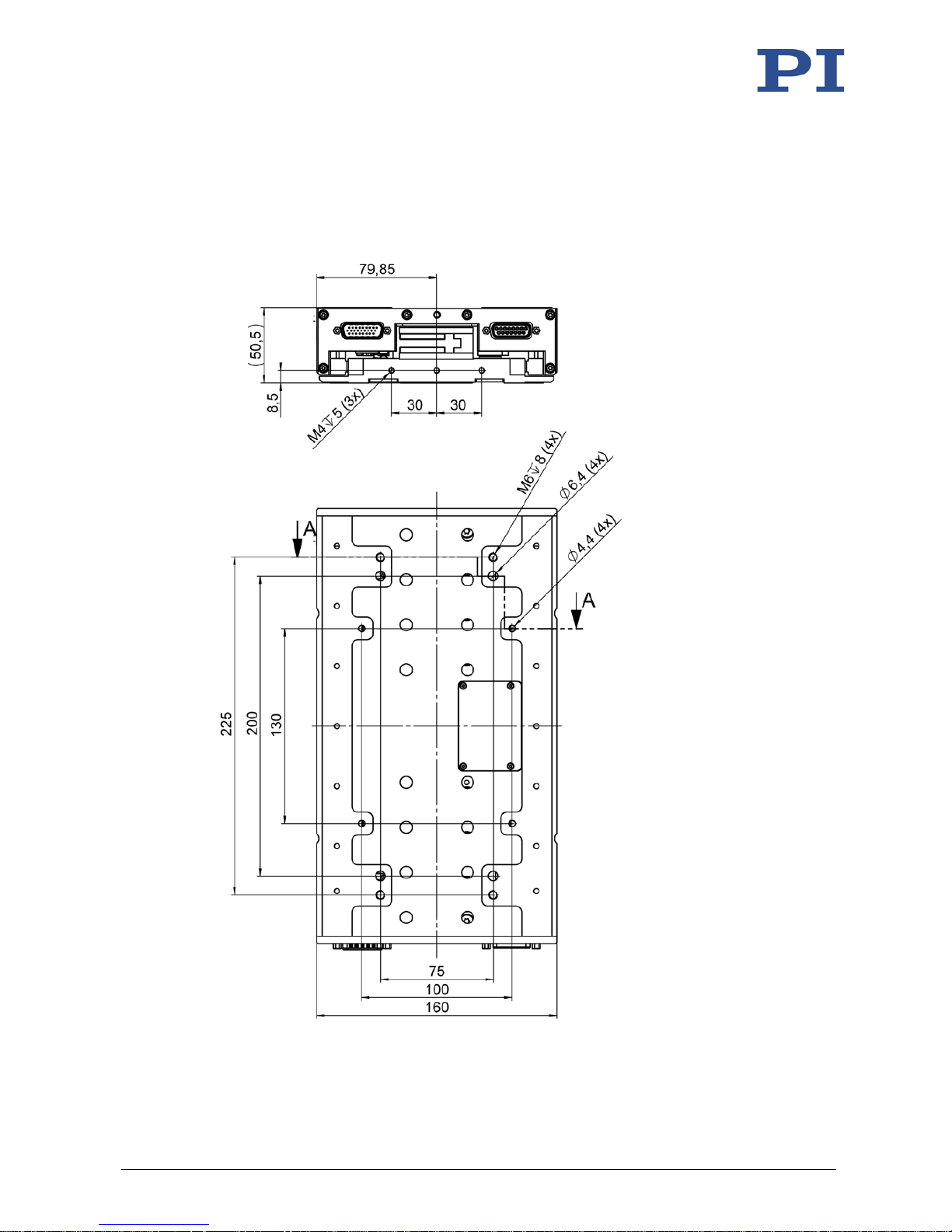
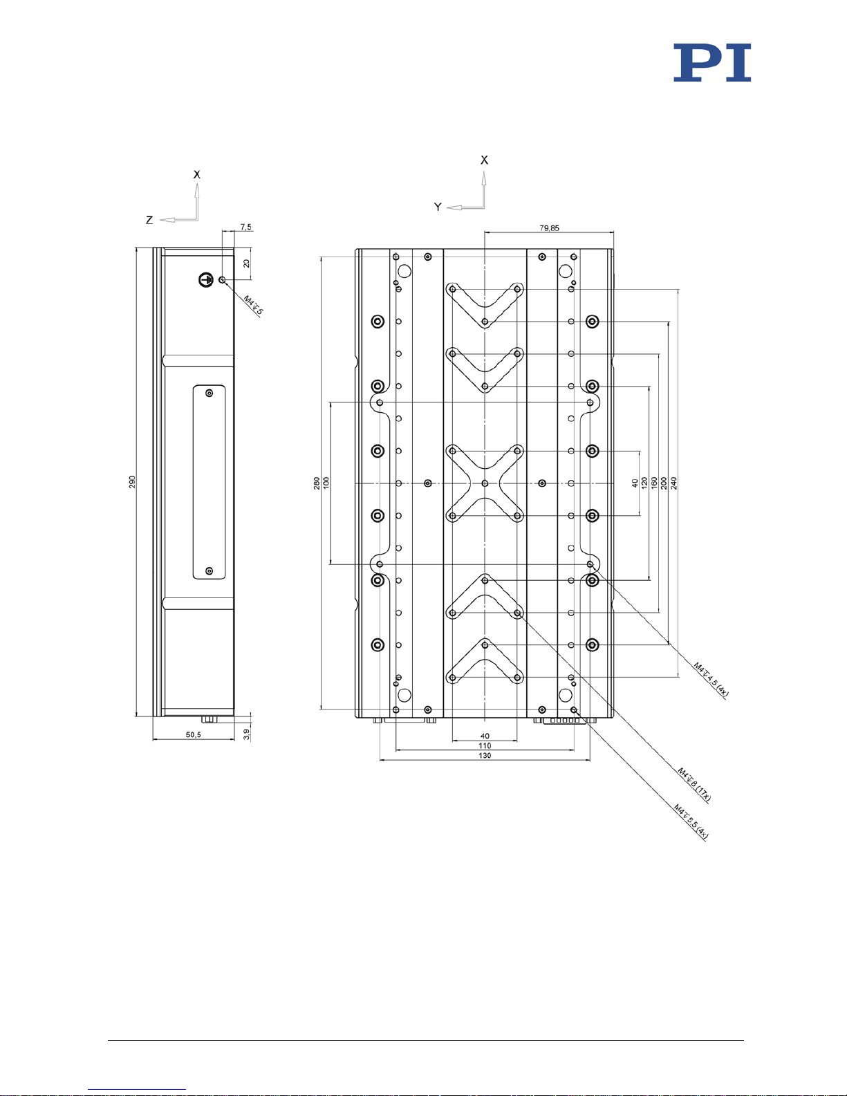
10.2.2 V-551.4D
Dimensions in mm. Note that the decimal points are separated by a comma in the drawings.
Motion platform in reference position.
Figure 20: Dimensions of the V-551.4D: Side view and bottom side
Page 59
10 Technical Data
V-551 Linear Stage MP160E Version: 1.1.1 55
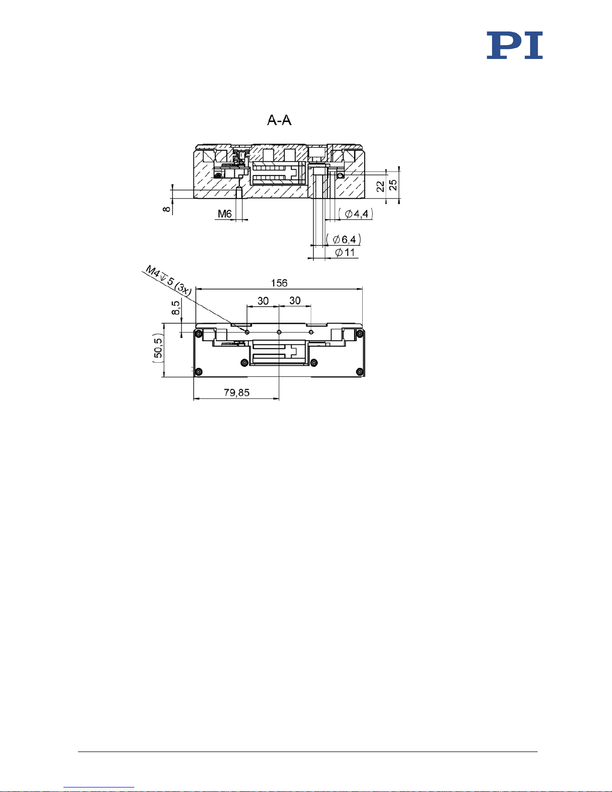
Figure 21: Dimensions of the V-551.4D: Section view A and side view
Page 60
10 Technical Data
56 Version: 1.1.1 MP160E V-551 Linear Stage
Figure 22: Dimensions of the V-551.4D: Side view and top view
Page 61
10 Technical Data
V-551 Linear Stage MP160E Version: 1.1.1 57
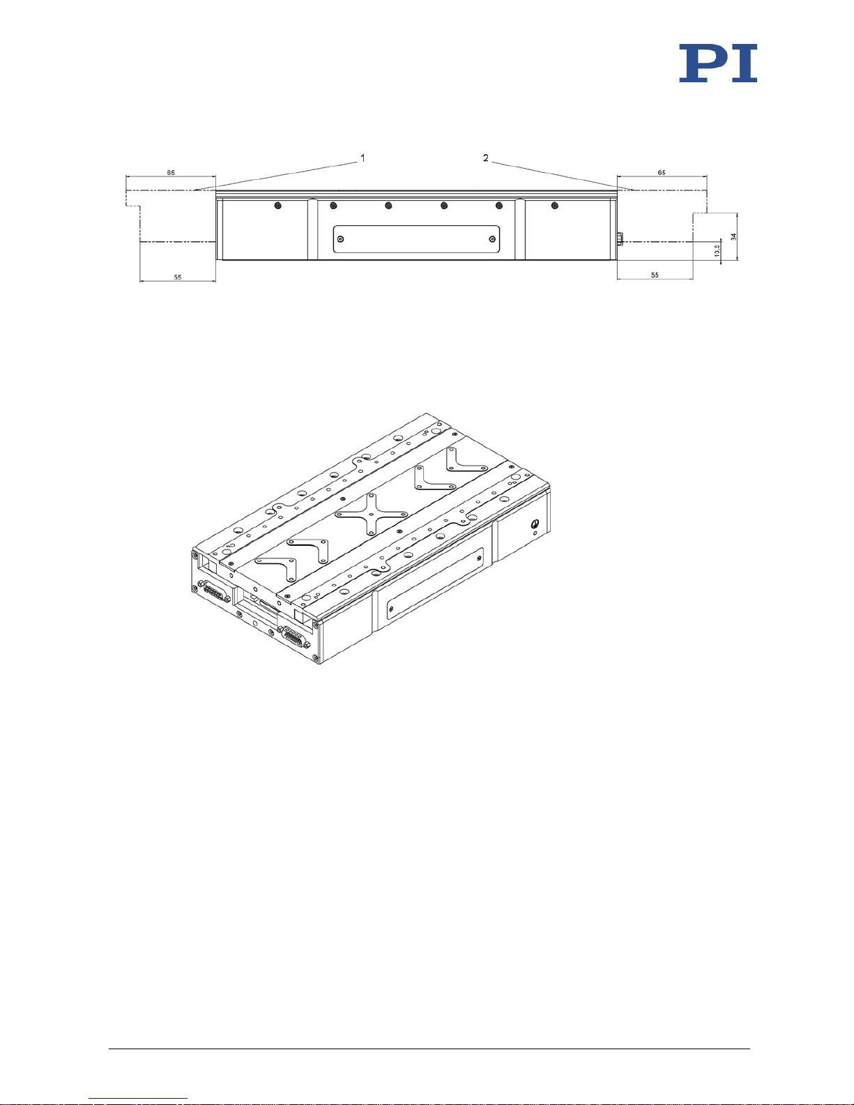
Figure 23: Stage in reference position (shown by solid line)
The dotted-dashed line shows the maximally extended motion platform
1 Maximum displacement of the platform at the positive end of the travel range
2 Maximum displacement of the platform at the negative end of the travel range
Figure 24: V-551.4D
Page 62
10 Technical Data
58 Version: 1.1.1 MP160E V-551 Linear Stage
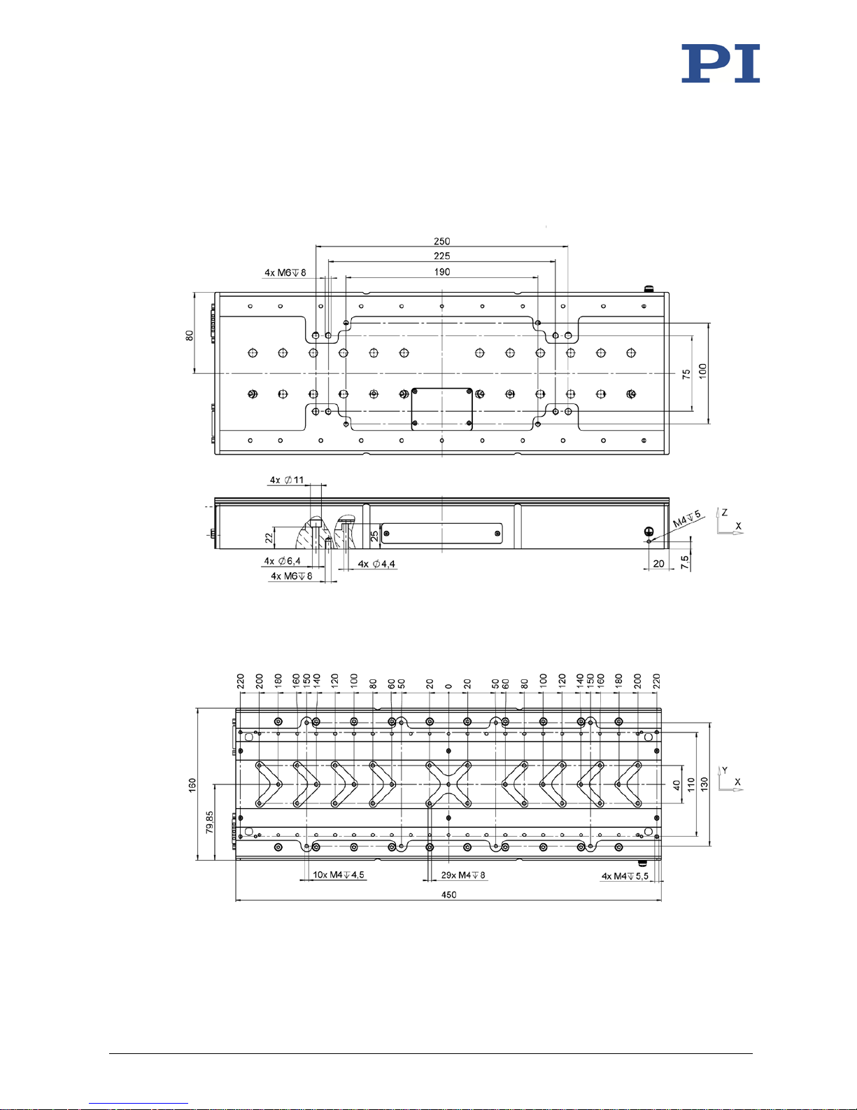
10.2.3 V-551.7D
Dimensions in mm. Note that the decimal points are separated by a comma in the drawings.
Motion platform in reference position.
Figure 25: Dimensions of the V-551.7D: Bottom view and side view
Figure 26: Dimensions of the V-551.7D: Top view
Page 63
10 Technical Data
V-551 Linear Stage MP160E Version: 1.1.1 59
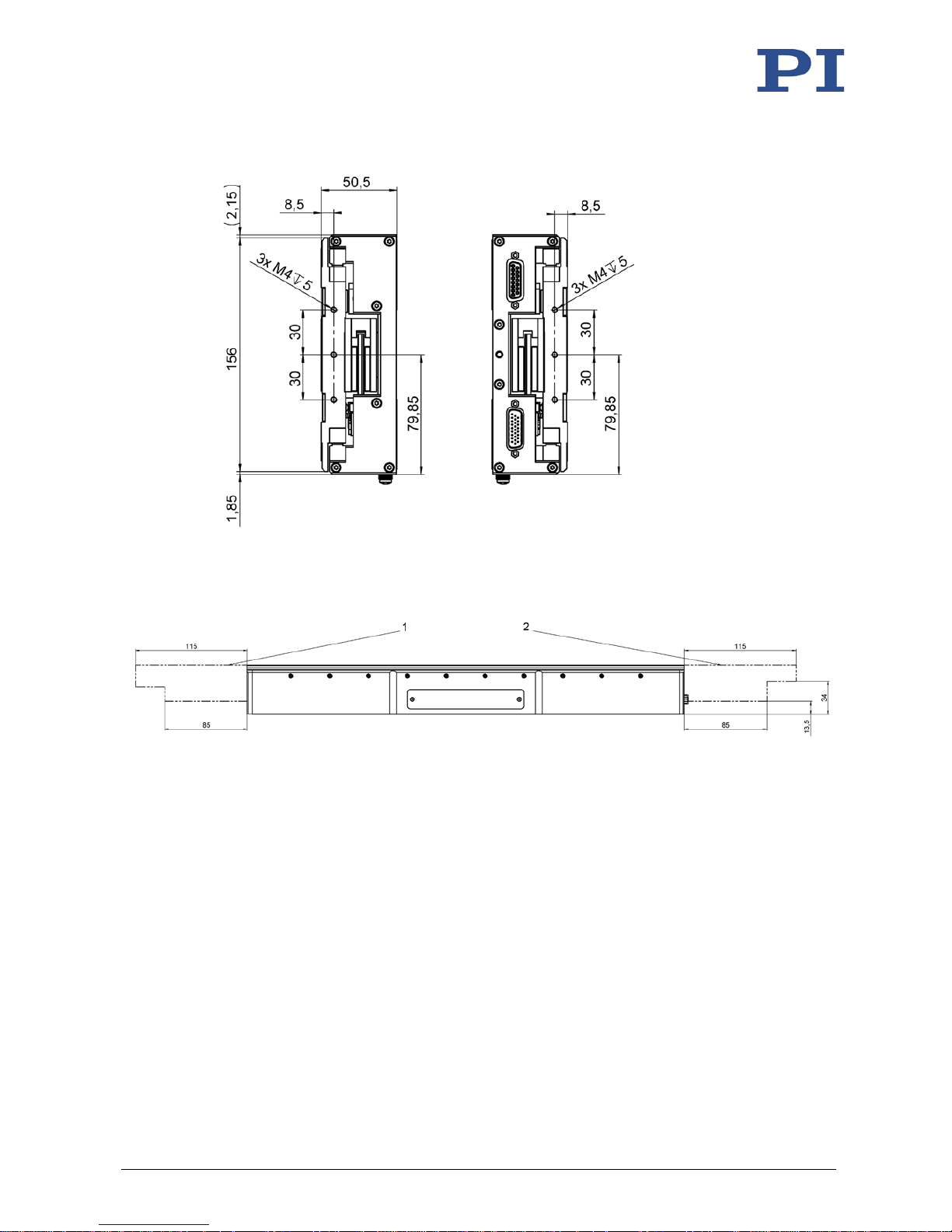
Figure 27: Dimensions of the V-551.7D: Side views
Figure 28: Stage in reference position (shown with solid line)
The dotted-dashed line shows the maximally extended motion platform
1 Maximum displacement of the platform at the positive end of the travel range
2 Maximum displacement of the platform at the negative end of the travel range
Page 64
10 Technical Data
60 Version: 1.1.1 MP160E V-551 Linear Stage
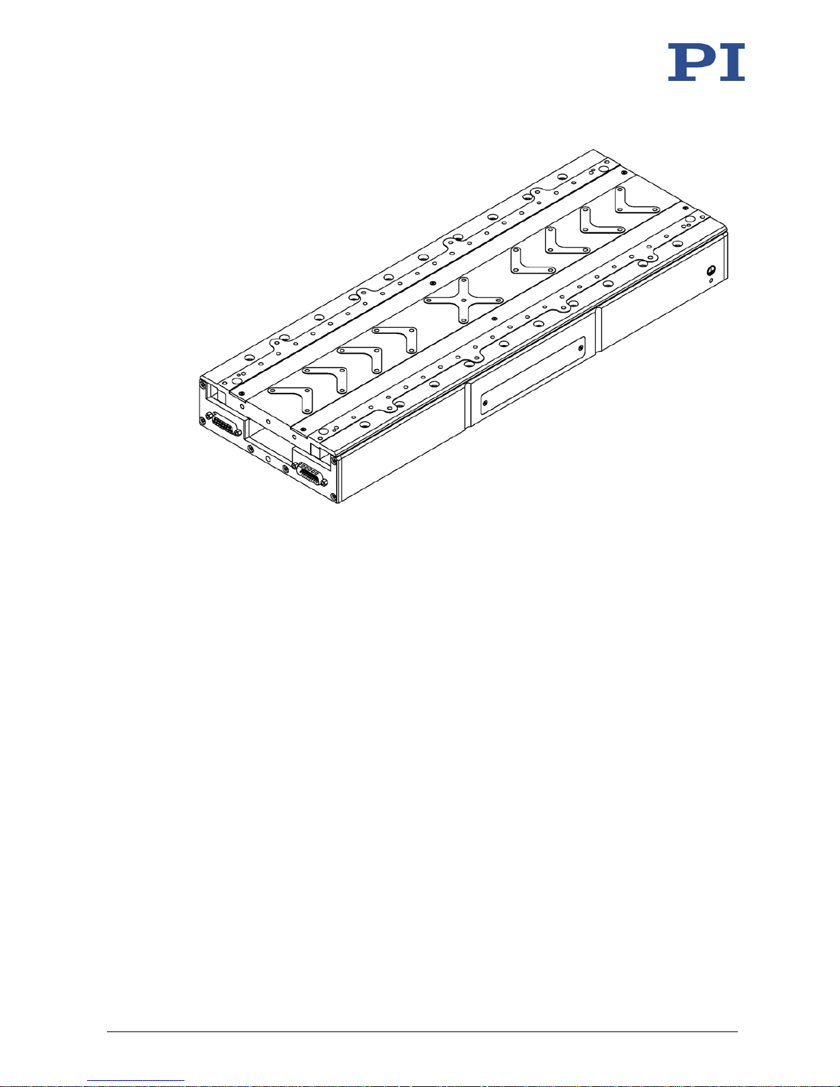
Figure 29: V-551.7D
Page 65
10 Technical Data
V-551 Linear Stage MP160E Version: 1.1.1 61
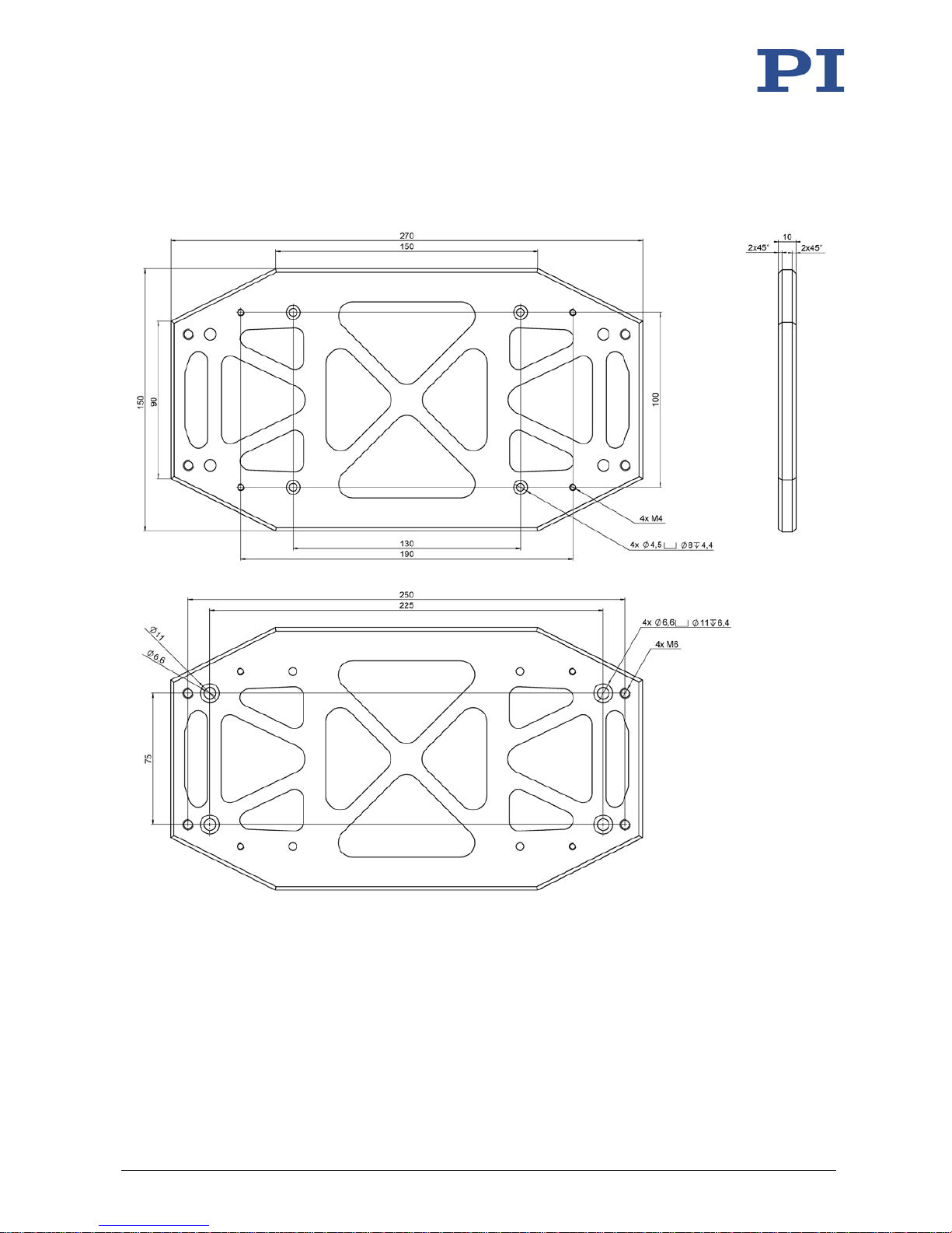
10.2.4 V-551.AP1 Adapter
Dimensions in mm. Note that the decimal points are separated by a comma in the drawings.
Figure 30: V-551.AP1 Adapter
Page 66
10 Technical Data
62 Version: 1.1.1 MP160E V-551 Linear Stage
10.3 Pin Assignment
10.3.1 Sensor
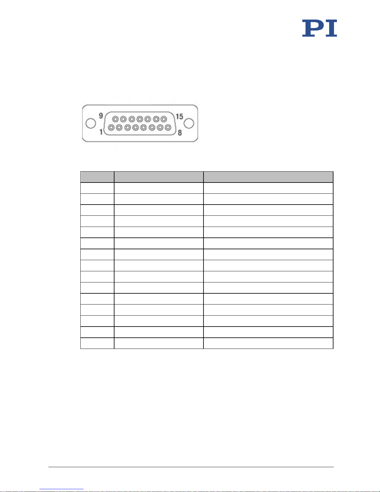
Figure 31: Sub-D 15 socket (f)
Pin Function Description
1
Vcc 5 V
Supply voltage for encoder
2 AGND Encoder ground
3 SIN+ Encoder sine+
4 SIN- Encoder sine-
5 GND Temperature sensor ground
6 COS+ Encoder cosine+
7 COS- Encoder cosine-
8 N-Limit Negative limit switch
9 PT100 PT100 temperature sensor
10 REF+ Reference+
11 Thermistor Protection against overheating
12 REF- Reference-
13 Reserved
14 GND Ground
15 P-Limit Positive limit switch
Page 67
10 Technical Data
V-551 Linear Stage MP160E Version: 1.1.1 63
10.3.2 Motor
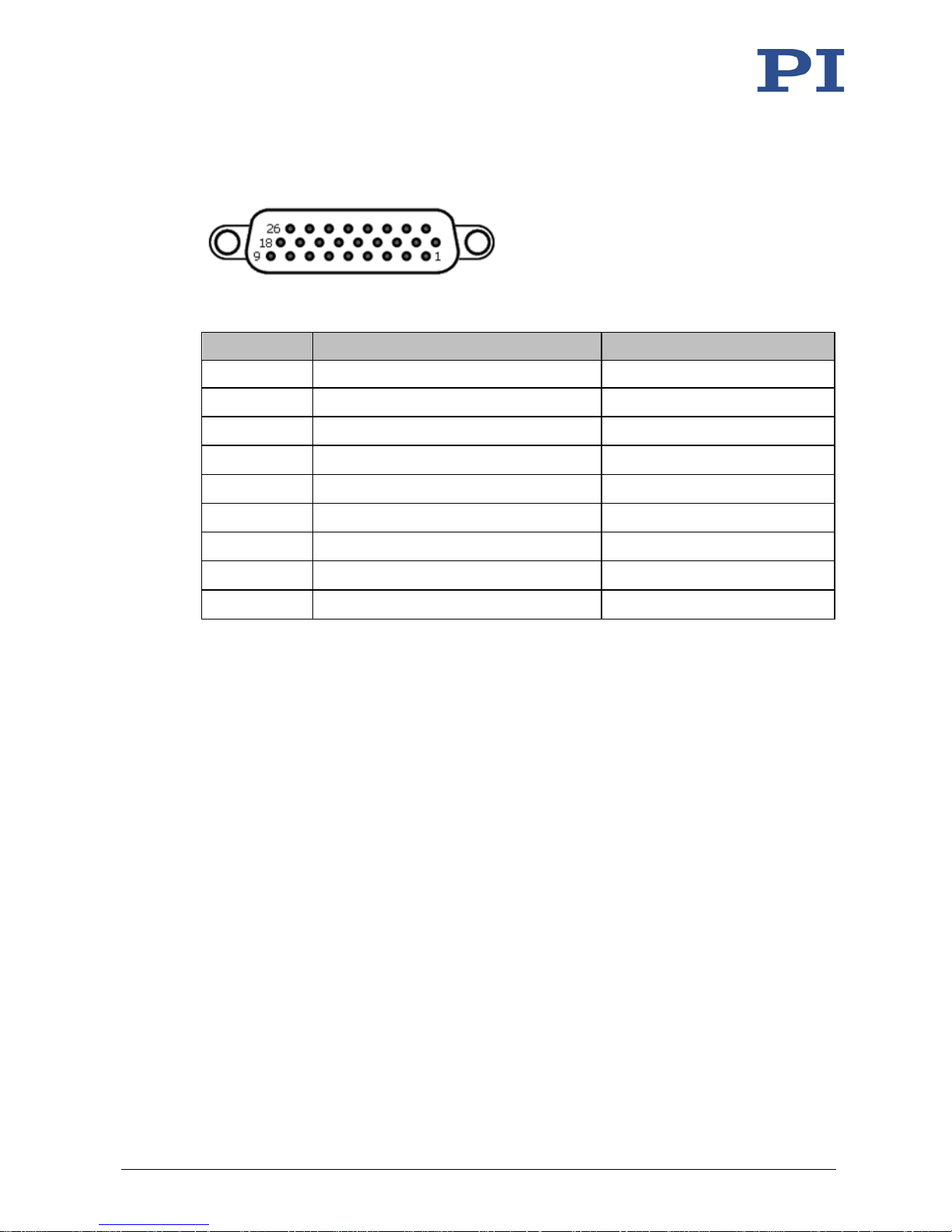
Figure 32: HD Sub-D 26 connector (m)
Pin Function* Description
1 Ph1 Phase 1
2 Ph1 Phase 1
3 Ph2 Phase 2
4 Ph2 Phase 2
5 Ph3 Phase 3
6 Ph3 Phase 3
7 - 24 - -
25 GND Ground
26 - -
* The "-" sign indicates that the corresponding pin has not been assigned.
Page 68

Page 69
11 Old Equipment Disposal
V-551 Linear Stage MP160E Version: 1.1.1 65
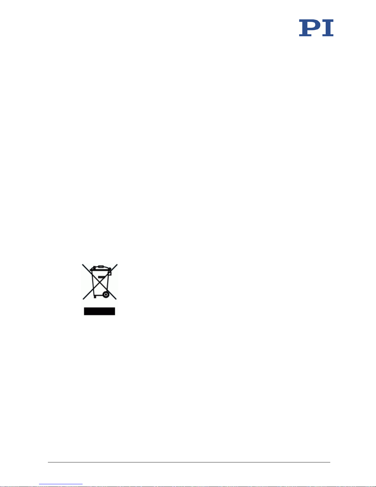
In accordance with EU law, electrical and electronic equipment may not be disposed of in EU
member states via the municipal residual waste.
Dispose of your old equipment according to international, national, and local rules and
regulations.
In order to fulfil its responsibility as the product manufacturer, Physik Instrumente (PI) GmbH &
Co. KG undertakes environmentally correct disposal of all old PI equipment made available on
the market after 13 August 2005 without charge.
Any old PI equipment can be sent free of charge to the following address:
Physik Instrumente (PI) GmbH & Co. KG
Auf der Roemerstr. 1
D-76228 Karlsruhe, Germany
11
Old Equipment Disposal
Page 70

Page 71
12 EU Declaration of Conformity
V-551 Linear Stage MP160E Version: 1.1.1 67
For the V-551, an EU Declaration of Conformity has been issued in accordance with the
following European directives:
EMC Directive
RoHS Directive
The applied standards certifying the conformity are listed below.
EMC: EN 61326-1
Safety: EN 61010-1
RoHS: EN 50581
12
EU Declaration of Conformity
 Loading...