

Page 1
User Manual
KSch/CBo, 2018-11-13
P725T0010, valid for P-725
Physik Instrumente (PI ) GmbH & Co. KG, Auf der Roemerstr. 1, 76228 Karlsruhe/Germany
Phone +49 721 4846-0, Fax +49 721 4846-1019, Email [email protected], www.pi.ws
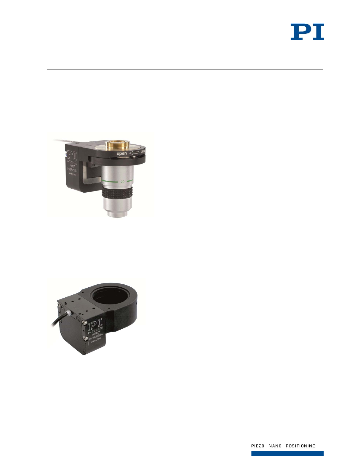
P-725 PIFOC Long-Travel Objective Scanner
P-725.xDD PIFOC High-Dynamics Piezo Scanner
Page 2

Page 2 / 25
2018-11-13
P725T0010, valid for P-725
Physik Instrumente (PI ) GmbH & Co. KG, Auf der Roemerstr. 1, 76228 Karlsruhe/Germany
Phone +49 721 4846-0, Fax +49 721 4846-1019, Email [email protected], www.pi.ws
Contents
About this Document ..................................................................................................................... 3
Symbols and Typographic Conventions ........................................................................................ 3
Figures.......................................................................................................................................... 3
Safety ................................................................................................................................... 3
Intended Use ................................................................................................................................ 3
Safety Precautions ........................................................................................................................ 4
Product Description ........................................................................................................... 5
Model Overview ............................................................................................................................ 5
Product View................................................................................................................................. 6
Product Labeling ........................................................................................................................... 7
Scope of Delivery .......................................................................................................................... 7
Accessories .................................................................................................................................. 8
Suitable Electronics ...................................................................................................................... 9
Installation........................................................................................................................... 9
Connecting the P-725 to the Protective Earth Conductor .............................................................. 9
Affixing the P-725 to the Microscope ........................................................................................... 10
Installing the Objective ................................................................................................................ 12
Startup and Operation ...................................................................................................... 13
General Notes on Startup and Operation .................................................................................... 13
Starting Up and Operating the P-725 .......................................................................................... 14
Discharging the P-725 ...................................................................................................... 14
Maintenance ...................................................................................................................... 15
Cleaning the P-725 ..................................................................................................................... 15
Customer Service ............................................................................................................. 15
Technical Data .................................................................................................................. 16
P-725 PIFOC Long-Travel Objective Scanner............................................................................. 16
P-725.xDD Fast PIFOC High-Dynamics Piezo Scanner .............................................................. 18
Dimensions ....................................................................................................................... 19
P-725.xCD, P-725.xCL, P-725.x0L ............................................................................................. 19
P-725.xCA .................................................................................................................................. 20
P-725.xDD .................................................................................................................................. 21
Pin Assignments .............................................................................................................. 22
P-725.xCL, P-725.x0L ................................................................................................................. 22
P-725.SDD ................................................................................................................................. 23
P-725.xCD, P-725.xCA, P-725.CDD ........................................................................................... 24
Maximum Ratings ............................................................................................................. 24
Ambient Conditions and Classifications ........................................................................ 25
Old Equipment Disposal .................................................................................................. 25
Page 3
Page 3 / 25
2018-11-13
P725T0010, valid for P-725
Physik Instrumente (PI ) GmbH & Co. KG, Auf der Roemerstr. 1, 76228 Karlsruhe/Germany
Phone +49 721 4846-0, Fax +49 721 4846-1019, Email [email protected], www.pi.ws
About this Document
Symbols and Typographic Conventions
The following symbols and typographic conventions are used in this user manual:
CAUTION
Dangerous situation
If not avoided, the dangerous situation will result in minor injury.
Actions to take to avoid the situation.
NOTICE
Dangerous situation
If not avoided, the dangerous situation will result in damage to the equipment.
Actions to take to avoid the situation.
INFORMATION
Information for easier handling, tricks, tips, etc.
Figures
For better understandability, the colors, proportions, and degree of detail in illustrations can deviate
from the actual circumstances. Photographic illustrations may also differ and must not be seen as
guaranteed properties.
Safety
Intended Use
The P-725 is a laboratory device as defined by DIN EN 61010-1. It is intended to be used in interior
spaces and in an environment which is free of dirt, oil and lubricants.
Based on its design and realization, the P-725 is intended for positioning and shifting microscope
objectives in one axis.
The P-725 Z drive can be mounted horizontally or vertically. The specifications refer to a vertically
mounted Z drive.
The intended use of the P-725 is only possible in a completely assembled and connected state. The
P-725 must be operated with a suitable controller that is available from PI. The controller is not
included in the scope of delivery of the P-725.
Page 4
Page 4 / 25
2018-11-13
P725T0010, valid for P-725
Physik Instrumente (PI ) GmbH & Co. KG, Auf der Roemerstr. 1, 76228 Karlsruhe/Germany
Phone +49 721 4846-0, Fax +49 721 4846-1019, Email [email protected], www.pi.ws
Safety Precautions
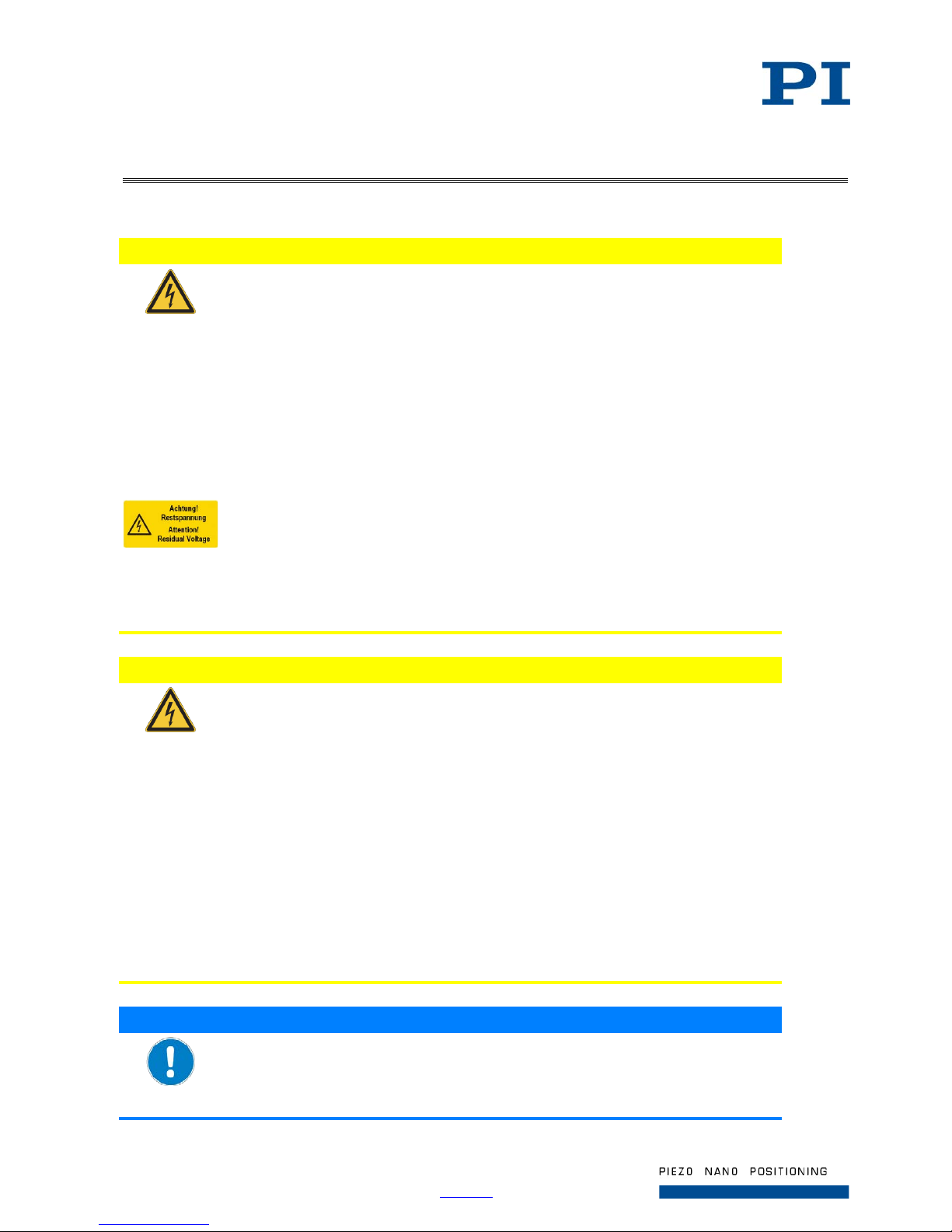
CAUTION
Dangerous voltage and residual c harge on piezo actuators!
The P-725 is driven by piezo actuators. Temperature changes and compressive
stresses can induce charges in piezo actuators. After being disconnected from the
electronics, piezo actuators can also stay charged for several hours. Touching or
short-circuiting the contacts in the connector of the P-725 can lead to minor injuries.
In addition, the piezo actuators can be destroyed by an abrupt contraction.
Do not open the P-725.
Discharge the piezo actuators before installation:
Connect the piezo actuator to the switched-off PI controller.
Do not pull out the connector from the electronics during operation.
For P-725 with sub-D connector:
Touching the contacts in the connector can lead to an electric shock (max.
120 V DC) and minor injuries.
Do not touch the contacts in the connector.
Secure the connector of the piezo actuator with screws against being pulled out
of the controller.
CAUTION
Risk of electric shock if the protective earth conductor is not connected!
If a protective earth conductor is not or not properly connected, dangerous touch
voltages can occur and there is a risk of electric shock. In the case of malfunction or
failure of the system, touching the P-725 can result in minor injuries.
Connect the P-725 to a protective earth conductor before startup.
Do not remove the protective earth conductor during operation.
Use electrically conductive materials (e.g., screws and flat washers) for mounting
the protective earth conductor.
Make sure that the contact resistance is <0.1 Ω at 25 A at all connection points
relevant for mounting the protective earth conductor.
If the protective earth conductor has to be temporarily removed (e.g., for
modifications), reconnect the P-725 to the protective earth conductor before
starting it up again.
NOTICE
Unsuitable cables!
Unsuitable cables can damage the electronics.
Only use cables from PI for connecting the P-725 to the electronics.
Page 5
Page 5 / 25
2018-11-13
P725T0010, valid for P-725
Physik Instrumente (PI ) GmbH & Co. KG, Auf der Roemerstr. 1, 76228 Karlsruhe/Germany
Phone +49 721 4846-0, Fax +49 721 4846-1019, Email [email protected], www.pi.ws
INFORMATION
Extended cables can affect the performance of the P-725.
Do not use cable extensions. If you need longer cables, contact our customer
service department (p. 15).
Product Description
Model Overview
The models of the P-725 differ in terms of:
Travel range
Sensor
Connector
Thread adapter
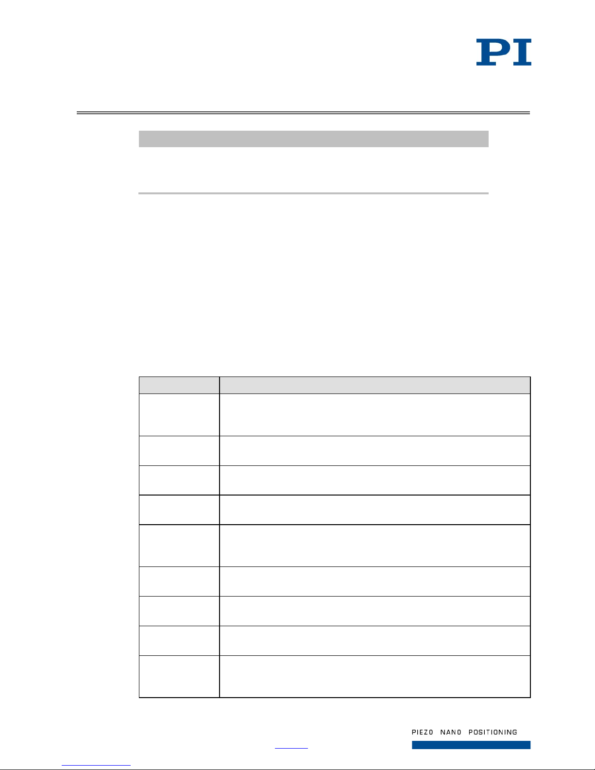
Product number Description
P-725.1CA PIFOC piezo nanofocusing Z drive for long scanning ranges, 100 µm,
capacitive sensors, sub-D connector, for large aperture QuickLock thread
adapters
P-725.1CD PIFOC piezo nanofocusing Z drive for long scanning ranges, 100 µm,
capacitive sensors, sub-D connector, for QuickLock thread adapters
P-725.1CL PIFOC piezo nanofocusing Z drive for long scanning ranges, 100 µm,
capacitive sensors, LEMO connectors, for QuickLock thread adapters
P-725.10L PIFOC piezo nanofocusing Z drive for long scanning ranges, 150 µm,
open-loop, LEMO connectors, for QuickLock thread adapters
P-725.2CA PIFOC piezo nanofocusing Z drive for long scanning ranges, 250 µm,
capacitive sensors, sub-D connector, for large aperture QuickLock thread
adapters
P-725.2CD PIFOC piezo nanofocusing Z drive for long scanning ranges, 250 µm,
capacitive sensors, sub-D connector, for QuickLock thread adapters
P-725.2CL PIFOC piezo nanofocusing Z drive for long scanning ranges, 250 µm,
capacitive sensors, LEMO connectors, for QuickLock thread adapters
P-725.20L PIFOC piezo nanofocusing Z drive for long scanning ranges, 330 µm,
open-loop, LEMO connectors, for QuickLock thread adapters
P-725.4CA PIFOC piezo nanofocusing Z drive for long scanning ranges, 400 µm,
capacitive sensors, sub-D connector, for large aperture QuickLock thread
adapters
Page 6
Page 6 / 25
2018-11-13
P725T0010, valid for P-725
Physik Instrumente (PI ) GmbH & Co. KG, Auf der Roemerstr. 1, 76228 Karlsruhe/Germany
Phone +49 721 4846-0, Fax +49 721 4846-1019, Email [email protected], www.pi.ws
Product number Description
P-725.4CD PIFOC piezo nanofocusing Z drive for long scanning ranges, 400 µm,
capacitive sensors, sub-D connector, for QuickLock thread adapters
P-725.4CL PIFOC piezo nanofocusing Z drive for long scanning ranges, 400 µm,
capacitive sensors, LEMO connectors, for QuickLock thread adapters
P-725.40L PIFOC piezo nanofocusing Z drive for long scanning ranges, 460 µm,
open-loop, LEMO connectors, for QuickLock thread adapters
P-725.CDD Fast PIFOC piezo nanofocusing Z drive, 18 µm, capacitive sensor, sub-D
connector, for QuickLock thread adapters
P-725.SDD Fast PIFOC piezo nanofocusing Z drive, 18 µm, SGS sensor, LEMO
connectors, for QuickLock thread adapters
Product View
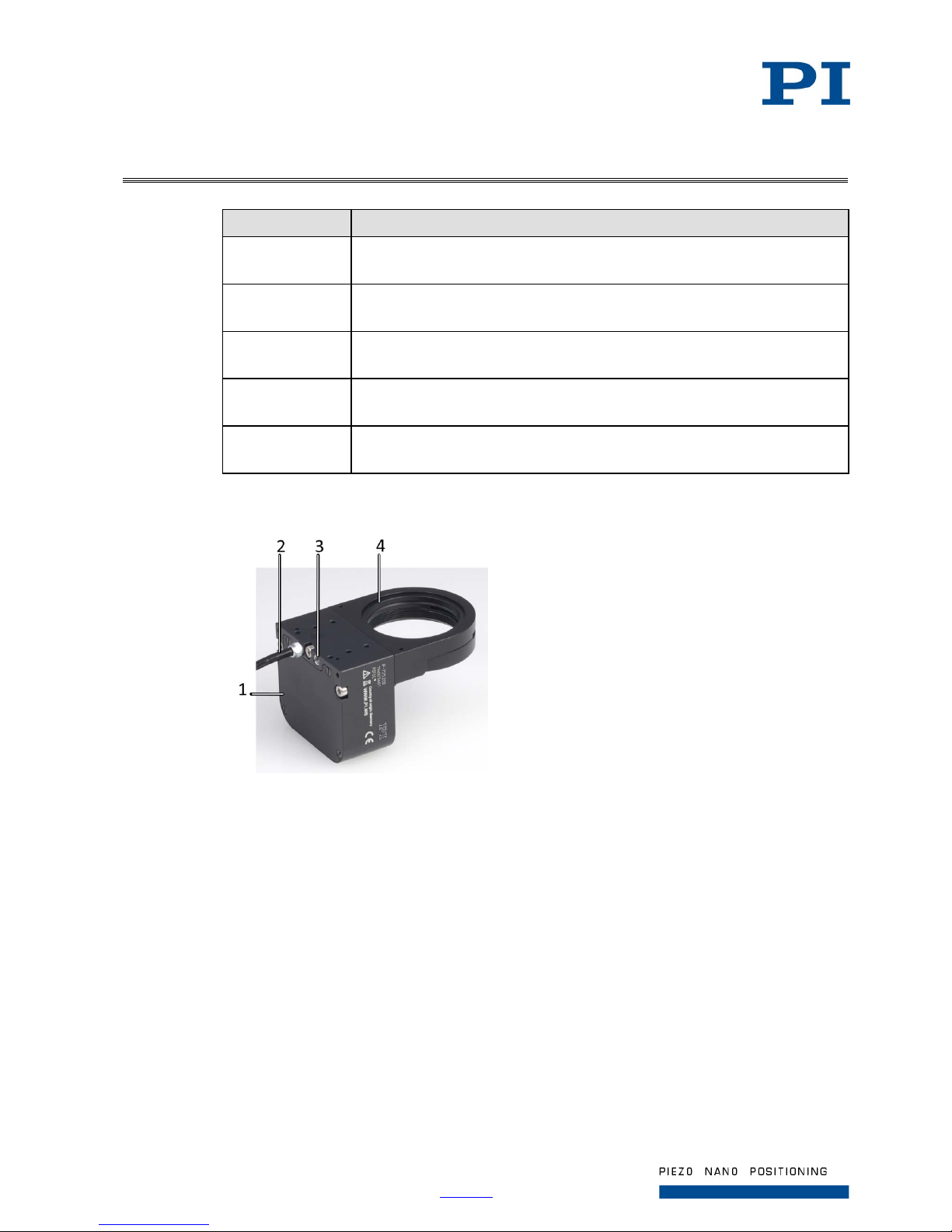
Figure 1: Components of the Z drive, example of a P-725.2CD, here without symbol for protective
earth connection
1 Base body
2 Cable exit
3 Protective earth connection
4 Threaded aperture
Page 7
Page 7 / 25
2018-11-13
P725T0010, valid for P-725
Physik Instrumente (PI ) GmbH & Co. KG, Auf der Roemerstr. 1, 76228 Karlsruhe/Germany
Phone +49 721 4846-0, Fax +49 721 4846-1019, Email [email protected], www.pi.ws
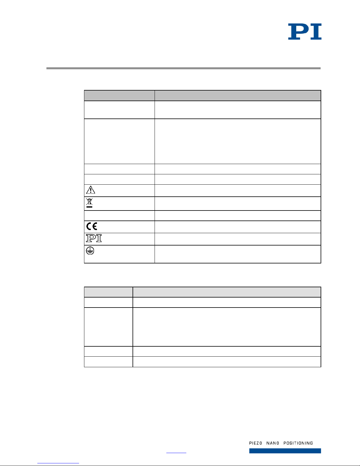
Product Labeling
Labeling Description
P-725.2CD Product number (example), the digits after the period refer to the
model
117003601 Serial number (example), individual for each P-725
Meaning of the places (counting from left):
1 = internal information
2 and 3 = manufacturing year
4 to 9 = consecutive numbers
PIFOC Brand name
Country of origin: Germany Country of origin
Warning sign "Observe manual!"
Old equipment disposal (p. 25)
WWW.PI.WS Manufacturer's address (website)
CE conformity mark
Manufacturer's logo
Symbol for the protective earth conductor (p. 9), marks the
protective earth connection of the P-725
Scope of Delivery
Product number Description
P-725 PIFOC piezo nanofocusing Z drive according to order (p. 5)
000036450 M4 screw set for protective earth, consisting of:
1 M4x8 flat-head screw with cross recess, ISO 7045
2 safety washers
2 flat washers
PZ240EK Short instructions for piezo positioning systems
P721T0002 Technical note for QuickLock thread option
Page 8
Page 8 / 25
2018-11-13
P725T0010, valid for P-725
Physik Instrumente (PI ) GmbH & Co. KG, Auf der Roemerstr. 1, 76228 Karlsruhe/Germany
Phone +49 721 4846-0, Fax +49 721 4846-1019, Email [email protected], www.pi.ws
Accessories
Extension tubes
Product number Description
P-721.90Q Extension tube, 12.5 mm, thread W0.8 x 1/36’’
P-721.91Q Extension tube, 12.5 mm, thread M25 x 1/36’’
P-721.92Q Extension tube, 12.5 mm, thread M26 x 1/36’’
P-721.93Q Extension tube, 12.5 mm, thread M27 x 1/36’’
P-721.94Q Extension tube, 12.5 mm, thread M28 x 1/36’’
P-721.95Q Extension tube, 12.5 mm, thread M32 x 1/36’’
P-721.96Q Extension tube, 12.5 mm, thread M26 x 1/36’’
P-721.98Q Extension tube, 12.5 mm, thread M19 x 1/36’’
QuickLock thread adapters
Product number Description
Only for P-725.xxD / .xxL
P-721.02Q QuickLock thread adapter, M26 x 0.75 mm, Ø 21 mm
P-721.03Q QuickLock thread adapter, M27 x 0.75 mm, Ø 21 mm
P-721.04Q QuickLock thread adapter, M28 x 0.75 mm, Ø 21 mm
P-721.05Q QuickLock thread adapter, M32 x 0.75 mm, Ø 21 mm
P-721.06Q QuickLock thread adapter, M26 x 1/36’’, Ø 21 mm
P-721.08Q QuickLock thread adapter, M19 x 0.75 mm, Ø 14 mm
P-721.11Q QuickLock thread adapter, M25 x 0.75 mm, Ø 21 mm
P-721.12Q QuickLock thread adapter, W0.8 x 1/36’’, Ø 14 mm
Only for P-725.xCA
P-721.02A QuickLock thread adapter for large apertures, M26 x 0.75 mm, Ø 23 mm
P-721.03A QuickLock thread adapter for large apertures, M27 x 0.75 mm, Ø 24 mm
P-721.04A QuickLock thread adapter for large apertures, M28 x 0.75 mm, Ø 25 mm
P-721.05A QuickLock thread adapter for large apertures, M32 x 0.75 mm, Ø 29 mm
P-721.06A QuickLock thread adapter for large apertures, M26 x 1/36’’, Ø 23 mm
P-721.11A QuickLock thread adapter for large apertures, M25 x 0.75 mm, Ø 22 mm
Adapter cables
Product number Description
P-895.1DLC Adapter cable Sub-D 7W2 (f) to LEMO for piezo actuator nanopositioning
systems with capacitive sensors, 1 channel, 0.3 m. Fits controller s wit h
LEMO connectors (1× voltage, 2× sensor).
P-895.1LDC Adapter cable LEMO to sub-D 7W2 (m) for piezo actuator nanopositioning
systems with capacitive sensors, 1 channel, 0.3 m. Fits motion controllers
with Sub-D 7W2 (f) socket.
Page 9
Page 9 / 25
2018-11-13
P725T0010, valid for P-725
Physik Instrumente (PI ) GmbH & Co. KG, Auf der Roemerstr. 1, 76228 Karlsruhe/Germany
Phone +49 721 4846-0, Fax +49 721 4846-1019, Email [email protected], www.pi.ws
Suitable Electronics
Model /
Mechanics
Model / Electronics
Capacitive sensor,
sub-D connection:
P-725.xCD
P-725.xCA
P-725.CDD
E-621 controller module
E-625 servo controller, bench-top
E-665 display servo controller, with digital interface, bench-top
E-754 single-channel digital controller
E-709 single-channel digital controller
Capacitive sensor,
LEMO connection:
P-725.xCL
E-610 servo controller / amplifier
E-500 modular piezo controller system with E-505 high-performance
amplifier module and E-509 controller
Strain gauge
sensor, LEMO
connection:
P-725.SDD
E-610 servo controller / amplifier
E-625 servo controller, bench-top
E-665 display servo controller, with digital interface, bench-top
E-709 single-channel digital controller
No sensor,
LEMO connection:
P-725.x0L
E-500 modular piezo controller system with E-505 high-performance
amplifier module
E-610.00 amplifier
Installation
Connecting the P-725 to the Protective Earth Conductor
INFORMATION
Observe the applicable standards for mounting the protective earth conductor.
The P-725 is equipped with an M4 hole for fastening the protective earth conductor. This hole is
marked with the protective earth conductor symbol (see " Dimensions", p. 19).
Requirements
You have read and understood the safety precautions (p. 3).
The P-725 is not connected to the electronics.
Tools and accessories
Suitable protective earth conductor: Cross-sectional area of the cable ≥0.75 mm
2
Supplied M4 protective earth screw set (p. 7) for connecting the protective earth conductor
Suitable screwdriver
Page 10
Page 10 / 25
2018-11-13
P725T0010, valid for P-725
Physik Instrumente (PI ) GmbH & Co. KG, Auf der Roemerstr. 1, 76228 Karlsruhe/Germany
Phone +49 721 4846-0, Fax +49 721 4846-1019, Email [email protected], www.pi.ws
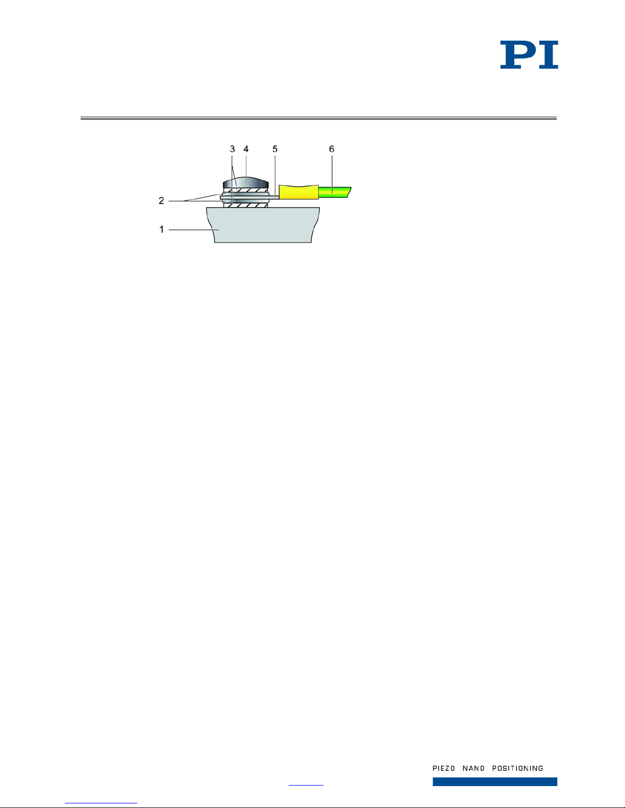
Figure 2: Mounting of the protective earth conductor (profile view)
1 Base body of the P-725
2 Flat washer
3 Safety washer
4 Screw
5 Cable lug
6 Protective earth conductor
Connecting the P-725 to the protective earth conductor
1. If nec ess ary, fasten a suitable cable lug to the protective earth conductor.
2. Use t he M4 screw (together with the washers and self-locking washers) to affix the cable lug
of the protective earth conductor to the protective earth connection of the P-725 as shown in
the profile view.
3. Tighten the M4 screw with a torque of 1.2 Nm to 1.5 Nm.
4. Make sur e that the contact resistance at all connection points relevant for mounting the
protective earth conductor is <0.1 Ω at 25 A.
Affixing the P-725 to the Microscope
The P-725 can be affixed to the microscope in one of the following ways:
Installation using the QuickLock thread adapter (p. 10)
Optional: Installation using the mounting holes in the base body of the P-725 (p. 11).
With this mounting option, you only need the objective insert of the QuickLock thread adapter.
Installing the P-725 Using the QuickLock Thread Adapter
Requirements
You have read and understood the safety precautions (p. 3).
Tools and accessories
P721T0002 technical note for PIFOC QuickLock thread option (p. 7)
QuickLock thread adapter (p. 8) (not included)
Suitable tools
Page 11
Page 11 / 25
2018-11-13
P725T0010, valid for P-725
Physik Instrumente (PI ) GmbH & Co. KG, Auf der Roemerstr. 1, 76228 Karlsruhe/Germany
Phone +49 721 4846-0, Fax +49 721 4846-1019, Email [email protected], www.pi.ws
Installing the P-725 using the QuickLock thread adapter
Install the P-725 as described in the P721T0002 technical note for PIFOC QuickLock thread
option (p. 7).
Installing the P-725 Using the Mounting Holes (Optional)
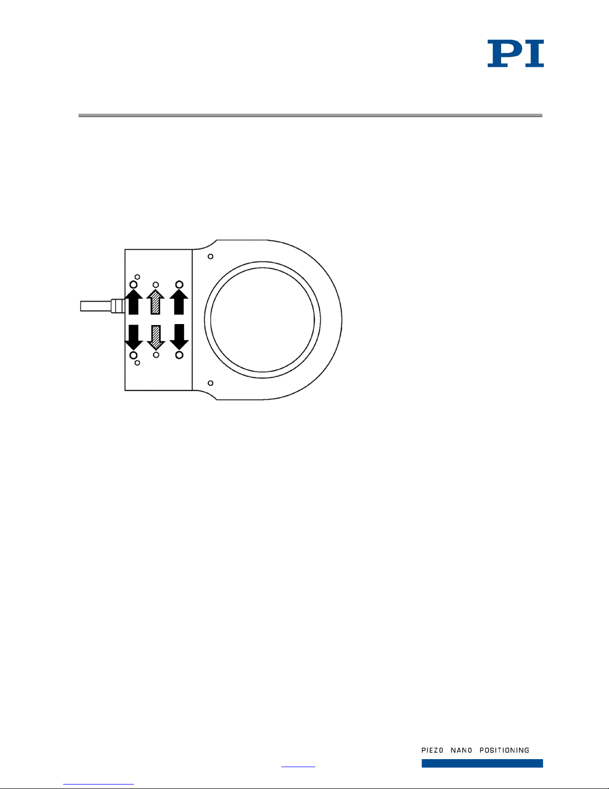
The figure serves as an example and can differ from your model.
Figure 3: P-725 (example view): Mounting holes (black arrows) and locating holes (hatched arrows) in the base
body of the P-725
Requirements
You have read and understood the safety precautions (p. 3).
Tools and accessories
P721T0002 technical note for PIFOC QuickLock thread option (p. 7)
QuickLock thread adapter (p. 8) (not included)
Note that you only need the objective insert of the QuickLock thread adapter.
Four M2.5 screws of suitable length (p. 19) for screwing the P-725 onto a microscope
Optional: Two suitable locating pins (p. 19) for alignment of the P-725
Suitable tools
Installing the P-725 using the mounting holes (optional)
1. Screw the objective insert into the P-725 as described in the P721T0002 technical note for
PIFOC QuickLock thread option (p. 7).
2. Optional: Align the P-725 with the microscope using suitable locating pins and the locating
holes in the base body of the P-725 (see Figure 3 above).
3. Affix the P-725 to the microscope using four suitable M2.5 screws and the mounting holes in
the base body of the P-725 (see Figure 3 above).
Page 12
Page 12 / 25
2018-11-13
P725T0010, valid for P-725
Physik Instrumente (PI ) GmbH & Co. KG, Auf der Roemerstr. 1, 76228 Karlsruhe/Germany
Phone +49 721 4846-0, Fax +49 721 4846-1019, Email [email protected], www.pi.ws
Installing the Objective
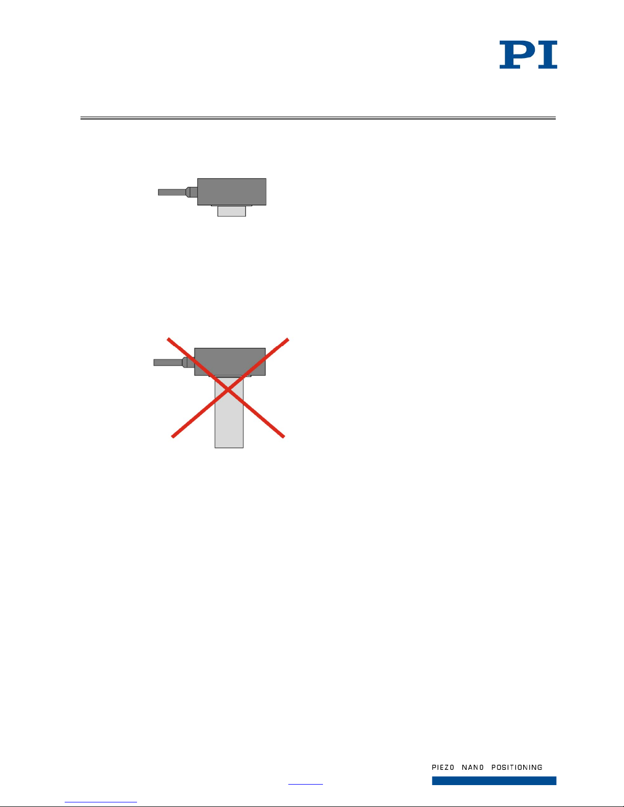
Correct:
Figure 4: Center of load close to aperture
Incorrect:
Mounting the load incorrectly causes high strain on the flexure guides in the Z drive, hig h torques and
the danger of oscillations.
Figure 5: Center of load far below the aperture
Requirements
You have read and understood the safety precautions (p. 3).
You have affixed the P-725 to the microscope (p. 10).
Tools and accessories
P721T0002 technical note for PIFOC QuickLock thread option (p. 7)
QuickLock thread adapter (p. 8) (not included)
Objective to be installed (not included)
Suitable tools
Installing the objective
Screw the objective into the P-725. See the P721T0002 technical note (p. 7) for details.
Pay attention to a maximum torque of 0.6 Nm.
Page 13
Page 13 / 25
2018-11-13
P725T0010, valid for P-725
Physik Instrumente (PI ) GmbH & Co. KG, Auf der Roemerstr. 1, 76228 Karlsruhe/Germany
Phone +49 721 4846-0, Fax +49 721 4846-1019, Email [email protected], www.pi.ws
Startup and Operation
General Notes on Startup and Operation
NOTICE
Destruction of the piezo actuator by ele ctric flashovers!
The use of the P-725 in environments that increase the electrical conductivity can
lead to the destruction of the piezo actuator by electric flashovers. Electric flashovers
can be caused by moisture, high humidity, liquids and conductive materials such as
metal dust. In addition, electric flashovers can also occur in certain air pressure
ranges due to the increased conductivity of the air.
Avoid operating the P-725 in environments that can increase the electric
conductivity.
Only operate the P-725 within the permissible ambient conditions and
classifications (p. 25).
NOTICE
Destruction of the piezo actuator by continuously high voltage!
The constant application of high voltage to piezo actuators can lead to leakage
currents and flashovers that destroy the ceramic.
If the P-725 is not used, but the controller is to remain switched on to ensure
temperature stability:
Set the piezo voltage to 0 V on the controller.
NOTICE
Uncontrolled oscillation!
Oscillations can cause irreparable damage to the P-725. Oscillations are indicated by
a humming and can result from the following causes:
The load and/or dynamics of operation differ too much from the calibration
settings.
The P-725 is operated near its resonant frequency.
If you notice oscillations, stop the P-725 immediately.
Page 14
Page 14 / 25
2018-11-13
P725T0010, valid for P-725
Physik Instrumente (PI ) GmbH & Co. KG, Auf der Roemerstr. 1, 76228 Karlsruhe/Germany
Phone +49 721 4846-0, Fax +49 721 4846-1019, Email [email protected], www.pi.ws
INFORMATION
Systems are calibrated at the factory to achieve optimum performance. Replacing
the system components will cause a loss in performance when Z drives without
ID chip are used, or whose ID chip does not contain any calibration data, or when
Z drives with LEMO connectors or analog controllers are used.
Only P -725.xxD and P-725.xCA Z drives are equipped with an ID chip.
Note the assignment of the Z drive axis to the controller channel, which is given
by the calibration label of the piezo servo controller.
For systems without ID chip:
If the piezo servo controller or the Z drive has to be replaced, recalibrate the axis
displacement (see controller manual) or contact our customer service
department (p. 15).
Starting Up and Operating the P-725
Requirements
You have read and understood the safety precautions (p. 3).
You have read and understood the general notes on startup and operation (p. 13).
Starting up and operating the P-725
Follow the instructions in the user manual of the piezo controller used for startup and
operation of the P-725.
Discharging the P-725
The P-725 must be discharged before demounting. Demounting is necessary e.g., before cleaning or
transporting the P-725 as well as for modifications
Discharging a P-725 that is connected to the controller
In closed-loop operation:
1. Switch off the servo mode on the controller.
2. Set t he piezo voltage to 0 V on the controller.
In open-loop operation:
Set the piezo voltage to 0 V on the controller.
Discharging a P-725 that is not connected to the controller
Connect the P-725 to the switched-off PI controller for 10 seconds.
Page 15
Page 15 / 25
2018-11-13
P725T0010, valid for P-725
Physik Instrumente (PI ) GmbH & Co. KG, Auf der Roemerstr. 1, 76228 Karlsruhe/Germany
Phone +49 721 4846-0, Fax +49 721 4846-1019, Email [email protected], www.pi.ws
Maintenance
NOTICE
Misalignment from loosening screws on the base body!
The P-725 is maintenance-free and precisely aligned.
Only loosen screws according to the instructions in this manual.
Do not open the P-725.
Cleaning the P-725
Requirements
You have discharged the piezo actuators of the P-725.
You have disconnected the P-725 from the controller.
Cleaning the P-725
Clean the surface of the P-725 with a cloth that is lightly dampened with a mild cleanser or
disinfectant (e.g., ethanol or isopropyl alcohol).
Do not do any ultrasonic cleaning.
Customer Service
For inquiries and orders, contact your PI sales engineer or send us an email ([email protected]).
If you have questions concerning your system, have the following information ready:
− Product and serial numbers of all products in the system
− Firmware version of the controller (if present)
− Version of the driver or the software (if present)
− Operating system on the PC (if present)
If possible: Take photographs or make videos of your system that can be sent to our customer
service department if requested.
The latest versions of the user manuals are available for download on our website (www.pi.ws
).
Page 16
Page 16 / 25
2018-11-13
P725T0010, valid for P-725
Physik Instrumente (PI ) GmbH & Co. KG, Auf der Roemerstr. 1, 76228 Karlsruhe/Germany
Phone +49 721 4846-0, Fax +49 721 4846-1019, Email [email protected], www.pi.ws
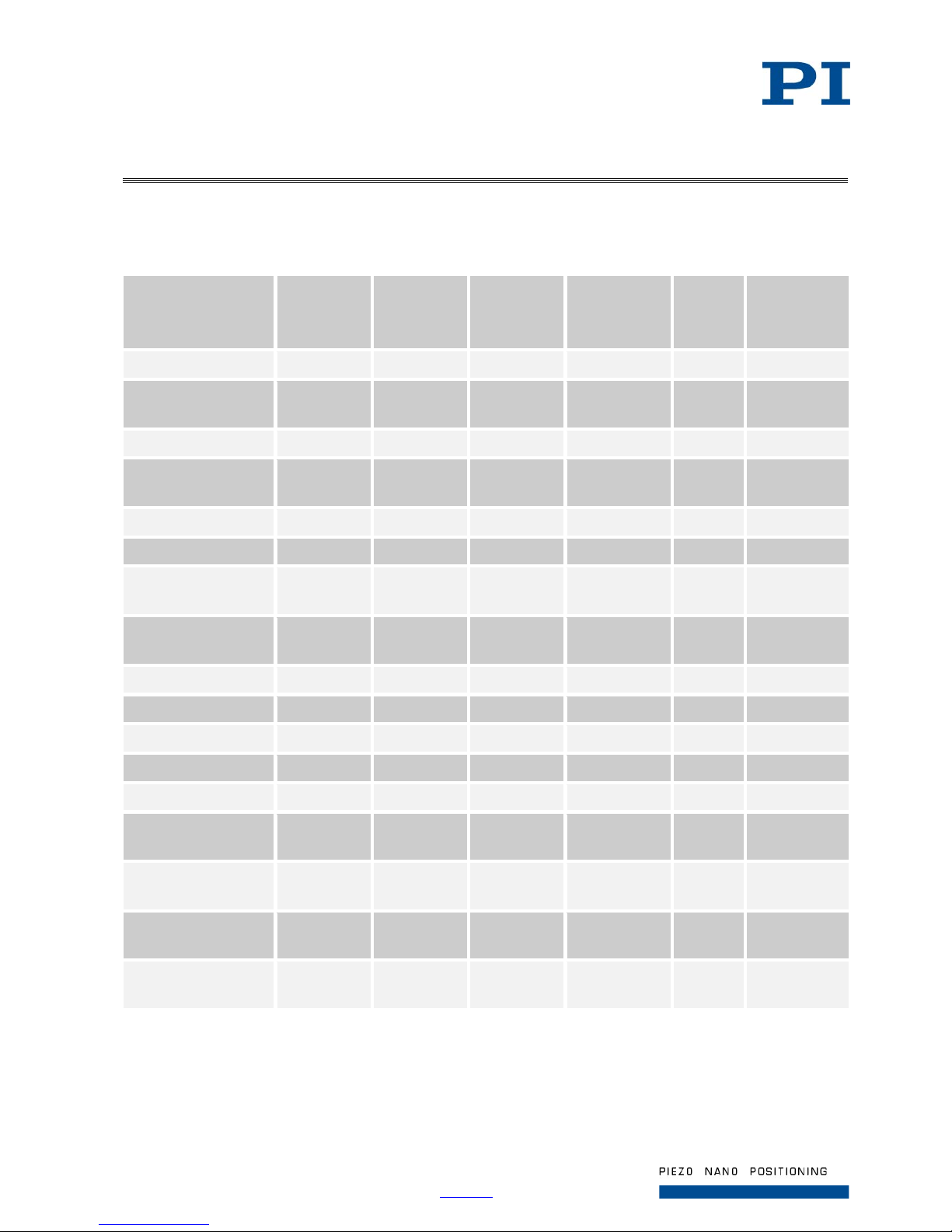
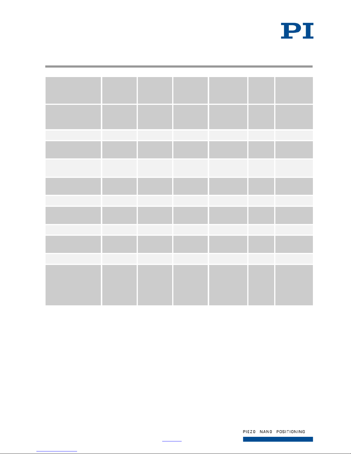
Technical Data
P-725 PIFOC Long-Travel Objective Scanner
Model P-725.1CL
P-725.1CD
P-725.1CA
P-725.2CL
P-725.2CD
P-725.2CA
P-725.4CL
P-725.4CD
P-725.4CA
P-725.x0L
open-loop
version
Unit Tolerance
Active axes Z Z Z Z
Motion and
positioning
Integrated sensor Capacitive Capacitive Capacitive Open-loop travel,
-20 to +120V
150 330 460 as P-725.xCL µm min. (+20 %/
-0 %)
Closed-loop travel 100 250 400 - µm calibrated
Open-loop resolution 0.3 0.4 0.5 as P-725.xCL nm typ.
Closed-loop
resolution
0.65 0.75 1.25 - nm typ.
Linearity, closedloop
0.03 0.03 0.03 - % typ.
Repeatability ±5 ±5 ±5 - nm typ.
Runout θX 1 6 10 as P-725.xCL µrad typ.
Runout θY 20 45 45 as P-725.xCL µrad typ.
Crosstalk in X 20 20 60 as P-725.xCL nm typ.
Crosstalk in Y 20 40 60 as P-725.xCL nm typ.
Mechanical
properties
Stiffness in motion
direction
0.23 0.17 0.12 as P-725.xCL N/µm ±20 %
Unloaded resonant
frequency
470 330 230 as P-725.xCL Hz ±20 %
Resonant frequency
at 150 g
185 140 120 as P-725.xCL Hz ±20 %
Page 17
Page 17 / 25
2018-11-13
P725T0010, valid for P-725
Physik Instrumente (PI ) GmbH & Co. KG, Auf der Roemerstr. 1, 76228 Karlsruhe/Germany
Phone +49 721 4846-0, Fax +49 721 4846-1019, Email [email protected], www.pi.ws
Model P-725.1CL
P-725.1CD
P-725.1CA
P-725.2CL
P-725.2CD
P-725.2CA
P-725.4CL
P-725.4CD
P-725.4CA
P-725.x0L
open-loop
version
Unit Tolerance
Push/pull force
capacity in motion
direction
100 / 20 100 / 20 100 / 20 as P-725.xCL N max.
Drive properties
Ceramic type PICMA®
P-885
PICMA®
P-885
PICMA®
P-885
as P-725.xCL
Electrical
capacitance
4.2 6.2 6.2 as P-725.xCL µF ±20 %
Dynamic operating
current coefficient
5.2 3.1 1.9 as P-725.xCL µA / (Hz
× µm)
±20 %
Miscellaneous
Operating
temperature range*
-20 to 80 -20 to 80 -20 to 80 -20 to 80 °C
Material Aluminum Aluminum Aluminum Aluminum
Max. objective
diameter
39 39 39 39 mm
Mass 0.215 0.23 0.23 as P-725.xCL kg ±5 %
Sensor / voltage
connection
CL-version:
LEMO
Others:
Sub-D 7W2
(m)
CL-version:
LEMO
Others:
Sub-D 7W2
(m)
CL-version:
LEMO
Others:
Sub-D 7W2
(m)
LEMO (no
sensor)
*Specifications assured from 17° C to 23° C. The piezo scanner has to be recalibrated for temperatures outside
this range.
Page 18
Page 18 / 25
2018-11-13
P725T0010, valid for P-725
Physik Instrumente (PI ) GmbH & Co. KG, Auf der Roemerstr. 1, 76228 Karlsruhe/Germany
Phone +49 721 4846-0, Fax +49 721 4846-1019, Email [email protected], www.pi.ws
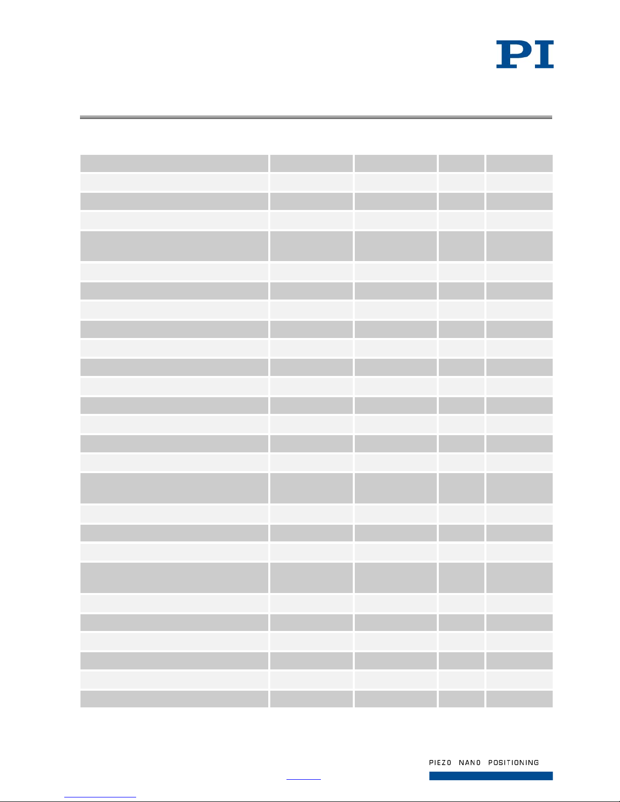
P-725.xDD Fast PIFOC High-Dynamics Piezo Scanner
P-725.CDD P-725.SDD Unit Tolerance
Active axes Z Z
Motion and positioning
Integrated sensor Capacitive SGS
Open-loop travel, -20 to +120 V 18 18 µm min. (20 % /
-0 %)
Closed-loop travel 18 18 µm
Open-loop resolution 0.2 0.2 nm typ.
Closed-loop resolution 0.2 0.2 nm typ.
Closed-loop linearit y error 0.04 0.5 % typ.
Repeatability ±1.5 ±5 nm typ.
Runout θ
X
, θY 2 2 µrad typ.
Crosstalk in X, Y 150 150 nm typ.
Mechanical properties
Stiffness in motion direction 1.5 1.5 N/µm ±20 %
Resonant frequency, no load 1180 1180 Hz ±20 %
Resonant frequency, under load, at 200 g 450 450 Hz ±20 %
Push / pull force capacity in motion
direction
100 / 20 100 / 20 N max.
Drive properties
Ceramic type PICMA® P-887 PICMA® P-887
Electrical capacitance 3.1 3.1 µF ±20 %
Dynamic operating current coefficient 19.4 19.4 µA / (Hz
× µm)
±20 %
Miscellaneous
Operating temperature range* -20 to 80 -20 to 80 °C
Material Aluminum Aluminum
Mass 0.21 0.2 kg ±5 %
Cable length 1.5 1.5 m ±10 mm
Sensor / voltage connection Sub-D 7W2 (m) LEMO
*Specifications assured from 17 °C to 23 °C. The piezo scanner has to be recalibrated for temperatures outside
this range.
Page 19
Page 19 / 25
2018-11-13
P725T0010, valid for P-725
Physik Instrumente (PI ) GmbH & Co. KG, Auf der Roemerstr. 1, 76228 Karlsruhe/Germany
Phone +49 721 4846-0, Fax +49 721 4846-1019, Email [email protected], www.pi.ws
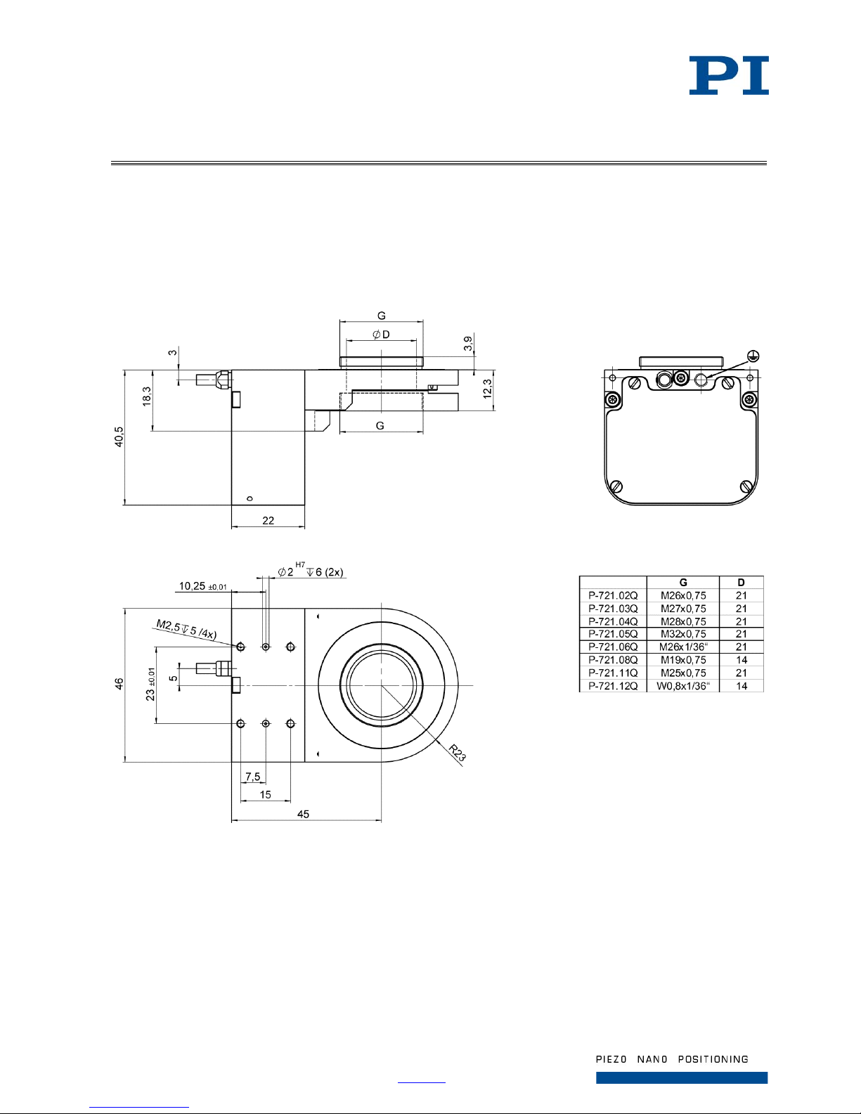
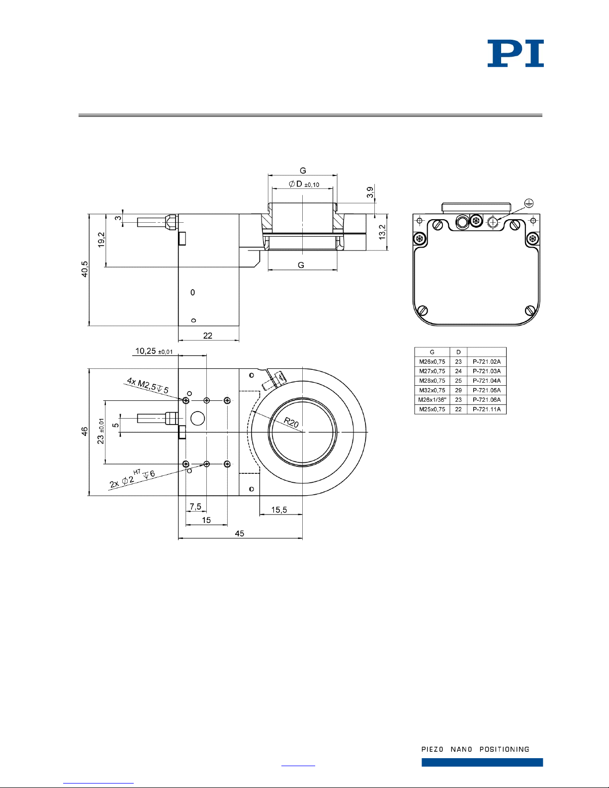
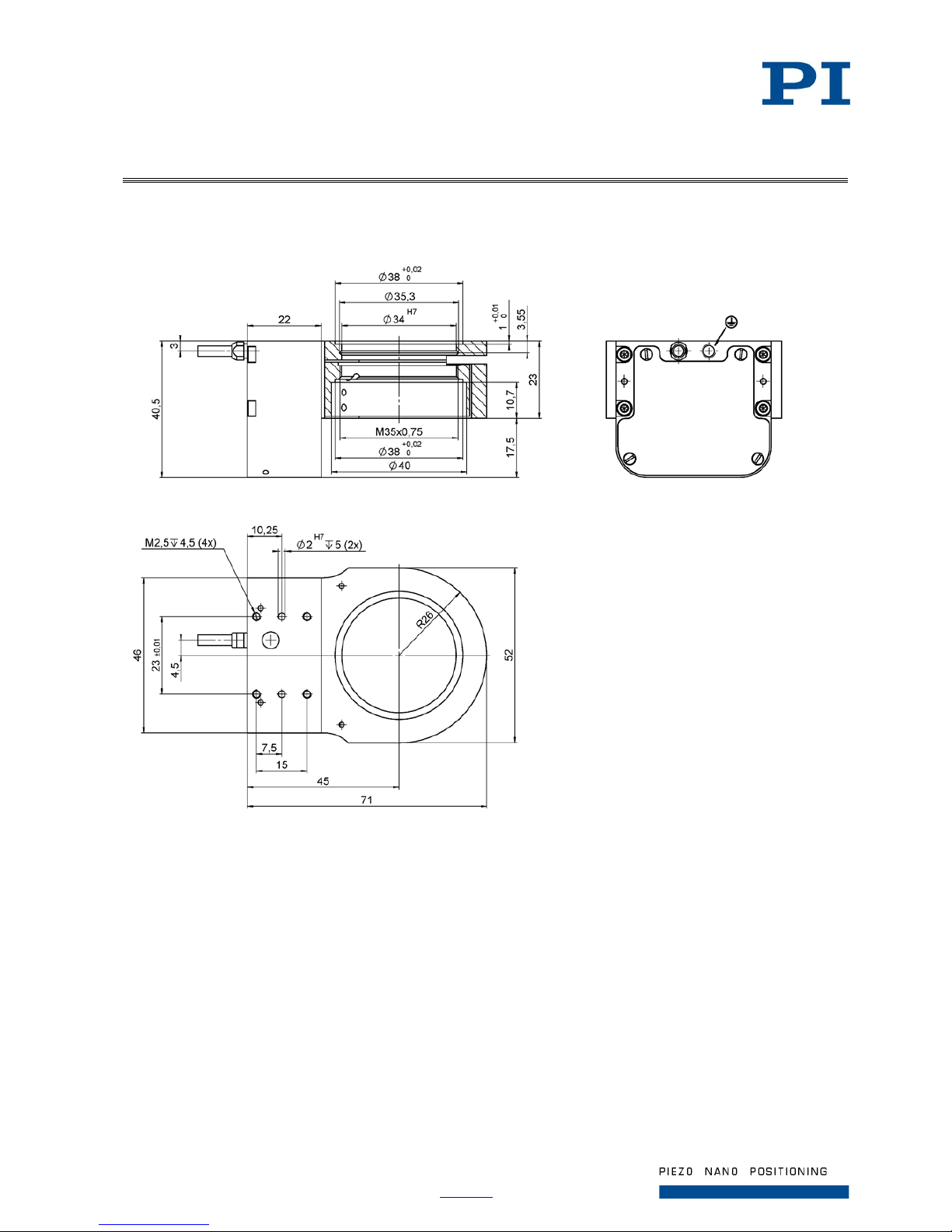
Dimensions
Dimensions in mm. Note that the decimal places are separated by a comma in the drawings.
P-725.xCD, P-725.xCL, P-725.x0L
Figure 6: P-725.xCD, P-725.xCL, P-725.x0L (P-721.xxQ adapter to be ordered separately)
Page 20
Page 20 / 25
2018-11-13
P725T0010, valid for P-725
Physik Instrumente (PI ) GmbH & Co. KG, Auf der Roemerstr. 1, 76228 Karlsruhe/Germany
Phone +49 721 4846-0, Fax +49 721 4846-1019, Email [email protected], www.pi.ws
P-725.xCA
Figure 7: P-725.xCA (P-721.xxA adapter to be ordered se par ately)
Page 21
Page 21 / 25
2018-11-13
P725T0010, valid for P-725
Physik Instrumente (PI ) GmbH & Co. KG, Auf der Roemerstr. 1, 76228 Karlsruhe/Germany
Phone +49 721 4846-0, Fax +49 721 4846-1019, Email [email protected], www.pi.ws
P-725.xDD
Figure 8: P-725.xDD
Page 22
Page 22 / 25
2018-11-13
P725T0010, valid for P-725
Physik Instrumente (PI ) GmbH & Co. KG, Auf der Roemerstr. 1, 76228 Karlsruhe/Germany
Phone +49 721 4846-0, Fax +49 721 4846-1019, Email [email protected], www.pi.ws
Pin Assignments
P-725.xCL, P-725.x0L
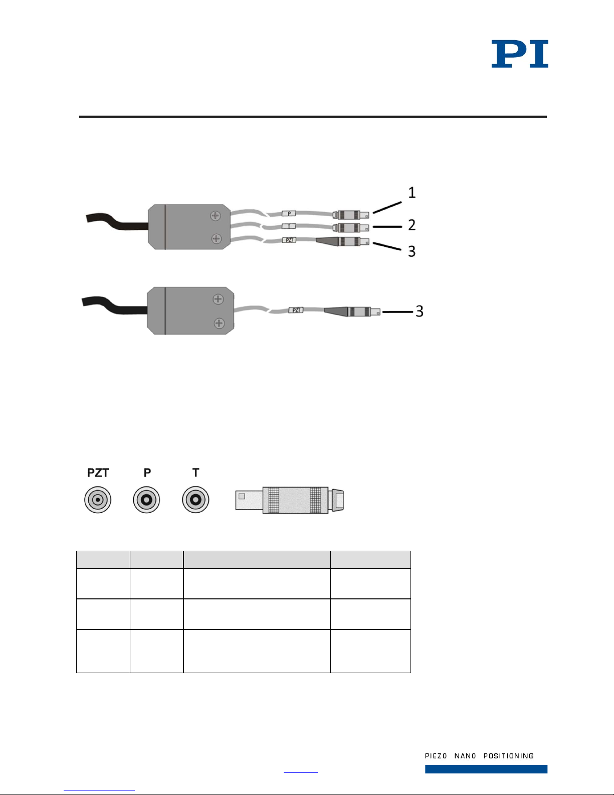
Figure 9: LEMO connectors of P-725.xCL (top) and P-725.x0L (bottom)
1 LEMO coaxial connector for capacitive sensor (Probe)
2 LEMO coaxial connector for capacitive sensor (Target)
3 LEMO coaxial connector for pi ezo voltage
LEMO coaxial connectors
Figure 10: LEMO coaxial connectors
Connector Signal Function Connector shell
P Probe Probe sensor signal (moving part
of the capacitive sensor)
Cable shield
T Target Target sensor signal (non-moving
part of the capacitive sensor)
Cable shield
PZT PZT Piezo voltage Ground of piezo
voltage on cable
shield
Page 23
Page 23 / 25
2018-11-13
P725T0010, valid for P-725
Physik Instrumente (PI ) GmbH & Co. KG, Auf der Roemerstr. 1, 76228 Karlsruhe/Germany
Phone +49 721 4846-0, Fax +49 721 4846-1019, Email [email protected], www.pi.ws
P-725.SDD
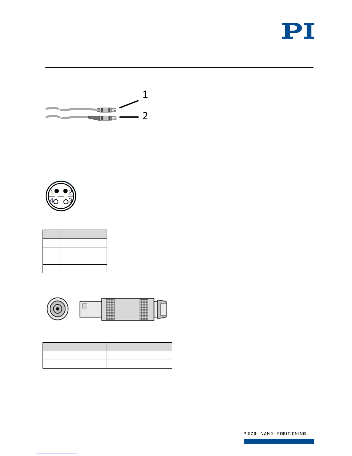
Figure 11: LEMO connectors of P-725.SDD
1 4-pin LEMO connector for strain gauge sensor
2 LEMO coaxial connector for piezo voltage
Sensor connector
Figure 12: Sensor connector, front view
Pin Function
1 Reference (5 V)
2 Sensor 3 Sensor +
4 GND
PZT connector
Figure 13: PZT connector, front view (left)
Pin Function
Inner contact PZT + (-20 to 120 V)
Connector shell PZT - (GND)
Page 24
Page 24 / 25
2018-11-13
P725T0010, valid for P-725
Physik Instrumente (PI ) GmbH & Co. KG, Auf der Roemerstr. 1, 76228 Karlsruhe/Germany
Phone +49 721 4846-0, Fax +49 721 4846-1019, Email [email protected], www.pi.ws
P-725.xCD, P-725.xCA, P-725.CDD
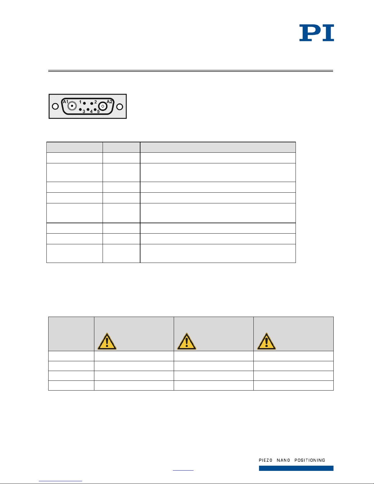
Figure 14: Sub-D 7W2 (m) connector, front view
Pin Signal Function
A1 inner conductor Input Piezo voltage +
A2 inner conductor Output Probe sensor signal
(nonmoving part of the capacitive sensor)
A2 outer conductor GND Shield
1 Bidirectional Data line for ID chip
2 GND Shield of Target
Ground of ID chip when switched on
3 Input Piezo voltage –
4 N.C. Not connected
5 Input Target sensor signal
(movable part of the capacitive sensor)
The connector shell is connected to the cable shield.
Maximum Ratings
The P-725 is designed for the following maximum ratings:
Model Maximum operating
voltage
Maximum operating
frequency (unloaded)
Maximum power
consumption
P-725.1xx -20 to 120 V 150 Hz 13 W
P-725.2xx -20 to 120 V 100 Hz 17.4 W
P-725.4xx -20 to 120 V 75 Hz 17.4 W
P-725.xDD -20 to 120 V 300 Hz 4.7 W
Page 25
Page 25 / 25
2018-11-13
P725T0010, valid for P-725
Physik Instrumente (PI ) GmbH & Co. KG, Auf der Roemerstr. 1, 76228 Karlsruhe/Germany
Phone +49 721 4846-0, Fax +49 721 4846-1019, Email [email protected], www.pi.ws
Ambient Conditions and Clas si fi ca ti ons
The following ambient conditions and classifications must be observed for the P-725:
Area of application For indoor use only
Maximum altitude 2000 m
Air pressure 1100 hPa to 1013 hPa
Relative humidity Highest relative humidity 80 % for temperatures up to 31 °C
Decreasing linearly to 50 % relative humidity at 40 °C
Storage temperature -20 °C to 80 °C
Transport temperature -25 °C to 85 °C
Overvoltage category II
Protection class I
Degree of pollution 1
Degree of protection
according to IEC 60529
IP20
Old Equipment Disposal
In accordance with EU law, electrical and electronic equipment may not be disposed of in EU member
states via the municipal residual waste.
Dispose of your old equipment according to international, national, and local rules and regulations.
In order to fulfil its responsibility as the product manufacturer, Physik Instrumente (PI) GmbH & Co.
KG undertakes environmentally correct disposal of all old PI equipment made available on the market
after 13 August 2005 without charge.
Any old PI equipment can be sent free of charge to the following address:
Physik Instrumente (PI) GmbH & Co. KG
Auf der Roemerstr. 1
D-76228 Karlsruhe, Germany
 Loading...