

Page 1
Operating instructions
Ripple tank with LED light source
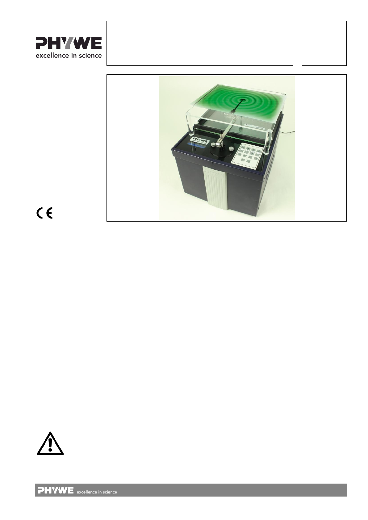
Ripple tank with LED light source, complete
11260-02
11260-88
PHYWE Systeme GmbH & Co. KG
Robert-Bosch-Breite 10
37079 Göttingen
Germany
The unit complies with
the corresponding
EC guidelines
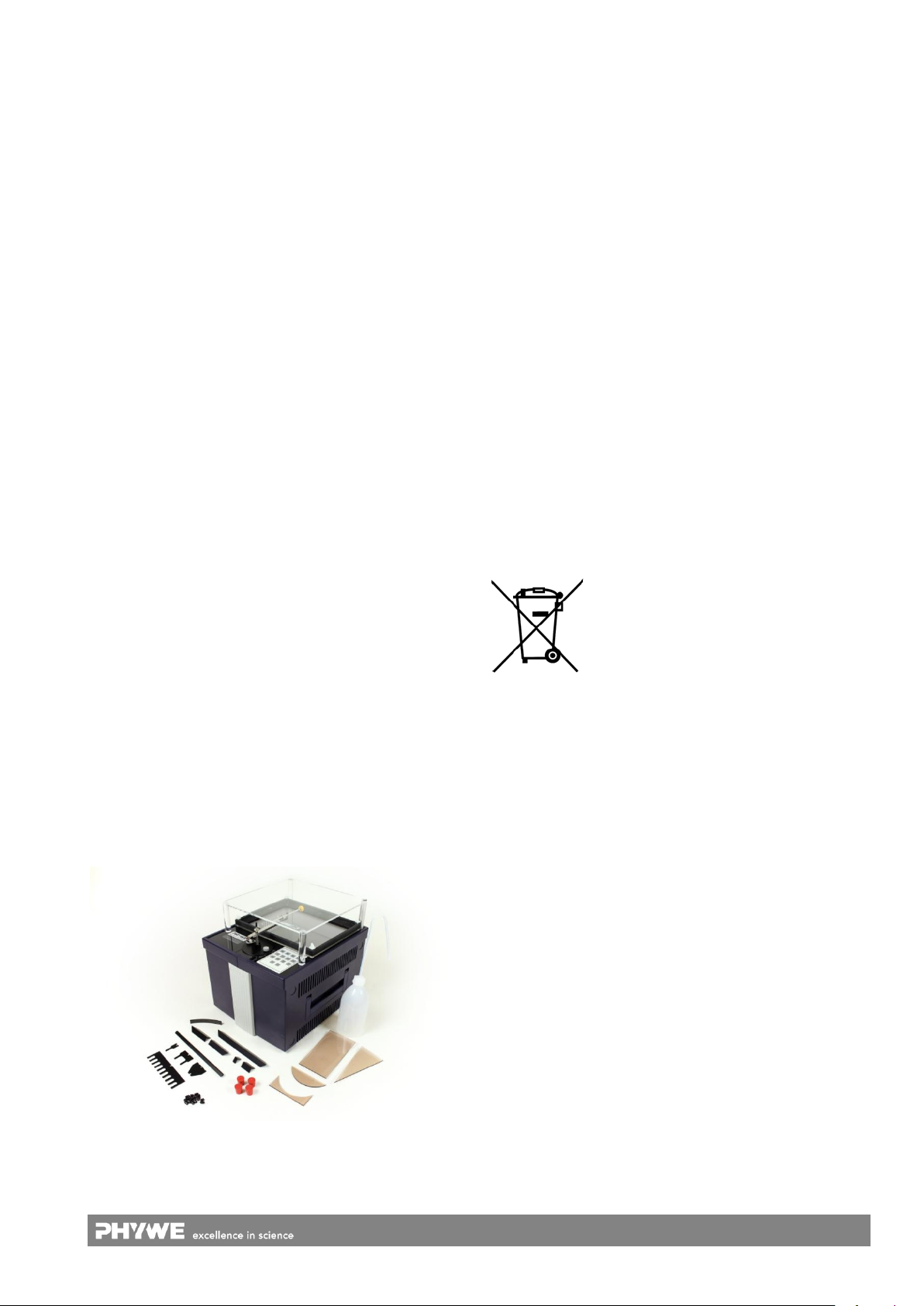
Fig. 1: Ripple tank with LED light source, complete 11260-88
Attention!
TABLE OF CONTENTS
1 SAFETY PRECAUTIONS
2 PURPOSE AND DESCRIPTION
3 FUNCTIONAL AND OPERATING ELEMENTS
4 HANDLING
5 NOTES ON OPERATION
6 TECHNICAL DATA
7 SCOPE OF SUPPLY
8 ACCESSORIES
9 LITERATURE
10 WARRANTY
11 WASTE DISPOSAL
1 SAFETY PRECAUTIONS
Carefully read these operating instructions completely
before operating this instrument. This is necessary to
avoid damage to it, as well as for user-safety.
1
www.phywe.com, © All rights reserved 11260-02 / -88 / 2516
Only use the instrument for the purpose for which it was
designed.
Only use the instrument in dry rooms in which there is no
risk of explosion.
Before applying mains voltage, ensure that the earth
lead of the experimental set-up is properly connected to
the mains earth lead. The mains plug is only to be
plugged into a mains socket which has an earth lead. Do
not use an extension cable without earth lead, as this
would negate the protective effect.
Check that your mains supply voltage corresponds to
that given on the type plate fixed to the supplied power
supply.
Assemble the experimental set-up in such a way that the
mains switch and/or plug connector of the instrument are
freely accessible. Keep the ventilation slots of the experimental set-up free of any covering.
Do not attempt to open the instrument.
Take care that no liquids or objects enter in through the
ventilation slots.
Do not connect any other devices to the ripple tank.
Caution: Separate the instrument completely from the
electric mains before loosening, exchanging or removing
any cable connection!
Separate the instrument completely from the mains be-
fore filling or emptying the wave tray!
Longer observation of the wave image under strobo-
scopic illumination can trigger epileptic seizures in endangered people.
Do not stare directly into the glowing LED on purpose.
Page 2
2 PURPOSE AND DESCRIPTION
Screen
Wave tray
LED
The ripple tank serves for the generation and study of surface
waves in water. It enables not only experiments that are
characteristic for surface waves in water to be carried out, but
also experiments that are analogous to those carried out on
light waves. Many important wave optics laws can be clearly
and simply demonstrated by means of water waves. The following describes how the ripple tank functions and how water
wave portrayal is accomplished.
Water waves are generated by a mechanical vibration generator that is integrated in the ripple tank (loudspeaker principle). This generator can cause either a single plug or several
plugs to be dipped into the water in the wave tray for the
generation of circular waves, or a slide to be dipped in for the
generation of flat waves with a frequency of between 5 Hz
and 60 Hz. Periodic dipping causes surface waves to be created.
A green LED is fixed to the bottom of the ripple tank housing.
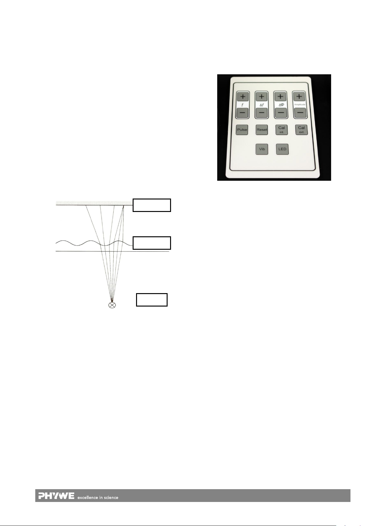
This illuminates the wave tray from below and, due to the optical principle of shadow projection (Fig. 2), produces a representation of the water waves that is rich in contrast. Either
continuous light or stroboscopic light can be used. Stroboscopic light allows the propagation velocity of the water
waves to be slowed down to a complete standstill. Details on
the use of stroboscopic light are given in section 4
“Handling”.
3 FUNCTIONAL AND OPERATING ELEMENTS
3.1 Control panel
The ripple tank apparatus is equipped with a control panel
with 14 keys (Fig. 3) and an LCD screen. In the following, an
introduction is given to the adjustment possibilities and the
wave generator required for the generation of water waves.
Fig. 3: The 14 keys control panel is situated on the top of the hous-
ing of the ripple tank.
1 Vib
Switches the vibration generator(s) on and off.
Fig. 2: The shadow projection principle – Light from a point light
source passes through the wave tray and is partially subject
to deflection according to the structure of the surface waves.
This deflection generates a bright-dark pattern on a screen.
When the drawing table that is supplied by default is placed
on the ripple tank, and a sheet of white paper is placed on
the table, then the water waves can be observed on the
sheet of paper.
No focussing optical elements are used in the portrayal of the
waves. The creation of the portrayal results exclusively from
the diffraction properties of the water surface.
Wave troughs make the light from the LED divergent, water
crests make it convergent. Because of this, the wave troughs
can be recognised as dark stripes on the observation surface
(sheet of paper) and the wave crests as bright stripes. The
result of this principle is a wave image that is sharp and rich
in contrast. It must be noted here though, that a good image
contrast is only given at small wave amplitudes. At larger
amplitudes, the light rays emitted by the LED combine far before they reach the observation screen and diverge from
each other again on the further long way to it. The result is
the disappearance of the wave image. For this reason, the
wave generator is equipped with an amplitude control element which ensures that the optimal generator amplitude can
be set for each individual experiment.
2 LED
Switches back and forth between the following settings
of the LED:
Continuous light
Stroboscopic light
Off
3 f
Pressing (+) increases, and pressing (−) reduces the
frequency within the 5 Hz and 60 Hz range.
4 Δf
A difference in frequency between the vibration generator and the stroboscopic light can be set here. The two
frequencies are equal in the default state, in which the
waves are depicted as a stationary wave under stroboscopic light. A frequency difference can be set with the
(+) and (−) keys to obtain a “slow motion” portrayal of the
waves.
5 Δφ
A phase difference between the integrated vibration
generator and an additional, external vibration generator
(11260-10) can be set here. In the default state, the
generator oscillates in phase. A phase difference of between 0° and 360° can be set in steps of 15°.
6 Amplitude
Pressing (+) increases the amplitude of the vibration
generator (4 steps), pressing (−) reduces it.
7 Pulse
Pressing this key gives the vibration generator a single
pulse which causes the plug to be dipped into the water
just once. On releasing the key, the plug is brought back
to the rest position. If the external vibration generator
(19) should be connected, it will also be operated.
2
www.phywe.com, © All rights reserved 11260-02 / -88 / 2516
Page 3
8 Reset
19
11
12
17
15
16
14
13
18
Switches the vibration generator and the LED off. All
other settings stay at their current value to allow a quick
restart of the ripple tank.
9 Cal int.
For calibration of the integrated vibration generator. The
amplitude of the exciter can be set in a range from 80 %
to 120 % – independent of the external vibration generator. If the amplitudes should vary, this enables a synchronisation of the amplitudes of the integrated and the
external vibration generator.
First press the Cal int. key. Immediately after that use
the (+) and (−) keys of the Amplitude selector (6) for fine-
tuning. The calibration is kept even after a reset (8) or after unplugging the power supply (11).
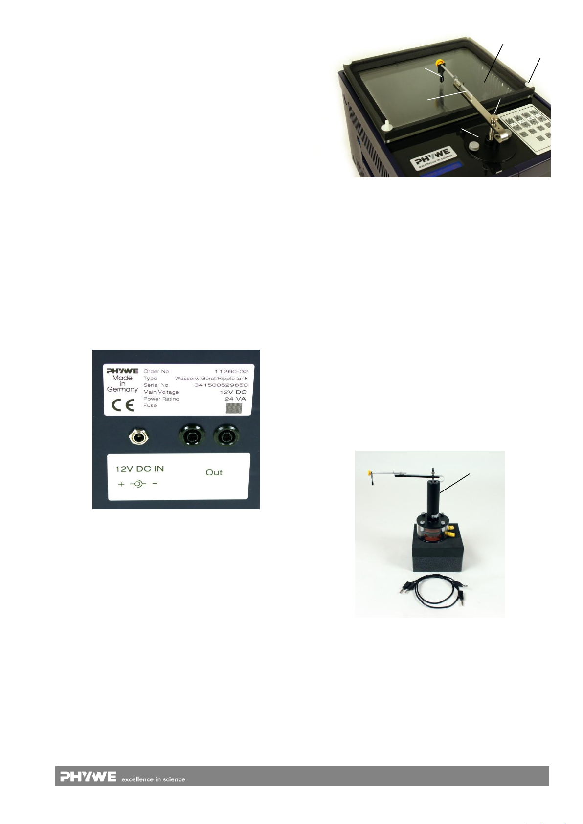
Fig. 5: Integrated vibration generator (15) with wave tray (13), hold-
ing rod (16), and plug (17).
10 Cal ext.
Same as (9) for calibration of the external vibration generator. The amplitude of the external exciter can be set
independently of that of the internal exciter in a range
from 80 % to 120 %.
First press the Cal ext. key. Immediately after that sue
the (+) and (−) keys of the Amplitude selector (6) for fine-
tuning.
3.2 Further functional elements
In addition to the control panel, the ripple tank has the following further functional elements (see Fig. 4, 5 and 6):
14 Adjusting screws, 4 pieces
For horizontal alignment of the wave tray.
15 Integrated vibration generator
Serves to hold each type of exciter. By loosening the two
adjusting screws in the base, the exciter can be rotated
in plane.
16 Holding rod
Serves to mount and position the respective wave generator.
17 Wave generator
Serves to generate waves by dipping into the water while
the integrated vibration generator is switched on.
18 Tensioning screw
For raising and lowering the wave generator to a suitable
position in the water of the wave tray.
19 External vibration generator (accessory: 11260-10)
Can be used as second generator and is necessary for
the “Doppler effect” experiment.
Fig. 4: Socket for the power supply (11) and sockets for the connec-
tion of the external vibration generator (12).
11 Connecting socket 12 V
For connection of the ripple tank apparatus to an external power supply (supplied by default). The socket is on
the side of the housing.
12 Connecting sockets, external vibration generator
An external vibration generator with 4 mm plugs can be
connected here. The polarity of the connection is of importance. To check polarity, the function Pulse (7) can
be used. If both the internal and external vibration gen-
Fig. 6: External vibration generator (11260-10) with accessories,
separately available.
erators move down when the button Pulse is pressed,
both will move in phase. Otherwise the polarity of the external vibration generator can be changed or the two vibrators work with a phase difference of 180°.
4 HANDLING
This section describes how to put the water wave apparatus
into operation and cause water waves to be generated.
13 Wave tray
Waves are generated in the water filled in the wave tray.
Plastic foam has been stuck to the inner sides of the
wave tray. This allows an almost complete absorption of
the water waves that hit the sides of the wave tray and
thereby avoids unwanted wave reflections.
Please read this section carefully to avoid failure or improper
operation.
Note: To protect the apparatus from damage, the vibration
generator turns off automatically after 10 minutes of
continuous operation. Experiments are not expected to
take longer time in this operation mode.
3
www.phywe.com, © All rights reserved 11260-02 / -88 / 2516
Page 4
4.1 Putting the ripple tank into operation
Attention!
First connect the connecting socket (11) of the ripple tank via
the provided power supply to the mains. The LCD screen
lights up and the ripple tank is ready to use.
4.2 Filling the wave tray
First, the empty wave tray has to be placed on the ripple
tank. Afterwards, it can be carefully filled with water. The
wash-bottle supplied can be used to fill the wave tray. Fill the
tray about three quarters high. After this, to have reflection of
water waves at the sides suppressed, moisture the whole
side-foam with a finger so that water can wet it.
Use the adjusting screws (14) to align the wave tray horizontally. To do so, we recommend that you look flat across the
water surface and use the height of the water level at the different sides of the tray as reference. Now use the screws to
bring the tray to about the same height on all sides and so to
a horizontal position.
Fix the holding rod with slide to the exciter and bring it to the
lower end of the wave tray. The wave tray must now be correctly adjusted, as the slide must be exactly evenly immersed
into the water. If this is not done precisely, the wave image
will be distorted and unclear. See the information given on
the correct adjustment of the wave tray in section 4.2 “Filling
the wave tray”.
The slide must also be set to be horizontal. Therefore, fix it
as horizontally as possible to the integrated exciter and
tighten the clamping screw on the exciter further until the
slide is held slightly above the water surface. Use the water
surface as reference to adjust the slide to the horizontal position. Afterwards, turn the clamping screw on the exciter further until the slide is dipped into the water (about 1 to 2 mm).
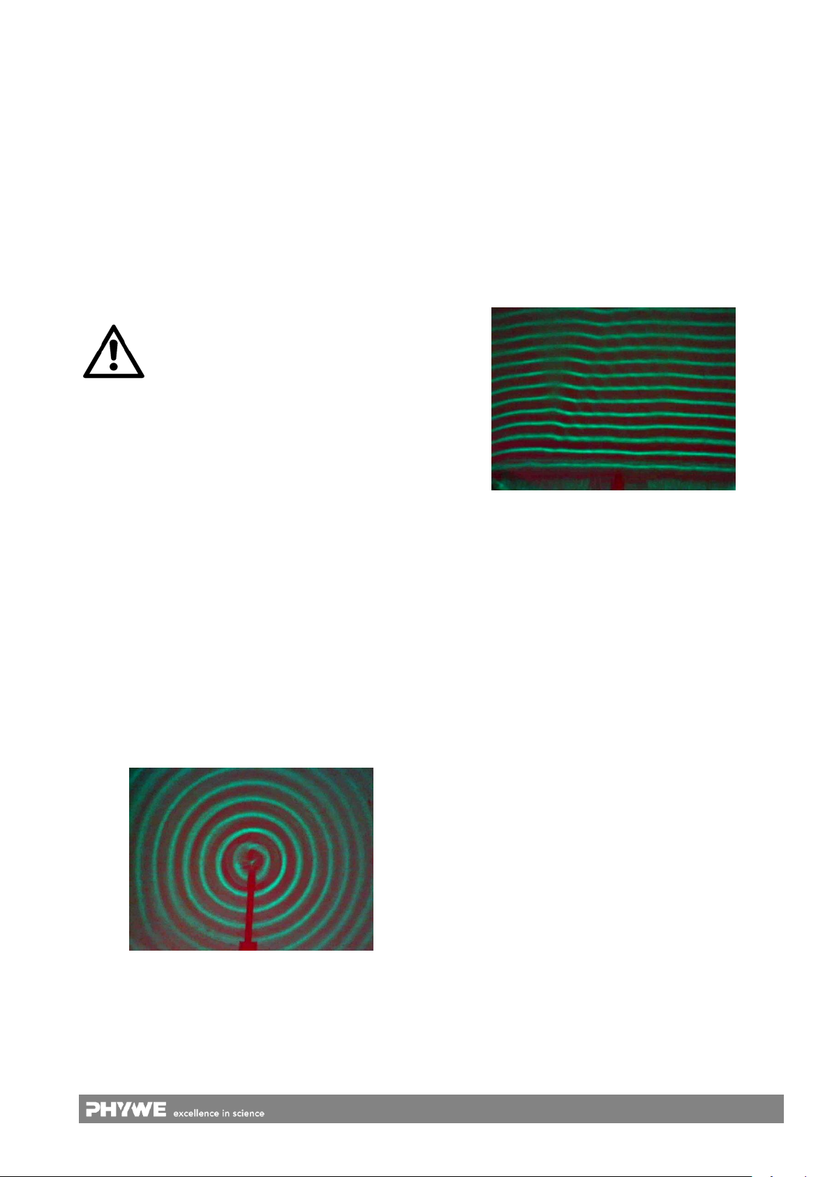
Set a frequency between 18 Hz and 25 Hz and choose a
small amplitude as well as continuous light. A wave image
should be obtained that is similar to that shown in Fig. 8.
When lifting the filled tray, the water tends to slop! Pay
attention that no water enters the device.
We recommend using the wash-bottle or e.g. a sponge to
finally remove the water while the wave tray is still resting on
the ripple tank.
4.3 Cleaning
The cover plate and the wave tray of the ripple tank consist of
acrylic glass. Please perform cleaning of the cover plate and
the wave tray with suitable (i.e., non-abrasive) tissues without
aggressive chemicals added.
4.4 Generation of circular waves
Fix the holding rod (16) with a single plug (17) to the integrated generator (15) and bring it to the middle of the wave
tray. Turn the clamping screw on the generator until the plug
is dipped into the water in the wave tray. Set to continuous
light, to a frequency of between 5 Hz and about 20 Hz and to
a small amplitude (1 or 2). Prepare the observation surface
by placing a sheet of white paper on the drawing table situated over the wave tray. Darkening the room could be useful
for better visibility of the wave image.
Should the wave image be distorted or unclear, vary the frequency f and/or the amplitude until a wave image is obtained
that is similar to that shown in Fig. 7.
Fig. 8: Flat waves generated by the plane exciter.
Should the wave image be distorted or unclear, vary the frequency, the amplitude or the immersion depth. When no improvement in the wave image results, it could be possible
that the slide is not correctly adjusted and therefore does not
dip evenly into the water. In this case, align the slide as described above.
4.6 Usage of the stroboscopic light
The use of stroboscopic light is only instructed in those individual experiments in which it is required to reach the experimental target. All other experiments should first be carried out without stroboscopic light because stroboscopic illumination considerably changes the impression of the image,
partially. Interference patterns can be far more impressively
seen when continually projected than when under stroboscopic illumination.
In this context it must be considered that for continuous light,
the human eye is only capable of recognizing the wave image in the lower frequency range. Because of this, we recommend that only frequencies of up to about 30 Hz be used
under continuous light. Stroboscopic light should be used
with shorter wavelengths (higher frequencies), so that wave
propagation is slowed down and made visible to the human
eye.
5 NOTES ON OPERATION
This high-quality instrument fulfils all of the technical re-
Fig. 7: Circular waves generated by the plug-shaped exciter.
quirements that are compiled in current EC guidelines. The
characteristics of this product qualify it for the CE mark.
This instrument is only to be put into operation under special-
4.5 Generation of flat waves
The generation of flat waves is somewhat more difficult, because it requires an exact alignment of the wave tray with the
slide used. It could be necessary to add 1 to 2 drops of a
soap solution to the water for better wetting. Do not exceed
this amount, however, as then turbidity and foaming would
ist supervision in a controlled electromagnetic environment in
research, educational and training facilities (schools, universities, institutes and laboratories). This means that in such an
environment, no mobile phones etc. are to be used in the
immediate vicinity. The individual connecting leads are each
not to be longer than 2 m.
occur and cause deterioration in the quality of the image.
4
www.phywe.com, © All rights reserved 11260-02 / -88 / 2516
Page 5
The instrument can be so influenced by electrostatic charges
Should you no longer require this product,
do not dispose of it with the household refuse.
Please return it to the address below for
proper waste disposal.
and other electromagnetic phenomena that it no longer functions within the given technical specifications.
The following measures reduce or eliminate the effect of such
disturbances: Avoid fitted carpets; ensure potential equalization; carry out experiments on a conductive, earthed surface,
use screened cables, do not operate high-frequency emitters
(radios, mobile phones) in the immediate vicinity.
This instrument complies with Class A, Group 1 of the
EN 55011 norm and it is only permitted to operate unlimitedly
outside of residential areas. Should electromagnetic disturbances, despite the limitations of usage to a technical room
of a school or other place of education, occur in a surrounding residential area, then it can be demanded of the operator
that he or she carries out appropriate measures (e.g. screening, longer distance away from sensitive equipment, shorter
operating principles, as short as possible connecting cables
etc.) at his or her own cost.
6 TECHNICAL DATA
(typical for 25 °C)
Operating temperature range 5...40 °C
Relative humidity < 80 %
Frequency 5…60 Hz
Vibration generator amplitude 1…4
Stroboscope frequency (Δf) −2.5…2.5 Hz
Phase difference 0…360°
Line voltage 110…240 V
Mains frequency 50/60 Hz
8 ACCESSORIES
Various experiments, such as the “Doppler effect” experiment, or demonstration of experiments via a mirror, require
accessories. The following are available:
External vibration generator for ripple tank 11260-10
Demonstration set with mirror for ripple tank 11260-30
9 LITERATURE
Demonstration Experiments: Experiments with
the ripple tank 16040-02
10 WARRANTY
We guarantee the instrument supplied by us for a period of
24 months within the EU, or for 12 months outside of the EU.
Excepted from the guarantee are damages that result from
disregarding the Operating Instructions, from improper handling of the instrument or from natural wear.
The manufacturer can only be held responsible for the function and technical safety characteristics of the instrument,
when maintenance, repairs and alterations to the instrument
are only carried out by the manufacturer or by personnel who
have been explicitly authorized by him to do so.
11 WASTE DISPOSAL
The packaging consists predominately of environmentally
compatible materials that can be passed on for disposal by
the local recycling service.
LED luminous flux, max. 285 lm
Dimensions (mm) 300 x 370 x 330 (W x L x H)
Tray area (mm) 280 x 210 (W x L)
Weight approx. 5.7 kg
7 SCOPE OF SUPPLY
The “Ripple tank with LED light source, complete” (11260-88)
is supplied with the following components:
Basic unit 11260-02
Power supply 12 V DC / 2 A 12151-99
Accessory set for ripple tank 11260-12
Drawing table for ripple tank 11260-13
Wave tray for ripple tank 11260-14
PHYWE Systeme GmbH & Co. KG
Customer Service
Robert-Bosch-Breite 10
D–37079 Göttingen
Germany
Phone +49 (0) 551 604-274
Fax +49 (0) 551 604-246
Fig. 9: Scope of supply of ripple tank with LED, complete 11260-88.
5
www.phywe.com, © All rights reserved 11260-02 / -88 / 2516
 Loading...