

Page 1

phytron
9/2013 Manual MA 2120-A002 EN
APS-Arduino Shield
Evaluation Board for the
APS Stepper Motor Power Stage
TRANSLATION OF THE GERMAN ORIGINAL MANUAL
Page 2

Manual APS-Arduino Shield
MA 2120-A002 EN
2
© 2013
All rights with:
Phytron GmbH
Industriestraße 12
82194 Gröbenzell, Deutschland
Tel.: +49(0)8142/503-0
Fax: +49(0)8142/503-190
In this manual you will find the descriptions of the features and specifications of the
evaluation board: APS-Arduino Shield
This manual is also a supplementary to the “APS Module High Performance Stepper Motor
Power Stage“ manual.
Every possible care has been taken to ensure the accuracy of this technical manual. All
information contained in this manual is correct to the best of our knowledge and belief but
cannot be guaranteed. Furthermore we reserve the right to make improvements and
enhancements to the manual and / or the devices described herein without prior
notification.
We appreciate suggestions and criticisms for further improvement.
Email address: doku@phytron.de
Questions about the use of the product described in the manual that you cannot find
answered here, please contact your representative of phytron (http://www.phytron.eu/) in
your local agencies.
Page 3

phytron
3 MA 2120-A002 EN
1 Information
i
This manual:
Read this manual very carefully before mounting, installing and operating the
device and if necessary further manuals related to this product.
- Please pay special attention to instructions that are marked as follows:
DANGER –
Serious injury!
Indicates a high risk of serious injury or
death!
DANGER –
Serious injury from
electric shock!
Indicates a high risk of serious injury or
death from electric shock!
WARNING –
Serious injury
possible!
Indicates a possible risk of serious injury
or death!
WARNING –
Serious injury from
electric shock!
Indicates a possible risk of serious injury
or death from electric shock!
CAUTION –
Possible injury!
Indicates a possible risk of personal
injury.
i
CAUTION –
Possible damage!
Indicates a possible risk of damage to
equipment.
CAUTION –
Possible damage
due to ESD!
Refers to a possible risk of equipment
damage from electrostatic discharge.
i
“Any heading”
Refers to an important paragraph in the
manual.
Page 4

Manual APS-Arduino Shield
MA 2120-A002 EN 4
Observe the following safety instructions!
Qualified personnel
WARNING – Serious injury possible!
Serious personal injury or serious damage to the machine and drives could
be caused by insufficiently trained personnel!
Without proper training and qualifications damage to devices and injury
might result!
- Design, installation and operation of systems may only be performed
by qualified and trained personnel.
- These persons should be able to recognize and handle risks
emerging from electrical, mechanical or electronic system parts.
- The qualified personnel must know the content of this manual and be
able to understand all documents belonging to the product. Safety
instructions are to be provided.
- The trained personnel must know all valid standards, regulations and
rules for the prevention of accidents, which are necessary for
working with the product.
Safety Instructions
Further manual
This manual is a supporting manual for the following manual:
“APS Module High Performance Stepper Motor Power Stage“
- First read the basic manual and then the EVA-APS manual.
i
Intended use:
The APS module is designed for operating in a drive system.
- An installation is allowed only if the requirements of the EC Machinery
and EMC Directives are conformed with.
i
Part of a machine:
This product is used as a part of a complete system, therefore risk
evaluations concerning the specific application must be made before using
the product.
- Safety measures have to be taken according to the results and be
verified.
- Personnel safety must be ensured by the concept of this overall system
(e.g. machine concept).
Page 5

phytron
5 MA 2120-A002 EN
WARNING – Serious injury from electric shock!
If the APS module is not operated with SELV/PELV voltages, the risk of
dangerous voltages may be on the device. Touching these components
carrying high voltages can cause serious injury or death from electric shock:
- Always observe the safety concept SELV / PELV to ensure safe
insulation and separation of low voltage supplies from the mains.
WARNING – Serious injury from electric shock!
During electrical installation cables, connectors, etc. can be live.
- Before starting wiring, make sure that none of the power supplies are
connected to the primary side of the mains supply. Isolate the power
supplies from the mains or remove the appropriate fuses.
- The APS module must be plugged into the EVA-APS board before
installation.
- Do not plug or unplug the modules while powered.
- Do not plug or unplug the connectors while powered.
- If the equipment was energised, wait 3 minutes after power off to allow
the capacitors to discharge and ensure that there are no residual
charges on cables, connectors and boards
Page 6

Manual APS-Arduino Shield
MA 2120-A002 EN 6
2 Contents
1 Information ................................................................................................................. 3
2 Contents ..................................................................................................................... 6
3 Overview .................................................................................................................... 7
4 Block Scheme ............................................................................................................ 9
5 Technical Data .......................................................................................................... 10
5.1 Mechanical Data ................................................................................................... 10
5.2 Transport and Storage ......................................................................................... 10
5.3 Features ............................................................................................................... 11
6 Installation ................................................................................................................ 12
6.1 Mechanical Installation ......................................................................................... 12
6.2 Electrical Installation ............................................................................................. 14
6.2.1 Connectors - Overview .................................................................................. 14
6.2.2 Connector Assignment .................................................................................. 15
6.2.3 APS Power Stage Module ............................................................................. 16
6.2.4 Connection – Power Supply and Motor ......................................................... 17
7 Commissioning ........................................................................................................ 20
8 Service ....................................................................................................................... 21
9 Warranty, Disclaimer and Registered Trademarks ............................................... 22
9.1 Disclaimer ............................................................................................................. 22
9.2 Warranty ............................................................................................................... 22
9.3 Registered Trademarks ........................................................................................ 22
10 Circuit diagram ......................................................................................................... 23
11 Index .......................................................................................................................... 24
Page 7

phytron
7 MA 2120-A002 EN
3 Overview
APS-Arduino Shield is an evaluation board for the application of the high performance
APS stepper motor power stage (5 A
PEAK
at 24 - 70 VDC) in research, prototyping, model
making and art installations.
Fig.1 APS-Arduino shield module with APS power stage (left) and Arduino board (right)
• APS power stage parameters and diagnostics via Serial Peripheral Interface (SPI)
• Control pulses and direction signal comes from the digital pins of the Arduino
• Download a demo program and its description from the phytron website
Page 8

Manual APS-Arduino Shield
MA 2120-A002 EN 8
Connections
– Power supply
– Motor connection
– PCB connectors (APS):
2 mm grid; 0.5 mm pin (Fischer Elektronik company)
Pins: 2x10 and 2x12
– Reset button
Manuals available
• Manual APS-Arduino shield (this manual)
• Manual APS
WARNING – Damage by wrong motor current setting!
The power stage is set on delivery to a defined current value. Please check the
adjusted current for the stepper motor before installation (see the motor data).
Page 9

phytron
9 MA 2120-A002 EN
4 Block Scheme
Fig.2 Block scheme
i
Power supply voltage:
The APS supply (24 – 70 V) is not connected to the Arduino supply.
APS Arduino Shield requires its own power supply to supply the APS power
stage!
The Arduino is not supplied by the APS supply (24-70 V).There is no
electrical isolation of the supplies.
Please note the Arduino manual for the power supply of the Arduino board!
Page 10

Manual APS-Arduino Shield
MA 2120-A002 EN 10
5 Technical Data
5.1 Mechanical Data
Dimensions 53 x 84 mm
Weight with APS: 57 g
without APS: 41 g
Mounting pluggable on Arduino board
5.2 Transport and Storage
Permissible transport and storage conditions:
Transport and storage
temperature:
-40 to +70 °C
Relative humidity max. 95 % , no condensation and ice permissible
Package: Always in ESD packing
CAUTION – Possible damage by ESD!
The module consists of sensitive electronic components that can be destroyed
by electrostatic discharge voltages.
- Always store and transport single modules in ESD protective packaging.
- Always handle the components in compliance with the ESD protection
measures.
- No liability is accepted for any consequences resulting from improper
handling or non-ESD-friendly packaging.
i
CAUTION – Possible damage by collisions!
The APS module consists of sensitive electronic and mechanical components.
- Avoid collisions to the module.
Page 11

phytron
11 MA 2120-A002 EN
5.3 Features
Operation/Connection
Motor voltage supply 24 VDC to 70 VDC input range of supply of the power stage
Analogue outputs (motor) A, B, C, D for a 2 phase stepper motor connected as a
4-lead stepper motor
6- or 8-lead stepper motors should be connected as a
4-lead stepper motor.
SPI For parameterising and diagnostics of the power stage
Control pulses/direction
interface
Control pulses and direction signal from the digital pins
of the Arduino
PCB connectors (APS)
2 mm grid; 0.5 mm pin
Pins: 2x10 and 2x12
Pushbutton Reset of the Arduino
Page 12

Manual APS-Arduino Shield
MA 2120-A002 EN 12
6 Installation
6.1 Mechanical Installation
The APS is delivered as a single module board.
Unpack the module carefully in ESD protected area only.
Fig.1 Dimension in mm
CAUTION – Possible damage by ESD!
The module consists of sensitive electronic components that can be
destroyed by electrostatic discharge voltages.
- Always store and transport single modules in ESD protective
packaging.
- Always handle the components in compliance with the ESD protection
measures.
- No liability is accepted for any consequences resulting from improper
handling or non-ESD-friendly packaging.
Page 13

phytron
13 MA 2120-A002 EN
i
CAUTION – Possible damage!
The module is designed for a maximum supply voltage of 70 V
DC
. If it is
supplied with >70 V
DC
the card might be damaged.
- Make sure that a power supply is used with less than 70 V
DC
to avoid
damage.
Before integrating or changing the APS module always make sure that the APS-Arduino
shield is shut down and the power supply is disconnected.
WARNING – Serious injury from electric shock!
During electrical installation cables, connectors, etc. can be live.
- Before starting wiring, make sure that none of the power supplies are
connected to the primary side of the mains supply. Isolate the power
supplies from the mains or remove the appropriate fuses.
- Do not plug or unplug the modules while powered.
- Do not plug or unplug the connectors while powered.
- If the equipment was energised, wait 3 minutes after power off to
allow the capacitors to discharge and ensure that there are no
residual charges on cables, connectors and boards.
Now you can start with the electrical installation.
Page 14

Manual APS-Arduino Shield
MA 2120-A002 EN 14
6.2 Electrical Installation
Ensure sufficient bending radius of the cables during installation. Do not lay the cables in
tension or bend them.
If all the connections are made, the last step is to plug in the power supply to the mains.
6.2.1 Connectors - Overview
Connector Number of
pins
Connector on the module
Mating connector
PCB connector 2x12 2 mm grid
(e.g. SLY8 SMD062-24-S)
e.g. BLY8 SMD-…
PCB connector 2x10 2 mm grid
(e.g. SLY8 SMD062-20-S)
e.g. BLY8 SMD-…
Supply 1x2 PCB terminal block
Phoenix MKDS 1/2-3,81
–
Motor 2x2 PCB terminal block
Phoenix MKDS 1/2-3,81
–
Page 15

phytron
15 MA 2120-A002 EN
6.2.2 Connector Assignment
The following is the assignment of the PCB connectors:
Fig.2 Connection
Page 16

Manual APS-Arduino Shield
MA 2120-A002 EN 16
6.2.3 APS Power Stage Module
Fig.3 Pin assignment “BU1”
Fig.4 Pin assignment “BU2”
Page 17

phytron
17 MA 2120-A002 EN
6.2.4 Connection – Power Supply and Motor
Permissible supply voltage range: 24 to 70 VDC
Fig.5 Power supply and motor connection
Page 18

Manual APS-Arduino Shield
MA 2120-A002 EN 18
Wiring Schemes
Stepper motors with 0.1 to 5 A
PEAK
phase current can be controlled at a maximum of 70
V
DC
with the APS module Arduino shield.
Fig.6 Connection diagrams for 4,(6) and 8 lead stepper motors
Stepper motors with 8 leads can be connected with the windings wired in parallel (1) or
series (2).
Page 19

phytron
19 MA 2120-A002 EN
For 6 lead stepper motors, wiring scheme (3) with series windings is recommended.
If wiring scheme (3) cannot be used because of the motor construction, the motor may be
operated with only two of the four windings energized according to wiring scheme (5).
i
CAUTION – Possible damage!
Destruction of the power stage by connecting a 5 phase stepper motor.
- Do not connect any 5 phase stepper motors to avoid damage.
Motor time constant τ:
R
L
=
τ
applies to the electrical motor time constant τ.
The total inductance L
total
is equal to the winding inductance in a parallel circuit,
because of interlinked inductances.
L
total
= 4 x L applies to a series circuit.
The result is an equal motor time constant τ for a serial and a parallel circuit:
Circuit series parallel
Resistance R
total
2 x R
2
R
Inductance L
total
4 x L L
Motor time constant τ
R
L x 2
R x 2
L x 4
series ==τ
R
L x 2
R/2
L
parallel ==τ
Page 20

Manual APS-Arduino Shield
MA 2120-A002 EN 20
7 Commissioning
Please follow the described order when you put into service the evaluation board:
1. Plug the APS power stage onto the socket connectors of the APS-Arduino shield.
2. Plug the shield onto the Arduino board.
3. Screw the wire ends of the motor cable to the 4-pin socket.
4. Screw the wire ends of the supply cable to the 2-pin socket.
5. Connect the PC via USB cable.
6. Power on.
7. Parameterise the APS power stage via SPI Interface and Arduino software.
i
CAUTION – Possible damage!
Some modules are set to a default value on delivery. So e.g., the motor
current must be set to the corresponding value (see the motor data from
the motor manufacturer). Connected components like motors can be
damaged by incorrectly set values.
- Please check if the parameters are correct before starting.
Page 21

phytron
21 MA 2120-A002 EN
8 Service
In case of a service contract, please proceed as follows:
First try to identify the technical problem. Feel free to ask our support team for help. We
are pleased to assist you.
Removal of a module:
- Switch off the supply voltage
- Disconnect the supply voltage
- Carefully pull the APS module from the carrier board.
- To send a module to phytron use ESD packaging only.
Page 22

Manual APS-Arduino Shield
MA 2120-A002 EN 22
9 Warranty, Disclaimer and Registered Trademarks
9.1 Disclaimer
Phytron GmbH has verified the contents of the manual to match with the hardware and
software. However, errors and omissions are exempt and Phytron GmbH assumes no
responsibility for complete compliance. The information contained in this publication is
reviewed regularly and any necessary corrections are included in subsequent editions.
9.2 Warranty
The APS modules are subject to legal warranty. Phytron will repair or exchange devices
which show a failure due to defects in material or caused by the production process. This
warranty does not include damage caused by the customer, for example, not intended
use, unauthorised modifications, incorrect handling or wiring.
9.3 Registered Trademarks
In this manual several trademarks are used which are no longer explicitly marked as
trademarks within the text. The lack of these signs may not be used to draw the conclusion
that these products are free of rights of third parties. Some product names used herein are
for instance.
• ServiceBus-Comm
TM
is a trademark of the Phytron GmbH.
• Microsoft is a registered trade mark and WINDOWS is a trade mark of the Microsoft
Corporation in the USA and other countries.
Page 23
phytron
23 MA 2120-A002 EN
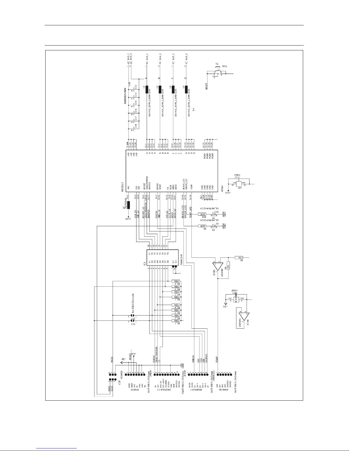
10 Circuit diagram
Fig.7 Circuit diagram of the APS-Arduino shield
Page 24

Manual APS-Arduino Shield
MA 2120-A002 EN 24
11 Index
C
Copyright 2
H
Handling 8
I
Inductance 19
Installation 14
M
Motor time constant 19
R
Rotary switch mode 20
S
Service 21
W
Warranty 22
Wiring scheme 19
 Loading...