


A product of a PHYTEC Technology Holding company
QuickStart Instructions
SPS-Kit
phyCORE-MPC5200B tiny
Using CoDeSys from 3S
Note: The PHYTEC SPS-Kit-Disc includes the electronic version of
the English phyCORE -MPC5200Tiny Hardware Manual
®
Edition: November 2006

SPS-Kit with phyCORE-MPC5200 QuickStart Instructions
© PHYTEC Meßtechnik GmbH 2006 L-688e_2
In this manual copyrighted products are not explicitly indicated. The absence of
the trademark (™) and copyright (©) symbols does not imply that a product is not
protected. Additionally, registered patents and trademarks are similarly not
expressly indicated in this manual.
The information in this document has been carefully checked and is believed to be
entirely reliable. However, PHYTEC Messtechnik GmbH assumes no
responsibility for any inaccuracies. PHYTEC Messtechnik GmbH neither gives
any guarantee nor accepts any liability whatsoever for consequential damages
resulting from the use of this manual or its associated product. PHYTEC
Messtechnik GmbH reserves the right to alter the information contained herein
without prior notification and accepts no responsibility for any damages which
might result.
Additionally, PHYTEC Messtechnik GmbH offers no guarantee nor accepts any
liability for damages arising from the improper usage or improper installation of
the hardware or software. PHYTEC Messtechnik GmbH further reserves the right
to alter the layout and/or design of the hardware without prior notification and
accepts no liability for doing so.
© Copyright 2006 PHYTEC Messtechnik GmbH, 55129 Mainz, Germany.
Rights - including those of translation, reprint, broadcast, photomechanical or
similar reproduction and storage or processing in computer systems, in whole or
in part - are reserved. No reproduction may be made without the explicit written
consent from PHYTEC Messtechnik GmbH.
EUROPE NORTH AMERICA
Address: PHYTEC Technologie Holding AG
Robert-Koch-Str. 39
55129 Mainz
GERMANY
PHYTEC America LLC
203 Parfitt Way SW, Suite G100
Bainbridge Island, WA 98110
USA
Ordering
Information:
+49 (800) 0749832
order@phytec.de
1 (800) 278-9913
sales@phytec.com
Technical
Support:
+49 (6131) 9221-31
support@phytec.de
1 (800) 278-9913
support@phytec.com
Fax: +49 (6131) 9221-33 1 (206) 780-9135
Web Site: http://www.phytec.de http://www.phytec.com
2nd Edition: November 2006

Introduction
1 Introduction .........................................................................................2
© PHYTEC Meßtechnik GmbH 2006 L-688e_2
1.1 Rapid Development Kit Documentation ......................................2
1.2 Professional Support Packages available .....................................2
1.3 Overview of this QuickStart Instruction.......................................3
1.4 Conventions used in this QuickStart ............................................4
1.5 System Requirements ...................................................................5
1.6 The PHYTEC phyCORE-MPC5200B tiny..................................6
1.7 Software Development Tool Chain..............................................8
1.7.1 CoDeSys..........................................................................8
2 Getting Started.....................................................................................9
2.1 Installing SPS Kit Software..........................................................9
2.1.1 Requirements of the Host Platform.................................9
2.1.2 SPS Kit Setup ..................................................................9
2.2 Downloading and starting the CoDeSys run-time system on the
Target..........................................................................................12
2.2.1 Setting the jumpers on the Development Board............15
2.2.2 Connecting the host to the target...................................16
2.2.3 Configuring the host......................................................17
2.2.4 Configuring the target....................................................18
2.3 Running the demo application....................................................20
3 Getting More Involved......................................................................24
3.1 Configuring the demo application..............................................24
3.2 Starting the demo application.....................................................28
4 Debugging...........................................................................................29
4.1 Starting the debugger..................................................................29
4.2 Setting a breakpoint....................................................................30
4.3 Visualization...............................................................................31
5 Further Information..........................................................................34
5.1 Running your application without the CoDeSys IDE................34
5.2 Starting the program when booting the target............................35
5.3 Writing I/O drivers .....................................................................37
6 Summary............................................................................................38
5 min
35 min
25 min
30 min
15 min

SPS-Kit with phyCORE® phyCORE-MPC5200 QuickStart Instructions
1 Introduction
5 min
This QuickStart provides general information on the PHYTEC
phyCORE-MPC5200B tiny Single Board Computer. It gives an
overview of CoDeSys software development tool chain and
instructions on how to run example programs on the
phyCORE-MPC5200B tiny in conjunction with the CoDeSys
development environment.
Please refer to the
phyCORE-MPC5200B tiny Hardware Manual
for specific information on such board-level features as
jumper
configuration
, memory mapping and pin layout. Selecting the
links on the electronic version of this document links to the
applicable section of the phyCORE-MPC5200B tiny Hardware
Manual.
1.1
1.2
Rapid Development Kit Documentation
This "Rapid Development Kit" includes the following electronic
documentation on the enclosed "PHYTEC SPS Kit disc":
• PHYTEC
phyCORE-MPC5200B tiny Hardware Manual and
Development Board Hardware Manual
• PHYTEC phyCORE-MPC5200B tiny QuickStart Instructions
• MPC5200B tiny controller
User's Manuals and Data Sheets
Professional Support Packages available
This Kit comes with free installation support. If you do have any
questions concerning installation and setup, you are welcome to
contact our support department.
For more in-depth questions, we offer a variety of custom
tailored packages with different support options (e-mail, phone,
direct contact to the developer) and different reaction times.
© PHYTEC Messtechnik GmbH 2006 L-688e_2

Introduction
© PHYTEC Meßtechnik GmbH 2006 L-688e_2
1.3
Please contact our sales team to discuss the appropriate support
option if professional support beyond installation and setup is
important to you.
Overview of this QuickStart Instruction
This QuickStart Instruction gives a general "Rapid Development
Kit" description, as well as software installation hints and
example programs enabling quick out-of-the box start-up of the
phyCORE
®
-MPC5200B in conjunction with the CoDeSys IDE.
It is structured as follows:
1) The “Getting Started" section uses a demo application to
demonstrate the download of an embedded application to the
MPC5200 using CoDeSys.
2) The “Getting more involved" section provides step-by-step
instructions on how to modify the example, create and build
new projects and generate and download output files to the
phyCORE
®
-MPC5200 using CoDeSys.
3) The “Debugging” section provides information on how to
debug an application with the CoDeSys debugging features.
In addition to dedicated data for this Rapid Development Kit, the
PHYTEC Spectrum CD-ROM contains supplemental information
on embedded microcontroller design and development.

SPS-Kit with phyCORE® phyCORE-MPC5200 QuickStart Instructions
© PHYTEC Messtechnik GmbH 2006 L-688e_2
1.4 Conventions used in this QuickStart
The following is a list of the typographical conventions used in this book:
Italic
Used for file and directory names, program and command
names, command-line options, menu items, URLs, and
other terms that corresponds the terms on your desktop.
Bold
Used in examples to show commands or other text that should be
typed literally by the user.
Pay special attention to notes set apart from the text with the following
icons:
At this part you might leave be path of this QuickStart.
This is a warning. It helps you to avoid annoying problems.
You can find useful supplementary information about the topic.
At the beginning of each chapter you can find information of the
time to pass the following chapter.
You have successfully passed an important part of this
QuickStart.
You can find information to solve problems.

Introduction
© PHYTEC Meßtechnik GmbH 2006 L-688e_2
1.5 System Requirements
Use of this "Rapid Development Kit" requires:
• the PHYTEC phyCORE-MPC5200B tiny,
• the PHYTEC Development Board with the included DB-9
serial cable and AC-to-DC adapter supplying 5 V DC/min. 1.5
A,
• the SPS Kit disc,
• PHYTEC Linux distribution based on OSELAS from
Pengutronix
• an IBM-compatible host-PC (586 or higher) with
Windows2000/XP
For more information and example updates, please refer to the following
sources:
http://www.phytec.de
support@phytec.de
http://www.freescale.com/

SPS-Kit with phyCORE® phyCORE-MPC5200 QuickStart Instructions
© PHYTEC Messtechnik GmbH 2006 L-688e_2
1.6 The PHYTEC phyCORE-MPC5200B tiny
The phyCORE-MPC5200B tiny represents an affordable yet
highly functional Single Board Computer (SBC) solution in the
size
53 x 57 mm. The standard board is populated with a
Freescale
PowerPC Microcontroller MPC5200B
featuring a 32-bit
processor architecture with Double precision FPU, 462 MHz
processor speed, Peripheral component interconnect (PCI)
controller, ATA controller, BestComm DMA subsystem, 6
programmable serial controllers (PSC) configurable for the
following functions:
Fast Ethernet controller (FEC), Universal serial bus controller
(USB revision 1.1 host), Two inter-integrated circuit interfaces
(I2C), Serial peripheral interface (SPI), Dual CAN 2.0 A/B
controller (MSCAN), J1850 byte data link controller (BDLC)
All applicable LocalPlus data/address lines and applicable signals
extend to two high-density 100-pin Molex SMT pin header
connectors (pin width is 0.635 mm./25mil) lining the circuit
board edges. This enables the phyCORE-MPC5200B tiny to be
plugged like a “big chip” into target hardware.
The standard memory configurations of the phyCOREMPC5200B tiny features 64MByte DDR-SDRAM and 16MByte
external Flash. The external Flash supports direct on-board
programming without additional programming voltages.

Introduction
© PHYTEC Meßtechnik GmbH 2006 L-688e_2
phyCORE-MPC5200B tiny Technical Highlights
• phyCORE dimensions 53 x 57 mm with two high-density 100-
pin Molex SMT pin header connectors
• Processor: Freescale Embedded PowerPC MPC5200B, 396
MHz clock
Internal Features of the MPC5200B:
• e300 core
- 760 MIPS at 400 MHz (-40 to +85 °C)
- 32 k instruction cache, 32 k data cache
- Double precision FPU
- Instruction and data MMU
• SDRAM / DDR SDRAM memory Interface
- up to 132 MHz operation
- SDRAM and DDR SDRAM support
- 256 MByte addressing range per CS, two CS available
• Flexible multi-function external bus interface
• Peripheral component interconnect (PCI) controller
• ATA controller
• BestComm DMA subsystem
• 6 programmable serial controllers (PSC), configurable for the
following functions:
• Fast Ethernet controller (FEC)
- Supports 100Mbps IEEE 802.3 MII, 10 Mbps IEEE 802.3 MII
• Universal serial bus controller (USB)
- USB revision 1.1 host
• Two inter-integrated circuit interfaces (I2C)
• Serial peripheral interface (SPI)
• Dual CAN 2.0 A/B controller (MSCAN)
• J1850 byte data link controller (BDLC)
• Test/debug features
• JTAG (IEEE 1149.1 test access port)
• Common on-chip processor (COP) debug port

SPS-Kit with phyCORE® phyCORE-MPC5200 QuickStart Instructions
© PHYTEC Messtechnik GmbH 2006 L-688e_2
1.7
The PHYTEC Development Board, in EURO-card dimensions
(160 x 100 mm/6.25 x 4 in.), is fully equipped with all
mechanical and electrical components necessary for the speedy
and secure insertion of PHYTEC phyCORE-MPC5200B tiny
Single Board Computer.
Development Board Technical Highlights
• reset push button, configurable via jumper for different reset
signals
• one software programmable LED
• LEDs for supply voltage monitoring
• power supply for regulated input voltage of +5V. It supplies
regulated +3.3 V for the phyCORE-MPC5200B tiny.
• two DB-9 sockets for the RS-232 interface
• two DB-9 plugs for two separate CAN interfaces
Software Development Tool Chain
1.7.1 CoDeSys
CoDeSys is one of the most powerful IEC61131-3 programming
tools for PLCs and industrial controllers under Windows. It
supports all 5 standard IEC61131-3 programming languages that
includes
• Instruction List
• Sequential Function Chart
• Function Block Diagram
• Structured Text
• Ladder Diagram
• Continuous Function Chart
With CoDeSys it is possible to debug your application
(breakpoints, stepping, monitoring of variables) while running on
the target hardware.

Getting Started
____________________________________________________________________________
2 Getting Started
35 min
In this section, you will install all necessary software for the
SPS-Kit, including CodeSys and example programs. You will
learn how to configure CodeSys and the target hardware so you
can access the MPC5200Tiny from within CodeSys.
2.1 Installing SPS Kit Software
When you insert the SPS Kit disc into the CD-ROM drive of
your host-PC, the setup program that installs the software
required for the SPS Kit should start automatically. Otherwise the
setup program setup.exe can be manually executed from the root
directory of the SPS Kit disc.
2.1.1 Requirements of the Host Platform
The used host platform is a PC with Windows2000/XP.
2.1.2 SPS Kit Setup
The setup for the SPS kit will install all necessary files for this
quickstart. It will install CoDeSys, example programs written
with CoDeSys and copy the configuration files and the run-time
system for use with the MPC5200 Tiny on your hard drive.
• Insert your SPS Kit CD-ROM in you CD-ROM
drive.
The setup should be started automatically. If not, open an file
explorer, navigate to your CDDROM/DVD drive and launch
setup.exe manually
• Click Next to proceed
© PHYTEC Meßtechnik GmbH 2006 L-688e_2

SPS-Kit with phyCORE® phyCORE-MPC5200 QuickStart Instructions
• After accepting the Welcome window you are asked for the
destination location for the installation of the SPS Kit
software.
The default destination location is C:\PHYTEC\SPS-
Kit(MPC5200). All path and file statements within this
QuickStart Instruction are based on the assumption that you
accept the default install paths and drives. If you decide to
individually choose different paths you must consider this for all
further file and path statements.
We recommend that you accept the default destination location.
© PHYTEC Messtechnik GmbH 2006 L-688e_2

Getting Started
____________________________________________________________________________
After copying all necessary files for the SPS Kit, the setup for
CoDeSys starts automatically. If not, you can start it manually by
running setup.exe in the folder Software/CoDeSys on the SPS Kit
disc.
Please follow the installation guide for CoDeSys to install it.
During the installation of CoDeSys you are asked for the
language CoDeSys will be installed for. Please choose English
for this quickstart. If you want CoDeSys in another language,
you can change the language after working with this quickstart in
CoDeSys in the menu Project\Options\Desktop.
At the end you have to install the MPC5200 target files in
CoDeSys.
Click on
• Start/Program Files/3S Software/CoDeSys V2.3/InstallTarget.
© PHYTEC Meßtechnik GmbH 2006 L-688e_2
SPS-Kit with phyCORE® phyCORE-MPC5200 QuickStart Instructions
Press Open, change to the directory
C:\PHYTEC\SPS-Kit(MPC5200)\Target\Install and open the file
3S-OSADL-PLCLinux.tnf
Choose the 3S CoDeSys SP OSADL-Linux on PPC entry and
click on Install.
Press Close.
The setup of the SPS Kit is now complete. The demo applications
were copied, CoDeSys is installed and configured to run with the
MPC5200 tiny.
© PHYTEC Messtechnik GmbH 2006 L-688e_2
2.2 Downloading and starting the CoDeSys run-time system on
the Target
For interfacing the MPC5200 Tiny from your host PC you need a
serial connection via the enclosed serial cable. After configuring
the serial connection in this chapter, you can start a Linux shell
on the board from the host PC. From this shell you can start the
run-time system.
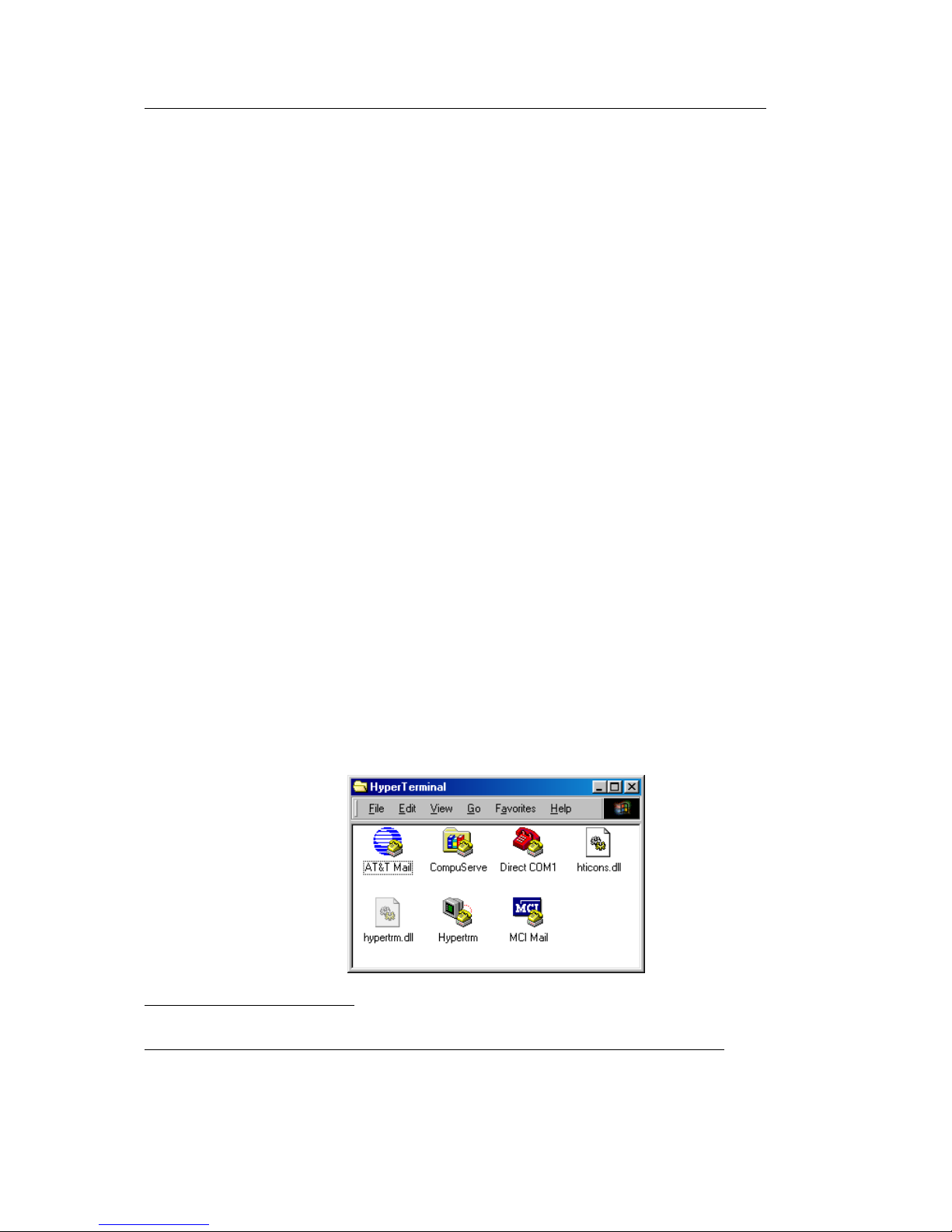
Start the HyperTerminal program within the
Programs|Accessories bar.
The HyperTerminal main window will now appear
1
:
1
: The HyperTerminal window has a different appearance for different versions of Windows.

Getting Started
____________________________________________________________________________
Double-click on the HyperTerminal icon “Hypertrm” to create a
new HyperTerminal session.
The Connection Description window will now appear. Enter
“COM Direct” in the Name text field.
Next click on OK. This creates a new HyperTerminal session
named “COM Direct” and advances you to the next
HyperTerminal window.
The COM Direct Properties window will now appear. Specify
Direct to COM1/COM2 under the Connect Using pull-down
menu (be sure to indicate the correct COM setting for your
system).
© PHYTEC Meßtechnik GmbH 2006 L-688e_2
SPS-Kit with phyCORE® phyCORE-MPC5200 QuickStart Instructions
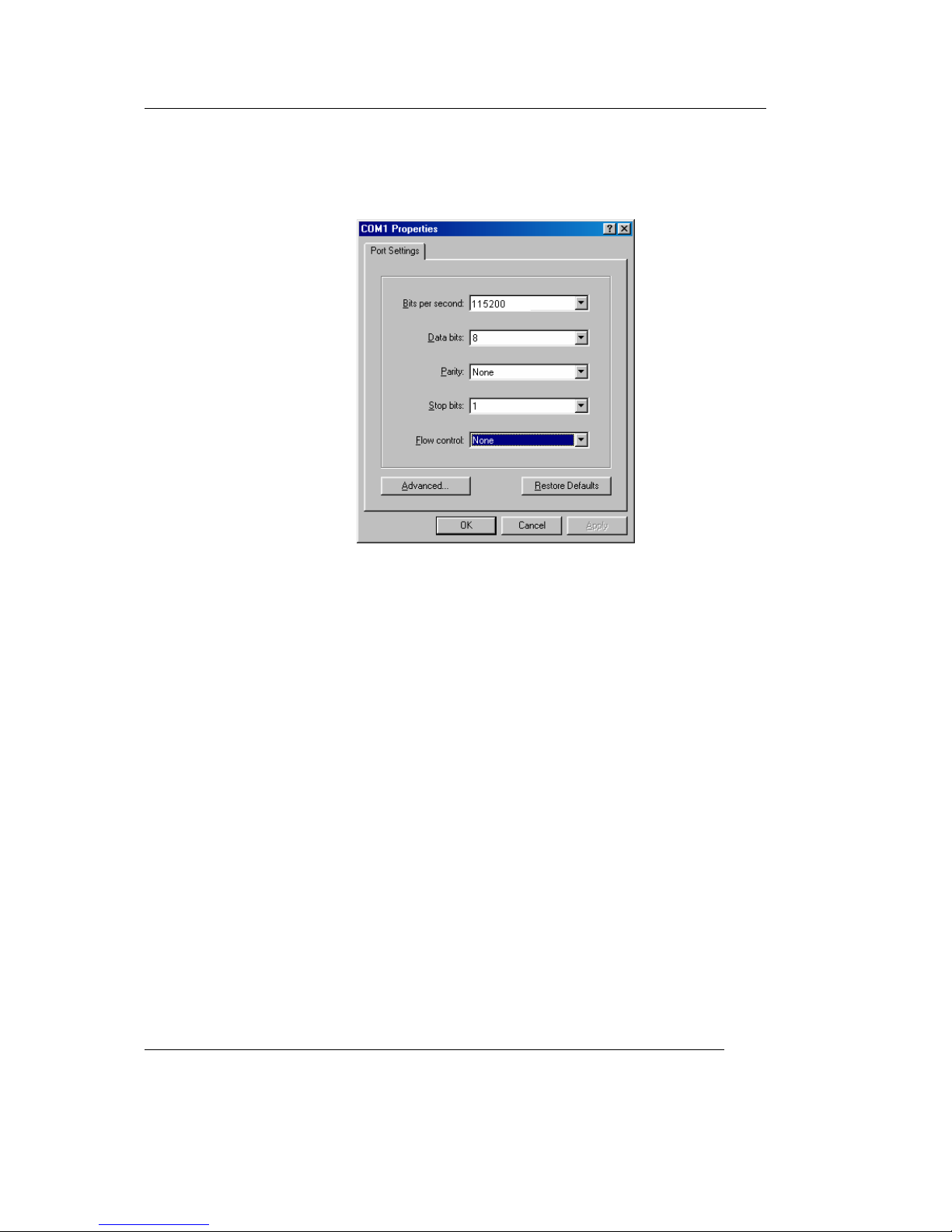
Click the Configure button in the COM Direct Properties
window to advance to the next window (COM1/COM2
Properties).
• Set the following COM parameters: Bits per second = 115200;
Data bits = 8; Parity = None; Stop Bits = 1; Flow Control =
None.
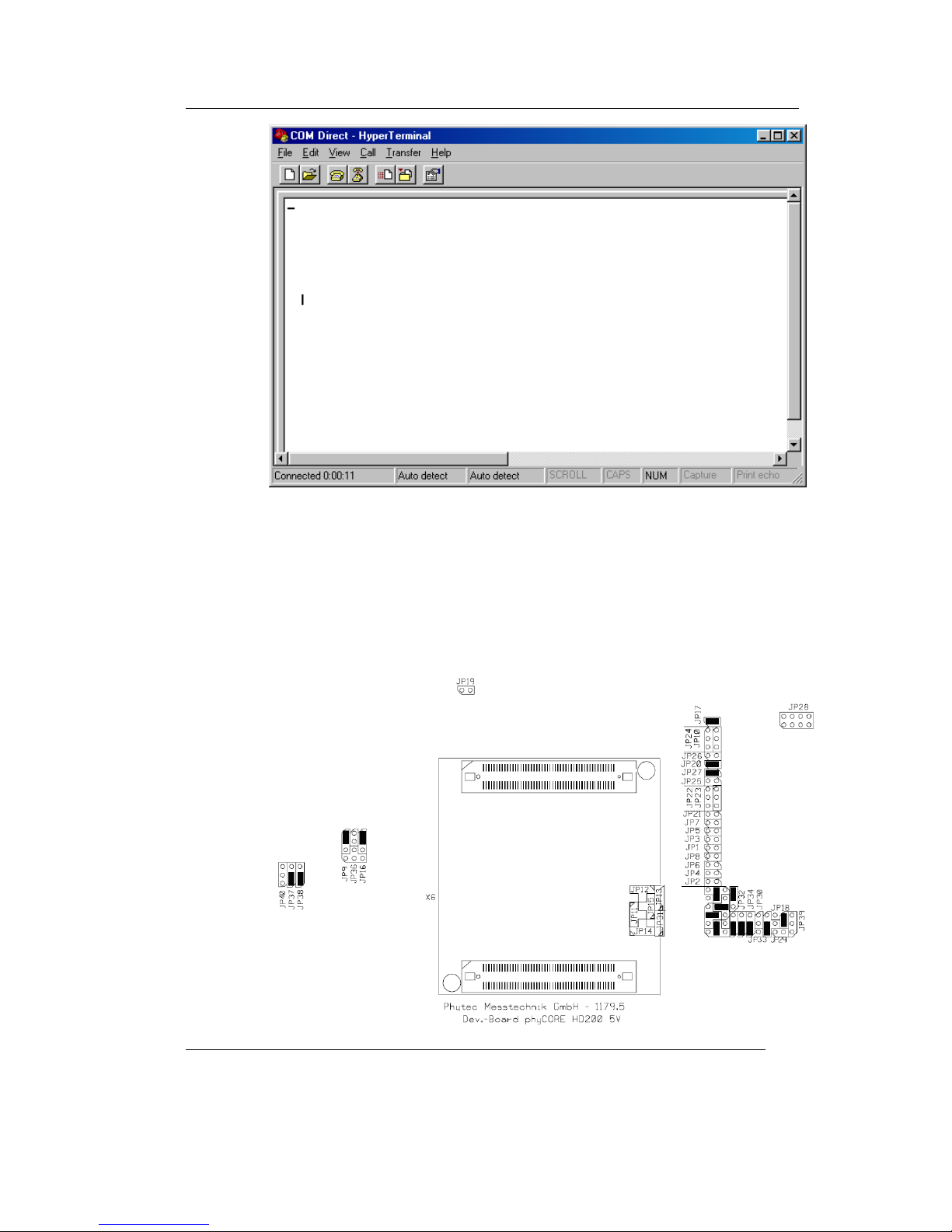
• Selecting OK advances you to the COM Direct–
HyperTerminal monitoring window. Notice the connection
status report in the lower left corner of the window.
© PHYTEC Messtechnik GmbH 2006 L-688e_2
Getting Started
____________________________________________________________________________
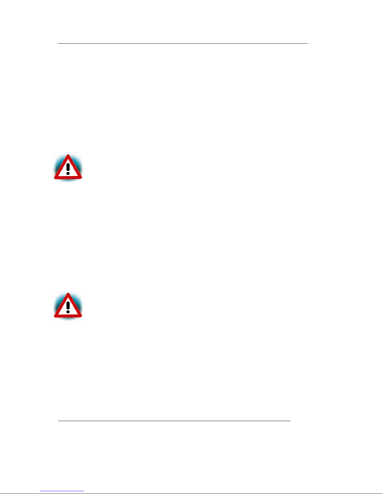
2.2.1 Setting the jumpers on the Development Board
Going through this QuickStart you have to setup some Jumper
settings. You can see the right jumper settings on the following
screenshot. If you don’t have these settings on your board set the
jumper like shown in the screenshot.
© PHYTEC Meßtechnik GmbH 2006 L-688e_2
SPS-Kit with phyCORE® phyCORE-MPC5200 QuickStart Instructions
© PHYTEC Messtechnik GmbH 2006 L-688e_2
•
2.2.2 Connecting the host to the target
In this section you will learn how to connect your host pc with
the target. The connection will be done with a cross-over
Ethernet cable and a serial null modem cable. You will start
Linux from flash on the target and you will be able to login in
Linux over the serial connection with HyperTerminal.
Connect the serial cable with the lower connector P1 on the
target and the serial interface COM1 on your host.
Ensure to use the cable included in this RDK.
.
•
•
•
Connect the cross-over Ethernet cable with the RJ45 connector
of the target and the right network card of your host.
Be sure that HyperTerminal is still open.
Connect the AC adapter with the power supply connector X1
(5V) on your board.
The power connector should have 5 VDC inside and outside
should be ground.
.
After connecting the board with the power supply the target starts
booting. You should see the Linux boot messages in
HyperTerminal When the target finished loading a login prompt
should appear. Type root and enter.

Getting Started
____________________________________________________________________________
2.2.3 Configuring the host
In the following step you will have to configure the IP address of
your host. We recommend disconnecting your host from any
other network. If you change the host IP, problems may occur
with existing hosts.
• On the Windows desktop right-click on Network
Neighbourhood and click Properties.
• Right-click on Local Area Connection and click Properties.
• Select Internet Protocol (TCP/IP) and click Properties.
• In the Internet Protocol (TCP/IP) Properties window, select
Use the following IP address if not already selected and
specify the new IP address you wish to use. Enter
192.168.3.10.
© PHYTEC Meßtechnik GmbH 2006 L-688e_2

SPS-Kit with phyCORE® phyCORE-MPC5200 QuickStart Instructions
• Enter 255.255.255.0 in the Network mask field.
• Close the dialogs.
Your host is now configured so you can access the target via
Ethernet.
2.2.4 Configuring the target
© PHYTEC Messtechnik GmbH 2006 L-688e_2
•
In this section you will learn how to transfer files from your host
PC to the target using windows file explorer and the ftp protocol.
Open the windows file explorer.
• Enter in the address field:
ftp://root@192.168.3.11/

Getting Started
____________________________________________________________________________
When asked for a username type in root. A password is not
required.
© PHYTEC Meßtechnik GmbH 2006 L-688e_2
• Open another windows file explorer
• Change to the directory C:\PHYTEC\SPS-Kit(MPC5200)\RTS
• Click on the file ppc-plclinux_rt and drag it to the explorer
window with the ftp connection
• Click on the file libIODrvTemplate.so and drag it to the
explorer window with the ftp connection.
• Click on the file rts3s.cfg and drag it to the explorer window
with the ftp connection
Starting the run-time system
• Copy the IO driver library in the user/lib directory on the host
In HyperTerminal type
cp libIODrvTemplate.so /usr/lib
• Type ./ppc-plclinux_rt. The run-time system should start
now.
This is only a demo version. The run run-time system will
shutdown after 1 hour.

SPS-Kit with phyCORE® phyCORE-MPC5200 QuickStart Instructions
© PHYTEC Messtechnik GmbH 2006 L-688e_2
2.3 Running the demo application
In this chapter you will learn how to setup your project so it is
automatically downloaded to the target and CodeSys can
communicate with the target application.
• Start CoDeSys
Click on Start/Programs/3S Software/CodeSysV2.3/
CodeSysV2.3
• Open the demo application
Click on File/Open
Navigate to the demo directory
C:\Phytec\SPS-Kit(MPC5200)\Demos\Blinky
Click on the project file Led.pro
• Change the communication parameters
Click on Online/Communication parameters
There is an entry MPC5200 with the setting TCP/IP and the IP
address of the MPC5200. If you use another IP address on the
MPC5200 tiny change the entry so it fits your settings.

Getting Started
____________________________________________________________________________
• Press OK to close the Communication Parameters dialog
• Load the PLC configuration
In the project browser, click on the tab sheet Resources. In
Resources click on PLC Configuration.
In the PLC Configuration dialog should appear a root entry
MPC5200 configuration. To view the configuration for the
I/Os, right click on the root entry, select Append sub element
and click on IO. Now right click on IO, select Append LED.
In the Base parameters dialog enter %QB1234 in the field
Output address.
The PLC Configuration dialog will now look like this
© PHYTEC Meßtechnik GmbH 2006 L-688e_2

SPS-Kit with phyCORE® phyCORE-MPC5200 QuickStart Instructions
There is a variable called LED with the output address %QB1234
that can be used to toggle the LED on the board.
Open the source code by pressing POUs in the project browser.
Double-click on PLC_PRG. Here you can see how the LED is
toggled by referencing the variable %QB1234.
counter:=counter+1;
%QB1234:=counter MOD 2;
• Login in
Online/Login
A dialog appears that not program is on the controller. Press Yes
to download the program.
© PHYTEC Messtechnik GmbH 2006 L-688e_2

Getting Started
____________________________________________________________________________
• Starting the demo
Online/Run
The red led on the MPC5200 carrier board is flashing.
If the LED is not flashing please be sure that J17 on the carrier
board is closed.
Press Online/Logout to stop the demo.
You now have successfully run your first demo application with
CodeSys.
© PHYTEC Meßtechnik GmbH 2006 L-688e_2

SPS-Kit with phyCORE® phyCORE-MPC5200 QuickStart Instructions
3 Getting More Involved
25 min
This chapter shows you how to connect a CAN device to the
MPC5200 and program the CAN device using CoDeSys and
CANOpen.
This CAN demo assumes a Beckhoff BK5150 CANOpen device
connected to CAN0 of the MPC5200. You can also connect other
CANOpen devices. Refer to the hardware manual of your
CANOpen device for proper settings.
3.1 Configuring the demo application
Start CoDeSys if not already open.
Click on File/Open
Navigate to the demo directory
C:\Phytec\SPS-Kit(MPC5200)\Demos\CAN
Click on the project file CanDemo.pro
Change to the tab sheet Resources and click on PLC
Configuration.
Click on the entry Can Device.
© PHYTEC Messtechnik GmbH 2006 L-688e_2

Getting More Involved
____________________________________________________________________________
Bus identifier is the CAN interface on the MPC5200. CAN0 is
the first interface.
Select the tab sheet CAN settings.
© PHYTEC Meßtechnik GmbH 2006 L-688e_2

SPS-Kit with phyCORE® phyCORE-MPC5200 QuickStart Instructions
Node id is the id of the CAN device connected to the MPC5200.
Baud rate is the baud rate with which the connection runs, here
it is set to 500kb/s. You can also select Nodeguarding and
Emergency telegram if it is supported.
Select the tab sheet Default PDO mapping.
On the right side you can see a predefined Send PDO with two
Index entries. These entries refer to the two Index entries in the
Objects list on the left. Both entries are connected to a local
variable in the program PCL_PRG. This means, that every time
the variables c and d are updated a PDO is sent with the value of
the two variables as data.
Click on the PDO 16#1800 entry on the right and press
Properties.
© PHYTEC Messtechnik GmbH 2006 L-688e_2

Getting More Involved
____________________________________________________________________________
The COB-ID is the COB that is used for sending the PDO. It
consists of an offset and the NodeID configured in the CAN
settings tab sheet. Change this value when working with different
CAN devices that expects different COB Id´s.
• Change to the tab sheet POUs in the project browser. Double-
click on PCL_PRG. The source code window for this project
appears.
The program starts with a call to
CanOpenWriteMSG(
wDrvNr:= 0,
dwCanID:= 16#70B,
ucLen:= 2,
bRtrFrame:= TRUE,
pPointer8byte:= 0,
ucByte1:= 0,
ucByte2:= 0 );
Note that you can also send CAN packets directly via a library
call.
The parameters are:
© PHYTEC Meßtechnik GmbH 2006 L-688e_2

SPS-Kit with phyCORE® phyCORE-MPC5200 QuickStart Instructions
wDrvNR: CAN interface
dwCanID: COB Id of the packet
ucLen: number of data bytes to send
bRtr: Remote frame
pPointer8byte: ???
ucByte1: first data byte
ucByte2: second data byte
…
This is used in this example to initialize the CAN device.
The program counts up the two variables c and d. So with every
update cycle there will be a packet transmitted with these values.
Click on Project\Build to generate the program.
© PHYTEC Messtechnik GmbH 2006 L-688e_2
3.2 Starting the demo application
If the run-time system on the target isn’t running type in the
HyperTerminal
./ppc-plclinux_rt
to start the run-time system.
To start the CAN demo, press Online/Login and Online/Run. If
the settings match your hardware devices, the CAN device will
process the CAN messages.
Press Online\Logout to stop the demo.
You have successfully passed the Getting More Involved part of this
QuickStart

Debugging
4 Debugging
30 min
In this chapter you will get a short overview over the debugging
features of CoDeSys. You will learn how to start the debugger,
and set breakpoint. Also we give you a short example for the
CoDeSys visualization.
4.1 Starting the debugger
The demo is already configured running in debug mode. If not,
you can activate the debug mode by clicking on Project/Options.
In the Options dialog click on build and check Debugging.
Start the run-time system on the MPC5200 if not already
running.
Start HyperTerminal, login to the MPC5200 and type
./ppc-plclinux_rt. The run-time system should start now.
Press Online/Login
© PHYTEC Meßtechnik GmbH 2006 L-688e_2

SPS-Kit with phyCORE® phyCORE-MPC5200 QuickStart Instructions
Press Online/Run to start the example. You will see the variable
changes on the right window while the program is running.
4.2 Setting a breakpoint
Set a breakpoint by clicking left of a source code line, for
example in the line with the code
d:=d+1
The program stops. You can now execute a single command by
pressing F8.
© PHYTEC Messtechnik GmbH 2006 L-688e_2

Debugging
© PHYTEC Meßtechnik GmbH 2006 L-688e_2
4.3 Visualization
With the CodeSys integrated visualization tool you can draw
graphical elements and connect them with your program
variables. So the changing of a variable during run-time on the
target will change the graphical look of these elements.
In this chapter you will learn how to draw a graphical element
and to connect it with a variable.
First we will define a Receive PDO that will trigger our
visualization object.
Open the PLC Configuration dialog. Click on CANDevice and
then on the tab sheet Default PDO mapping.
In the drop down box List of mappable objects select Receive.
Click on the button Insert Receive PDO. In the Objects list
open the first index. Select PLC_PRG.a and click on the >>
symbol. The entry is added to the new inserted Receive PDO.
Select the newly created index under the Receive PDO and click
on Properties.

SPS-Kit with phyCORE® phyCORE-MPC5200 QuickStart Instructions
In the field COB-ID enter NodeID + 512 or any other COB Id
your device uses for sending.
You have now configured a receive PDO and connected it to the
local variable a of the PLC_PRG.
Now we have to draw the visualization screen.
Click on the tab sheet Visualization in the project browser.
Select Visualizations with the right mouse button. In the popup
select Add Object. In the following dialog enter a name for this
visualization object, e.g. CanVisu.
We now draw a LED on the visualization screen. Click on the
symbol for the circle
and draw a circle on the screen.
Click on the circle with the right mouse button and select
Configure.
Select Colors and click on the button Inside in Alarm Color.
Select red as the fill color.
Select Variables and enter PLC_PRG.a in the field Change
color.
Close the dialog and save the changes. Click on Project/Rebuild
all to compile the project.
© PHYTEC Messtechnik GmbH 2006 L-688e_2

Debugging
© PHYTEC Meßtechnik GmbH 2006 L-688e_2
Start the run-time system on the target if not already running.
Press Online/Login and then Online/Start. When you now force
your device to send a POD with the specified COB-ID the
program copies the data in this packet in variable a. If the
variable is greater than zero, the LED should become red.
Please refer to the CoDeSys manual for further information about
visualization.

SPS-Kit with phyCORE® phyCORE-MPC5200 QuickStart Instructions
5 Further Information
15 min
This chapter gives you some more informations on how to build your
application for running stand-alone and how to write your own drivers and
integrate them in the run-time system.
5.1 Running your application without the CoDeSys IDE
When your application is ready for production processes, you can
run it as a stand-alone application without the need to have a PC
with CoDeSys running.
For this to work, you have to create a boot project.
Open CoDeSys and the LED.pro demo if not already open.
If the run-time system on the target isn’t running type in the
HyperTerminal
./ppc-plclinux_rt
to start the run-time system.
Press Online/Login
Press Online/Run to start the example.
Now you have to create the bootproject.
Press Online/Create Bootproject.
This will automatically copy all necessary files to the target.
Press Online/Logout.
Press File/Exit to close CoDeSys.
© PHYTEC Messtechnik GmbH 2006 L-688e_2

Further Information
© PHYTEC Meßtechnik GmbH 2006 L-688e_2
5.2
Stop the run-time system by pressing CTRL+C in
HyperTerminal.
Now you can start the run-time system again by typing
./ppc-plclinux_rt
The run-time sytem will now use the boot project files copied
from CoDeSys at startup an run the application. The red led on
the MPC5200 carrier board is flashing.
Starting the program when booting the target
In this passage you will integrate the created boot project into
the start process of the target. When you have finished this part,
the run-time sytem will be started automatically each time you
are starting the target. With the configurations done in the
previous chapter, the run-time system will load and execute the
boot project
.
The run-time system is startet via the autologin tool that is part of
the PHYTEC Linux distribution. You just have to configure the
config file for the autologin tool and start the tool via an
additional entry in the file inittab
The inittab file describes which processes are started at
bootup and during normal operation (e.g. /etc/init.d/boot,
/etc/init.d/rc, gettys...). Init distinguishes multiple runlevels,
each of which can have its own set of processes that are
started.
First you will have to create a start script for the autlogin tool in
/etc/sysconfig.
Change the directory to /etc/sysconfig
cd /etc/sysconfig

SPS-Kit with phyCORE® phyCORE-MPC5200 QuickStart Instructions
© PHYTEC Messtechnik GmbH 2006 L-688e_2
Create and open a new file named autologin.
vi autologin
This will start the vi texteditor with an empty document named
autologin.
Start the insert mode in vi by pressing i. Now you can insert text
in the new document.
Enter the following lines:
USER=root
EXEC=/home/ ppc-plclinux_rt
AUTOLOGIN=yes
Press ESC to leave the insert mode. To save the file and exit vi
press
:x
No you will have to add an entry in inittab
Change to the directory /etc. Type the following command:
cd /etc
Open the file inittab with vi.
vi inittab
In the file, you´ll see the following line:
console::respawn:/sbin/getty –L 11520 /dev/ttyPSC2 vt100
Place the cursor at the end of this line, press i to enter insert
mode of vi and press return.
In the new line enter

Further Information
console::once:/sbin/autologin
This will start the autologin at system boot time.
Press ESC to leave the insert mode. To save the file and exit vi
press
:x
Now you can reboot your system to see if the changes are
working. Push the RESET button (S2) on the MPC5200 to restart
the system. After rebooting, the run-time system should start and
the LED starts flashing.
© PHYTEC Meßtechnik GmbH 2006 L-688e_2
5.3 Writing I/O drivers
It is also possible to write your own drivers and dynamically
include them in the run-time system. You can find the necessary
driver templates and makefile installed on your hard disk in the
folder C:\Phytec\SPS-Kit(MPC5200)\RTS\IODrivers. For this to
work you’ll need a Linux development system. Please refer to the
MPC5200 Linux Kit disc that comes with the SPS Kit. On the
disc you’ll find a quickstart instructions that describes how to
setup the development system.
For more information on writing own drivers in CoDeSys please
refer to the CoDeSys manual.
You have successfully finished this QuickStart.

SPS-Kit with phyCORE® phyCORE-MPC5200 QuickStart Instructions
© PHYTEC Messtechnik GmbH 2006 L-688e_2
6 Summary
This QuickStart Instruction gave a general "Rapid Development
Kit" description, as well as software installation advice and an
example program enabling quick out-of-the box start-up of the
phyCORE
®
-MPC5200 in conjunction with CoDeSys.
In the Getting started section you learned how to configure your
host to provide a basis for working with your target platform.
You installed the Rapid Development Kit software and you
learned to copy and run a program on the target.
In the Getting More Involved section you got a step-by-step
instruction on how to modify the example and copy output files
to the phyCORE –MPC5200 using CoDeSys.
The Debugging part of this QuickStart gave you information on
setting up and using the debugger with CoDeSys. You learned
how to set breakpoints, watching and changing variables content
and use the Visualization feature.

Suggestions for Improvement
© PHYTEC Messtechnik GmbH 2006 L-688e_2
Document: SPS Kit with phyCORE-MPC5200B tiny,
QuickStart Instructions
Document number: L-688_2, November 2006
How would you improve this manual?
Did you find any mistakes in this manual? page
Submitted by:
Customer number:
Name:
Company:
Address:
Return to:
PHYTEC Technologie Holding AG
Postfach 100403
55135 Mainz, Germany
Fax : +49 (6131) 9221-26

Published by
© PHYTEC Messtechnik GmbH 2006 Ordering No. L-688e_2
Printed in Germany
 Loading...