


A product of a PHYTEC Technology Holding company
phyBOARD®-Regor AM335x
Application Guide
Document No.: L-823e_2
SBC Prod. No.: PB-01802-xxx
CB PCB No.: 1447.3
SOM PCB No.: 1358.4
Edition: June 2018

phyBOARD-Regor AM335x [PB-01802-xxx]
EUROPE
NORTH AMERICA
FRANCE
Address:
PHYTEC Messtechnik GmbH
GERMANY
PHYTEC America LLC
USA
PHYTEC France
FRANCE
+49 6131 9221-32
sales@phytec.de
+1 800 278-9913
sales@phytec.com
+33 2 43 29 22 33
info@phytec.fr
Technical Support:
+49 6131 9221-31
support@phytec.de
+1 206 780-9047
support@phytec.com
support@phytec.fr
Fax:
+49 6131 9221-33
+1 206 780-9135
+33 2 43 29 22 34
http://www.phytec.de
http://www.phytec.eu
INDIA
CHINA
Address:
PHYTEC Embedded Pvt. Ltd.
INDIA
PHYTEC Information Technology (Shenzhen) Co. Ltd.
+91-80-4086 7046/49
sales@phytec.in
+86-755-6180-2110
sales@phytec.cn
Technical Support:
+91-80-4086 7047/50
support@phytec.in
support@phytec.cn
Fax:
Copyrighted products are not explicitly indicated in this manual. The absence of the trademark (, or ®)
and copyright (©) symbols does not imply that a product is not protected. Additionally, registered patents
and trademarks are similarly not expressly indicated in this manual.
The information in this document has been carefully checked and is considered to be entirely reliable.
However, PHYTEC Messtechnik GmbH assumes no responsibility for any inaccuracies. PHYTEC Messtechnik
GmbH neither gives any guarantee nor accepts any liability whatsoever for consequential damages
resulting from the use of this manual or its associated product. PHYTEC Messtechnik GmbH reserves the
right to alter the information contained herein without prior notification and accepts no responsibility for
any damages that might result.
Additionally, PHYTEC Messtechnik GmbH offers no guarantee nor accepts any liability for damages arising
from the improper usage or improper installation of the hardware or software. PHYTEC Messtechnik GmbH
further reserves the right to alter the layout and/or design of the hardware without prior notification and
accepts no liability for doing so.
Copyright 2018 PHYTEC Messtechnik GmbH, D-55129 Mainz.
Rights - including those of translation, reprint, broadcast, photomechanical or similar reproduction and
storage or processing in computer systems, in whole or in part - are reserved. No reproduction may occur
without the express written consent from PHYTEC Messtechnik GmbH.
Sales:
Web Site:
Sales:
Robert-Koch-Str. 39
D-55129 Mainz
No. 1688, 25th A Cross
th
27
Main, 2nd Sector, Opp. PEP School V2,
HRS Layout,
Bangalore 560102
203 Parfitt Way SW
Bainbridge Island, WA 98110
http://www.phytec.com http://www.phytec.fr
2106A, Block A, Tianxia Jinniu Square,
Taoyuan Road, Nanshan District,
518026 Shenzhen
CHINA
17, place Saint-Etienne
F-72140 Sillé-le-Guillaume
Web Site: http://www.phytec.in http://www.phytec.cn
2ndEdition June 2018
PHYTEC Messtechnik GmbH 2018 L-823e_2

Contents
List of Figures ................................................................................................... ii
List of Tables ................................................................................................... iii
Conventions, Abbreviations and Acronyms ............................................................. iv
Preface ......................................................................................................... vii
1 Introduction .............................................................................................. 1
1.1 Hardware Overview ........................................................................................ 1
1.1.1 Features of the phyBOARD-Regor AM335x ............................................... 1
1.1.2 Block Diagram ................................................................................... 2
1.1.3 View of the phyBOARD-Regor AM335x .................................................... 3
2 Accessing the phyBOARD-Regor Features .......................................................... 4
2.1 Overview of the phyBOARD-Regor Peripherals ..................................................... 4
2.1.1 Connectors and Pin Header .................................................................. 4
2.1.2 LEDs ................................................................................................ 6
2.1.3 Switches .......................................................................................... 8
2.1.4 Jumpers ........................................................................................... 9
2.2 Functional Components on the phyBOARD-Regor SBC .......................................... 10
2.2.1 Power Supply ................................................................................... 10
2.2.1.1 Power Connector (X1) ........................................................... 10
2.2.1.2 Power LEDs D62, D63, and D68 ............................................... 11
2.2.1.3 Status LEDs D66 and D67 ....................................................... 12
2.2.1.4 Backup Supply ..................................................................... 12
2.2.2 UART Connectivity (X3, X5, X6, X7) ....................................................... 13
2.2.2.1 RS-232 Connectivity (X5)....................................................... 14
2.2.2.2 RS-485 Connectivity (X3)....................................................... 15
2.2.3 CAN Connectivity (X3, JP3) ................................................................. 16
2.2.4 Ethernet Connectivity (X9) ................................................................. 17
2.2.4.1 MAC Address ....................................................................... 17
2.2.5 USB Connectivity (X4, X6) ................................................................... 18
2.2.6 Secure Digital Memory Card/ MultiMedia Card (X11) ................................. 19
2.2.7 Digital GPIOs 1-4 (X2) ........................................................................ 20
2.2.8 Card Edge Connector (X7) ................................................................... 22
2.2.9 Boot Mode (S4) ................................................................................ 23
2.2.10 System Reset Button (S2) ................................................................... 23
2.2.11 RTC ................................................................................................ 24
3 System Level Customizing ........................................................................... 25
3.1 Expansion Connector (X6) ............................................................................. 25
3.1.1 I2C Connectivity ................................................................................ 27
4 Technical Specifications ............................................................................. 28
4.1 Product Power Rating ................................................................................... 29
4.2 Product Temperature Grades .......................................................................... 29
5 Revision History ....................................................................................... 31
Index ............................................................................................................ 32
PHYTEC Messtechnik GmbH 2018 L-823e_2 i

phyBOARD-Regor AM335x [PB-01802-xxx]
List of Figures
Figure 1: Block Diagram of the phyBOARD-Regor AM335x ................................................ 2
Figure 2: View of the phyBOARD-Regor AM335x with phyCORE-AM335x ............................... 3
Figure 3: phyBOARD-Regor AM335x connectors ............................................................. 3
Figure 4: phyBOARD-Regor AM335x LEDs locations ......................................................... 6
Figure 5: phyBOARD-Regor AM335x Switch Locations ...................................................... 8
Figure 6: Power Supply Connector X1 ......................................................................... 10
Figure 7: LEDs D66 and D67 with Switch S2 ................................................................. 12
Figure 9: RS-485 Interface Connector X3 .................................................................... 15
Figure 10: Components supporting the CAN Interface ..................................................... 16
Figure 11: Ethernet Interfaces at Connector X9 .............................................................. 17
Figure 12: USB Interface Connector X4 ........................................................................ 18
Figure 13: MMC/SD Card Interface at Connector X11 ....................................................... 19
Figure 14: Digital GPIOs at Connector X2 ...................................................................... 20
Figure 15: Card Edge Connector X7 .............................................................................. 22
Figure 16: Boot Switch S4 ......................................................................................... 23
Figure 17: System Reset Button S2 .............................................................................. 23
Figure 18: Expansion Connector X6 ............................................................................. 25
ii PHYTEC Messtechnik GmbH 2018 L-823e_2

Contents
List of Tables
Table 1: Abbreviations and Acronyms used in this Manual ................................................v
Table 2: phyBOARD-Regor Connectors and Pin Headers .................................................. 4
Table 3: phyBOARD-Regor LEDs Descriptions ................................................................ 6
Table 3: phyBOARD-Regor LEDs Descritption (continued) ............................................... 7
Table 4: phyBOARD-Regor Switches Description ............................................................ 8
Table 5: phyBOARD-Regor Jumper Description ............................................................. 9
Table 6: Pin Assignment of the 5 position Phoenix Contact MINI COMBICON Base Strip X1 .... 11
Table 7: Connectors and Signal Levels of the UART Interfaces ......................................... 13
Table 8: Pin Assignment of the RS-232 Interface at Connector X5 .................................... 14
Table 9: Pin Assignment of the RS-485 Interface at Connector X3 .................................... 15
Table 10: Pin Assignment of CAN Connector X3 .............................................................. 16
Table 11: Digital input switching levels for GPIO 1-4....................................................... 20
Table 13: Pin Assignment of CardEdge Connector X7....................................................... 22
Table 14: Boot Switch Configuration for S4................................................................... 23
Table 15: Pin Assignment of PHYTEC Expansion Connector X6 ........................................... 25
Table 16: I2C Addresses in Use ................................................................................... 27
Table 17: Power ratings of the phyBOARD-Regor ........................................................... 29
Table 18: Product Temperature Grades ........................................................................ 30
PHYTEC Messtechnik GmbH 2018 L-823e_2 iii

phyBOARD-Regor AM335x [PB-01802-xxx]
Conventions, Abbreviations and Acronyms
This hardware manual describes the PB-01802-xxx Single Board Computer (SBC), hereby
referred to as phyBOARD-Regor AM335x. The manual specifies the
phyBOARD-Regor AM335x's design and function. Precise specifications for the Texas
Instruments AM335x microcontrollers can be found in the Texas Instrument’s
Sheet and Technical Reference Manual
.
Conventions
The conventions used in this manual are as follows:
Signals that are preceded by an "n", "/", or “#”character (e.g.: nRD, /RD, or #RD), or
that have a dash on top of the signal name (e.g.: RD) are designated as active low
signals. That is, their active state is when they are driven low, or are driving low.
A "0" indicates a logic zero or low-level signal, while a "1" represents a logic one or
high-level signal.
2
The hex-numbers given for addresses of I
C devices always represent the 7 MSB of the
address byte. The correct value of the LSB, which depends on the desired command
(read (1), or write (0)), must be added to get the complete address byte. E.g. the given
address in this manual 0x41 => the complete address byte = 0x83 to read from the
device and 0x82 to write to the device.
Tables which describe jumper settings show the default position in bold, blue text.
Text in
blue italic
indicates a hyperlink within, or external to the document. Click these
links to quickly jump to the applicable URL, part, chapter, table, or figure.
AM335x Data
iv PHYTEC Messtechnik GmbH 2018 L-823e_2

Conventions, Abbreviations and Acronyms
A/V
Audio/Video
BSP
Board Support Package (Software delivered with the Development Kit
the module and Development Tools)
CB
Carrier Board; used in reference to the phyBOARD-Regor Development
Kit Carrier Board
DFF
D flip-flop
DSC
Direct Solder Connect
EMB
External memory bus
EMI
Electromagnetic Interference
GPI
General purpose input
GPIO
General purpose input and output
GPO
General purpose output
IRAM
Internal RAM; the internal static RAM on the Texas Instruments AM335x microcontroller
J
Solder jumper; these types of jumpers require solder equipment to remove and place
JP
Solderless jumper; these types of jumpers can be removed and placed by hand with no special tools
NC
Not Connected
NM
Not Mounted
NS
Not Specified
PCB
Printed circuit board
PDI
PHYTEC Display Interface; defined to connect PHYTEC display adapter boards or custom adapters
PEB
PHYTEC Expansion Board
PMIC
Power management IC
PoE
Power over Ethernet
PoP
Package on Package
POR
Power-on reset
RTC
Real-time clock
SBC
Single Board Computer; used in reference to the PBA-CD-02
/phyBOARD-Regor AM335x
SMT
Surface mount technology
SOM
System on Module; used in reference to the PCL-051
/phyCORE-AM335x module
Abbreviations and Acronyms
Many acronyms and abbreviations are used throughout this manual. Use
Table 1
to
navigate unfamiliar terms used in this document.
Abbreviation Definition
including an operating system (Windows, or Linux) pre-installed on
Table 1: Abbreviations and Acronyms used in this Manual
PHYTEC Messtechnik GmbH 2018 L-823e_2 v

phyBOARD-Regor AM335x [PB-01802-xxx]
Abbreviation
Definition
Sx
User button Sx (e.g. S1, S2) refers to the available user buttons or DIP switches on the CB
Sx_y
Switch y of DIP switch Sx; refers to the DIP switch on the carrier board
VSTBY
SOM standby voltage input
, it is possible to
Table 1: Abbreviations and Acronyms used in this Manual (continued)
At this icon you might leave the path of this Application Guide.
This is a warning. It helps you to avoid annoying problems.
You can find useful supplementary information about the topic.
The BSP delivered with the phyBOARD-Regor AM335x usually includes
drivers and/or software for controlling all components such as interfaces,
memory, etc. Therefore, programming close to hardware and register
level is not necessary in most cases. For this reason, this manual contains
no detailed description of the controller’s registers. Please refer to the
AM335x Technical Reference Manual
if such information is needed to
connect customer designed applications
Beginning with BSP version AM335x-PD14.1-rc1
configure the BSP in regards to the hardware configuration. This allows
the user to easily adapt the BSP if an expansion board is attached,
removed or exchanged.
vi PHYTEC Messtechnik GmbH 2018 L-823e_2

Preface
Preface
As a member of PHYTEC's new phyBOARD® product family, the phyBOARD-Regor AM335x is
one of a series of PHYTEC System on Modules (SBCs) that offer off-the-shelf solutions for a
huge variety of industrial applications. The new phyBOARD
series of extremely compact embedded control engines featuring various processing
performance classes. All phyBOARDs are rated for industry, cost optimized, and offer longterm availability. The phyBOARD-Regor AM335x is one of currently six industrial-grade
carrier boards which are suitable for series production and that have been realized in
accordance with PHYTEC's new SBCplus concept. It is an excellent example of this concept.
For easy implementation into industrial control system racks, the
phyBOARD-Regor AM335x comes in a housing with integrated DIN-Rail sockets.
Furthermore, the board is equipped with connectors allowing for interconnection to
commonly used industrial interfaces.
SBCplus Concept
The SBCplus concept was developed to meet many slight differences in customer requirements with little development effort and thus greatly reduce the time-to-market.
The core of the SBCplus concept is the SBC design library (a kind of construction set) that
consists of a great number of function blocks (so-called "building blocks") which are
constantly refined. The recombination of these function blocks allows PHYTEC to develop a
customer specific SBC within a short time. Thus, PHYTEC is able to deliver production-ready
custom Single Board Computers within a few weeks at very low costs.
The already developed SBCs, such as the phyBOARD-Regor, each represent an intersection
of different customer wishes. Because of this, all necessary interfaces are already available
on the standard versions. This allows the user to integrate the phyBOARD in a large number
of applications without modification. For any necessary detail adjustments, extension
connectors are available to enable adding a wide variety of functions.
Customized Expandability from PHYTEC
Common interface signals route to standard connector interfaces on the carrier board such
as Ethernet, CAN, RS-232, and audio. Due to the easily modifiable phyBOARD design
approach (see "
SBCplus concept
"), these plug-and-play interfaces can be readily adapted
into customer-specific variants according to end system requirements.
®
product family consists of a
PHYTEC Messtechnik GmbH 2018 L-823e_2 vii

phyBOARD-Regor AM335x [PB-01802-xxx]
OEM Implementation
Implementation of an OEM-able SBC subassembly as the "core" of an embedded design
allows for increased focus on hardware peripherals and firmware without expending
resources to "re-invent" microcontroller circuitry. Furthermore, much of the value of the
®
phyBOARD
SBC lies in its layout and test.
Software Support
Production-ready Board Support Packages (BSPs) and Design Services for our hardware will further reduce development time and risk, while at the same time allowing for increased focus on the product expertise.
viii PHYTEC Messtechnik GmbH 2018 L-823e_2

Preface
Ordering Information
Ordering numbers:
phyBOARD-Regor AM335x Development Kit: KPB-01802-xxx
phyBOARD-Regor AM335x SBC:
PB-01802-xxx
Product Specific Information and Technical Support
In order to receive product specific information on all future changes and updates, we recommend registering at:
http://www.phytec.de/de/support/registrierung.html or http://www.phytec.eu/europe/support/registration.html
For technical support and additional information concerning your product, please visit the
phyBOARD-Regor section of our web site which provides product specific information,
such as errata sheets, application notes, FAQs, etc.
http://www.phytec.de/produkt/single-board-computer/phyboard-regor/
Other Products and Development Support
Aside of the new phyBOARD® family, PHYTEC supports a variety of 8-/16- and 32-bit controllers in two ways:
(1) as the basis for Rapid Development Kits which serve as a reference and evaluation
platform
(2) as insert-ready, fully functional OEM modules, which can be embedded directly into
the user’s peripheral hardware design.
Take advantage of PHYTEC products to shorten time-to-market, reduce development costs,
and avoid substantial design issues and risks. With this new innovative full system
solution, new ideas can be brought to market in the most timely and cost-efficient manner.
For more information go to:
http://www.phytec.de/de/leistungen/entwicklungsunterstuetzung.html or www.phytec.eu/europe/oem-integration/evaluation-start-up.html
PHYTEC Messtechnik GmbH 2018 L-823e_2 ix

phyBOARD-Regor AM335x [PB-01802-xxx]
unpacked, handled or operated in
trained personnel (such as electricians, technicians and engineers)
not be operated without protection circuitry if connections to the
Declaration of Electro Magnetic Conformity of the PHYTEC
phyBOARD-Regor AM335x
PHYTEC Single Board Computers (henceforth products) are designed for
installation in electrical appliances, as part of custom applications, or as dedicated
Evaluation Boards (i.e. for use as a test and prototype platform for hardware/software
development) in laboratory environments.
PHYTEC products lacking protective enclosures are subject to damage by
ESD and, therefore, must be
environments in which sufficient precautionary measures have been take
in respect to ESD dangers. It is also necessary that only appropriately
handle and/or operate these products. Moreover, PHYTEC products should
product’s pin header rows are longer then 3m.
PHYTEC products fulfill the norms of the European Union’s Directive for Electro Magnetic
Conformity only in accordance with the descriptions and rules of usage indicated in this
hardware manual (particularly in respect to the pin header row connectors, power
connector and serial interface to a host-PC).
Implementation of PHYTEC products into target devices, as well as user modifications and
extensions of PHYTEC products, is subject to renewed establishment of conformity to, and
certification of, Electro Magnetic Directives. Users should ensure conformance following
any modifications to the products as well as implementation of the products into target
systems.
x PHYTEC Messtechnik GmbH 2018 L-823e_2

Preface
Product Change Management and information in this manual on parts populated on the SOM / SBC
With the purchace of a PHYTEC SOM / SBC, you will, in addition to our HW and SW offerings, receive free obsolescence maintenance service for the HW we provide.
Our PCM (Product Change Management) Team of developers, is continuously processing all incoming PCN's (Product Change Notifications) from vendors and distributors concerning parts which are used in our products.
Possible impacts to the functionality of our products, due to changes of functionality or obsolesce of a certain part, are constantly being evaluated in order to take the right measures in purchasing or within our HW/SW design.
Our general philosophy here is: We never discontinue a product as long as there is demand for it.
Therefore, we have established a set of methods to fulfill our philosophy:
Avoidance strategies
• Avoid changes by evaluating longevity of parts during design in phase.
• Ensure availability of equivalent second source parts.
• Stay in close contact with part vendors to be aware of roadmap strategies.
Change management (in the rare event of an obsolete and non replaceable part)
• Ensure long term availability by stocking parts through last time buy management
according to product forecasts.
• Offer long term frame contract to customers.
Change management (in case of functional changes)
• Avoid impacts on product functionality by choosing equivalent replacement parts.
• Avoid impacts on product functionality by compensating changes through HW redesign
or backward compatible SW maintenance.
• Provide early change notifications concerning functional relevant changes of our
products.
Therefore, we refrain from providing detailed part specific information within this manual, which can be subject to continuous changes, due to part maintenance for our products.
In order to receive reliable, up to date, and detailed information concerning parts used for our product, please contact our support team through the contact information given within this manual.
PHYTEC Messtechnik GmbH 2018 L-823e_2 xi

phyBOARD-Regor AM335x [PB-01802-xxx]
xii PHYTEC Messtechnik GmbH 2018 L-823e_2

Introduction
1 Introduction
1.1 Hardware Overview
The phyBOARD-Regor for phyCORE-AM335x is a low-cost, feature-rich software
development platform supporting the Texas Instruments AM335x microcontroller.
Moreover, due to the numerous standard interfaces, the phyBOARD-Regor AM335x can
serve a foundation for many applications. At the core of the phyBOARD-Regor is the
PCM-051/phyCORE-AM335x System On Module (SOM), containing the processor, DRAM,
NAND Flash, power regulation, supervision, transceivers, and other core functions required
to support the AM335x processor. Surrounding the SOM is the PBA-C-08/phyBOARD-Regor
carrier board, adding power input, buttons, connectors, signal breakout, and Ethernet
connectivity amongst other things.
1.1.1 Features of the phyBOARD-Regor AM335x
The phyBOARD-Regor AM335x supports the following features :
• Developed in accordance with PHYTEC's new SBCplus concept (
Preface
)
• PHYTEC’s phyCORE-AM335x SOM
• Phoenix Contact ME Max 3U1 standard dimensions
• Boot from SD card or NAND Flash
• Max. 1 GHz core clock frequency
• Single supply voltage of 24 V ±10 % via 1×5 position Phoenix Contact MINI COMBICON
connector 3.5 mm) or via Card Edge connector
• Two RJ45 jacks for 10/100 Mbps Ethernet
• Two USB OTG interfaces available (one at USB Micro-AB connector and one at the
expansion connector)
• One Secure Digital / Multi Media Memory Card interface brought out to a Micro-SD
connector
• 2 x RS-232 transceivers supporting UART0 and UART2 with data rates of up to 1 Mbps at
1×5 position Phoenix Contact MINI COMBICON connector 3.5 mm
• RS-485 transceiver supporting UART1 with data rates of up to 1 Mbps at 1×5 position
Phoenix Contact MINI COMBICON connector 3.5 mm
• CAN interface at 1×5 position Phoenix Contact MINI COMBICON connector 3.5 mm
• Reset-Button
• RTC with memory backup capacitor (Gold Capacitor, lasts approx. 7 days)
• Expansion connector with different interfaces
• Card Edge connector to incorporate a DIN rail bus connection
PHYTEC Messtechnik GmbH 2018 L-823e_2 1

phyBOARD-Regor AM335x [PB-01802-xxx]
1.1.2 Block Diagram
Figure 1: Block Diagram of the phyBOARD-Regor AM335x
2 PHYTEC Messtechnik GmbH 2018 L-823e_2

Introduction
1.1.3 View of the phyBOARD-Regor AM335x
Figure 2: View of the phyBOARD-Regor AM335x with phyCORE-AM335x
Figure 3: phyBOARD-Regor AM335x connectors
PHYTEC Messtechnik GmbH 2018 L-823e_2 3

phyBOARD-Regor AM335x [PB-01802-xxx]
Reference
Power supply 12 V – 24 V (1×5 positions Phoenix Contact MINI COMBICON connector 3.5 mm pitch)
4 x digital input/output (1×5 positions Phoenix Contact
CAN / RS-485 connector (UART1) (1×5 positions Phoenix Contact MINI COMBICON connector 3.5 mm pitch)
2.2.2
2.2.3
X4
USB On-The-Go connector (USB Micro-AB)
2.2.5
RS-232 (UART0 and UART2) (1×5 positions Phoenix
Contact MINI COMBICON connector 3.5 mm pitch)
X6
Expansion connector (2×30 socket connector 2 mm pitch)
3.1
Card Edge connector to incorporate DIN rail bus
interface (CAN0)
Ethernet 0/1 connector (dual RJ45 with speed and link LED)
X11
Secure Digital / Multi Media Card (Micro-slot)
2.2.6
phyCORE-Connector (1x50 pin and 1x60 pin Samtec
connector)
2 Accessing the phyBOARD-Regor Features
PHYTEC phyBOARD-Regor is fully equipped with all mechanical and electrical components
necessary for a speedy and secure start-up.
2.1 Overview of the phyBOARD-Regor Peripherals
The phyBOARD-Regor is depicted in
equipped with the components listed in
description of each peripheral, refer to the appropriate chapter listed in the applicable
table.
2.1.1 Connectors and Pin Header
Table 2
the location of each connector for easy identification.
Figure 3
lists all available connectors on the phyBOARD-Regor
Designator
X1
X2
X3
highlights the location of each peripheral for easy identification.
Description See Section
MINI COMBICON connector 3.5 mm pitch)
Figure 2
. It features many different interfaces and is
Table 2
and
Table 3
. Figure 3
. For a more detailed
highlights
2.2.1.1
2.2.7
X5
X7
X9
X64
Table 2: phyBOARD-Regor Connectors and Pin Headers
4 PHYTEC Messtechnik GmbH 2018 L-823e_2
connectivity with RS-485 interface (UART1) or CAN
2.2.2
2.2.8
2.2.4
4

Accessing the phyBOARD-Regor Features
Ensure that all module connections do not exceed their expressed
peripherals.
maximum voltage or current. Maximum signal input values are indicated in
the corresponding controller User's Manual/Data Sheets. As damage from
improper connections can vary according to use and application, it is the
user‘s responsibility to take appropriate safety measures to ensure that the
module connections are protected from overloading through connected
PHYTEC Messtechnik GmbH 2018 L-823e_2 5

phyBOARD-Regor AM335x [PB-01802-xxx]
See
Section
Indicates presence of VBUS for the USB OTG interface at expansion connector X6
Indicates presence of VBUS for the USB OTG interface at USB Micro-AB connector X4
D62
green
5 V voltage generation of the phyBOARD-Regor
3.3 V voltage of the phyBOARD-Regor (approved and
enabled by supply voltage supervisor IC)
2.1.2 LEDs
Figure 4: phyBOARD-Regor AM335x LEDs locations
he phyBOARD-Regor is populated with seven LEDs to indicate the status of the USB VBUS
T
voltages, the power supply voltages, and the RUN/STOP and ERROR status which are visible
through 2 holes in the housing.
Figure 4
LED Color Description
D7 green
D8 green
D63 green
shows the location of the LEDs. Their functions are listed in
Table 3
.
3.1
2.2.5
2.2.1.2
Table 3: phyBOARD-Regor LEDs Descriptions
6 PHYTEC Messtechnik GmbH 2018 L-823e_2

LED Color Description
See
Section
3.3 V voltage on the output of the LDO (has to be
supply the phyBOARD-Regor)
Accessing the phyBOARD-Regor Features
D68 green
approved and enabled by supply voltage supervisor IC to
D66 green RUN/STOP status LED
D67 red ERROR status LED
Table 3: phyBOARD-Regor LEDs Descritption (continued)
2.2.1.2
2.2.1.3
PHYTEC Messtechnik GmbH 2018 L-823e_2 7
phyBOARD-Regor AM335x [PB-01802-xxx]
See
Section
S2
Reset Button
2.2.10
S4
Boot Switch
2.2.9
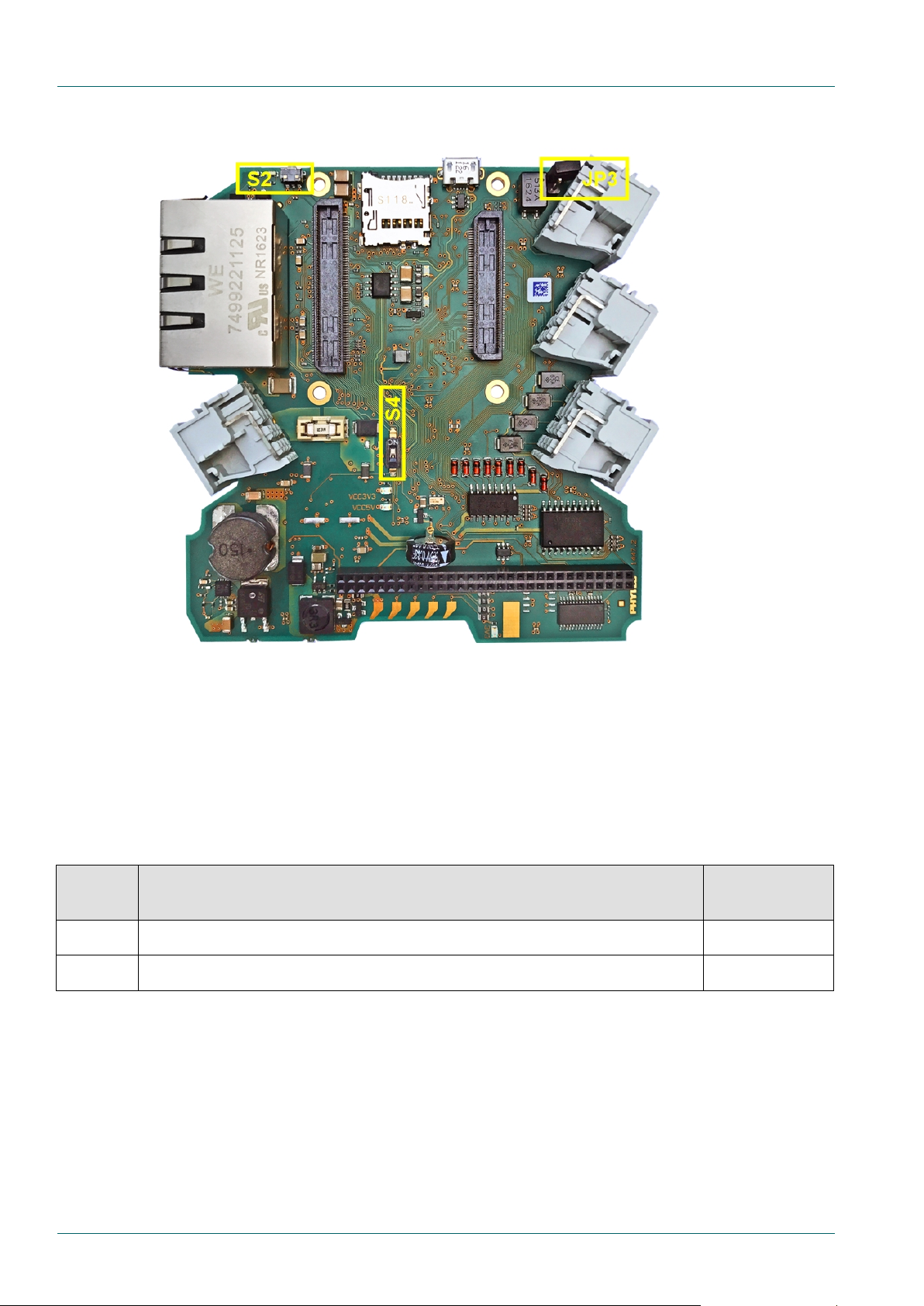
2.1.3 Switches
Figure 5: phyBOARD-Regor AM335x Switch Locations
The phyBOARD-Regor is populated with two switches, one to reset the phyBOARD-Regor
and another to configure the boot sequence.
Figure 5
Switch Description
Table 4: phyBOARD-Regor Switches Description
shows the location of the switches. Their functions are listed in
Table 4
.
8 PHYTEC Messtechnik GmbH 2018 L-823e_2
Accessing the phyBOARD-Regor Features
Due to the small footprint of the solder jumpers (J), PHYTEC does not
team if you need jumper
configurations different from the default configuration.
See
Section
JP3
CAN termination (removable)
2.2.3
J5
Connect RS485-A or CANL signal at pin 5 of connector X7 (fixed)
2.2.8
J6
Connect RS485-B or CANH signal at pin 4 of connector X7 (fixed)
2.2.8
2.1.4 Jumpers
The phyBOARD-Regor comes with one removable jumper (JP) and two solder jumpers (J).
The removable jumper JP3 allows for optional termination of the CAN-interface by the user.
With jumpers J5 and J6, the interface at the Card Edge Connector X7 can be chosen to be a
RS485 (UART1) or a CAN (CAN0) interface.
y default, JP3 is set to terminate the CAN interface. J5 and J6 are set to connect the
B
RS485 interface to the card edge connector X7.
recommend manual jumper modifications. This might also render the
warranty invalid. Because of this, only the removable jumper is described
in this section. Contact the PHYTEC sales
Figure 5
shows the location of the removable jumper JP3. The fixed jumpers J5 and J6 are
placed on the bottom of the PCB. The function of the jumpers on the phyBOARD-Regor are
described in
Table 5
. More detailed information can be found in the appropriate section.
Jumper Description
Table 5: phyBOARD-Regor Jumper Description
Detailed descriptions of the assembled connectors, jumpers and switches can be found in the following sections.
PHYTEC Messtechnik GmbH 2018 L-823e_2 9
phyBOARD-Regor AM335x [PB-01802-xxx]
(F1) is used to protect the
2.2 Functional Components on the phyBOARD-Regor SBC
This section describes the functional components of the phyBOARD-Regor. Each subsection
details a particular connector/interface and associated jumpers for configuring that
interface.
2.2.1 Power Supply
Do not change modules or jumper settings while the phyBOARD-Regor is supplied with power!
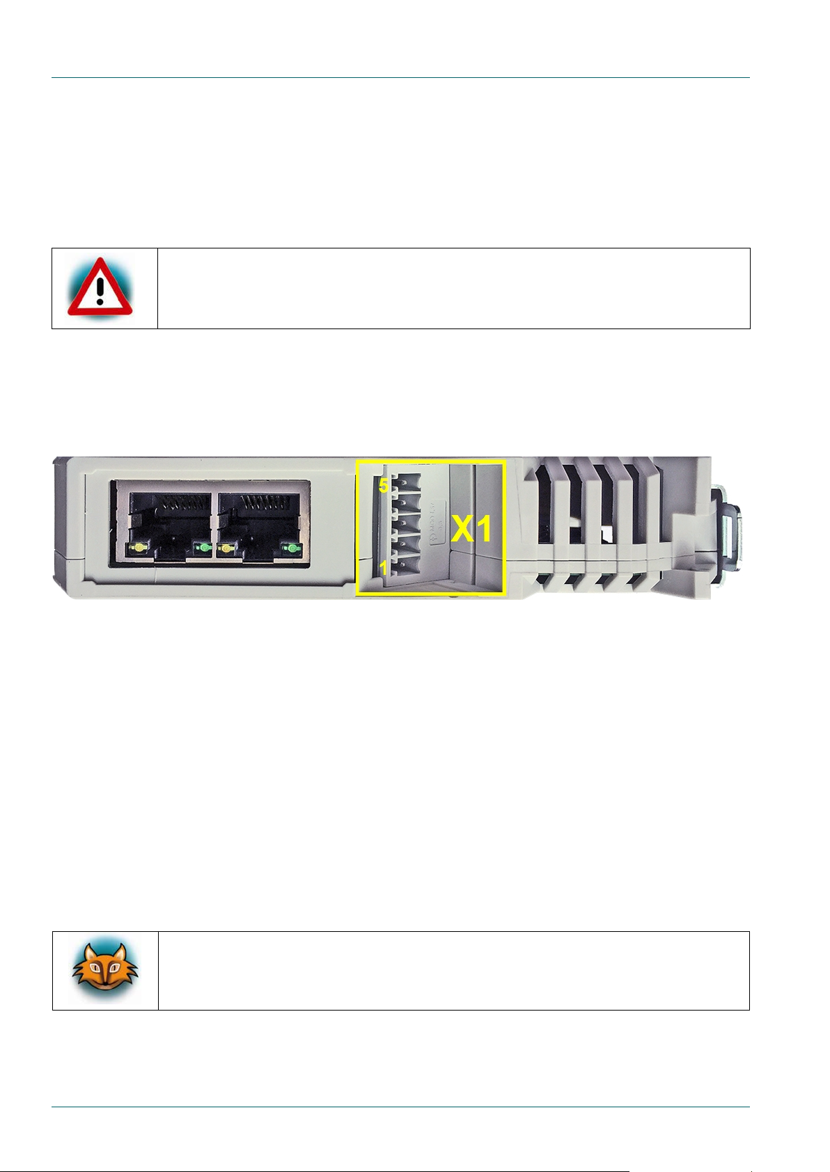
2.2.1.1 Power Connector (X1)
Figure 6: Power Supply Connector X1
The phyBOARD-Regor is equipped with a 5-pole Phoenix Contact MINI COMBICON base strip
3.5 mm connector (X1) suitable for a single 24 V ±10 % supply voltage.
The required current load capacity depends on the specific configuration of the phyCORE
mounted on the phyBOARD-Regor, the particular interfaces enabled while executing
software, as well as whether an optional expansion board is connected to the carrier
board.
The permissible input voltage is +24 V DC ±10 % at the 5-pole Phoenix Contact MINI
COMBICON base strip X1 or, alternatively, at the CARD Edge connector X7 (
section 2.2.8
). A
24 V adapter with a minimum supply of 1A is recommended to supply the board.
A 3A socketed SMD Littelfuse 452
phyBOARD-Regor against over-current.
10 PHYTEC Messtechnik GmbH 2018 L-823e_2

Accessing the phyBOARD-Regor Features
1
X_VIN
+24 V DC ±10 % power supply
2
GND
Ground
3 - NC 4 -
NC 5 -
NC
Figure 6
and
Table 6
show the pin assignment of the connector X1.
Pin Signal Description
Table 6: Pin Assignment of the 5 position Phoenix Contact MINI COMBICON Base Strip X1
2.2.1.2 Power LEDs D62, D63, and D68
The LEDs D62,D63, and D68 indicate the presence of the 3.3 V (D63, D68) and 5 V (D62) supply voltage generated from the input voltage.
he presence of the 3.3 V voltage generated by the LDO is indicated by D68. This voltage is
T
verified by a voltage supervisor IC and is interconnected to the phyBOARD-Regor to supply
its components. The presence of the approved 3.3 V phyBOARD-Regor supply voltage is
indicated by D63.
Figure 4
shows the locations of the three LEDs.
PHYTEC Messtechnik GmbH 2018 L-823e_2 11

phyBOARD-Regor AM335x [PB-01802-xxx]
2.2.1.3 Status LEDs D66 and D67
Figure 7: LEDs D66 and D67 with Switch S2
he status-LEDs D66 and D67 are located next to the reset button and are visible at the
T
front of the housing.
D D66 indicates the RUN/STOP status of the phyBOARD-Regor. This LED is green and can
LE
be used to show if the module is currently running.
T
he ERROR-LED D67 is red and can be used to indicate if there is an error with the module.
Figure 4
2.2.1.4 Backup Supply
The phyBOARD-Regor is equipped with a Gold Capacitor (C339 placed next to connector X6)
which is intended to back up the external RTC (
source is also connected to the backup voltage pin VBAT (A2) of the phyCORE-AM335x and
supplies the module's RTC and some critical registers of the Power Management IC when
the primary system power, X_VIN, is removed. The backup supply lasts approximately 7
days.
and
Figure 7
show the location of the two LEDs.
section 2.2.11
) on the SBC. This voltage
12 PHYTEC Messtechnik GmbH 2018 L-823e_2

Accessing the phyBOARD-Regor Features
Signal
level
See
Section
X5 (1×5 positions Phoenix Contact MINI COMBICON
connector 3.5 mm pitch)
X5 (1×5 positions Phoenix Contact MINI COMBICON
UART3
X6 (2×30 socket connector 2 mm pitch)
TTL
3.1
2.2.2 UART Connectivity (X3, X5, X6, X7)
The AM335x SOM supports up to 6 so called UART units. The phyBOARD-Regor provides the
interfaces of UART0 to UART3 on various connectors at different signal levels.
an overview of the UART signals' availability, locations and signal levels.
or a more detailed description of each serial interface, refer to the appropriate chapter
F
listed in the table.
UART Connector
Table 7
gives
UART0 (standard console)
UART1
UART2
Table 7: Connectors and Signal Levels of the UART Interfaces
connector 3.5 mm pitch)
X6 (2×30 socket connector 2 mm pitch) TTL
X3 (1×5 positions Phoenix Contact MINI COMBICON
X7 (Card Edge connector) RS-485
connector 3.5 mm pitch)
X6 (2×30 socket connector 2 mm pitch) TTL
RS-232
RS-485
RS-232
2.2.2.1
3.1
2.2.2.2
2.2.8
2.2.2.1
3.1
PHYTEC Messtechnik GmbH 2018 L-823e_2 13

phyBOARD-Regor AM335x [PB-01802-xxx]
UART0 serial receive signal RS-232 level (receive signal from
peripheral device at phyBOARD-Regor)
UART0 serial transmit signal RS-232 level (send signal to
peripheral device from phyBOARD-Regor)
3
GND
Ground
UART2 serial receive signal RS-232 level (receive signal from
peripheral device at phyBOARD-Regor)
UART2 serial transmit signal RS-232 level (send signal to
2.2.2.1 RS-232 Connectivity (X5)
Figure 8: RS-232 Interface Connector X5
Two RS-232 transceivers on the phyBOARD-Regor convert the TTL level signals of UART0
(the standard console) and UART2 from the phyCORE-AM335x to RS-232 level signals. The
RS-232 level signals are available at the Phoenix Contact MINI COMBICON connector X5
(5 positions, 3.5 mm pitch).
Connector X5 is located on the right side of the board (
view of the X5 connector.
Table 8
shows the pin assignment of X5. The pin-description in
Figure 2). Figure 8
shows a detailed
the table is given from the perspective of the phyBOARD-Regor.
The UART0 interface serves as the standard console output of the phyCORE-AM335x module
on the phyBOARD-Regor. The initial setting of the UART0 interface is specified to a baudrate of 115200 baud with 8N1 configuration (8 data bits, no parity bit, 1 stop bit).
Pin Signal Description
1 UART0_RXD_RS232
2 UART0_TXD_RS232
4 UART2_RXD_RS232
5 UART2_TXD_RS232
Table 8: Pin Assignment of the RS-232 Interface at Connector X5
peripheral device from phyBOARD-Regor)
14 PHYTEC Messtechnik GmbH 2018 L-823e_2

Accessing the phyBOARD-Regor Features
1
X_UART1_RS485_A
UART1 serial A signal RS-485 level
2
X_UART1_RS485_B
UART1 serial B signal RS-485 level
3
GND
Ground
4
X_CANH
CAN High signal CAN1
5
X_CANL
CAN Low signal CAN1
2.2.2.2 RS-485 Connectivity (X3)
Figure 9: RS-485 Interface Connector X3
n RS-485 transceiver on the phyBOARD-Regor converts the TTL level signals of UART1
A
from the phyCORE-AM335x to RS-485 level signals. The RS-485 level signals are available
at the Phoenix Contact MINI COMBICON connector X3 (5 positions, 3.5 mm pitch).
onnector X3 is located on the right side of the board (
C
view of the X3 connector.
Table 9
shows the pin assignment of X3.
Figure 2
).
Figure 9
shows a detailed
n case jumpers J5 and J6 (
I
section 2.1.4
) are set to the respective positions, the RS-485
level signals are also available at the card edge connector X7 (
Pin Signal Description
Table 9: Pin Assignment of the RS-485 Interface at Connector X3
section 2.2.8
).
PHYTEC Messtechnik GmbH 2018 L-823e_2 15

phyBOARD-Regor AM335x [PB-01802-xxx]
1
X_UART1_RS485_A
UART1 serial A signal RS-485 level
2
X_UART1_RS485_B
UART1 serial B signal RS-485 level
3
GND
Ground
4
X_CANH
CAN High signal line
5
X_CANL
CAN Low signal line
2.2.3 CAN Connectivity (X3, JP3)
Figure 10: Components supporting the CAN Interface
The Controller Area Network (CAN) bus offers a low-bandwidth, prioritized message
fieldbus for serial communication between microcontrollers. It efficiently supports
distributed real time control with a high level of security. The DCAN module of the AM335x
implements the CAN protocol according to the CAN 2.0B protocol specification and
supports bit rates up to 1 Mbit/s. The CAN interface of the phyBOARD-Regor AM335x is
connected to the CAN-controller DCAN1 of the AM335x SOM.
T
he CAN interface of the phyBOARD-Regor AM335x is accessible at the Phoenix Contact
MINI COMBICON connector X3 (5 positions, 3.5 mm pitch as shown in
jumpers J5 and J6 (
signals are also available at the card edge connector X7 (
(
section 2.1.4
lines if needed.
Table 10
Pin Signal Description
Table 10: Pin Assignment of CAN Connector X3
) can be installed to add a 120 Ohm termination resistor across the CAN data
shows the signal mapping of the CAN signals at connector X3.
section 2.1.4
) are set to the respective positions, the CAN interface
section 2.2.8
Figure 10
). In case
). Jumper JP3
epending on the muxing options, a second CAN interface (DCAN0 of the
D
phyCORE-AM335x) is available on expansion port X6 (
be used instead of UART0 (RX and TX) or MMC2 (DAT1 and DAT2).
16 PHYTEC Messtechnik GmbH 2018 L-823e_2
section 3.1
). DCAN0 (TX and RX) can

Accessing the phyBOARD-Regor Features
2.2.4 Ethernet Connectivity (X9)
Figure 11: Ethernet Interfaces at Connector X9
The Ethernet interfaces of the phyBOARD-Regor are accessible at dual RJ45 connectors X9A (Ethernet 0) and X9B (Ethernet 1).
Both Ethernet interfaces are configured as 10/100Base-T networks. The LEDs for LINK
(green) and SPEED (yellow) indication are integrated in the connector. Both Ethernet
transceivers support HP Auto-MDIX, eliminating the need for a direct connect LAN or a
cross-over path cable. They detect the TX and RX pins of the connected device and
automatically configure the PHY TX and RX pins accordingly.
2.2.4.1 MAC Address
In a computer network such as a local area network (LAN), the MAC (Media Access Control)
address is a unique computer hardware number. For a connection to the Internet, a table is
used to convert the assigned IP number to the hardware’s MAC address.
In order to guarantee that the MAC address is unique, all addresses are managed in a central location. The MAC address of the phyBOARD-Regor is saved on the CPU (AM335x).
PHYTEC Messtechnik GmbH 2018 L-823e_2 17

phyBOARD-Regor AM335x [PB-01802-xxx]
Due to the small footprint of the resistors, PHYTEC does not recommend
from the default configuration.
2.2.5 USB Connectivity (X4, X6)
Figure 12: USB Interface Connector X4
he phyBOARD-Regor provides two USB OTG interfaces.
T
SB0 is accessible at connector X4 (USB Micro-AB) located at the top of the
U
phyBOARD-Regor (
3.1
). Both interfaces are configured as USB OTG and are compliant with USB revision 2.0.
USB OTG devices are capable of initiating a session, controlling the connection, and
exchanging host and peripheral roles between each other.
Figure 2
), whereas USB1 is available at expansion connector X6 (
section
wo resistors configure the OTG operating mode. By default, the USB0_ ID pin is left
T
floating, thereby configuring the OTG interface at X4 as slave. USB1_ID is connected to
GND, and configures the OTG interface at expansion connector X6 as host. Typically,
configuring a connecting device as host or slave is done automatically via a USB OTG cable.
However, given the limited number of OTG enabled devices in the embedded market, these
resistors are provided to either simulate an OTG cable, or force the OTG interface into host
mode when OTG operation is not required.
LED D8 displays the status of USB0_VBUS at connector X4 and LED D7 displays the status of
USB1_VBUS at expansion connector X6.
manual jumper modifications. This might also render the warranty invalid.
Contact the PHYTEC sales team if you need USB configurations different
Figure 4
shows the location of the two LEDs.
18 PHYTEC Messtechnik GmbH 2018 L-823e_2

Accessing the phyBOARD-Regor Features
2.2.6 Secure Digital Memory Card/ MultiMedia Card (X11)
Figure 13: MMC/SD Card Interface at Connector X11
The phyBOARD-Regor provides a standard microSDHC card slot at X11 for connection to
MMC/SD interface cards. It allows for an easy and convenient connection to peripheral
devices like SD and MMC cards. Power to the SD interface is supplied by inserting the
appropriate card into the MMC/SD connector which features card detection, a lock
mechanism and a smooth extraction function by Push-in/ Push-out of card.
Ensure that the device is not unplugged while it is still mounted. This may result in data loss!
DIP switch S4 allows the device to toggle between booting from NAND or SD card. In order
to boot from an SD card, S4 must be switched ON (refer to
section 2.1.3
for further
information).
PHYTEC Messtechnik GmbH 2018 L-823e_2 19

phyBOARD-Regor AM335x [PB-01802-xxx]
Please consider that the GPIOs do not have a separate current-driver on
Signal Level
Voltage
H-Level
>11 V
L-Level
<5 V
2.2.7 Digital GPIOs 1-4 (X2)
Figure 14: Digital GPIOs at Connector X2
The phyBOARD-Regor provides four digital IOs that are designed for processing DC-signals
with up to 24 V DC. The digital output voltage depends on the input voltage of the board.
Input and output signals are routed to the CPU (AM335x) through two discrete
optocouplers for galvanic isolation. Thus, it is possible to write and read the status of every
single GPIO of the phyBOARD-Regor simultaneously.
board. In case the GPIOs are used as outputs, the current is self-limited by
the output-optocoupler and should not exceed 750mA for each GPIO
channel. These outputs are low-side outputs.
When the GPIOs on the phyBOARD-Regor are used as digital inputs, they are configured active high with the following switching voltages:
Table 11: Digital input switching levels for GPIO 1-4
20 PHYTEC Messtechnik GmbH 2018 L-823e_2

Accessing the phyBOARD-Regor Features
Digital Input/Output
Digital Input/Output (connects to GPIO0_26 (IN) and GPIO1_14 (OUT) of the AM335x)
Digital Input/Output (connects to GPIO0_23 (IN) and GPIO1_13 (OUT) of the AM335x)
Digital Input/Output (connects to GPIO0_22 (IN) and GPIO1_12 (OUT) of the AM335x)
5
GND
Ground
Table 12
shows the pin assignment of connector X2.
Pin Signal Description
1 DIGIO1
(connects to GPIO0_27 (IN) and GPIO1_15 (OUT) of the AM335x)
2 DIGIO2
3 DIGIO3
4 DIGIO4
Table 12: Pin Assignment of GPIO Connector X2
PHYTEC Messtechnik GmbH 2018 L-823e_2 21
phyBOARD-Regor AM335x [PB-01802-xxx]
Alternative Power supply for the phyBOARD-Regor +24 V DC ±10 %
2
GND
Ground
3
VCC3V3
Power supply for external 3.3 V logic (max. 500 mA)
X_UART1_RS485_A
UART1 serial A signal RS-485 level
X_CANL
CAN Low signal line
X_UART1_RS485_B
UART1 serial B signal RS-485 level
X_CANH
CAN High signal line
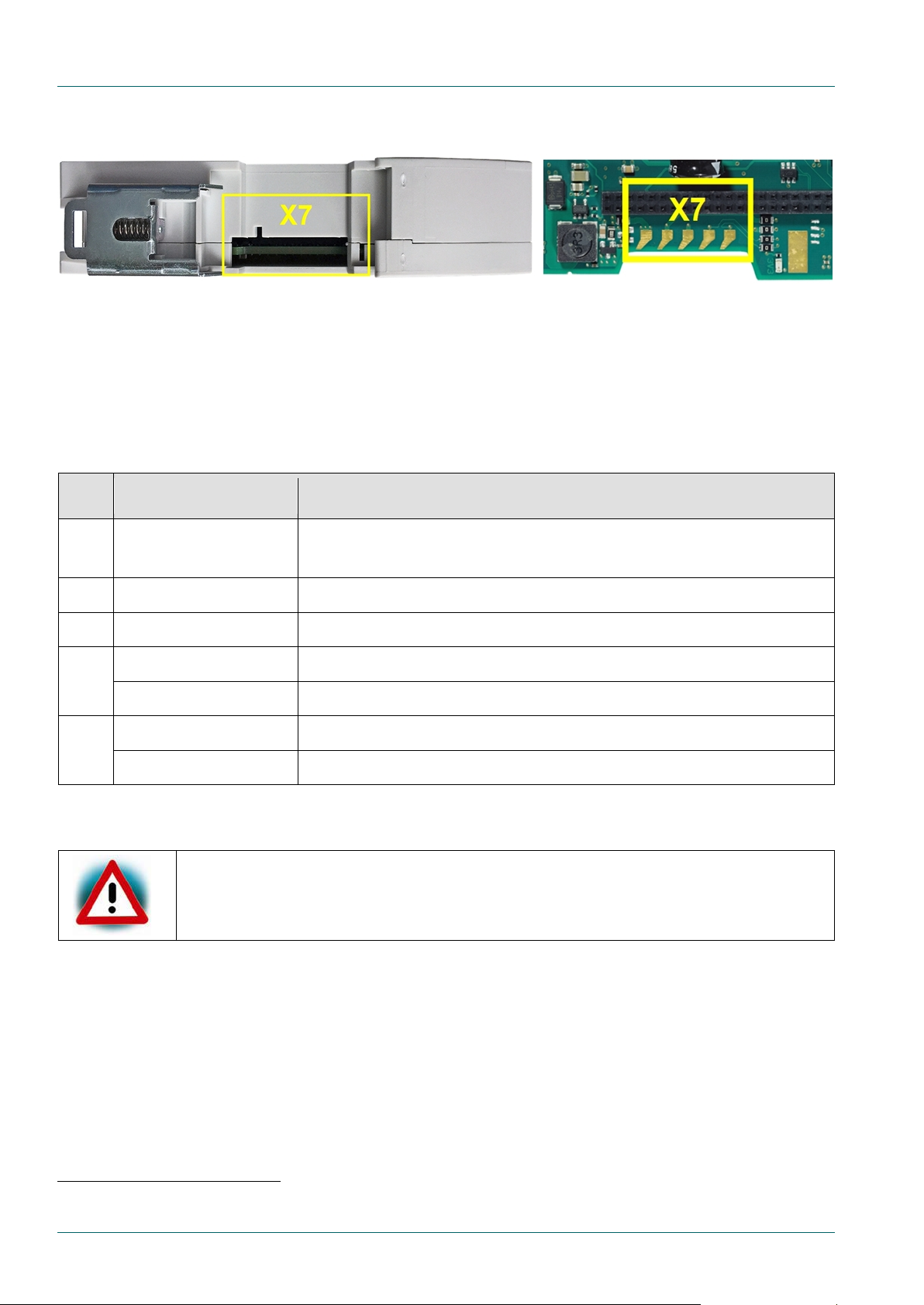
2.2.8 Card Edge Connector (X7)
Figure 15: Card Edge Connector X7
he Card Edge Connector at X7 is a PHYTEC development connector and allows other custom
T
expansion boards or DIN rail bus modules to be connected. The connector can be used as a
RS485 or CAN interface, depending on the position of jumpers J5 and J6 (
As there exists no standard, pay close attention to the pin assignment shown in
section 2.1.4
Table 13
).
.
Pin Signal Description
1 VIN
41
52
Table 13: Pin Assignment of CardEdge Connector X7
If the phyBOARD-Regor is supplied via the card edge connector, there is no protection against overcurrent through fuse F1.
1: The functionality of pin 4 of X7 depend on the jumper J6.
2: The functionality of pin 5 of X7 depend on the jumper J5.
22 PHYTEC Messtechnik GmbH 2018 L-823e_2
Accessing the phyBOARD-Regor Features
Boot Mode
Description
Boot mode 1 (S4 = OFF)
SYSBOOT[4:0] = 10011b → NAND, NANDI2C, MMC0, UART0
Boot mode 2 (S4 = ON)
SYSBOOT[4:0] = 10111b → MMC0, SPI0, UART0, USB
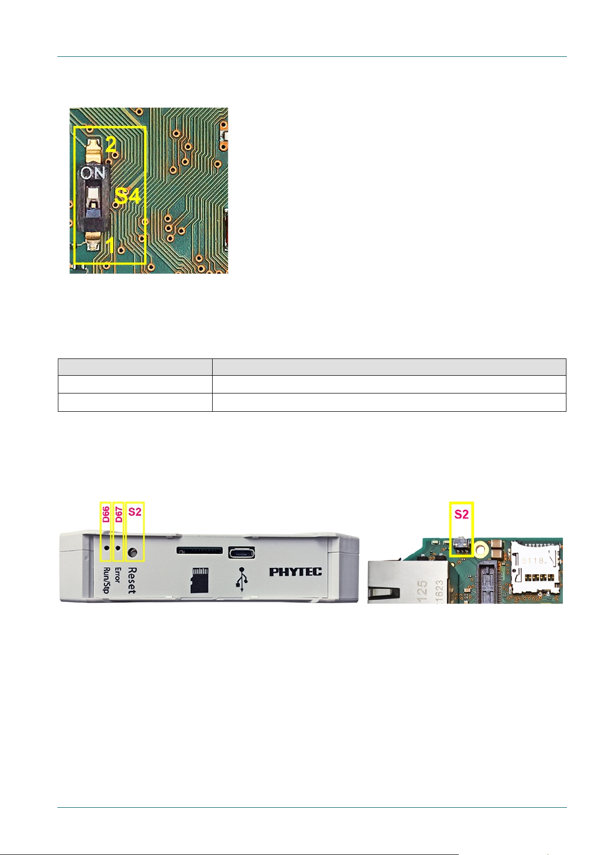
2.2.9 Boot Mode (S4)
Figure 16: Boot Switch S4
The pyhBOARD-Regor has two defined boot sequences which can be selected with DIP switch S4.
Table 14: Boot Switch Configuration for S4
2.2.10 System Reset Button (S2)
Figure 17: System Reset Button S2
The phyBOARD-Regor is equipped with a system reset button at S2. Pressing this button
will toggle the X_nRESET_IN pin (X64A11) of the phyCORE SOM low, causing the module to
reset. Additionally, the reset signal nRESET_OUT is generated on the module and will also
reset the peripherals on the carrier board.
PHYTEC Messtechnik GmbH 2018 L-823e_2 23

phyBOARD-Regor AM335x [PB-01802-xxx]
2.2.11 RTC
The phyBOARD-Regor features an external RTC (RV-4162-C7) as a replacement for the
normally mounted RTC on the phyCORE-AM335x module. It is used for real-time or timedriven applications.
lease note that if the RTC’s interrupt is needed, pin 37 (X_INTR1_GPIO0_20)
P
and pin 40 (X_INT_RTCn) at expansion connector X6 need to be shortcut (
he phyBOARD-Regor is equipped with a Gold Capacitor (C339 placed next to connector X6)
T
which is also intended to back up the external RTC (
section 2.2.1.4
).
section 3.1
).
24 PHYTEC Messtechnik GmbH 2018 L-823e_2

System Level Customizing
Pin #
Signal Name
Type
SL
Description
1
VCC3V3
OUT
3.3 V
3.3 V power supply
2
VCC5V
OUT
5.0 V
5 V power supply
3
VDIG1_1P8V
OUT
1.8 V
1.8 V power supply (max. 300 mA)
4
GND
- - Ground
5
X_SPI0_CS0
OUT
3.3 V
SPI 0 chip select 0
6
X_SPI0_MOSI
OUT
3.3 V
SPI 0 master output/slave input
7
X_SPI0_MISO
IN
3.3 V
SPI 0 master input/slave output
8
X_SPI0_CLK
OUT
3.3 V
SPI 0 clock output
9
GND
- - Ground
UART 0 receive data (standard debug interface)
11
X_I2C0_SDA
I/O
3.3 V
I2C0 Data
UART 0 transmit data (standard debug interface)
13
X_I2C0_SCL
I/O
3.3 V
I2C0 Clock
14
GND
- - Ground
3 System Level Customizing
3.1 Expansion Connector (X6)
Figure 18: Expansion Connector X6
Expansion connector X6 provides an easy way to add other functions and features to the
phyBOARD-Regor. Standard interfaces such as UART, SPI and I
2
C as well as different supply
voltages and some GPIOs are available at the expansion female connector.
The expansion connector is intended to add specific functions with custom expansion boards. This expansion board is developed together with the newest version of the carrier board.
The pinout of the expansion connector is shown in
Table 15
.
10 X_UART0_RXD IN 3.3 V
12 X_UART0_TXD OUT 3.3 V
Table 15: Pin Assignment of PHYTEC Expansion Connector X6
PHYTEC Messtechnik GmbH 2018 L-823e_2 25

phyBOARD-Regor AM335x [PB-01802-xxx]
Pin #
Signal Name
Type
SL
Description
15
X_JTAG_TMS
IN
3.3 V
JTAG Chain Test Mode Select signal
16
X_nJTAG_TRST
IN
3.3 V
JTAG Chain Test Reset (active low)
17
X_JTAG_TDI
IN
3.3 V
JTAG Chain Test Data Input
18
X_JTAG_TDO
OUT
3.3 V
JTAG Chain Test Data Output
19
GND
- - Ground
20
X_JTAG_TCK
IN
3.3 V
JTAG Chain Test Clock signal
21
USB_DP1
I/O
3.3 V
USB data plus USB1
22
USB_DM1
I/O
3.3 V
USB data minus USB1
23
nRESET_OUT
OUT
3.3 V
Reset (active low)
24
GND
- - Ground
25
X_MMC2_CMD
I/O
3.3 V
MMC command3
26
X_MMC2_DAT0
I/O
3.3 V
MMC data 03
27
X_MMC2_CLK
I/O
3.3 V
MMC clock3
28
X_MMC2_DAT1
I/O
3.3 V
MMC data 13
29
GND
- - Ground
30
X_MMC2_DAT2
I/O
3.3 V
MMC data 23
31
X_UART2_RX_GPIO3_9
I/O
3.3 V
UART 2 receive data; GPIO3_94
32
X_MMC2_DAT3
I/O
3.3 V
MMC data 33
33
X_UART2_TX_GPIO3_10
I/O
3.3 V
UART 2 transmit data; GPIO3_104
34
GND
- - Ground
35
X_UART3_RX_GPIO2_18
I/O
3.3 V
UART 3 receive data; GPIO2_184
36
X_UART3_TX_GPIO2_19
I/O
3.3 V
UART 3 transmit data; GPIO2_194
37
X_INTR1_GPIO0_20
I/O
3.3 V
Interrupt 1; GPIO0_20
38
X_GPIO0_7
I/O
3.3 V
GPIO0_7
39
X_AM335_EXT_WAKEUP
IN
3.3 V
External wakeup
40
X_INT_RTCn
OUT
3.3 V
Interrupt from the RTC (active low)
41
GND
- - Ground
42
X_GPIO3_7
I/O
3.3 V
GPIO3_7
43
nRESET_IN
IN
3.3 V
Push-button S2 reset (active low)
44
X_GPIO1_31
I/O
3.3 V
GPIO1_31
45
X_AM335_NMIn
IN
3.3 V
AM335x non-maskable interrupt
Table 15: Pin Assignment of PHYTEC Expansion Connector X6 (continued)
3: These pins are configured as GPIO pins. To use them as MMC/SD card interface, the pin muxing must be changed and
additional software development is required.
4: These pins are configured as GPIO pins. To use them as UART interface, the pin muxing must be changed and additional
software development is required.
26 PHYTEC Messtechnik GmbH 2018 L-823e_2

System Level Customizing
Pin #
Signal Name
Type
SL
Description
46
GND
- - Ground
47
X_AIN4
IN
1.8 V
Analog input 4
48
X_AIN5
IN
1.8 V
Analog input 5
49
X_AIN6
IN
1.8 V
Analog input 6
50
X_AIN7
IN
1.8 V
Analog input 7
51
GND
- - Ground
52
X_GPIO_CKSYNC
I/O
3.3 V
GPIO Clock Synchronization
53
X_USB1_ID
IN
1.8 V
USB1 ID (connected to Ground)
54
USB1_VBUS
OUT
5.0 V
USB bus voltage USB1
55
X_USB1_CE
OUT
3.3 V
USB 1 charger enable
56
GND
- - Ground
57
NC - -
Not connected
Power On for Power Management IC for AM335x
59
GND
- - Ground
60
VCC5V_IN
IN
5.0 V
5 V input supply voltage
Board
Prod. No.
Device
Address used (7 MSB)
EEPROM
0x52
PMIC
0x2D, 0x12
phyBOARD-Regor
PBA-C-08
RTC
0x68
58 X_PB_POWER IN 5.0 V
Table 15: Pin Assignment of PHYTEC Expansion Connector X6 (continued)
If the SPI-NOR Flash on the phyCORE-AM335x is populated, the SPI signals
on the expansion port cannot be used.
3.1.1 I
2
C Connectivity
The I2C interface of the AM335x is available at pin 11 (X_I2C0_SDA) and pin 13
(X_I2C0_SCL) of the expansion connector X6 (
Table 15
).
To avoid any conflicts when connecting external I
addresses of the on-board I
2
C devices must be considered.
2
C devices to the phyBOARD-Regor, the
Table 16
lists the addresses
already in use. This table shows only the default address.
phyCORE-AM335x PCM-051
Table 16: I2C Addresses in Use
PHYTEC Messtechnik GmbH 2018 L-823e_2 27

phyBOARD-Regor AM335x [PB-01802-xxx]
Dimensions:
100 mm x 100 mm
Weight:
129 g
Storage temperature:
-40°C to +85°C
Operating temperature:
refer to
section 4.2
Humidity:
95% r.F. not condensed
Operating voltage:
VCC 24 V +/- 5%
Power consumption:
TBD
4 Technical Specifications
The module’s profile is max. 10 mm thick, with a maximum component height of 3.0 mm on the bottom (connector) of the PCB and approximately 5.0 mm on the top (microcontroller). The board itself is approximately 1.4 mm thick.
n order to design a custom housing for the phyBOARD-Regor, the CAD data of the board is
I
available on our FTP server at:
ftp://ftp.phytec.de/pub/Products/phyBOARD-REGOR-AM335x/
The CAD data of the housing can be found on the web page of Phoenix Contact at:
http://www.phoenixcontact.com/online/portal/us!uri=pxc-ocitemdetail:pid=2201546&library=usen&pcck=P-01-04-02-01&tab=1
Additional specifications:
These specifications describe the standard configuration of the phyBOARD-Regor as of the
printing of this manual.
Connectors on the phyBOARD-Regor:
X1: Manufacturer Phoenix Contact
MCO 1,5/ 5-G1L-3,5 KMGY - 2278380
X2, X3, X5: Manufacturer Phoenix Contact
MCO 1,5/ 5-G1R-3,5 KMGY - 2278351
Mating Connector
or X1, X2, X3, X5: Manufacturer Phoenix Contact
f
MC 1,5/ 5-ST-3,5 GY7035 - 1769087
hytec article number: GP354
P
Please refer to the corresponding data sheets and mechanical specifications provided by
Phoenix Contact® (
www.phoenixcontact.com
).
28 PHYTEC Messtechnik GmbH 2018 L-823e_2

Technical Specifications
Operating condition
Supply voltage
Current value
Power consumption
on bootloader prompt
+12 V
230 mA
2,76 W
on kernel prompt
+12 V
180 mA
2,16 W
stresstest
+24 V
218 mA
5,23 W
The right temperature grade of the board highly depends on the use case.
used for temperature compensation
4.1 Product Power Rating
The current ratings and power consumption of the phyBOARD-Regor are shown in
Table 17
.
The measurements are performed using the NAND Flash as the boot source. The ratings
given in the table can vary depending on different operating and load conditions.
Table 17: Power ratings of the phyBOARD-Regor
4.2 Product Temperature Grades
It is mandatory to determine if the use case suites the temperature range
of the chosen module (see below). If necessary, a heat spreader can be
The feasible operating temperature of the SOM greatly depends on the use case of your
software application. Modern high performance microcontrollers and other active parts
like the ones described within this manual are usually rated by qualifications based on
tolerable junction or case temperatures. Therefore, making a general statement about
minimum or maximum ambient temperature ratings for the described SOM is not possible.
However, the above mentioned parts are available in different temperature qualification
levels by the producers. PHYTEC offers SOMs in different configurations, making use of
those temperature qualifications. To indicate which level of temperature qualification is
used for active and passive parts of a SOM configuration, PHYTEC has categorized SOMs in
three temperature grades.
These grades describe a set of components which, in combination, add up to a useful set of product options with different temperature grades. This enables PHYTEC to make use of cost optimizations depending on the required temperature range.
In order to determine the right temperature grade and whether the minimum or maximum qualification levels are met within an application, the following conditions must be defined when considering the use case:
Table 18
describes these grades in detail.
PHYTEC Messtechnik GmbH 2018 L-823e_2 29

phyBOARD-Regor AM335x [PB-01802-xxx]
Product
Grade
Industrial -40 °C to +105 °C / Automotive -40 °C to+125 °C
Industrial
-40 °C to +95 °C
Industrial
-40 °C to +85 °C
Extended Commercial
-20 °C to +105 °C
Industrial
-40 °C to +95 °C
Industrial
-40 °C to +85 °C
Consumer 0 °C to +95 °C
Consumer 0 °C to +70 °C
• Determined processing load for the given software use case
• Maximum temperature ranges of components (see
Table 18
)
• Power consumption resulting from a base load and the calculating power required (in
consideration of peak loads as well as time periods for system cool down)
• Surrounding temperatures and existing airflow if the system is mounted into a housing
• Heat resistance of the heat dissipation paths within the system along with the
considered usage of a heat spreader or a heat sink to optimize heat dissipation
Controller Temp Range
Temp.
RAM (Case Temp) Others (Ambient)
(Junction Temp)
I
X
C Commercial 0 °C to +95 °C
Table 18: Product Temperature Grades
30 PHYTEC Messtechnik GmbH 2018 L-823e_2

Revision History
Date
Version #
Changes in this manual
30.08.2016
Manual
First edition.
)
with phyBOARD-Regor- Carrier Board (PCB 1447.1).
27.06.2018
Manual
Second edition.
Regor Carrier Board (PCB
1447.3).
5 Revision History
L-823e_1
L-823e_2
Describes the phyBOARD-Regor AM335x SOM (PCB 1358.3
Updated layout for the phyBOARD-
PHYTEC Messtechnik GmbH 2018 L-823e_2 31

phyBOARD-Regor AM335x [PB-01802-xxx]
Index
B
Backup supply ..................................... 12
Block Diagram ....................................... 2
Boot Modes ........................................ 23
C
CAN ................................................... 16
Card Edge Connector ............................ 22
Connectors ........................................... 4
D
Digital GPIO ........................................ 20
Dimensions ........................................ 28
E
EMC .................................................... x
Ethernet ............................................ 17
Expansion connector ............................ 25
F
Features............................................... 1
H
Humidity ............................................ 28
J
JP3 ................................................... 16
Jumpers ............................................... 9
L
LAN ................................................... 17
LEDs .................................................... 6
D62 .......................................... 11, 12
D63 .......................................... 11, 12
D68 ............................................... 11
D7 ................................................. 18
D8 ................................................. 18
LINK LED ............................................ 17
M
MAC Address ....................................... 17
O
Operating Temperature ......................... 28
Operating Voltage ................................ 28
P
Peripherals ........................................... 4
Pin Header ........................................... 4
Power Connector ................................. 10
Power Consumption ............................. 28
R
Reset................................................. 23
RS-232 .............................................. 13
RS-485 .............................................. 13
S
S2 ..................................................... 23
S4 ..................................................... 23
SD card .............................................. 19
SPEED LED .......................................... 17
Storage Temperature ............................ 28
Switches .............................................. 8
T
Technical Specifications ........................ 28
U
USB .................................................. 18
USB 2.0 ............................................. 18
W
Weight............................................... 28
X
X1 ..................................................... 10
X11 ................................................... 19
X2 ..................................................... 20
X3 ................................................ 13, 16
X4 ..................................................... 18
X5 ..................................................... 13
X6 ........................................... 13, 18, 25
X7 ................................................ 13, 22
X9 ..................................................... 17
32 PHYTEC Messtechnik GmbH 2018 L-823e_2

Suggestions for Improvement
Document: phyBOARD-Regor AM335x
Document number: L-823e_2, June 2018
How would you improve this manual?
Did you find any mistakes in this manual? page
Submitted by:
Customer number:
Name:
Company:
Address:
Return to: PHYTEC Messtechnik GmbH Postfach 100403 D-55135 Mainz, Germany Fax : +49 (6131) 9221-33
PHYTEC Messtechnik GmbH 2017 L-823e_2 33

phyBOARD-Regor AM335x [PB-01802-xxx]
Published by
PHYTEC Messtechnik GmbH 2018 Ordering No. L-823e_2
Printed in Germany
 Loading...