


nanoMODUL-164
QuickStart Instructions
Using PHYTEC FlashTools for Windows and the Keil µVision2
Software Evaluation Development Tool Chain
Note: The PHYTEC Spectrum CD includes the electronic version of
the English nanoMODUL-164 Hardware Manual
Edition: May 2003
A product of a PHYTEC Technology Holding company

nanoMODUL-164 QuickStart Instructions
In this manual are descriptions for copyrighted products that are not explicitly
indicated as such. The absence of the trademark ( ) and copyright () symbols
does not imply that a product is not protected. Additionally, registered patents and
trademarks are similarly not expressly indicated in this manual.
The information in this document has been carefully checked and is believed to be
entirely reliable. However, PHYTEC Meßtechnik GmbH assumes no
responsibility for any inaccuracies. PHYTEC Meßtechnik GmbH neither gives any
guarantee nor accepts any liability whatsoever for consequential damages resulting
from the use of this manual or its associated product. PHYTEC Meßtechnik
GmbH reserves the right to alter the information contained herein without prior
notification and accepts no responsibility for any damages which might result.
Additionally, PHYTEC Meßtechnik GmbH offers no guarantee nor accepts any
liability for damages arising from the improper usage or improper installation of
the hardware or software. PHYTEC Meßtechnik GmbH further reserves the right
to alter the layout and/or design of the hardware without prior notification and
accepts no liability for doing so.
Copyright 2003 PHYTEC Meßtechnik GmbH, D-55129 Mainz.
Rights - including those of translation, reprint, broadcast, photomechanical or
similar reproduction and storage or processing in computer systems, in whole or in
part - are reserved. No reproduction may occur without the express written
consent from PHYTEC Meßtechnik GmbH.
EUROPE NORTH AMERICA
Address: PHYTEC Technologie Holding AG
Robert-Koch-Str. 39
D-55129 Mainz
GERMANY
Ordering
Information:
Technical
Support:
Fax: +49 (6131) 9221-33 1 (206) 780-9135
Web Site: http://www.phytec.de http://www.phytec.com
+49 (800) 0749832
order@phytec.de
+49 (6131) 9221-31
support@phytec.de
PHYTEC America LLC
203 Parfitt Way SW, Suite G100
Bainbridge Island, WA 98110
USA
1 (800) 278-9913
sales@phytec.com
1 (800) 278-9913
support@phytec.com
4th Edition: May 2003
PHYTEC Meßtechnik GmbH 2003 L-379e_4

Contents
Table of Contents
1 Introduction to the Rapid Development Kit.....................................1
1.1 Documentation Overview.............................................................1
1.2 Overview of this QuickStart Instruction.......................................2
1.3 System Requirements ...................................................................2
1.4 The PHYTEC nanoMODUL-164.................................................3
1.5 The µVision2 Software Evaluation Development Tool Chain.....6
2 Getting Started.....................................................................................9
2.1 Installing Rapid Development Kit Software.................................9
2.2 Interfacing the nanoMODUL-164 to a host-PC .........................16
2.3 Downloading Example Code......................................................18
2.3.1 Starting PHYTEC FlashTools for DOS ........................18
2.3.2 Downloading Example Code with FlashTools for
DOS...............................................................................20
2.3.2.1 "Hello"............................................................25
2.3.2.2 "Blinky"..........................................................30
2.3.3 Downloading Example Code with FlashTools for
Windows........................................................................32
2.3.3.1 "Hello"............................................................37
2.3.3.2 "Blinky"..........................................................42
3 Getting More Involved......................................................................45
3.1 Starting the µVision2 Tool Chain...............................................45
3.2 Creating a New Project and Adding an Existing Source File.....46
3.3 Modifying the Source Code........................................................52
3.4 Saving the Modifications............................................................53
3.5 Setting Options for Target..........................................................53
3.6 Building the Project....................................................................56
3.7 Downloading the Output File .....................................................57
3.7.1 Downloading with FlashTools for DOS........................57
3.7.2 Downloading with FlashTools for Windows.................60
3.8 “Hello”........................................................................................61
3.8.1 Creating a New Project..................................................61
3.8.2 Modifying the Example Source.....................................62
3.8.3 Setting Options for Target.............................................62
3.8.4 Building the New Project ..............................................63
3.8.5 Downloading the Output File........................................64
3.8.5.1 Downloading with FlashTools for DOS.........64
3.8.5.2 Downloading withFlashTools for Windows..66
3.8.6 Starting the Terminal Emulation Program.....................67
PHYTEC Meßtechnik GmbH 2003 L-379e_4

nanoMODUL-164 QuickStart Instructions
4 Debugging ..........................................................................................69
4.1 Loading the Example File ..........................................................70
4.2 Preparing the Debugger..............................................................71
4.3 Preparing the Target Hardware to communicate with
the Debugger ..............................................................................73
4.4 Starting the Debugger.................................................................73
4.5 Using the Keil µVision2 Debug Features...................................75
4.5.1 Breakpoints....................................................................75
4.5.2 In Line Assembler.........................................................75
4.6 Single Stepping...........................................................................76
4.6.1 Memory Window...........................................................77
4.6.2 Watch Window..............................................................78
4.7 Resetting Simulator and the nanoMODUL-164.........................79
5 Advanced User Information.............................................................81
5.1 FlashTools ..................................................................................81
5.1.1 FlashTools for DOS ......................................................81
5.1.2 FlashTools for Windows...............................................82
5.2 Start164.a66................................................................................83
5.3 Linking and Locating .................................................................84
5.4 Debugging using Monitor kernel ...............................................86
Appendices..................................................................................................89
A Troubleshooting..........................................................................89
A.I µVision2 debugger in Monitor mode:...........................89
A.II Monitor Configuration Error.........................................90
Figures
Figure 1: Development Board Overview................................................... 16
Figure 2: Suitable Development Board Jumper Settings........................... 17
Figure 3: Power Connector........................................................................ 17
PHYTEC Meßtechnik GmbH 2003 L-379e_4

Introduction
1 Introduction to the Rapid Development Kit
This tutorial provides:
• general information on the PHYTEC nanoMODUL-164 Single
Board Computer
• an overview of Keil’s µVision2 software evaluation development
tool chain, and
• instructions on how to run example programs on the
nanoMODUL-164, mounted on the PHYTEC Development Board,
in conjunction with µVision2.
Please refer to the nanoMODUL-164 Hardware Manual for specific
information on such board-level features as Jumper configuration,
memory mapping and pin layout. Selecting the links on the electronic
version of this document links to the applicable section of the
nanoMODUL-164 Hardware Manual.
1.1 Documentation Overview
This “Rapid Development Kit” includes the following electronic
documentation on the enclosed “PHYTEC Spectrum CD-ROM”:
• the PHYTEC nanoMODUL-164 Hardware Manual and
Development Board Hardware Manual
• controller User’s Manuals and Data Sheets
• this QuickStart Instruction with general “Rapid Development
Kit” description, software installation hints and three example
programs enabling quick out-of-the box start-up of the
nanoMODUL-164 in conjunction with the µVision2 software
development tools.
PHYTEC Meßtechnik GmbH 2003 L-379e_4 1

nanoMODUL-164 QuickStart Instructions
1.2 Overview of this QuickStart Instruction
1) The “
Getting Started
” section uses two example programs –
“Hello”and “Blinky” demonstrate the download of user code to
the Flash device using PHYTEC’s FlashTools for Windows.
2) Section “
Getting More Involved
” provides step-by-step
instructions on how to modify both examples, create and build
new projects and likewise download output files to the
nanoMODUL-164 using the Windows-based
3) The “
Debugging
” section provides a third example program
µVision2 tool
.
“Debug” to demonstrate monitoring of the board and simple
debug functions using the
µVision2
debug environment.
In addition to dedicated data for this Rapid Development Kit, this
CD-ROM contains supplemental information on embedded
microcontroller design and development.
1.3 System Require ments
Use of this ‘Rapid Development Kit’ requires:
• the PHYTEC nanoMODUL-164,
• the PHYTEC Development Board with the included DB-9 serial
cable and AC adapter supplying 8-12 V / min. 500 mA.,
• the PHYTEC Spectrum CD,
• an IBM-compatible host-PC (486 or higher running at least
Windows 95/NT)
2 PHYTEC Meßtechnik GmbH 2003 L-379e_4

Introduction
For more information and example updates, please refer to the
following sources:
http://www.phytec.com - or - http://www.phytec.de
support@phytec.com - or - support@phytec.de
http://www.keil.com
support@keil.com
1.4 The PHYTEC nanoMODUL-164
The nanoMODUL-164 is intended for use in memory-intensive applications and in running within a CAN-bus network. Half of the size of
a credit card (47 by 38 mm.), the standard board is equipped with the
Infineon C164CI controller as well as a Real-Time Clock which, like
the SRAM, can be buffered by an external battery. The standard
module runs at a 20 MHz internal clock speed (delivering 100
instruction cycles/ns) and offers 256 kByte (up to 1 MB) SRAM and
256 kByte (up to 1 MB) Flash on-board for DATA and CODE
storage. PHYTEC FlashTools for Windows enable easy on-board
download of user code to the external Flash device.
The nanoMODUL-164 is fitted with one RS-232 transceiver, an I²C
RTC and a CAN-bus interface. All controller signals and ports extend
to pin rows aligning two edges of the board. These pins provide a 16bit bi-directional I/O port and 64 free port lines, including 8 analog
inputs with 10-bit resolution. The nanoMODUL-164 has an industrial
temperature range from 0 to 70 degrees ºC (with extended range from
-40 to 85 degrees ºC except RTC only from –30 to 70 degrees) and
requires only a 300 mA power source.
PHYTEC Meßtechnik GmbH 2003 L-379e_4 3

nanoMODUL-164 QuickStart Instructions
nanoMODUL-164 Technical Highlights
• SBC in matchbox-sized dimensions (47 x 38 mm) achieved
through modern SMD technology
• populated with Infineon C164CI controller with Full 2.0B on-chip
CAN
• instruction cycle time of 100 ns at 20 MHz clock speed in 16-bit,
multiplexed bus mode
• 256 kByte (to 1 MByte) SRAM on-board and 256 kByte (to
1 MByte) Flash on-board
• RS-232 interface
• Full 2.0B CAN bus interface
• battery-buffered Real-Time Clock and SRAM
• prepared for operation with in-circuit emulators (such as ICE
connect-16x)
• requires only +5V/300 mA power source in a temperature range of
0 to 70 degree C
The PHYTEC Development Board, in EURO-card dimensions (160 x
100 mm.) is completely equipped with all mechanical and electrical
components necessary for the speedy and secure insertion and
subsequent programming of the PHYTEC nanoMODUL series Single
Board Computer. Simple Jumper configuration readies the Development Board’s connectivity to the nanoMODUL, which plugs connectors-down into the high-density receptacle footprint connector
mounted on the Development Board.
4 PHYTEC Meßtechnik GmbH 2003 L-379e_4

Introduction
Development Board Technical Highlights
• RESET button
• BOOT button
• low-voltage socket and voltage regulator accepting an unregulated
input voltage in a range from 8 to 12 VDC
• DB-9 connector (configured as an RS-232 interface)
• second DB-9 interface for CAN
• VG96-connector
• simple jumper configuration
• wire wrap field (64 x 69 mm) supporting development of user-
designed peripheral hardware
PHYTEC Meßtechnik GmbH 2003 L-379e_4 5

nanoMODUL-164 QuickStart Instructions
1.5 The µVision2 Software Evaluation Development Tool
Chain
The Keil µVision2 fully supports the entire Infineon C166 microcontroller line. It includes a C compiler, macroassembler, linker/lo-
cator and the Simulator and target monitor within the µVision2 IDE.
Specific chips supported are the 161, 163, 164-CI, 165, 166, 167, and
the 167CR. Future derivatives are easily accommodated due to the
flexible Keil C compiler design.
µ Vision2 supports all in-circuit emulators that adhere to the Infineon
OMF166 debugging specification. The Keil OH166 Object-to-Hex
converter converts an absolute object file into an Intel-hexfile that is
suitable for programming into an EPROM device or downloading into
the Flash on the PHYTEC nanoMODUL-164 target board.
µVision2 consists of the following executables:
• C Compiler c166.exe
• Assembler a166.exe
• Linker l166.exe
• Converter oh166.exe
•µVision2 uv2.exe (a Windows-based application)
Once installed, the default destination location for these files is the
C:\C166eval\Bin directory for the evaluation version while µ Vision2
is in C:\Keil\uv2. Using the professional (i.e. full) version of the Keil
tool chain, the default folder for these files is C:\C166\Bin. Access to
these programs from Windows is accomplished with µVision2. The
entire tool set can be run from µVision2 or directly from DOS with
batch files. The Evaluation version is limited in code size to 8 kByte.
All features operate normally, except these restrictions mentioned
above.
6 PHYTEC Meßtechnik GmbH 2003 L-379e_4

Introduction
µVision2 IDE
µVision2 is a Windows-based Graphical User Interface for the C
compiler and assembler. All compiler, assembler and linker options
are set with simple mouse clicks. µVision2 runs under Windows
95/98 and NT. This Integrated Development Environment (IDE) has
been expressly designed with the user in mind. IDE includes a fully
functional editor.
All IDE commands and functions are accessible via intuitive pulldown menus with prompted selections. It includes an extensive Help
utility. External executables can be run from within µVision2,
including emulator software.
C166 C Compiler for the entire Infineon 166/167 family
The C166 ANSI compiler and A166 assembler are designed specifically for the Infineon 161, 163, C164CI, 165,166, 167, 167CR, and
future derivatives. The C166 compiler easily integrates into the Keil
RTOS and interfaces and passes debug information to the µVision2
simulator and all in-circuit emulators. Extensions provide access to
on-chip peripherals. The Keil C166 compiler provides the fastest and
smallest code using industry benchmarks.
A166 and A51 Macroassemblers
These two macroassem blers include their respective com piler package
or they are available separately. All utilities needed to complete your
project are included for all members of the respective assembler
family. These assemblers are based on DOS or can be run from
µVision2 which is included in every assembler and compiler package
from Keil.
Debug Environment
µVision2 contains a software simulator supporting debugging either
via software on a host-PC or in target hardware. When operated in
conjunction with the Keil Monitor resident in target hardware,
µVision2 enable the following debugging functions:
PHYTEC Meßtechnik GmbH 2003 L-379e_4 7

nanoMODUL-164 QuickStart Instructions
• run/halt,
• set breakpoints,
• examine/change memory,
• view the stack,
• view/set peripheral information
• apply virtual external signals.
µ Vision2 has a performance analysis feature to ensure your code runs
efficiently. In addition, µVision2 has a disassembler/assembler that
allows the modification of user code without recompiling. The
evaluation version of µ Vision2 is restricted to a 8 kByte in code. The
evaluation version does not have a starting address restriction. An
useful object code is produced.
There are no other than these restrictions, the tool set works exactly as
the full version does. This allows you to completely evaluate the
features and power of Keil products on the PHYTEC target board.
The full version has no restrictions and is completely ANSI
compliant.
FR166 Full-Function RTOS for the Infineon C166 Family
The FR166 is a multitasking real-time operating system for the
Infineon 166 family. Multiple tasks can be managed by you on a
single CPU making your programs much easier to develop. The
RTX166 Full includes CAN libraries. The RTX166 Tiny is a subset
of the RTX166 Full and includes all C166 C compiler kits.
CAN (Controller Area Network) Library
The RTX51 and RTX166 Full RTOS supports CAN controllers with
the included libraries. The CAN libraries are sold with the RTOS and
support 11 and 29 bit identifiers. Keil 166 and 8051 C compilers
interface with the RTOS and CAN libraries. Keil supports all CAN
microcontrollers based on the Infineon C505C, C515C, C164-CI, and
C167CR. Future CAN products based on these 8051 or C16x
Families are easily supported due to the flexible Keil Compiler
design.
8 PHYTEC Meßtechnik GmbH 2003 L-379e_4

Getting Started
2 Getting Started
What you will learn with this Getting Started example:
installing Rapid Development Kit Software
•
starting PHYTEC’s FlashTools download utility
•
interfacing the nanoMODUL-164, mounted on the Development
•
Board, to a host-PC
downloading example user code in hexfile format from a host-
•
PC to the external Flash-Memory using FlashTools
2.1 Installing Rapid Development Kit Software
When inserting the PHYTEC Spectrum CD into the CD-ROM drive
of your host-PC, the PHYTEC Spectrum CD should automatically
launch a setup program that installs the software required for the
Rapid Development Kit as specified by the user. Otherwise the setup
program start.exe can be manually executed from the root directory of
the PHYTEC Spectrum CD.
PHYTEC Meßtechnik GmbH 2003 L-379e_4 9

nanoMODUL-164 QuickStart Instructions
The following window appears:
Choose Install Basic Product Files Button.
After accepting the Welcome window and license agreement select
the destination location for installation of Rapid Development Kit
software and documentation.
The default destination location is C:\PHYBasic. All path and file
statements within this QuickStart Instruction are based on the
assumption that you accept the default install paths and drives. If you
decide to individually choose different paths and/or drives you must
consider this for all further file and path statements.
We recommend that you accept the default destination location.
10 PHYTEC Meßtechnik GmbH 2003 L-379e_4

Getting Started
In the next window select your Rapid Development Kit of choice
from the list of available products. By using the Change button,
advanced users can select in detail which options should be installed
for a specific product.
All Kit-specific content will be installed to a Kit-specific subdirectory
of the Rapid Development Kit root directory that you have specified
at the beginning of the installation process.
PHYTEC Meßtechnik GmbH 2003 L-379e_4 11

nanoMODUL-164 QuickStart Instructions
All software and tools for this nanoMODUL-164 Kit will be installed
to the \PHYBasic directory on your hard-drive.
In the next dialog you must choose whether to copy the selected
documentation as *.pdf-files to your hard-drive or to install a link to
the doc. On the Spectrum CD.
If you decide not to copy the documentation to your hard-drive you
will need the PHYTEC Spectrum CD-ROM each time you want to
access these documents. The installed links will refer to your CDROM drive in this case.
If you decide to copy the electronic documentation to your hard-drive,
the documentation for this nanoMODUL-164 Kit will also be
installed to the Kit-specific subdirectory. The manuals of the
Development Boards are copied to their own specific subdirectories
(e.g. \PHYBasic\DevBnM) because each Development Board is
suitable for multiple Single Board Computers and is not dedicated to
a specific Kit.
12 PHYTEC Meßtechnik GmbH 2003 L-379e_4

Getting Started
Setup will now add program icons to the program folder, named
PHYTEC.
In the next window, you choose the Keil EK166 Software
Development Tool Chain.
After accepting the Welcome window and license agreement select
the destination location for installation ofthe Development Tool
Chain.
Depending on the Rapid Development Kit software you have
selected, the applicable Keil µVision2 Evaluation Development tool
chain will be installed to your hard-drive. Additional software, such
as Adobe Acrobat Reader, will also be offered for installation.
PHYTEC Meßtechnik GmbH 2003 L-379e_4 13

nanoMODUL-164 QuickStart Instructions
The applicable Keil tool chain must be installed to ensure successful
completion of this QuickStart Instruction. Failure to install the proper
software could lead to possible version conflicts, resulting in
functional problems.
We recommend that you install µVision2 from the Spectrum CDROM even if other versions of µ Vision2 are already installed on your
system. These QuickStart Instructions and the demo software
included on the CD-ROM have been specifically tailored for use with
one another.
In the following windows you can decide to install FlashTools for
Windows Beta Version and the Acrobat Reader. For better
performance, you can use the DOS Flashtools which have already
been installed.
14 PHYTEC Meßtechnik GmbH 2003 L-379e_4

Getting Started
Press Finish to complete the installation and decide if you want to
begin the Quickstart Instruction immediately.
PHYTEC Meßtechnik GmbH 2003 L-379e_4 15

nanoMODUL-164 QuickStart Instructions
2.2 Interfacing the nanoMODUL-164 to a host-PC
Connecting the nanoMODUL-164, mounted on the PHYTEC
Development Board, to your computer is simple:
• If the nanoMODUL is not already pre-installed, mount it pins-
down onto the Development Board’s receptacle footprint (X3) as
shown in the Figure below.
Ensure that there is a solid connection between the modul pins and
the Development Board receptacle. Also take precautions not to bend
the pins when the nanoMODUL is removed from and inserted onto
the Development Board.
X1
nanoMODUL-164
X2
PHYTEC Meßtechnik GmbH Development Board nanoMODUL-164
Figure 1: Development Board Overview
• Configure the Jumpers on the Development Board as indicated
below. This correctly routes the RS-232 signals to the DB-9
connector (P1) on the Development Board.
16 PHYTEC Meßtechnik GmbH 2003 L-379e_4

Getting Started
Figure 2: Suitable Development Board Jumper Settings
• Configure Jumper JP1 on the Development Board as indicated
below to supply the board through the power socket (P3).
• Connect the RS-232 interface of your computer to the DB-9 RS-
232 interface on the Development Board (P1) using the included
serial cable.
• Using the included power adapter, connect the power socket on the
board (P3) to a power supply (refer to Figure 3 for the right
polarity).
GND
Figure 3: Power Connector
+8..12VDC
500mA
polatity:
center hole
2,0mm
-+
5,5mm
• Simultaneously press the Reset (S1) and Boot (S2) switches on the
Development Board, first releasing the Reset (S1) and then, two or
three seconds later, release the Boot (S2) switch.
This sequence of pressing and releasing the Reset (S1) and Boot (S2)
switches renders the nanoMODUL-164 into the Bootstrap mode.
FlashTools for Windows must always be operated in this mode. See
section 5.1.1 for more details. Ensure that the terminal program
flasht.exe is always invoked only after first resetting the board.
PHYTEC Meßtechnik GmbH 2003 L-379e_4 17

nanoMODUL-164 QuickStart Instructions
Now the nanoMODUL should be properly connected via the
Development Board to a host-PC and power supply. After executing a
Reset and rendering the board in Bootstrap mode, you are now ready
to program the nanoMODUL-164. This nanoMODUL/Development
Board combination shall also be referred to as “target hardware”.
2.3 Downloading Example Code
2.3.1 Starting PHYTEC FlashTools for DOS
FlashTools should have been copied to your hard drive during the
initial setup procedure as described in section 2.1. A link also should
have been added to your PHYTEC Rapid Development
Kit|nanoMODUL-164 program group which allows you to easily start
FlashTools by selecting the appropriate icon.
Alternately you can manually copy FlashTools from within the
\nM164\Tools\Flasht directory of your PHYTEC Spectrum CD.
FlashTools consists of three files – the flasht.exe (user interface as
DOS executable file), boot (the second stage loader) and flash (the
FlashTools microcontroller firmware). FlashTools for DOS
(flasht.exe) is a utility program that allows download of user code in
*.h86-file format from a host-PC to a PHYTEC Single Board
Computer (SBC) via an RS-232 connection. FlashTools uses the
Bootstrap Loader mechanism of the nanoMODUL-164 to transfer and
execute the firmware. FlashTools consists of a firmware transferred to
the external RAM using the Bootstrap Loader and corresponding
software executed at the host-PC. Proper connection of a PHYTEC
SBC to a host-PC enables the software portion of FlashTools to
recognize and communicate with the firmware portion.
If you have a nanoModul-164 with 1 MB SRAM or 1 MB Flash you
must use the three files from the subdirectory FlashtMx in the Flasht
directory. This is because an external GAL device is used to
configure large or small memory models at a hardware level. Both
memory model types require a special version of FlashTools.
18 PHYTEC Meßtechnik GmbH 2003 L-379e_4

Getting Started
Each set of boot and flash files found in any directory of the
PHYTEC Spectrum CD is specially tailored for use with a specific
controller on a particular PHYTEC Single Board Computer. Take care
not to interchange sets of files! The wrong set usually will not work
with other controllers and, hence, will lead to a configuration error.
Refer to section 5.1.1 for details.
• You can start FlashTools for DOS for your nanoMODUL-164 by
selecting either the FlashTools (COM1) or FlashTools (COM2)
icon within the Programs|PHYTEC Rapid Development
Kit|nanoMODUL-164 program group. We always recommend to
use the installed icons.
If you have a nanoModul-164 with 1 MB SRAM or 1 MB Flash
use the icons FlashTools Max (COM1) or FlashTools Max
(COM2).
• You can also start FlashTools by running the executable from
within a DOS box by typing flasht br(9600) x. This sets the baud
rate to 9600 baud and uses serial port x (x = appropriate COM port
of your computer).
PHYTEC Meßtechnik GmbH 2003 L-379e_4 19

nanoMODUL-164 QuickStart Instructions
2.3.2 Downloading Example Code with FlashTools for DOS
• Start FlashTools for DOS for your nanoMODUL-164 by selecting
either the FlashTools (COM1) or FlashTools (COM2) icon within
the PHYTEC Rapid Development Kit|nanoMODUL-164 program
group. Which icon to choose depends on the serial port used to
connect to the target system.
If you have a nanoModul-164 with 1 MB SRAM or 1 MB Flash use
the icons FlashTools Max (COM1) or FlashTools Max (COM2).
The microcontroller firmware tries to automatically adjust to the baud
rate entered in the command line within the properties of the link.
However it may occur that the predefined baud rate can not be
reached. This results in FlashTools omitting the loading procedure
and never showing the main menu. In this case, try incrementally
lower baud rates to establish a connection. Before further connection
attempts be sure to leave FlashTools by pressing function key <F1>
and then to reset the target hardware and force it into Bootstrap mode
as described in section 2.2.
• If properly invoked, FashTools will load to the RAM of the
nanoMODUL-164. The active loading process is indicated by a
rotating cursor bar.
20 PHYTEC Meßtechnik GmbH 2003 L-379e_4

Getting Started
• After FlashTools has loaded, the main menu appears on the screen.
At the FlashTools main menu you will see commands for the
following:
Flash Status information shows sector and address ranges in Flash
memor y:
PHYTEC Meßtechnik GmbH 2003 L-379e_4 21

nanoMODUL-164 QuickStart Instructions
Erase entire Flash-area enables erasure of the unprotected sectors of
the whole user addressable Flash:
Erase partial Flash-area enables erasure of user specified sectors of
memory by entering a memory address range:
22 PHYTEC Meßtechnik GmbH 2003 L-379e_4

Getting Started
Load INTEL-hexfile downloads specified hexfiles to the target
hardware:
Software-Reset forces a software-reset of the microcontroller,
resulting in execution of the Flash memory content:
PHYTEC Meßtechnik GmbH 2003 L-379e_4 23
nanoMODUL-164 QuickStart Instructions
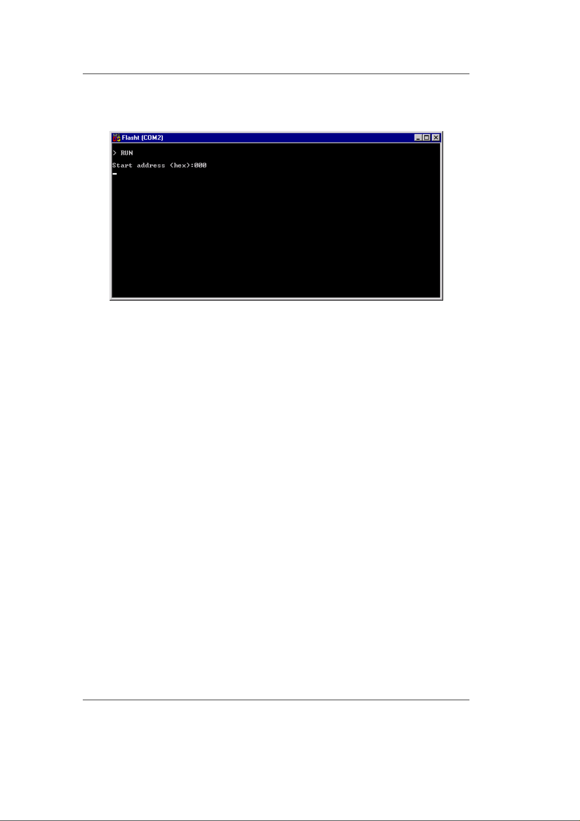
Run from address allows start of execution at a user specified
address:
Erase, Load and Software-Reset results in automatic erasure of
unprotected areas of the Flash, loading of a hexfile and a subsequent
software-reset that executes the contents of the Flash memory.
Return to the main FlashTools menu to run an example program as
described in the next section.
24 PHYTEC Meßtechnik GmbH 2003 L-379e_4

Getting Started
2.3.2.1 “Hello“
The ‘Hello’ example downloads a program to the Flash that, when
executed, initialices the serial port to 9600 baud and sends a character
string from the target hardware back to the host-PC. The character
string can be viewed with a terminal emulation program.
• From the FlashTools main menu enter ‘2’ to choose the Erase
entire Flash-Area command and select ‘Y’ to confirm erasure of
unprotected sectors of Flash memory. You can see the Flash sectors
being erased in the FlashTools window. When all sectors are
erased, the main menu reappears.
• Enter ‘4’ to choose the Load INTEL-hexfile command and press
function key <F2> to specify the input file for download.
• The hexfile has already been installed on your hard disk during the
installation procedure. Enter the correct drive and path to the
nanoMODUL-164 Demo file (default location
C:\PHYBasic\nM164\Demos\Keil\Hello\hello.h86). After pressing
the <Return> key the download starts immediately and you can
watch the process of the download as the code spills across the
FlashTools window as it transmits via the RS-232 connection from
the host to the on-board Flash:
If you have a nanoModul-164 with 1 MB SRAM or 1 MB Flash
use the Demo file at the default location
C:\PHYBasic\nM164\Demos\Keil\Hello\HelloMx\hello.h86).
PHYTEC Meßtechnik GmbH 2003 L-379e_4 25

nanoMODUL-164 QuickStart Instructions
• At the end of the download procedure the main menu reappears and
the downloaded code can be executed.
If the selected Flash bank into which you wish to download code
was not empty (i.e. erased), the following warning dialog box will
appear: “!!! Target address location not empty : xxxx” (where xxxx
is the erroneous address). If this occurs, press the <Space> bar to
return to the main menu (this may take some time) and select the
(2) Erase entire Flash-Area from the main menu to erase all
unprotected sectors of the Flash. Then repeat the download
procedure.
• From within the main menu press function key <F1>. Select ‘Y’ to
exit the FlashTools.
Monitoring the execution of the QuickStart demo requires use of a
terminal program, such as the HyperTerminal program included
within Windows.
• Start the HyperTerminal program within the Windows
Programs|Accessories bar:
26 PHYTEC Meßtechnik GmbH 2003 L-379e_4

Getting Started
• The HyperTerminal main window will now appear:
• Double-click on the HyperTerminal icon ‘Hyperterm’ to create a
new HyperTerminal session.
• The Connection Description window will now appear. Enter
“COM1 Direct” in the “Name” combobox (be sure to specify the
correct COM parameter for your system).
• Next press the Ok button. This creates a new HyperTerminal
session named “COM1 Direct” and advances you to the next
HyperTerminal window.
• The “New Connections Properties” window will now appear.
Specify Direct to COM1 under the Connect Using combobox (be
sure to indicate the correct COM setting for your system).
PHYTEC Meßtechnik GmbH 2003 L-379e_4 27

nanoMODUL-164 QuickStart Instructions
• Select the Configure button in the “New Connections Properties”
window to advance to the next window (COM1 Properties). Then
set the following COM parameters: Bits per second = 9600; Data
bits = 8; Parity = None; Stop Bits = 1; Flow Control = None.
• Selecting OK advances you to the “COM1 Direct –
HyperTerminal” monitoring window. Notice the connection status
report in the bottom lower corner of the window.
28 PHYTEC Meßtechnik GmbH 2003 L-379e_4

Getting Started
• Resetting the Development Board (at S1) will execute the hello.h86
file loaded into the Flash.
• Successful execution will send the character string "Hello World"
from the target hardware to the HyperTerminal window.
• Click the disconnect icon
If no output appears in the HyperTerminal window check the power
supply, the COM parameters and the RS-232 connection.
PHYTEC Meßtechnik GmbH 2003 L-379e_4 29

nanoMODUL-164 QuickStart Instructions
The demo application within the file hello.h86 initializes the serial
port of your nanoMODUL-164 to 9600 baud. The initialization values
are based on the assumption that the microcontroller runs at a 20 MHz
internal clock frequency. Please note that the nanoMODUL-164 is
populated with an oscillator with a frequency of just 5 MHz. An
internal PLL (Phase Locked Loop) device renders an internal 20 MHz
clock frequency. If your nanoMODUL-164 is equipped with an
oscillator with a different frequency value, the demo application
might transmit using another baud rate. This may lead to incoherent
characters appearing in the HyperTerminal window following
execution of code. Additional information can be found in the
readme.txt file in the Hello project directory.
2.3.2.2 “Blinky“
The ‘Blinky’ example sends a program to the Flash that, when
executed, manipulates the single user SMD-LED D1 on the
Development Board that is mounted near the Boot (S2) switch. This
second example program provides a review of the FlashTools
download procedure:
• Ensure that the target hardware is properly connected to the host-
PC and a power supply
• Reset the target hardware and force it into Bootstrap mode by
simultaneously pressing the Reset (S1) and Boot (S2) switches on
the Development Board and then releasing first the Reset (S1) and,
several seconds later, releasing the Boot (S2) switch
• Start FlashTools for DOS from within the PHYTEC Rapid
Development Kit|nanoMODUL-164 program group. For
connection to the target hardware, remember to select the icon
corresponding to the correct serial port on your host-PC
• After the loading process has finished and the main FlashTools
menu appears, enter ‘2’ to choose the Erase entire Flash-Area
command. Select ’Y’ to confirm erasure of unprotected sectors of
Flash memory.
30 PHYTEC Meßtechnik GmbH 2003 L-379e_4

Getting Started
• Once the main menu reappears on the screen, enter ‘4’ to choose
the Load INTEL-hexfile command and press function key <F2> to
specify the blinky.h86 hex input file.
• The ‘Blinky’ hexfile has also already been installed on your hard
disk during the installation procedure. Enter the correct drive and
path to the demo file and press <Enter> (default location
C:\PHYBasic\nM164\Demos\Keil\Blinky\blinky.h86).
If you have a nanoModul-164 with 1 MB SRAM or 1 MB Flash use
the Demo file at the default location
C:\PHYBasic\nM164\Demos\Keil\Blinky\BlinkyMx\BlinkyMx.h86).
• Returning to the main menu, enter ‘5’ to choose the Software-Reset
command. This will render a software-reset to the target system and
start execution of the download program.
• Successful execution of the program will flash the LED with equal
on and off durations.
• Press the function key <F1> to exit FlashTools.
You have now successfully downloaded and executed two preexisting example programs in *.h86-file format.
PHYTEC Meßtechnik GmbH 2003 L-379e_4 31

nanoMODUL-164 QuickStart Instructions
2.3.3 Downloading Example Code with FlashTools for Windows
• Start FlashTools for Windows by double-clicking on the
FlashTools for Windows icon or by selecting FlashTools for
Windows from within the Programs|PHYTEC FlashTools for
Windows program group.
• The Connect tab of the FlashTools for Windows Worksheet
window will now appear.
• Double click on 16-Bit RS232
• Select the correct module from the list and press the Connect
button.
32 PHYTEC Meßtechnik GmbH 2003 L-379e_4

Getting Started
• Select the correct serial port for your host-PC and a 9600
baudrate.
• Click the OK button to load the module based part of the
Flashtools to the target hardware.
The microcontroller tries to automatically adjust to the baud rate
selected within the baud rate tab. However it may occur that the
selected baud rate can not be reached. This results in a connection
error. In this case, try other baud rates to establish a connection.
Before further connection attempts, be sure to reset the target
hardware and render it into Bootstrap mode as described in section
2.2.
PHYTEC Meßtechnik GmbH 2003 L-379e_4 33

nanoMODUL-164 QuickStart Instructions
• After the data transfer you will see FlashTools for Windows
Worksheet window with the following tabs.
Flash Information shows sector and address ranges in FlashMemory:
File Download downloads specified hexfiles to the target hardware:
34 PHYTEC Meßtechnik GmbH 2003 L-379e_4

Getting Started
Protected Areas Information shows protected areas of FlashMemory:
Sector Utilities allow erasure of individual sectors of Flash-Memory:
PHYTEC Meßtechnik GmbH 2003 L-379e_4 35

nanoMODUL-164 QuickStart Instructions
Communication Setup provides you with the possibility to
disconnect the target and reconnect with an equal one. Programming
of several targets is possible for you thereby.
36 PHYTEC Meßtechnik GmbH 2003 L-379e_4

Getting Started
2.3.3.1 “Hello“
The “Hello” example downloads a program to the Flash that, when
executed, performs an automatic baud rate detection and sends a
character string from the target hardware back to the host-PC. The
character string can be viewed with a Terminal Emulation program.
• Choose the Sector Utilities tab, highlight Sector #0 and click on the
Erase Sector(s) button. You can see the Flash sector(s) being
erased at the bottom left hand of the window. When the desired
sectors are erased, the connection properties description returns to
the lower left corner of the window.
• Choose the File Download tab, and click on the File Open…
button.
• The hexfile has already been installed to your hard-drive during the
installation procedure. Type in the correct drive and path to the
nanoMODUL-164 Demo directory (default location
C:\PHYBasic\nM164\Demos\Keil\Hello\hello.h86) and click
Open.
• Click on the Download button. You can watch the status of the
download of the hello.h86 into external Flash-Memory in the
Download window.
PHYTEC Meßtechnik GmbH 2003 L-379e_4 37

nanoMODUL-164 QuickStart Instructions
• At the end of the download, a sector by sector status check of the
Flash-Memory can be viewed in the left-hand corner of the
FlashTools for Windows Worksheet window. Wait until the status
check finishes before returning to work with the board. Once the
status check is complete, the downloaded code can be executed.
If the selected Flash bank into which you wish to download code is
not empty (i.e. erased), a warning dialog box will appear, indicating
“Location not empty! Please erase location and try again.” In this
event, select the Sector Erase tab from the FlashTools for Windows
worksheet, highlight Sector #0 and erase the sector. Then repeat the
download procedure.
• Returning to the Communication Setup tab, click on the Disconnect
button and exit the Flashtools.
Monitoring the execution of the QuickStart demo requires use of a
terminal program, such as the HyperTerminal program included
within Windows.
• Start the HyperTerminal program within the Windows
Programs|Accessories bar.
• The HyperTerminal main window will now appear:
• Double-click on the HyperTerminal icon ‘Hyperterm’ to create a
new HyperTerminal session.
38 PHYTEC Meßtechnik GmbH 2003 L-379e_4

Getting Started
• The Connection Description window will now appear. Enter
“COM1 Direct” in the “Name” combobox (be sure to specify the
correct COM parameter for your system).
• Next press the Ok button. This creates a new HyperTerminal
session named “COM1 Direct” and advances you to the next
HyperTerminal window.
• The “New Connections Properties” window will now appear.
Specify Direct to COM1 under the Connect Using combobox (be
sure to indicate the correct COM setting for your system).
PHYTEC Meßtechnik GmbH 2003 L-379e_4 39

nanoMODUL-164 QuickStart Instructions
• Select the Configure button in the “New Connections Properties”
window to advance to the next window (COM1 Properties). Then
set the following COM parameters: Bits per second = 9600; Data
bits = 8; Parity = None; Stop Bits = 1; Flow Control = None.
• Selecting OK advances you to the “COM1 Direct –
HyperTerminal” monitoring window. Notice the connection status
report in the bottom lower corner of the window.
40 PHYTEC Meßtechnik GmbH 2003 L-379e_4

Getting Started
• Resetting the Development Board (at S1) will execute the hello.h86
file loaded into the Flash.
• Successful execution will send the character string "Hello World"
from the target hardware to the HyperTerminal window.
• Click the disconnect icon
If no output appears in the HyperTerminal window check the power
supply, the COM parameters and the RS-232 connection.
The demo application within the file hello.h86 initializes the serial
port of your nanoMODUL-164 to 9600 baud. The initialization values
are based on the assumption that the microcontroller runs at a 20 MHz
internal clock frequency. Please note that the nanoMODUL-164 is
populated with an oscillator with a frequency of just 5 MHz. An
internal PLL (Phase Locked Loop) device renders an internal 20 MHz
clock frequency. If your nanoMODUL-164 is equipped with an
oscillator with a different frequency value, the demo application
might transmit using another baud rate. This may lead to incoherent
characters appearing in the HyperTerminal window following
execution of code. Additional information can be found in the
readme.txt file in the Hello project directory.
PHYTEC Meßtechnik GmbH 2003 L-379e_4 41

nanoMODUL-164 QuickStart Instructions
2.3.3.2 “Blinky“
The “Blinky” example sends a program to the Flash that, when
executed, manipulates the single user SMD-LED D3 on the
Development Board which is mounted near the Boot (S2) switch.
This second example program provides a review of the FlashTools for
Windows download procedure:
• Ensure that the target hardware is properly connected to the host-
PC and a power supply
• Render the target hardware into Flash Programming Mode by
simultaneously pressing the Reset (S1) and Boot (S2) switches on
the Development Board and then releasing first the Reset (S1) and,
two to three seconds later, release the Boot (S2) switch
• Start FlashTools for Windows
• At the Serial Interface tab of the FlashTools for Windows
Worksheet, specify the proper serial port and transmission speed
for communication between host-PC and target hardware and click
the Load Flashtools button to transfer the modul based part of the
FlashTools for Windows to the target hardware.
• Select the right protocol (default RS232) for further use of the
FlashTools for Windows.
• Returning to the FlashTools for Windows Worksheet, choose the
Sectors Utilities tab, highlight Sector #0 in the Sectors Erase
section of the tab and click on the Erase Sector(s) button to erase
this memory sector
• Wait until the status check in the lower left corner of the
FlashTools for Windows Worksheet finishes, returning the
connection properties description to the lower left corner of the
window
• Next choose the File Download tab and click on the File Open
button
• Type the complete pathway and name of the file you wish to
download C:\PHYBasic\nM164\Demos\Keil\Blinky\blinky.h86
directory (default location)
42 PHYTEC Meßtechnik GmbH 2003 L-379e_4

Getting Started
• Click on the Download button and view the download procedure to
the board in the status window
• Returning to the Communication tab, click on the Disconnect
button
• Press the Reset button (S1) on the Development Board to reset the
target hardware and to start execution of the downloaded software
• Successful execution of the program will flash the LED with equal
on and off durations
You have now successfully downloaded and executed two preexisting example programs in *.h86-file format.
PHYTEC Meßtechnik GmbH 2003 L-379e_4 43

nanoMODUL-164 QuickStart Instructions
44 PHYTEC Meßtechnik GmbH 2003 L-379e_4

3 Getting More Involved
What you will learn with this example:
• how to start the µVision2 tool chain
how to
Getting more Involved
•
Environment)
how to modify the source code from our examples, create a
•
new project and build and download an output *.h86-file to the
target hardware
3.1 Starting the µVision2 Tool Chain
The µVision2 evaluation software development tool chain should
have been installed during the install procedure as described in
section 2.1.
configure the µVision2 IDE (Integrated Development
You can also manually install µVision2 by executing setup.exe from
within the \Software\Keil\Ek166 directory of your PHYTEC
Spectrum CD.
Start the tool chain by selecting µ Vision2 from within the Programs
program group.
After you start µVision2, the window shown below appears. From
this window you can create projects, edit files, configure tools,
assemble, link and start the debugger. Other 3rd party tools such as
emulators can also be started from here.
PHYTEC Meßtechnik GmbH 2003 L-379e_4 45

nanoMODUL-164 QuickStart Instructions
3.2 Creating a New Project and Adding an Existing Source
File
• Open the Project menu and choose New Project. This opens a
standard Windows dialog that asks you for the new project file
name.
• Change to the project directory created by the installation
procedure (default location
C:\PHYBasic\nM164\Demos\Keil\Blinky2).
46 PHYTEC Meßtechnik GmbH 2003 L-379e_4

• In the combobox underneath ‘File name’, enter the file name of the
project you are creating. For this tutorial, enter the name Blinky2
and press Save.
• Now use from the menu Project|Select Device for Target and
double click on Siemens as manufacturer for the CPU. The
nanoMODUL-164 is equipped with a C164 CPU. Choose this
controller type from the list as shown below. This selection sets
necessary tool options for the C164 device and simplifies in this
way the tool configuration
Getting more Involved
• Press the OK button
PHYTEC Meßtechnik GmbH 2003 L-379e_4 47

nanoMODUL-164 QuickStart Instructions
• To give the target of our project a name select the default Target 1
in the project window and click on it. Change the name into
NM164 and press return.
• Select the file group Source Group 1 in the Project Window – Files
page and click on it to change the name into User.
• Click with the right mouse key in the Project Window to open a
local menu. Choose the options Targets, Groups, Files... .
48 PHYTEC Meßtechnik GmbH 2003 L-379e_4

• Select the tab Groups / Add Files and type the new group name
System Files in the Group to Add: section.
Getting more Involved
• Click on Add and then on OK.
• Your project file structure should now look like this:
PHYTEC Meßtechnik GmbH 2003 L-379e_4 49

nanoMODUL-164 QuickStart Instructions
• Now it’s time to add some source code to our project. To do so,
click with the right mouse key on the User group to open a local
menu. The option Add Files to Group ‘User’ opens the standard
files dialog.
• Select the file Blinky2.c.
• Choosing Add adds the Blinky2.c file to your current project
window.
• Close the window.
50 PHYTEC Meßtechnik GmbH 2003 L-379e_4

• Now right click on group System Files and add the File
Start164.a66. (You have to change the Filetype to “ASM source
file *.a ” see this file).
• Your project window should now look like this:
Getting more Involved
At this point you have created a project called blinky2.uv2 and added
an existing C source file called blinky2.c and an existing assembler
file called start164.a66. Next you modify the C source before
building your project. This includes compiling, linking, locating and
creating the hexfile.
PHYTEC Meßtechnik GmbH 2003 L-379e_4 51

nanoMODUL-164 QuickStart Instructions
3.3 Modifying the Source Code
• Double click on blinky2. c to open it in the source code editor.
• Locate the following code section. Modify the section shown below
(the values shown in bold and italic) from the original (150,000)
counts to the indicated values:
while (1) { /* loop forever */
P8_0 = 0; /* output to LED port */
for (i=0; i<
wait (); /* call wait function */
}
P8_0 = 1; /* output to LED port */
for (i=0; i<
wait (); /* call wait function */
}
}
225000
; i++) { /* delay for 150000 counts */
75000
; i++) { /* delay for 150000 counts */
This will change the on/off ratio of the blinky program.
52 PHYTEC Meßtechnik GmbH 2003 L-379e_4

3.4 Saving the Modifications
Getting more Involved
• Save the modified file by choosing File|Save or by clicking the
floppy disk icon .
Note that the icon is active as soon as you modify the file.
3.5 Setting Options for Target
Keil includes a Make utility that can control compiling and linking
source files in several programming languages. Before using the
Make utility, macroassembler, C compiler or linker you must
configure the corresponding options. Most of the options are set by
specifying the device for the project. Only the external memory and
output options must be set.
Enter the changes as indicated below and leave all other options set to
their default values. µVision2 allows you to set various options with
mouse clicks and these are all saved in your project file.
PHYTEC Meßtechnik GmbH 2003 L-379e_4 53

nanoMODUL-164 QuickStart Instructions
To configure the Target:
• Open the Project|Options for Target ‘NM164’ menu and type
the settings for the External Memory as show n below.
Make sure that #1 is set to ROM.
If you have a nanoModul-164 with 1 MB SRAM or 1 MB use the
following settings for the External Memory:
#1 0x0 - 0x3FFF
#2 0x100000 - 0x3FFF
54 PHYTEC Meßtechnik GmbH 2003 L-379e_4

To configure the Output options:
• Select the Output tab and activate the Create HEX-File option.
With this option a INTEL *.HEX file will be created for
download.
Getting more Involved
• Click on OK
PHYTEC Meßtechnik GmbH 2003 L-379e_4 55

nanoMODUL-164 QuickStart Instructions
3.6 Building the Project
You are now ready to run the compiler and linker using the Make
utility.
• Click on the Build Target icon from the µVision2 tool-bar or
press F7.
• If the program specified (blinky2.c) contains any errors, they will
be shown in an error dialog box on the screen.
• If there are no errors, the code is assembled and linked and the ex-
ecutable code is ready to be downloaded to the board. This is
shown in the Output Window, w hich indicates "Blinky2" - 0 Errors
, 0 Warnings. The code to be downloaded to the board w ill be the
name of the project with .h86 as file name extension (in this case
blinky2.h86).
• If a list of errors appears, use the editor to correct them in the
source code and save the file and repeat this section.
56 PHYTEC Meßtechnik GmbH 2003 L-379e_4

3.7 Downloading the Output File
3.7.1 Downloading with FlashTools for DOS
• Exit Keil µVision.
• Reset the target hardware and force it into Flash programming
mode by simultaneously pressing the Reset (S1) and Boot (S2)
switches on the Development Board, releasing first the Reset (S1)
and then the Boot (S2) switch
• Start FlashTools for DOS for your nanoMODUL-164 by selecting
either the FlashTools (COM1) or FlashTools (COM2) icon within
the PHYTEC Rapid Development Kit|nanoMODUL-164 program
group. Which icon to choose depends on the serial port used to
connect to the target system.
Getting more Involved
If you have a nanoModul-164 with 1 MB SRAM or 1 MB Flash
use the icon´s FlashTools Max (COM1) or FlashTools Max
(COM2).
• FlashTools will be loaded to the RAM of the nanoMODUL-164.
The active loading process is indicated by a rotating cursor bar.
PHYTEC Meßtechnik GmbH 2003 L-379e_4 57

nanoMODUL-164 QuickStart Instructions
• After the loading process has finished the main menu appears on
the screen.
• Enter ‘2’ to choose the Erase entire Flash-Area command and
enter ‘Y’ to confirm deletion of all unprotected sectors of Flash
memory. You can see the Flash sectors being erased in the
FlashTool window. When all sectors are erased, the main menu
reappears.
• Enter ‘4’ to choose the Load INTEL-hexfile command and press
function key <F2> to specify the input file.
• The hexfile for download was created during the Make process and
is located in the directory of the Blinky2 project. Enter the correct
drive and path to the Blinky2 hexfile (default location
C:\PHYBasic\nM164\Demos\Keil\Blinky2\blinky2.h86) The
download immediately starts. You can watch the process of the
download in the FlashTools window as code transmits via the RS232 connection from the host-PC to the on-board Flash:
58 PHYTEC Meßtechnik GmbH 2003 L-379e_4

If the selected Flash bank into which you wish to download code
was not empty (i.e. erased), a warning dialog box will appear,
indicating “!!! Target address location not empty : xxxx” where
xxxx is the erroneous address. In this case, press the <Space> bar to
return to the main menu (this may take some time) and select the
(2) Erase entire Flash-Area from the main menu to erase all
unprotected sectors of the Flash memory. Then repeat the download
procedure.
Getting more Involved
• After the download is finished, FlashTools will return to the main
menu automatically.
• Press function key <F1> and select ‘Y’ to confirm that you wish to
exit FlashTools.
• Press the Reset button (S1) on the Development Board
• If the modified hexfile properly downloads and executes, the LED
should now flash in a different mode with different on and off
durations.
You have now modified source code, recompiled the code, created a
modified download hexfile, and successfully executed this modified
code.
PHYTEC Meßtechnik GmbH 2003 L-379e_4 59

nanoMODUL-164 QuickStart Instructions
3.7.2 Downloading with FlashTools for Windows
• Exit Keil µVision2.
• Render the target hardware and force it into Flash programming
mode by simultaneously pressing the Reset (S1) and Boot (S2)
switches on the Development Board, releasing first the Reset (S1)
and then the Boot (S2) switch
• Start FlashTools for Windows
• At the Serial Interface tab of the FlashTools for Windows
Worksheet, specify the proper serial port and transmission speed
for communication between host-PC and target hardware and
click the Load Flashtools button to transfer the modul based part
of the FlashTools for Windows to the target hardware.
• Select the right protocol (default RS232) for further use of the
FlashTools for Windows.
• Returning to the FlashTools for Windows Worksheet, choose the
Sectors Utilities tab, highlight Sector #0 in the Sectors Erase
section of the tab and click on the Erase Sector(s) button to erase
this memory sector
• Wait until the status check in the lower left corner of the
FlashTools for Windows Worksheet finishes, returning the
connection properties description to the lower left corner of the
window
• Next choose the File Download tab and click on the File Open
button
• Type the complete pathway and name of the file you wish to
download
C:\PHYBasic\mM164\Demos\Keil\Blinky2\blinky2.h86
directory (default location)
• Click on the Download button and view the download procedure
to the board in the status window
• Returning to the Communication tab, click on the Disconnect
button
• Press the Reset button (S1) on the Development Board.
60 PHYTEC Meßtechnik GmbH 2003 L-379e_4

• If the modified hexfile properly downloads and executes, the LED
should now flash in a different mode with different on and off
durations.
You have now modified source code, recompiled the code, created a
modified download hexfile, and successfully executed this modified
code.
3.8 “Hello”
A return to the “Hello” program allows a review of how to modify
source code, create and build a new project, and download the
resulting output file from the host-PC to the target hardware. For
detailed commentary on each step, described below in concise form,
refer back to the “Blinky” example starting at section 3.2.
Getting more Involved
3.8.1 Creating a New Project
• Start the Keil µVision2 environment and close all projects that
might be open.
• Open the Project menu and create a new project called hello2.uv2
within the existing project directory
C:\PHYBasic\nM164\Demos\Keil\Hello2
(default location) on your hard drive.
• Add hello2.c and start164.a66 from within the project directory to
the project hello2.uv2.
• Save the project
At this point you have created a project called hello2.uv2 consisting
of a C source file called hello2.c and an assembler file called
start164.a66.
PHYTEC Meßtechnik GmbH 2003 L-379e_4 61

nanoMODUL-164 QuickStart Instructions
3.8.2 Modifying the Example Source
• Double click the file hello2.c from within the project window.
• Use the editor to modify the printf command:
printf ("\x1AHello World\n")
to
printf ("\x1APHYTEC... Stick It In!\n")
• Save the modified file under the same name hello2.c.
• Close the editor window.
3.8.3 Setting Options for Target
• Modify the default options for the Target by defining the following
external memory spaces:
ROM: Start: 0x0 Size: 0x3FFF
RAM: Start: 0x80000 Size: 0x3FFF
If you have a nanoModul-164 with 1 MB SRAM or 1 MB use the
following external memory spaces:
ROM 0x0 - 0x3FFF
RAM 0x100000 - 0x3FFF
• Modify the default options for the output file by selecting the
Create HEX-File checkbox in the Project|Options for
Target....|Output tab. This will automatically create an extended
hexfile for download to the nanoMODUL-164 after compiling.
62 PHYTEC Meßtechnik GmbH 2003 L-379e_4

3.8.4 Building the New Project
• Build the project
• If any source file of the project contains any errors, they will be
shown in an error dialog box on the screen. Use the editor to
correct the error(s) in the source code and save the file and repeat
this section.
• If there are no errors, the code is assembled and linked and the
executable code is ready to be downloaded to the board.
Getting more Involved
PHYTEC Meßtechnik GmbH 2003 L-379e_4 63

nanoMODUL-164 QuickStart Instructions
3.8.5 Downloading the Output File
3.8.5.1 Downloading with FlashTools for DOS
• Exit Keil µVision.
• Reset the target hardware to render it in Flash Programming mode
by simultaneously pressing the Reset (S1) and Boot (S2) switches
on the Development Board and then releasing first the Reset (S1)
and, two or three seconds later, release the Boot (S2) switch
• Start FlashTools for DOS for your nanoMODUL-164 by selecting
either the FlashTools (COM1) or FlashTools (COM2) icon within
the PHYTEC Rapid Development Kit|nanoMODUL-164 program
group. Choose the icon that corresponds to the serial port used on
your host-PC to connect to the target system .
If you have a nanoModul-164 with 1 MB SRAM or 1 MB Flash
use the icon´s FlashTools Max (COM1) or FlashTools Max
(COM2).
• FlashTools will load to the RAM of the nanoMODUL-164. The
active loading process is indicated by a rotating cursor bar.
• After FlashTools has loaded, the main FlashTools menu appears
on the screen.
• Enter ‘2’ to choose the Erase entire Flash-Area command and
enter ‘Y’ to confirm erasure of all unprotected sectors of Flash
memory. You can see the Flash sectors being erased in the
FlashTools window. When the all sectors are erased, the main
FlashTools menu reappears.
• Enter ‘4’ to choose the Load INTEL-hexfile command and press
the function key <F2> to specify the input file.
• The hexfile for download was created during the Make process
and is located in the directory of the Hello2 project. Enter the
correct drive and path to the Hello2 hexfile (default location
C:\PHYBasic\nM164\Demos\Keil\Hello2\Hello2.h86) and press
<Enter>. The download immediately starts. You can watch the
64 PHYTEC Meßtechnik GmbH 2003 L-379e_4

download in the FlashTools window as code transmits via the RS-
232 connection from the host-PC to the on-board Flash.
• At the end of the download the main menu reappears and the
downloaded code can be executed.
If the selected Flash bank into which you wish to download code
was not empty (i.e. erased), a warning dialog box will appear,
indicating “!!! Target address location not empty : xxxx” where
xxxx is the erroneous address. In this case, press the <Space> bar to
return to the main menu (this may take some time) and select the
(2) Erase entire Flash-Area from the main menu to erase all
unprotected sectors of the Flash memory. Then repeat the download
procedure.
• After the download is finished, FlashTools will return to the main
menu automatically
Getting more Involved
• Press function key <F1> and select ‘Y’ to confirm that you wish to
exit FlashTools
PHYTEC Meßtechnik GmbH 2003 L-379e_4 65

nanoMODUL-164 QuickStart Instructions
3.8.5.2 Downloading withFlashTools for Windows
• Exit Keil µVision2.
• Reset the target hardware to render it in Flash Programming mode
by simultaneously pressing the Reset (S1) and Boot (S2) switches
on the Development Board and then releasing first the Reset (S1)
and, two or three seconds later, release the Boot (S2) switch
• Start FlashTools for Windows
• At the Serial Interface tab of the FlashTools for Windows
Worksheet, specify the proper serial port and transmission speed
for communication between host-PC and target hardware and click
the Load Flashtools button to transfer the modul based part of the
FlashTools for Windows to the target hardware.
• Select the right protocol (default RS232) for further use of the
FlashTools for Windows.
• Returning to the FlashTools for Windows Worksheet, choose the
Sectors Utilities tab, highlight Sector #0 in the Sectors Erase
section of the tab and click on the Erase Sector(s) button to erase
this memory sector
• Wait until the status check in the lower left corner of the
FlashTools for Windows Worksheet finishes, returning the
connection properties description to the lower left corner of the
window
• Next choose the File Download tab and click on the File Open
button
• Type the complete pathway and name of the file you wish to
download C:\PHYBasic\nM164\Demos\Keil\Hello2\Hello2.h86
directory (default location)
• Click on the Download button and view the download procedure to
the board in the status window
• Returning to the Communication tab, click on the Disconnect
button
• Exit the FlashTools for Windows.
66 PHYTEC Meßtechnik GmbH 2003 L-379e_4

3.8.6 Starting the Terminal Emulation Program
• Start the HyperTerminal and connect it to the target hardware
using the following COM parameters: Bits per second = 9600;
Data bits = 8; Parity = None; Stop Bits = 1; Flow Control = None
• Resetting the Development Board (at S1) will execute the
hello2.h86 file loaded into the Flash.
• Successful execution will send the modified character string
‘PHYTEC...Stick it in!’ to the Hy perTerminal window.
• Click the Disconnection icon
• Close the HyperTerminal program
You have now modified source code, recompiled the code, created a
modified download hexfile, and successfully executed this modified
code.
Getting more Involved
PHYTEC Meßtechnik GmbH 2003 L-379e_4 67

nanoMODUL-164 QuickStart Instructions
68 PHYTEC Meßtechnik GmbH 2003 L-379e_4

4 Debugging
You can use µ Vision2 Debugger to test the applications you develop
using the C166 compiler and A166 macro assembler. The µVision2
Debugger offers two operating modes that are selected in the
Project|Options for Target|De bug dialog:
• Use Simulator allows to configure the µVision2 Debugger as
software-only product that simulates most features of the 166 /
ST10 microcontroller family without actually having target
hardware. You can test and debug your embedded application
before the hardware is ready. µVision2 simulates a wide variety of
peripherals including the serial port, external I/O, and timers. The
peripheral set is selected when you select a CPU from the device
database for your target.
Debugging
• Use Advance GDI drivers, like Keil Monitor 166 interface. With
the Advanced GDI interface you may connect the environment
directly to emulators, OCDS debugging systems or the Keil
Monitor program.
PHYTEC Meßtechnik GmbH 2003 L-379e_4 69

nanoMODUL-164 QuickStart Instructions
4.1 Loading the Example File
Within the default location C:\PHYBasic\mM164\Demos\Keil\Debug
you will find an already build project called Debug.
• Close all possible open projects and open the project Debug.uv2
with the option Project | open Project.
70 PHYTEC Meßtechnik GmbH 2003 L-379e_4

4.2 Preparing the De bugger
This example utilises the Monitor interface, which automatically
downloads a special Monitor kernel to the target hardware using the
Bootstrap mode. Depending on the Project|Options for Target
‘nM164’|Debug configuration, µVision2 will load the application
program and run the startup code.
• Please select the check-boxes near: Use: Keil Monitor –166 Driver
and Load Aplication at Startup in the Project|Options for Target
‘nM164’|Debug dialog.
Debugging
• Click on the Settings button in the upper right corner of the
Options for Target ´nM164´ window.
PHYTEC Meßtechnik GmbH 2003 L-379e_4 71
nanoMODUL-164 QuickStart Instructions
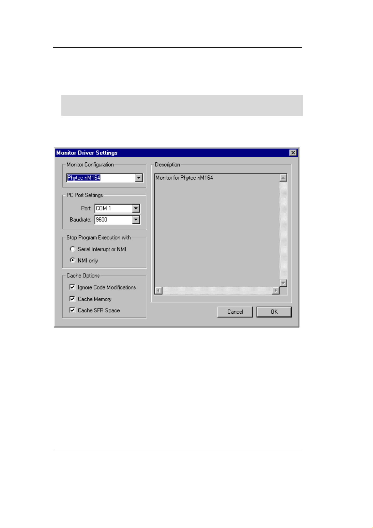
• Select Phytec nM164 from the Monitor Configuration listbox. A
short description for the selected module is shown in the
Description section on the right side.
If you have a nanoModul-164 with 1 MB SRAM or 1 MB select
Phytec nM164 1MB from the Monitor Configuration listbox.
• Select the right COM-Port in the PC Port Settings.
• Click on OK
• Click on OK again.
72 PHYTEC Meßtechnik GmbH 2003 L-379e_4

4.3 Preparing the Target Hardware to communicate with the
Debugger
• Ensure the target hardware is properly connected to the host-PC
and a power supply
• Close Jumper JP3 (see Figure 1 the shaded Jumper in the
Jumperfield)
• Reset the target hardware and render it in Bootstrap mode by
simultaneously pressing the Reset (S1) and Boot (S2) switches on
the Development Board and then releasing first the Reset (S1)
switch and, two or three seconds later, releasing the Boot (S2)
switch.
Since the required microcontroller portion to communicate with the
Keil Monitor 166 will be automatically downloaded using the
Bootstrap mode there is no further preparation of the target system.
Debugging
4.4 Starting the Debugger
• To start the µVision2 debug environment, click on the debugger
icon
from left to right at the button of your screen which indicates the
download process of the Monitor- and Debug-Program.
• If a problem occurs during the data transfer you will see the
following window:
• You could now restart your nM164 as described in section 4.3 and
press Try Again or choose Settings.. and make sure, that the right
COM-port is selected.
on the µVision2 toolbar. You will see a blue bar growing
PHYTEC Meßtechnik GmbH 2003 L-379e_4 73

nanoMODUL-164 QuickStart Instructions
• If the data transfer was successful choose View|Dissassembly
Window and you will get a screen similar to this shown below.
The project window changed to the register value view and the
debug toolbar is shown. The lower right screen shows the Watch
& Call Stack Window. (If you can’t see one of these enable it in
the View menu).
• You will see the source code on your screen in the Disassembly
Window. Note that you will not see your C source code because the
program starts at 00000H – which is the reset vector - with some
assembler instructions. There is an assembler jump to a section of
initialization code which then branches to your C main program. In
this example you will see the JMPS instruction at 0000H and some
parts of the C code.
• Click once on StepInto! . You will see the assembly code of
the initialization routine. DISWDT (disable watchdog) is the first
instruction. EINIT (E8H) signals the end of the initialization
routine of the CPU.
74 PHYTEC Meßtechnik GmbH 2003 L-379e_4

• To view the Output window, if not already visible, select
View|Output window.
• At the Output window prompt, type in g,main and press
Enter (notice the comma !) to run the CPU to the start of the ‘main’
function. The program counter will advance to ‘main’. Note you
can press the up arrow key to get the history of keys typed in the
Output Window.
• You can single step using the StepInto icon. You are now
ready to use the debugger window to step through code, set
breakpoints, and issue the Go command to start program execution.
You can examine special function registers, memory locations, and
register values, etc.
4.5 Using the Keil µVision2 Debug Features
4.5.1 Breakpoints
Debugging
• Click on a memory location such as line number 42 first.x++. A
colored bar appears marking this position.
• You can click on Run to Curser line to reach this point
or you can double-click and set a breakpoint. Set a breakpoint
here with the double-click. The red mark on the left-hand of
the selected line indicates the breakpoint.
• Click on RUN and the program will run and stop at the
breakpoint.
• Double click on the breakpoint to remove it.
4.5.2 In Line Assembler
• Open the Watch & Call Stack Windows with a click on this
icon: You could see the actual values of the variable
bigcount in the Watch window.
• Double click in line 48 to set a breakpoint.
• Click on RUN a few times. This will continue the endless loop
until program execution stops at the breakpoint. See how the
value of bigcount changes with each RUN.
PHYTEC Meßtechnik GmbH 2003 L-379e_4 75

nanoMODUL-164 QuickStart Instructions
• Open the Inline Assembler window by selecting Debug|Inline
Assembly...
• Move the Window with your mouse to your upper left hand so
you can see your source code and the Watch Window.
• Type the address 0x64 in the Current Assembly Address field
and press Enter on your keyboard. The assembly code at this
address appears in the Current Instruction field. It is the
addition of the variable bigcount with 2.
• Type the assembler instruction ADD R10,#3 in the Enter New
Instruction field and press Enter. You could see the change of
your source code at address 0x64H.
• Close the Inline Assembler window.
• Click on RUN a few times and see that the value of bigcount
now is added with 3 at each run.
• Remove the breakpoint at line 48 with a double mouse click.
4.6 Single Stepping
• The debugger uses “Step Into” to single step one instruction at
a time. “Step Into” is also used to enter a function in the same
fashion.
• “Step Over” means to skip over a function that you are
not interested in.
• “Step Out” is used to exit a function you are currently in.
“Step Out” is very useful if you find yourself in a function you
are not interested in and need to return quickly to your intended
function.
• If the debugger gets stuck, execute a reset using the RESET
icon located next to the RUN icon. To isolate any
problems from the target hardware board you could use the
software simulator instead of the Monitor. You can also use the
hardware reset button on the board.
• With the cursor on line 42 click on StepInto until you enter the
function stepout(). Note that you must click on StepInto 10
times to exit the for loop within the function stepout().
76 PHYTEC Meßtechnik GmbH 2003 L-379e_4

• Repeat the process using StepOver and you will not enter the
function although it will be executed. Use the command $=\42
within the Output Window to reposition the program counter to
line 42 prior to further code execution. This command takes a
line number preceded by a backslash to set the program
counter. The StepOver feature is useful to skip function calls
you are not interested in debugging.
Note that the StepOut button is grayed out and not available in
Monitor mode. StepOut is available in the simulator and provides a
quick escape from a function by executing the next return
instruction.
• As you step through the program - the appropriate values in the
Regs window will change colour as their values are updated. Most
of the variables have been allocated to fast internal CPU registers
by the µVision2 compiler.
Debugging
4.6.1 Memory Window
• If the Memory Window is not already visible, activate it by
selecting View|Memory window from the µVision2 tool bar.
• Type 0x5000 at the Address: field and press enter. The addresses
displayed in the Memory Window should change starting at this
address. This is the memory area for the variables of the project.
• Set a breakpoint at line 47 (count++). Note that as you press Ru n,
the contents of the memory changes as the structure values are
incremented at lines 42 through 45. Remove the breakpoint at line
47 with a double mouse click.
• Close the Memory W indow.
PHYTEC Meßtechnik GmbH 2003 L-379e_4 77

nanoMODUL-164 QuickStart Instructions
4.6.2 Watch Window
• If not already visible view the Watch Window by selecting
View|Watch & Call Stack window at the µVision2 menu.
• The Watch Window displays memory contents as specified by
name. Structures can also be displayed.
• Click on the Files tab in the Project window and double click
on the Debug.c filename to open it. Scroll down till you could
see the yellow program counter arrow .
• Click on the Watch #1 tab at the bottom of the Watch Window
• To add variable symbols just click with the right mouse button
on the symbol name in you source code and choose Add “...”
to Watch Window. Add the variables bigcount and first to
WatchWindow #1. Till first is a structure with the members x
and y the Watch Window shows a + symbol left from first.
Click on + to see the structure members x and y.
78 PHYTEC Meßtechnik GmbH 2003 L-379e_4

• Click in line 42 of the C source code (the line-counter is
displayed at the bottom of the µVision2 window) and choose
Run to Cursor line from the Debug Toolbar.
• Now choose Step into few times and look how the variable
values are changing in the Watch Window.
4.7 Resetting Simulator and the nanoMODUL-164
• Debugger in Simulator mode: When you are using the simulator
(i.e. no connection to target hardware), pressing the Reset CPU
icon does not cause a running simulation to stop at the current
point of execution. Reset CPU starts the application from the
beginning address (0) again. Press the Halt button to halt a
program under normal conditions.
• Debugger in Monitor mode: The Monitor runs in the target
hardware. A Debugger reset sets the IPC to zero and performs other
initialization routines if no user application was started. It is not as
complete as a hardware-reset (pressing S1 on the Development
Board). The best method of stopping a running application is to
press the Halt button rather than the Reset CPU in Monitor mode.
Halt tries to stop a running application when the ’Serial interrupt
or NMI’ option is enabled. If this option is not enabled, a dialog
box is displayed in which you can select the next step. This has the
advantage of detecting any ‘infinite loop‘ in which your program
might be stuck. With reset, you start again at address 0.
Debugging
• The PHYTEC Development Board does not have a hardware NMI
button. A NMI is the most reliable way to stop a running program.
This is even more important when you are using the Bootstrap
version of the Monitor because it is difficult to re-synchronize the
Debugger and the kernel. For example, it is not possible for the
Debugger to re-synchronize automatically by pressing the
hardware-reset button (S1) if the monitor has been downloaded
with the Bootstrap Loader. It must be restarted manually by
restarting the Debugger.
PHYTEC Meßtechnik GmbH 2003 L-379e_4 79

nanoMODUL-164 QuickStart Instructions
80 PHYTEC Meßtechnik GmbH 2003 L-379e_4

5 Advanced User Information
This section provides advanced information for successful operation
of the nanoMODUL-164 with the Keil tool chain.
5.1 FlashTools
5.1.1 FlashTools for DOS
Flash is a highly functional means of storing non-volatile data. One of
its advantages is the possibility of on-board programming.
Programming tools for the Flash device are delivered with the
nanoMODUL-164 in the form a set of executable and binary files to
run under DOS. This tools make use of the Bootstrap mode to transfer
executable code to the nanoMODUL-164 that, in turn, download user
code into the Flash. Additionally, the re-programmable Flash device
on the nanoMODUL-164 enables easy update of user code and the
target application in which the nanoMODULl-164 has been
implemented.
Advanced User Information
Currently the nanoMODUL-164 can be populat with three different
sized Flash devices: a 29F200 with 256 KB, a 29F400 with 512 KB or
a 29F800 with 1 MB.
FlashTools always uses the Bootstrap mode to transfer the required
microcontroller firmware to the nanoMODUL-164. Hence, there is no
restriction in using the Flash memory for storing user code.
Before Flash programming FlashTools will adjust the internal Chip
Select Unit and the bus configuration of the microcontroller during
the Bootstrap download. This results in the following programming
memory model:
♦ Flash addressable at 00:0000H-07:FFFFH
(up to 512 KB Flash)
♦ RAM addressable at 08:00000H-0F:FFFFH
(up to 512 MB RAM)
PHYTEC Meßtechnik GmbH 2003 L-379e_4 81

nanoMODUL-164 QuickStart Instructions
If you have a nanoModul-164 with 1 MB SRAM or 1 MB Flash the
memory model is different:
RAM from 0x000000 to 0x0FFFFF,
ROM from 0x1000000 to 0x1F7FFF).
Using the Bootstrap mode to transfer the required microcontroller
firmware to the nanoMODUL-164 the FlashTools maintains its
independent Flash programming capability.
5.1.2 FlashTools for Windows
Flash is a highly functional means of storing non-volatile data. One of
its advantages is the possibility of on-board programming.
Programming tools for the Flash device are delivered with the
nanoMODUL-164 in the form a set of executable and binary files that
run under Windows9x/NT. These tools make use of the Bootstrap
mode to transfer executable code to the nanoMODUL-164 that, in
turn, download user code into the Flash. Additionally, the reprogrammable Flash device on the nanoMODUL-164 enables easy
update of user code and the target application in which the
nanoMODUL-164 has been implemented.
Currently the nanoMODUL-164 can be populat with three different
sized Flash devices: a 29F200 with 256 kByte, a 29F400 with 512
kByte or a 29F800 with 1 MB.
FlashTools always uses the Bootstrap mode to transfer the required
microcontroller firmware to the nanoMODUL-164. Hence, there is no
restriction in using the Flash-Memory for storing user code.
Before Flash programming FlashTools will adjust the internal Chip
Select Unit and the bus configuration of the microcontroller during
the Bootstrap download. This results in the following programming
Memory-Model:
♦ Flash addressable at 00:0000H-07:FFFFH
(up to 512 kByte Flash)
♦ RAM addressable at 08:00000H-0F:FFFFH
(up to 512 MB RAM)
82 PHYTEC Meßtechnik GmbH 2003 L-379e_4

If you have a nanoModul-164 with 1 MB SRAM or 1 MB Flash the
Memory-Model is different:
RAM from 0x000000 to 0x0FFFFF,
ROM from 0x1000000 to 0x1F7FFF).
Using the Bootstrap mode to transfer the required microcontroller
firmware to the nanoMODUL-164 the FlashTools maintains its
independent Flash programming capability.
5.2 Start164.a66
The code within the assembly file start164.a66 is responsible for the
initial controller configuration and the start-up initialisation of your C
project. This includes adjusting the properties of the external bus
signals and Chip Select signals, setting of the system stack,
initialisation of variables and clearing of memory areas.
It is very important that this code will execute prior to the execution
of user code. To ensure this, it is recommended that the startup code
occupy the Reset vector of the application, which is the location the
microcontroller starts execution after Reset (0x0000). After
performing the initialisation steps your individual main() function is
called by the start-up code. To accommodate the start-up code to the
needs of your application copy it from the directory described above
to your project directory. You can then edit, modify and compile it
using the Keil macroassembler. Since the start-up code will usually
be implicitly taken into consideration from the default runtime
libraries you must now explicitly tell your linker to instead consider
your individual startup object file. To do this we recommend adding
your modified start164.a66 file to your project. Be sure that it is
always included in the Link/Lib process of your project (see options
within the Project window of the Keil tool chain in section 3.5).
Advanced User Information
PHYTEC Meßtechnik GmbH 2003 L-379e_4 83

nanoMODUL-164 QuickStart Instructions
The Keil tool chain collects all initialization information for preinitialized variables (e.g. int i=3;) during compile and link time. This
information is stored within a special segment in the form of a list of
binary data entries. To mark the end of this list, the tool chain adds a
special entry to the list. Whenever the startup code finds this special
entry it ends the initialization of variables and continues executing.
Note that this end of list entry comes from the start164.obj object file.
To ensure consideration of all of your pre-initialized variables, you
must move start164.obj to the end of the list of your link files.
Otherwise some of your pre-initialized variables may not be
initialized by the startup code during runtime. It is usually very
difficult to detect such a mistake.
We recommend to always move start164.a66 to the end of your
projects file list.
5.3 Linking and Locating
The Linker has to combine several re-locatable object modules
contained in object files and/or libraries to generate a single absolute
object.
In addition the Linker must locate several segments of type code,
constants and data to fixated address locations within the address
range of the microcontroller to ensure the natural or explicitly
declared properties of these segments.
Data segments must always be located to any kind of random access
memory (e.g. RAM), code and constants segments should be located
to any kind of non-volatile memory (e.g. Flash). The C166 family has
a Von-Neumann architecture which uses the same read signal to fetch
data and also code or constants. To distinguish between non-volatile
and modifiable memory physically different memory devices must be
addressable within different address ranges.
84 PHYTEC Meßtechnik GmbH 2003 L-379e_4

To enable easy accommodation of the linking process the Linker
collects segments of equal type to classes.
The Keil tool chain distinguishes the following classes:
• xCODE: code for several addressing modes (x = N, I, F, H or X)
• xDATA: not initialised data for several addressing modes (x =
N, I, F, H or X)
• xDATA0: pre-initialised data for several addressing modes (x =
N, I, F, H or X)
• xCONST: constants for several addressing modes (x = N, I, F, H
or X)
It is required that all xDATA and xDATA0 classes segments are
located to any internal RAM of the C164 or any external RAM of the
nanoMODUL-164. Also all xCODE and xCONST classes must be
located to any internal non-volatile memory (e.g. Flash, OTPROM) of
the C164 or any external Flash-Memory of the nanoMODUL-164.
Advanced User Information
A near address data area (NDATA, NDATA0) must reside in one data
page (16 kByte). A near address code area (NCODE, NCONST) must
reside in one code segment (64 kByte).
To ensure proper execution of your application you must take into
account the runtime Memory-Model when linking and locating. This
means that you must instruct the Linker where to assume external
RAM for locating data classes and Flash for locating code and
constant classes.
The default configuration of the nanoMODUL-164 has 256 kByte
Flash and 256 kByte RAM.
Note, that you will see multiple mirrors of a memory device that has a
physical smaller address range than the associated address range of
the Chip Select signal.
PHYTEC Meßtechnik GmbH 2003 L-379e_4 85

nanoMODUL-164 QuickStart Instructions
For instance if you adjust Chip Select Signal /CS1 to be active within
an address range of 1 MB and the actually memory size populating
the nanoMODUL is just 256 kByte, you will get three mirrors of your
RAM.
5.4 Debugging using Monitor kerne l
Whenever you decide to use the µVision2 target debugger or Mon166
target Monitor to debug your application, some special precautions
must be taken into consideration to ensure proper code execution of
your application.
Your application and the Keil Monitor kernel contained in the files
boot and monitor must share some memory locations within the target
system. If you do not consider the physical Memory-Model already
claimed by the kernel and the memory requirements of the kernel, you
may get conflicts in memory use. This typically leads to variables
containing not their assigned value, functions returning bad results
and modified code.
If you have a nanoModul-164 with 1 MB SRAM or 1 MB Flash use
the files from the default location:
C:\PHYBasic\nM164\Tools\Mon\MonMx
To obtain information about the memory requirements of the Monitor,
the corresponding memory map file monitor.m66 is made available
together with the monitor executable file. This file contains a detailed
memory map of the Monitor and is also located in the default
destination mentioned above.
You have to link your application to prevent any overlapping memory
ranges. Since the Monitor also uses some special interrupts for
communication with the host-PC at runtime, you should add a
Reserve: statement for 0x008-0x011, 0x0AC-0x0AF to the Location
tab of your L166 Linker options to reserve at least these ranges.
86 PHYTEC Meßtechnik GmbH 2003 L-379e_4

You should always ensure segments of your application will not reach
the segments of the Monitor. The Monitor’s segments will usually be
linked to the top of the memory leaving you as much memory space
as possible.
The Monitor is linked under the assumption of maximum memory
upgrading for Flash bank 1 and RAM bank 1. Remember that you will
have multiple additional mirrors of the physical devices actually
mounted on the nanoMODUL-164 if their capacity is less than the
maximum value of 1 MB.
For instance if you have 256 kByte of RAM mounted on the
nanoMODUL-164 you will have one additional mirror of the RAM
within the reserved 512 kByte range. Note that in this case all
associated address ranges of 0x40000-0x7FFFF will actually address
the same physical device address range of 0x00000-0x3FFFF. This
really means that exactly the same physical memory location can be
addressed using four different internal addresses. This must be taken
into consideration when you verifying your memory mappings.
Advanced User Information
PHYTEC Meßtechnik GmbH 2003 L-379e_4 87

nanoMODUL-164 QuickStart Instructions
88 PHYTEC Meßtechnik GmbH 2003 L-379e_4

Appendices
A Troubleshooting
A.I µVision2 debugger in Monitor mode:
If µVision2 communication to the target system is not successful, it
will error out as indicated in the dialog box shown below. If this
happens, check if the proper serial port is selected or try other baud
rates. The correct speed should be 9,600 baud. Click on Try Again
after forcing the target system into Bootstrap mode again and
reentering communication parameters.
Appendices
The serial FIFO buffer in Windows 95 can cause transmission
problems. µVison2 debugger may have problems completing the
communication initialization process. This can be intermittent. The
FIFO can be disabled under Controlpanel|System|Device
Manager|Port Settings|Advanced. Make sure Use FIFO buffers in this
menu is not activated.
PHYTEC Meßtechnik GmbH 2003 L-379e_4 89

nanoMODUL-164 QuickStart Instructions
A.II Monitor Configuration Error
If Monitor 166 kernel download is not successful, it will error out as
indicated in the “MONITOR Configuration Error” dialog box shown
below. If this happens, make sure that you have selected the right
target hardware under Options for Target|Debug|Settings|Monitor
configuration. This step is crucial to ensure proper communication
between the target hardware and debug environment.
90 PHYTEC Meßtechnik GmbH 2003 L-379e_4

Document: nanoMODUL-164 QuickStart Instructions
Document number: L-379e_4, May 2003
How would you improve this manual?
Did you find any mistakes in this manual? page
Suggestions for Improvement
Submitted by:
Customer number:
Name:
Company:
Address:
Return to:
PHYTEC Technologie Holding AG
Postfach 100403
D-55135 Mainz, Germany
Fax : +49 (6131) 9221-33
PHYTEC Meßtechnik GmbH 2003 L-379e_4

Published by
PHYTEC Meßtechnik GmbH 2003 Ordering No. L-379e_4
Printed in Germany
 Loading...