

Page 1

OPERATING MANUAL
TS - 4
Thermal Microscope Stage
CONTENTS
Section Page
1.0 GENERAL DESCRIPTION 2
2.0 SETTING UP THE THERMAL 3
MICROSCOPE STAGE
3.0 OPERATING INSTRUCTIONS 6
4.0 SPECIFICATIONS 7
5.0 MAINTENANCE, WARRANTY 8
AND SERVICE
EB TS4 1198
Page 2
TS-4 THERMAL MICROSCOPE STAGE
1.0 GENERAL DESCRIPTION
The TS-4 Thermal Microscope Stage consists of:
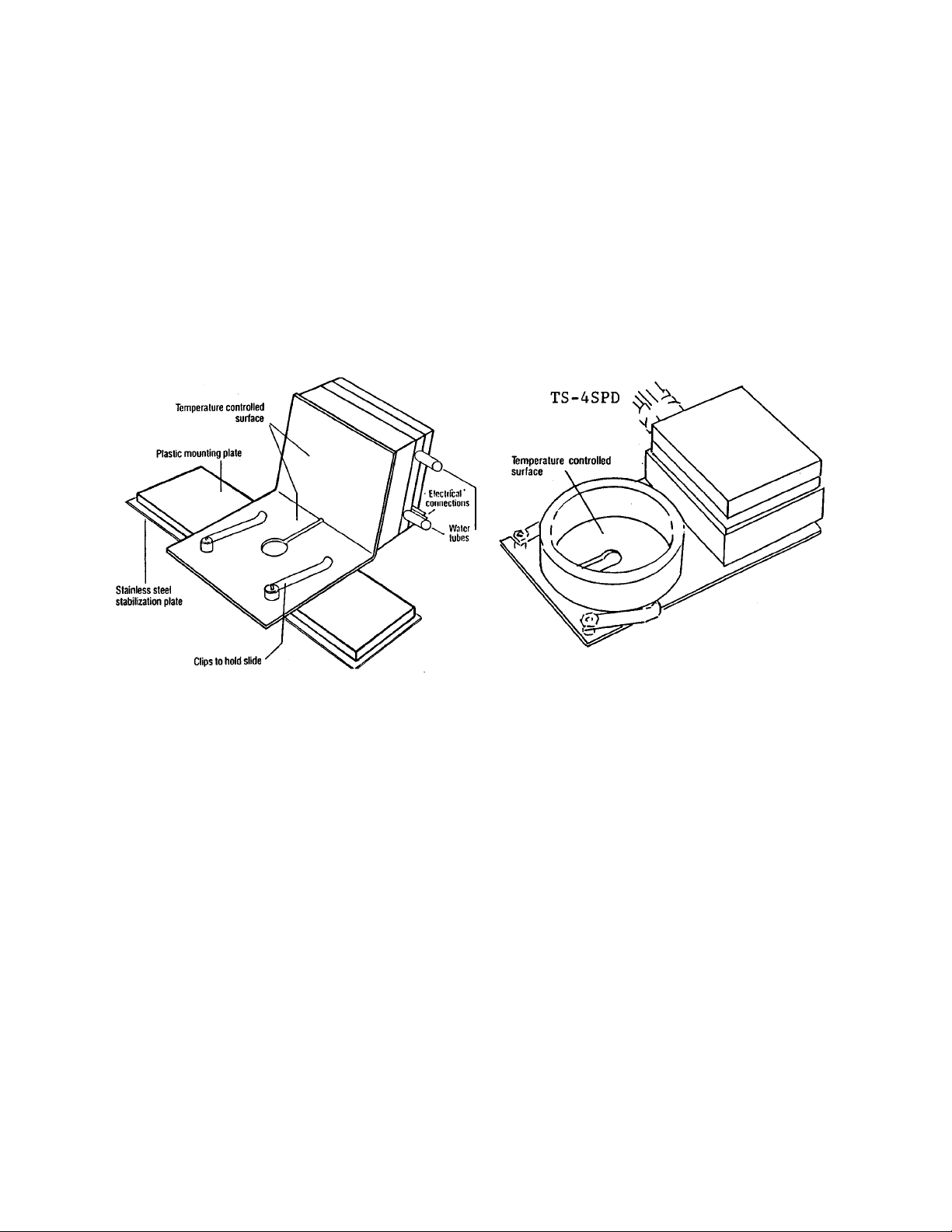
1.1 The STAGE, which is available in several configurations or may be custom designed.
Heat is supplied to or withdrawn from the specimen by means of a thermoelectric heat pump
attached to the upright portion of the controlled plate, Excess heat is conducted away by the cooling water. When the stage is operated below room temperature, a curtain of cold air flows over the
specimen, minimizing condensation and improving temperature conformity.
1.2 The CONTROLLER will maintain stage temperature at any point within the stated range of
the stage, as follows:
TS-4 -20
o
to +60oC
TS-4ER -20
o
to +100oC
TS-4SPD -10
o
to +60oC
TS-4LPD -10
o
to +60oC
1.3 The DIGITAL THERMOMETER and TEMPERATURE PROBE.
A thermocouple microprobe is included with the equipment. If this probe is connected to the external probe input, the controller can be used as an independent thermometer. Range is -100
o
to
+200oC and resolution is 1/10o.
1.4 OPTIONAL PUMP AND TANK UNIT
The Thermal Microscope Stage needs running water for operation. If access to a water tap is inconvenient, a circulating pump with a 5 gallon tank is required. Our pump and tank unit, model PTU-3
can be used for this purpose.
2
Page 3
2.0 SETTING UP THE THERMAL MICROSCOPE STAGE
Sections 2.1 to 2.5 describe setup of the TS-4 with a Pump and Tank Unit, PTU-3. If you are
using running water from a tap, please see section 2.8.
2.1 WATER PUMP AND TANK UNIT
Unscrew cap. Fill reservoir with five gallons of distilled water.
AC line cord should be connected to the SWITCHED OUTLET on the rear of the controller.
This ensures that the water is always flowing when the control unit is turned on.
Check water level periodically during operation to ensure that water level is within 3” of the lip
of the container.
Use only distilled water. This avoids discoloration of the tubing due to organic matter in
untreated water. Addition of a purification agent is recommended.
All water connections are automatically self-sealing, to prevent water spills when disconnected.
3
DO NOT OPERATE PUMP UNLESS TANK HAS BEEN FILLED WITH WATER.
PUMP MAY BE DAMAGED IF RUN DRY.
Page 4
2.3 ATTACH AC LINE CORD
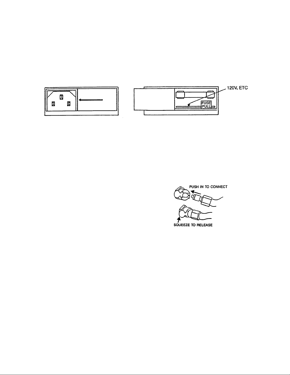
This module is on the back panel, bottom left. There are four settings; 100V for unusually low
power situations, 120V, 220V and 240V. Confirm the selector is set for your requirements.
Slide clear plastic panel to left. If correct voltage is not visible on card, card must be pulled out
and replaced so that correct voltage is visible.
To change the position of the card, eject fuse by pulling on the FUSE PULL lever. Pull card forward, rotate and reinsert.
Replace fuse and slide plastic cover back to the right. Attach line cord to controller.
2.4 ATTACHING WATER TUBES
Pump and Tank Unit is supplied with two water tubes.
All connections are self sealing when disconnected, to
prevent water spills. To connect, push in firmly. Squeeze
to disconnect.
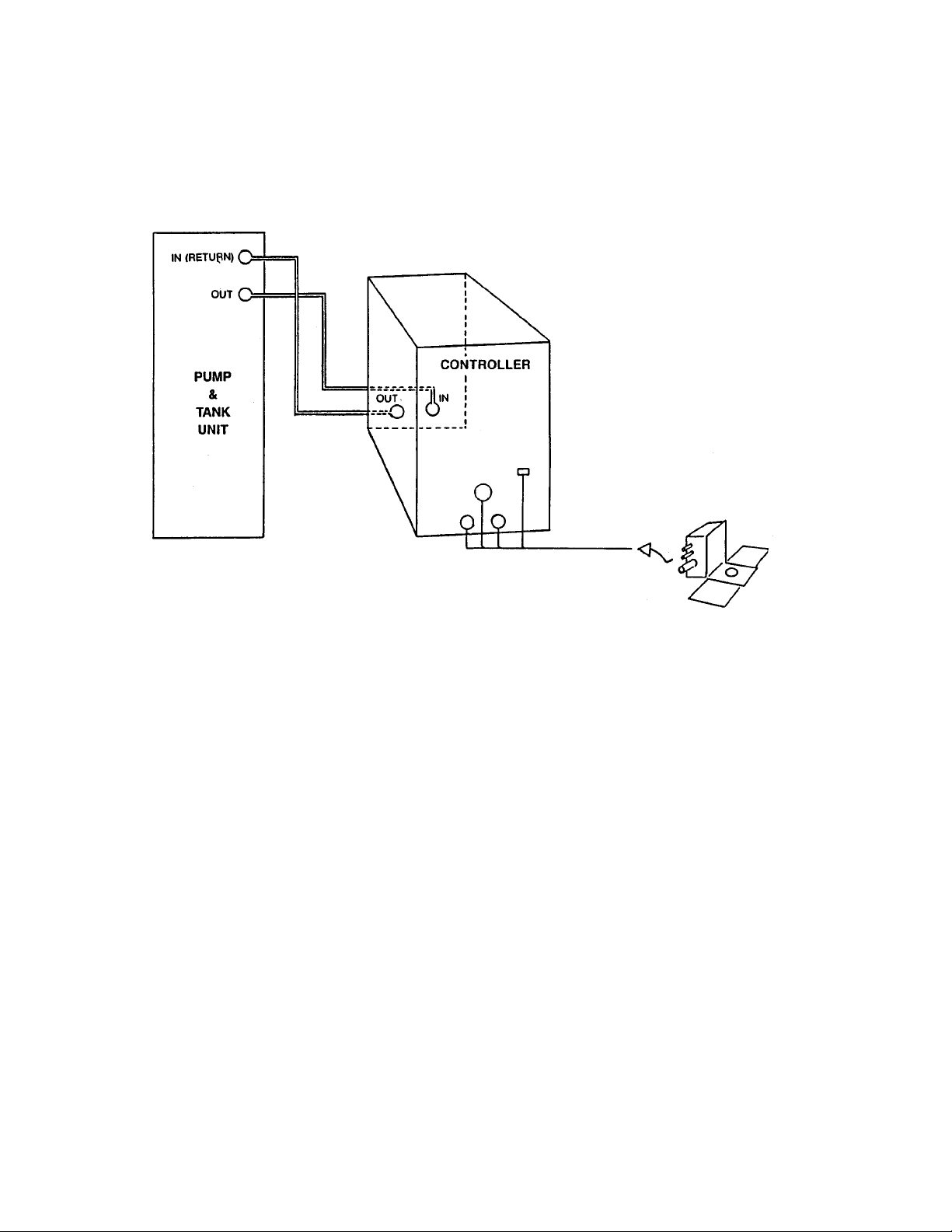
Connect one of the tubes from outlet (OUT) of pump to
water inlet (IN) on rear of controller. Connect the second
tube from inlet (RETURN) of pump to outlet (OUT) on
the rear of the controller.
2.5 CONNECTING THE STAGE
Connect the two water tubes from the stage to the WATER connections on the front panel of the
controller. These tubes are interchangeable - direction of flow is not important.
Connect the black, corrugated cable to the polarized POWER OUTPUT connector on the front
panel. Twist locking nut to lock connector to controller.
Insert blue thermocouple connector into the socket labelled SENSOR B - STAGE.
2.6 FITTING THE STAGE TO YOUR MICROSCOPE
TS-4, TS-4ER
The black plastic base of the TS-4 Stage is the same size as a standard 1" x 3" microscope slide,
and fits into the mechanical stage. The stainless steel base slips under the mechanical stage
clamps, retaining the unit securely.
The upright heat exchanger section is positioned either towards or away from the operator to clear
the movements of the microscope objective turret.
4
BEFORE CONNECTING CONTROLLER TO AC POWER SUPPLY, CHECK THE SETTING
OF THE VOLTAGE REGULATOR MODULE
Page 5

The specimen or slide is placed on the upper surface of the heat transfer plate and held in position
with the stainless steel clips provided. A sensor is mounted on the rear of the stage out of the way
of the slide area. A degree or two of difference between the top of the slide and the stage is normal
and can be allowed for.
The TS-4 stage raises the specimen 0.263” (6.7mm) above the base of the microscope. To achieve
dark field illumination, it may be necessary to adjust the motion stops on the condenser system, or
use a long working distance condenser.
Oil or water immersion objectives are not recommended as the liquid film has a high thermal conductivity. Too much heat is conducted between the specimen and the lens of the microscope, making accurate control impossible.
For inverted microscopes, consideration should be given to the working distance and end diameter
of the objective lens. This will determine the closest approach to the specimen.
FITTING THE TS-4SPD STAGE TO YOUR MICROSCOPE
The stage is comprised of a flat metal plate .080" thick which is heated or cooled by conduction
using an electronic heat pump mounted at one end on the top surface of the plate. The stage rests
on four thin felt pads which sit on the microscope's mechanical platform.
Where necessary, the plate may be secured to the mechanical platform using the spring clips provided with the microscope or any other means. Due consideration must be given to minimizing
thermal contact with the plate. Our engineering staff will assist you with a suitable method of
attachment at the following telephone number:- 973-779-5577.
In addition, please call the above number if any difficulties are encountered in operation of the
mechanical stage such as obstruction of the condenser or interference with the objective lenses.
2.7 CONNECTION TO AC POWER SUPPLY AND "SWITCH ON"
Connect AC line cord from controller to AC outlet and turn controller ON.
A buzzing noise from the water pump indicates that pump is running. Remove the tank cap and
check that water is flowing.
Power indicator lights on the controller and on the pump and tank unit will light.
IF EITHER LAMP FAILS TO LIGHT, SWITCH OFF AND CHECK FUSES.
2.8 CONNECTING RUNNING WATER SUPPLY
If you are not using the Physitemp Pump and Tank Unit, running water must be flowing through
the stage to withdraw heat from the heat exchanger.
Connect the stage to the controller as described in Sections 2.2 through 2.5.
Attach one water tube to the inlet (IN) connection on rear panel of the controller and connect it to a
tap. Attach the other water tube to the outlet (OUT) and arrange tube so that the water flows to
waste. Turn water on. It should flow at 1/2 to 1 liter per minute. If water spurts from the output,
pressure is too high.
BE SURE WATER IS FLOWING SMOOTHLY WHENEVER TS-4 IS IN OPERATION. Stage
may be damaged if water flow is inadequate.
5
Page 6

3.0 OPERATING INSTRUCTIONS
3.1 Check that SENSOR INPUT is switched to B. The digital display will show the temperature
of the stage.
Depress the RUN/SET switch to SET position and hold down while adjusting the SET TEMPERATURE knob. With this 10-turn potentiometer, adjustment may be made to any temperature in the
listed temperature range of the stage (See Section 1.2)
Release the RUN/SET switch and allow the stage to stabilize at set temperature. This should take
1-2 minutes.
If further slight adjustments are needed, use the same procedure.
The controller will now maintain the stage at the set temperature.
3.2 MEASURING TEMPERATURE WITH THE EXTERNAL SENSOR
The digital display of the controller may be use as a readout for the needle microprobe supplied
with TS-4 (or any other type T thermocouple sensor). Range of the thermometer circuitry is -100
o
to +200oC.
Connect the probe to socket marked SENSOR A - EXTERNAL.
Switch SENSOR INPUT to A.
Read temperature on the digital display.
When external sensor is being used, no power is supplied to the stage. After switching SENSOR
INPUT back to B, allow stage temperature to stabilize again.
3.6 WARNING LIGHT
Since the thermocouple modules can be damaged if allowed to overheat, audible and visible warnings of operating failure are provided on the controller.
Fault conditions such as broken thermocouple sensors, lack of cooling water or electronics failure
will trigger safety shutdown and lamp illumination.
6
SWITCH OFF IMMEDIATELY IF WARNING LIGHT COMES ON
OR IF BUZZER ALARM IS HEARD
Page 7

4.0 SPECIFICATIONS
4.1 CONTROLLER
Operating Range: -20
o
to +60oC
Control Accuracy:
+
0.1oC
Digital Readout Resolution: 0.1
o
C
Accuracy: 0.1
o
C, +1 digit
Ambient Operating Range: 15
o
- 45oC
Input Power Requirements: 100 - 120VAC, 60Hz, 100W
200 - 240VAC, 50Hz, 100W
Safety Features: Safety shutdown with warning lamp in case of fault condition
such as sensor breakage, lack of cooling water or electronics
failure.
Size: 8” high x 7” wide x 15” deep
Weight 8 lbs.
Other Features: Spring loaded switch indicates set point
Self-sealing water connectors
Auxiliary AC switched output
4.2 STAGE
Temperature Range: -20
o
to +60oC
Controlled Surface Area: 1 1/4” x 1 1/2”
Weight: 16 ozs., including leads
Material: Copper, nickel plated
Mounting: Plastic. Fits slide holder
4.3 PUMP AND TANK UNIT
Size: 6 1/2” x 15” x 14”
Power Supply: 110V (or 220VAC if ordered)
Power Consumption: 150 Watts
Water Connections: Self Sealing
4.4 THERMOMETER (built into controller)
Temperature Range: -100
o
to +200oC
Resolution: 0.1
o
C
Sensor: Type T Thermocouple, Physitemp type #MT-26/4 or similar
7
Page 8

5.0 MAINTENANCE, WARRANTY AND SERVICE
5.1 MAINTENANCE
The microscope stage needs no maintenance at all. It may be cleaned as necessary with a soft
cloth, water or detergent. DO NOT IMMERSE IN WATER -- because of expansion and contraction due to the wide temperature range, it is not possible to completely seal the stage.
5.2 WARRANTY.
Physitemp Instruments Inc. warrants this system to be free from defects in material or workmanship for 12 months from date of shipment. Repair or replacement will be made at no charge at the
discretion of Physitemp if the defect is not the result of misuse or abuse. Physitemp accepts no
consequential liability for delay in delivery, alleged faulty performance of the product or any other
cause.
Cables and probes are considered expendable and are not covered by this warranty.
5.2 REPAIRS AND RECALIBRATION
For technical or applications information on this instrument call 973- 779-5577.
In the event that any part of this system is to be returned for repair or recalibration, please pack it
with care and send it prepaid to:
Service Department
PHYSITEMP INSTRUMENTS INC.
154 Huron Avenue
Clifton, NJ 07013 USA
Please include with the instrument:
1. A note describing any problems encountered
2. The name and telephone number of a person
we can contact
3. The complete return address for shipping.
For your protection, please pack the item carefully and insure against possible damage or loss.
Physitemp will not be responsible for damage resulting from careless packaging.
Please return freight prepaid.
8
Page 9

9
 Loading...