

Page 1

ASSEMBLY AND OPERATING INSTRUCTIONS
BFS-60MP
CONTROLLER AND THERMOELECTRIC COOLING STAGE
Contents:
1. Contents of Box
2. Unpacking Instructions
3. Installation and Operating Instructions
4. Warranty and Service
PHYSITEMP INSTRUMENTS INC
154 Huron Ave
Clifton NJ 07013
1-800-452-8510
1
Page 2

1. Contents of Box
1. BFS60MP Thermoelectric Cooling Stage
2. Extension Water Tubes (2 - 5 foot long tubes with Male self-sealing
connectors and 2 – 5 foot long tubes with Female self-sealing connectors to
a Y adapter for laboratory tap water supply )
3. BFS-60MP Control Unit
4. 110 VAC 20Amp Power cord
5. Instruction Manual
2. Unpacking Instructions
Remove contents of carton and check all items in the contents list are present.
Visually check that everything is in good condition. If any item appears to be
damaged or is missing please contact Physitemp Customer Service at:
1-800-452-8510
3. Installation and Operating Instructions
Mount the Cooling Stage on to the SM2500 Microtome by clamping the block on
the underside of the stage into the Microtome Specimen Clamp. The wiring and
water tubes may exit from the front or rear of the Microtome. Attach the Male
connectors from the stage water tubes to two female fittings of the extension water
tubing and connect the other end to the laboratory tapwater supply.
Connect the Female connectors from the stage to the two remaining extension
tubes and place the open ends into the waste sink. Gently turn on the cold water
supply until the water is spurting out from the ends of the tubes approximately 3
inches before dropping into the sink when the tubes are held horizontal.
Place the BFS60MP Controller to the side of the Microtome and connect the large
black multi-pin connector on the stage to the mating female connector in the rear
of the controller. The connector is polarized and uses a twistloc ring to secure the
plug to the controller. Twist the ring in a clockwise direction to secure it.
Attach the blue thermocouple plug which breaks out from the wireform to the
mating socket to the right of the black connector labeled ‘feedback sensor’. Ensure
that the fan inlets on the front panel and outlet filters on the rear are not obstructed
during operation. A good airflow is important for the satisfactory operation of the
controller.
2
Page 3
Attach the 110 VAC power cord to the socket on the rear of the controller and to a
20 amp AC outlet socket. Switch the power switch on the AC input module ‘ON’.
The display on the front panel controller will read ‘8.8.8.8’ for several seconds to
ensure that all display segments are operative.
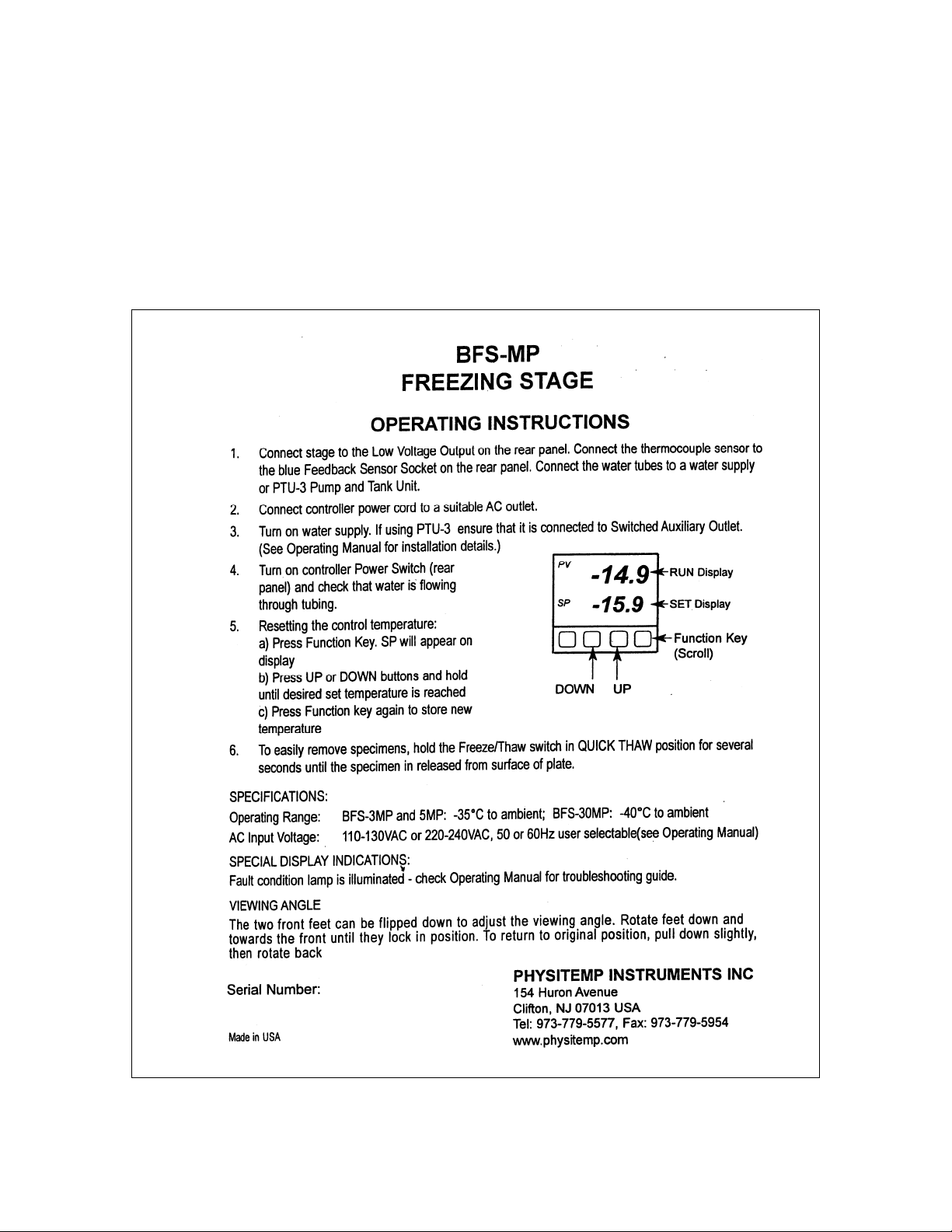
In order to set the stage operating temperature you must follow the instructions
found on top of the controller. These instructions are reproduced below in the
event that those on the controller become defaced.
3
Page 4

Before the surface of the stage freezes apply an ample amount of water/OCT/
sucrose solution to form a base onto which you can freeze your specimen. Once the
specimen has become attached freezing will be facilitated by building a dam of
liquid around the sides of the specimen to reduce heat losses from the specimen to
the surroundings. When the specimen is thoroughly frozen move the microtome
sledge slowly back and forth under the knife to ensure that none of the wiring or
water tubes are interfering with the operation of the microtome.
Quick Thaw feature
In order to quickly remove a frozen specimen from the stage, depress the white
spring loaded on the front panel to the ‘THAW’ position and hold it there until the
surface of the stage melts. Release the switch and quickly remove the specimen
before the surface refreezes. Do not depress the switch longer than is necessary to
remove the specimen as this may cause the stage surface to overheat.
Safety Features
A protection device built into the cooling stage disconnects power to the stage in
the event that the water supply is not turned on or becomes disrupted or when the
plate surface temperature exceeds 60 degrees Centigrade. In the event that either of
these conditions should occur a warning lamp labeled ‘Fault Condition’ will be
illuminated on the front panel. When the condition is rectified the lamp will
extinguish.
In the event of a short circuit in any of the four independent power supplies in the
controller shut off the AC power for 10 seconds and then reconnect. If the problem
persists please contact our engineering department at 1-800-452-8510 between the
hours of 9am-5pm EST.
4
Page 5

4. Warranty and Service
In the event that a system is to be returned for repair, please pack it carefully
and send it prepaid to:
SERVICE DEPARTMENT
PHYSITEMP INSTRUMENTS, INC.
154 HURON AVENUE
CLIFTON, N.J. 07013
Please include with the instrument:
1. A note describing any problems encountered.
2. The name and telephone number of a person we can contact.
3. The complete return address for shipping.
WARRANTY
Physitemp Inc. warrants this instrument to be free from defects in material
and workmanship for 12 months from date of shipment. Repair or
replacement will be made at no charge at the discretion of Physitemp if the
defect is not the result of the misuse or abuse. Physitemp accepts no
consequential liability for delay in delivery, alleged faulty performance of
the product, or any other cases.
For your protection, please pack the item carefully and insure against
possible damage or loss. Physitemp will not be responsible for damages
resulting from careless packaging. Please return freight prepaid.
5
 Loading...