

Page 1

OPERATING MANUAL
BFS-30VT REFRIGERATION MODULE
AND DIGITAL TEMPERATURE CONTROLLER
TABLE OF CONTENTS
1. Summary of Operation
2. Unpacking and Checking Package Contents.
3. Mounting the Refrigeration Module to VT1000 Microtome
4. Connecting the Controller to a Water Supply or the
Closed Loop Water System
5. Operating Instructions
6. Troubleshooting Information
7. Specifications
8. Warranty and Return Information
App.1 PTU-3 Operating Instructions
App.2 ECV-1 Operating Instructions
IMPORTANT
MUST ESTABLISH WATER FLOW
BEFORE TURNING THE UNIT ON
DO NOT IMMERSE THE BATH IN LIQUID OR ICE
1
EB BFS-30VT
Page 2

1. Summary of Operation
The BFS-30VT is designed to provide consistent accurate cooling control to the VT-1000
specimen bath. The BFS-30VT will hold temperature setpoint within ½ degree. The temperature control utilizes a peltier cooling unit. Peltier cooling units are heat exchangers
that generate cooling by removing the heat. In order for a peltier to continue cooling, the
heat must be removed from the cooling unit. Therefore, the BFS-30VT requires an external water source to act as a radiator and remove generated heat. The BFS-30VT is
shipped with fittings and water hoses to accomplish this goal. For those installations
where an external water source in not available or practical, an optional closed loop water
system is available (Our catalog number PTU-3).
The Vibratome BFS-30VT bath mounts inside your current VT-1000 bath. The standard
bath is removed and the new refrigeration chamber mounts to the post in the same manner as the old one. The control unit has a simple set point control LED readout and pushbutton entry control. Once the unit is turned on, the LED displays the set point and current temperature. The set point can be adjusted by simply incrementing the set point up
or down via the pushbuttons.
2. Unpacking and Checking Package Contents
Your BFS-30VT refrigeration module and digital temperature controller is comprised of
the following items:
1. Digital Temperature Controller with AC line cord
2. Refrigeration Bath Module with 3 foot connector lead and water tubing
3. 5 foot water tubing extension with universal tubing adapter and selfsealing female fittings
4. Operating Manual with Warranty Registration Card
Optional accessories purchased with this unit may include:
1. Closed Loop Water System, Catalog # PTU-3 or
2. Electrically Controlled Solenoid Valve, ECV-1
Supplied with the PTU-3 are:
1. An AC line cord with auxiliary input connector
2. Two 5 foot extension water tubes with male and female self sealing fittings
Supplied with the ECV-1 are:
1. An AC line cord with auxiliary input connector
2. A 12 VDC 1.3 Amp desktop power supply
2
Page 3
3. Mounting the Refrigeration Module to yourVT1000 Sectioning System
Remove the black refrigeration bath from its packaging. Remove the cutting head from
the microtome or move it out of the way so that it does not obstruct replacement of the
bath. Dismount the standard bath from the microtome by moving the locking lever at
the front of the bath to the left. Lift the bath straight up to separate it from the mounting
post. Mount the new refrigeration bath in its place and lock into the post by moving the
locking lever at the front of the bath to the right.
4. Connecting the Controller to a water supply or Closed Loop System
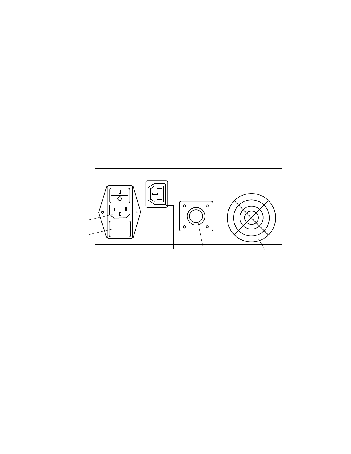
Unpack your BFS-30VT Controller and connect the electrical lead from the refrigeration module to the mating socket on the rear of the controller. Rotate the collar on the
connector housing in a clockwise direction to lock in place.
If you purchased the PTU-3 Closed Loop Water System or the ECV-1 Electrically
Operated Solenoid Valve with your system see the separate instructions below for
installation.
Locate the 5-foot extension water tubes and connect the self-sealing connector female
ends of these tubes to the male connectors on the water tubes from the refrigeration
module. Connect the end of the tube with the universal tubing adapter to your sink
water supply using any suitable water tube with a diameter of up to ½ inch. (A 5/8 inch
adapter is available upon request ). Place the open tubing end from the remaining
tube into the sink or waste drain.
3
AC FUSE
AND
VOLATGE
SELECTOR
COOLING
FAN
OUTPUT TO
REFRIGERATION
MODULE
AUXILIARY
SWITCHED OUTLET
REAR PANEL
CONNECTIONS
POWER
SWITCH
AC SOCKET
Page 4
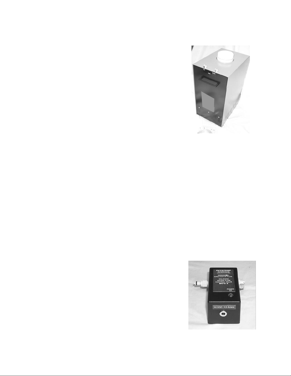
Closed Loop Water System - PTU-3 Installation Instructions
The PTU-3 is supplied with an AC line cord for connection to
the auxiliary outlet on the controller and two 5-foot water
tubes with male and female connectors.
Unpack the pump and tank unit and unscrew the white cap
on top of the tank. Fill the tank to within 3 inches of the top
lip of the neck with distilled water (approx 5 gallons). Add the
sachet of purification agent to the tank. This prevents the
growth of algae inside the tubing and tank. If the tank is ever
emptied and refilled substitute a small quantity of any commercially available dehumidifier treatment in liquid or tablet
form to treat the water.
Connect the AC line cord to the socket on the side of the
tank and to the auxiliary output socket on the rear panel of the controller. This ensures
that the pump is always turned on when the refrigeration module is operative.
Please Note: If the refrigeration module is in use for extended periods of time, the
water temperature will gradually increase. Ice cubes may be added to the tank to
reduce the water temperature.
The tank should be placed no lower than 40 inches below the refrigeration module.
Connect the male ends of the extension water tubes to the mating outlet and return on
top of the tank. Connect the female ends to the tubes from the refrigeration module.
Please note that these connectors are self-sealing to prevent water spills in the event
that they are disconnected while the pump is operating.
ECV-1 Installation instructions
Unpack the ECV-1 Electrically Operated Solenoid Valve. The package includes an AC
line cord and 12VDC desktop power supply. Connect the line cord to the socket on the
power supply and to the rear auxiliary outlet on the
Controller. Connect the power supply 12VDC output to the
input socket on the valve housing. Connect one of the male
fittings from the water tubes from the Refrigeration module
to the female fitting on the valve housing. Connect the
female end of the extension water tube with the universal
tubing adapter at one end to the male fitting on the valve
housing and the other end to your water source. Connect
the remaining water tube directly to the other male water fitting from the refrigeration module and run the other end to
the sink or waste.
4
Page 5

5. Operating instructions
Ensure that the POWER switch on the rear panel of the controller is in the OFF position.
Check the VOLTAGE SELECTOR switch on the rear panel to ensure that it is set for the
correct line voltage.
Connect the AC power cord supplied with the controller to the mating socket on the rear
of the controller and any suitable grounded AC outlet.
Unless you have a PTU-3 or ECV-1, turn on the water supply and adjust the flow rate so
that, with the return water tube held horizontally over the sink, the stream falls approximately 3 inches beyond the end of the tubing.
Turn the POWER switch on the rear of the controller ON and ensure that the display on
the front is illuminated.
If you purchased the ECV-1 and have installed it according to the instructions above,
turn on the water supply now and adjust the flow rate as described in Section 4 above. If
you have a PTU-3 check that the neon lamp on the side of the pump is illuminated and
you can hear a low hum from the pump. Check that water is flowing by observation of
movement of air bubbles inside the tubing or, by removing the cap on the tank, the
stream of water from the return tube which is located at the top of the tank underneath
the tubing connections. (See Appendix 2)
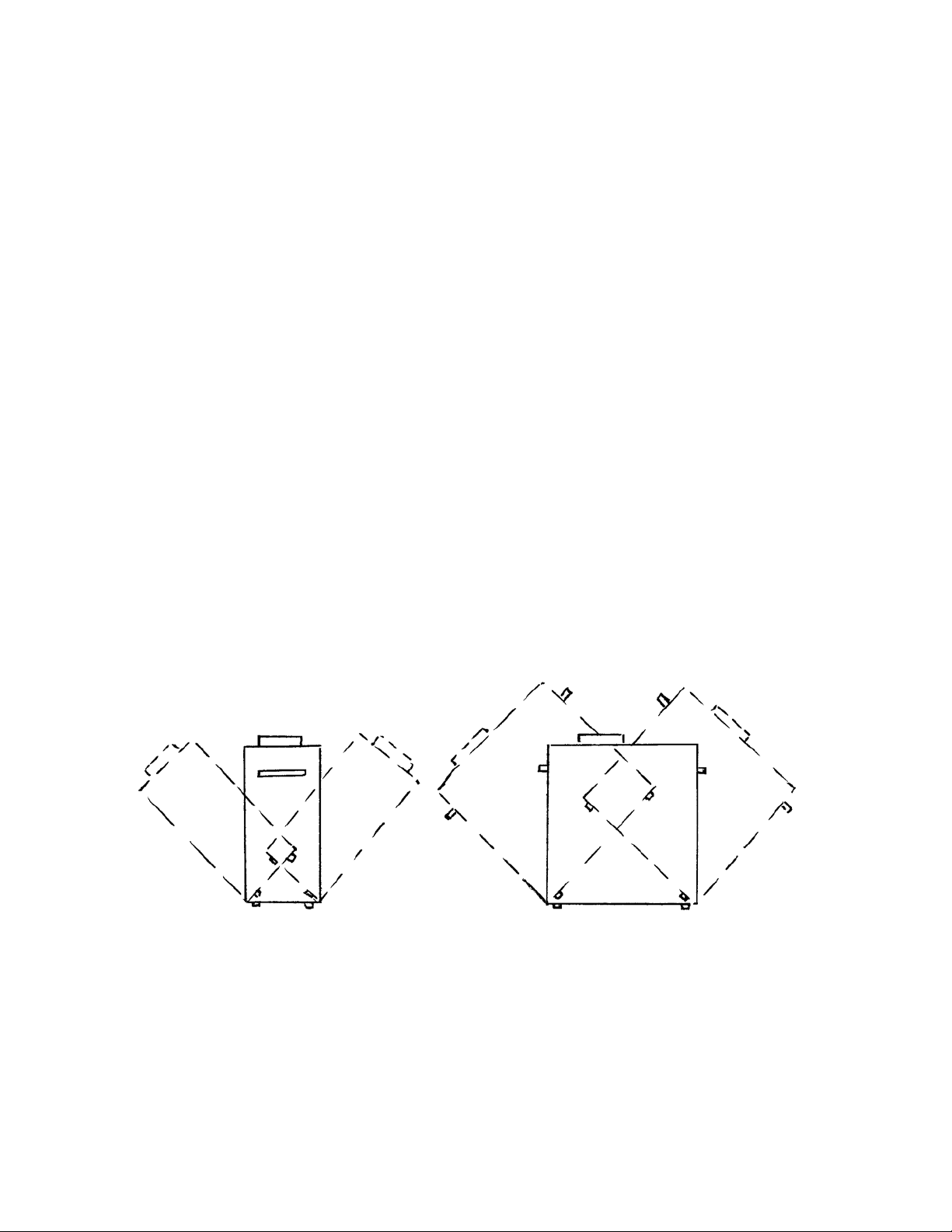
In the event that a loud noise is heard from the pump replace the cap on the water reservoir and tip the pump housing to an angle of approximately 45 degrees in all directions
for about 15 - 20 seconds. Air is sometimes trapped inside the pump when it is initially
filled and this procedure will release it. It may be necessary to repeat this process if the
tank is ever emptied and refilled. (See Appendix 1)
5
Page 6
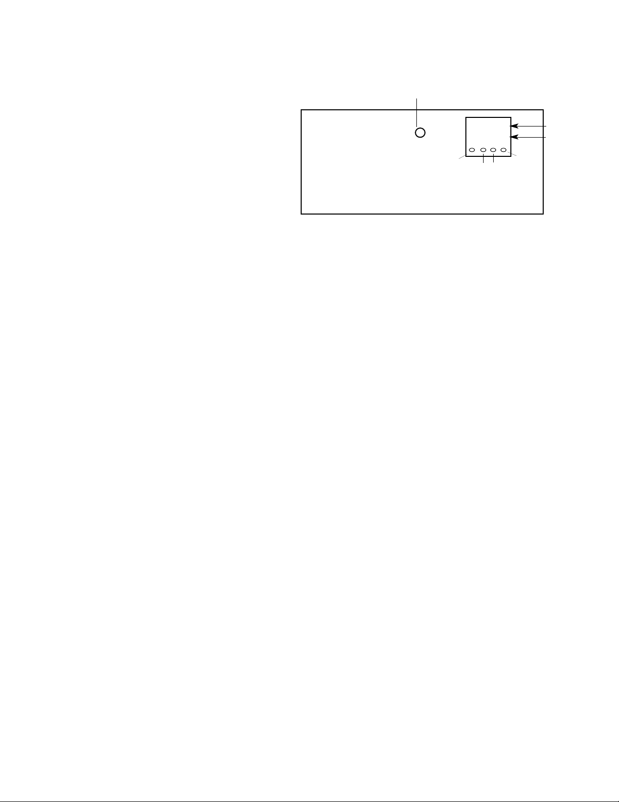
Setting the module operating temperature
4.6 SETTING THE STAGE TEMPERATURE
The operating temperature may be set
anywhere in the range from ambient
down to -35°C (-40°C for BFS-30MP.)
To set control temperature:
a) Press SHIFT. A digit will flash
b) Use UP and DOWN buttons to
change the flashing digit. Press
SHIFT again to select the next
digit.
c) When all digits have been
changed, press SET to enter new
control temperature.
The operating temperature may be set anywhere in the range from ambient down to 10 degrees centigrade. Depress the menu button on the left side of the controller display and hold it down while depressing the down or up buttons in the middle and on
the right of the display to increase or decrease the operating temperature. The set
temperature is displayed in red on the lower half of the display. When the buttons are
released the module will automatically adjust to the new set point. The actual module
temperature is displayed in the upper half of the display in green.
WARNING! Various programmed functions of the display and con-
troller are accessible via the four buttons on the display. It is inad-
visable to make any adjustments to these parameters, which are pre-
set at the factory for optimum performance. In the event that these
operating parameters are changed accidentally please consult our
engineering department for restoration to the original settings.
6
FRONT PANEL CONTROLS
FAULT
CONDITION
UP
SET
SHIFT DOWN
PV -14.9
SV -15.0
RUN display
SET display
Page 7

6. Troubleshooting
1. Controller display fails to illuminate when power is turned on.
Check power cord continuity from the AC outlet to the input socket on the rear of the controller. Check the fuse next to the AC input socket in the rear panel. If these are both OK
try a different AC outlet.
2. Fault Condition lamp is illuminated
As a safety feature, this unit has power supply short circuit protection. In the event that the
output becomes short circuited by a wiring fault, a protection circuit built into the power
supply senses the increase in the current and shuts off the output power. Before output
power can be restored to the controller the AC power supply must be turned off and the
fault condition corrected. Consult our engineering department for further details
If the PTU-3 or ECV-1 is being used, check for adequate water flow as described in
Section 5 above. Touch the silver heat sinks on the underside of the refrigeration bath
cautiously to see if yhey are hot to the touch - this would indicate a low or inadequate flow
rate.
If water flow is OK, the stage or controller may be defective. In order to check the stage,
turn off the power to the controller and remove the stage connection from the rear of the
controller by turning the collar in an anticlockwise direction. An ohmmeter will be required
to make several readings on the stage connector. Once the connector has been removed
the pin numbers are visible as slightly raised numerals on the face of the connector.
Between pins 1 and 2 1 - 3 ohms
3 and 5 100 - 110 ohms
6 and 7 45 - 55 Kilohms
If the readings you obtain do not fall within these ranges please consult our engineering
department for instructions.
3. Controller display is illuminated but module does not cool
Check the setting of the set temperature and adjust if necessary using the instructions
provided in Section 5. If the set temperature is OK check the connector to the module
cable on the rear of the controller and the fault condition light on the front of the controller.
If the fault light is on follow instructions for fault condition number 2.
7
Page 8

7. Specifications
Controller Specifications
Size: 7½ inches W x 10 inches D x 4 ½ inches H
Weight: 5 pounds
Power Requirements: 110-120VAC @ 4 Amps or
220-240 VAC @ 2 Amps Factory set
Grounded Outlet
Operating Range: -10 degrees to Ambient Centigrade
Controller Resolution: 0.1 degrees Centigrade
Display: Dual display of set and run Temp.
In 7mm high led digits
Control Accuracy: + or - 0.2 degrees Centigrade
Power Output to cooling stage: 12 Volts DC @ 10 Amps
Feedback Sensor: 100 ohm Platinum RTD
Safety Features: Power shutoff during overtemperature
condition caused by inadequate coolant flow
(50 degrees C )
Auxiliary AC Outlet: Switched AC Power outlet for PTU-3
or ECV-1
Refrigeration Module Specifications
Size (including bath): 4 3/4” wide x 4 1/2” x 2” thick
Weight: 2. 5 pounds
Temperature Range: Ambient to -10 degrees Centigrade
Cooling Capacity: 120 watts
Nominal operating Voltage: 12 VDC
Nominal operating Current: 10 Amps
8
Page 9

8.0 MAINTENANCE, WARRANTY AND SERVICE
8.1 MAINTENANCE
The stage needs no maintenace at all. It may be cleaned as necessary with a soft
cloth, water or detergent. DO NOT IMMERSE IN WATER
8.2 WARRANTY
Physitemp Instruments Inc. warrants this system to be free from defects in material or
workmanship for 12 months from date of shipment. Repair or replacement will be made
at no charge at the discretion of Physitemp if the defect is not the result of misuse or
abuse. Physitemp accepts no consequential liability for delay in delivery, alleged faulty
performance of the product or any other cause.
Cables and probes are considered expendable and are not covered by this warranty.
8.2 REPAIRS AND RECALIBRATION
For technical applications information on this instrument contact us at:
In the event that any part of this system is to be returned for repair or recalibration,
please pack it with care (in the original packing material if possible) and send it prepaid
to:
Service Department
PHYSITEMP INSTRUMENTS INC
154 Huron Avenue
Clifton, NJ 07013 USA
Please include with the instrument:
1. A note describing any problems encountered
2. The name and telephone number of a person we can contact
3. The complete return address for shipping.
For your protection, please pack the item carefully and insure against possible damage
or loss. Physitemp will not be responsible for damage resulting from careless packaging. Please return freight prepaid.
9
Page 10
APPENDIX 1
OPERATING INSTRUCTIONS FOR PHYSITEMP
PUMP AND TANK UNIT, PTU-3
1. Unscrew cap. Fill reservoir with 5 gallons of distilled water.
2. Connect extension tubing to the back of the controller and the connections on the tank. Direction
of the flow is not important. All water fittings are automatically self-sealing when disconnected to prevent water spills.
3. Connect the AC line cord to the receptacle on the pump and to the outlet on the rear of the controller. This ensures that water is always flowing when the controller is on.
4. Switch on the controller.
GENERAL INSTRUCTIONS
The use of distilled water is recommended. This avoids discoloration of the tubing due to organic matter
in untreated water. A purification agent can be added to the water. Any commercially available dehumidifier treatment in liquid, powder or tablet form may be used.
If the stage will be operated for long periods, water temperature may gradually increase. Ice cubes can
be added to the tank to maintain low temperature.
The tank should not be placed more than three feet below the stage itself.
When filling the reservoir for the first time, or when refilling it, a small amount of air may become
trapped in the pump housing and cause intermittent noise, cavitation and a reduced flow rate. If this
occurs, screw the cap firmly onto the tank and, while pump is running, tip it at an angle of approximately 45 degrees to the horizontal in all four directions as shown below. This will eliminate air in the pump
housing and restore flow to its maximum.
10
EB BFS-MP 6310 04/04
Page 11
APPENDIX 2
OPERATING INSTRUCTIONS
ECV-1 ELECTRICALLY OPERATED SOLENOID VALVE
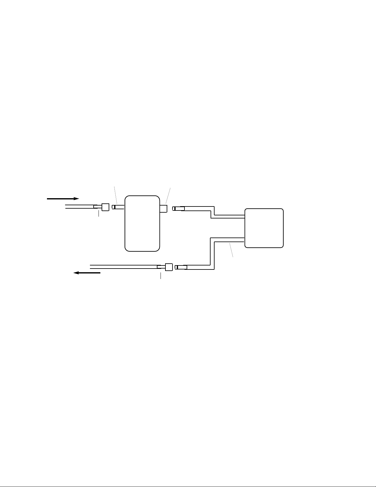
The ECV-1 is supplied with an AC line cord and 12 VDC desktop power supply.
1 Connect the line cord to the socket on the power supply and to the rear auxialiary outlet on the
BFS-MP controller.
2 Connect the 12VDC power supply to the input socket on the front of the ECV-1.
3 Connect the water tubes as shown below:
11
ECV-1
Freezing
Stage
Extension tube with
female connector
TO WASTE
FROM WATER SUPPLY
Extension tube with 1
female connector and
1 universal connector
Female connector
Male connector
Stage has 2 water tubes
with male connectors
EB BFS-MP 6310 04/04
Page 12

PHYSITEMP INSTRUMENTS INC
154 Huron Avenue
Clifton NJ 07013 USA
Tel: 973-779-5577
Fax: 973-779-5954
OPERATING MANUAL
EB FRONTIS EB BFS-VT
BFS-30VT Bath Refrigeration System
 Loading...