

Page 1

OPERATING MANUAL
THERMALERT MONITORING THERMOMETER
TH-8
CONTENTS
Section
1.0 INTRODUCTION
2.0 INITIAL INSTALLATION
3.0 PRECAUTIONS
4.0 DIRECTIONS FOR USE
5.0 REPLACING BATTERIES
6.0 CHECKING CALIBRATION
7.0 AUXILIARY OUTPUT
8.0 SPECIFICATIONS
9.0 TEMPERATURE MEASUREMENT WITH
THERMOCOUPLES
10.0 REPAIRS AND RECALIBRATION
QX My computer\Shared docs\Operating Manuals\TH-8 EB Rev 1
Page 2

Page 3
OPERATING INSTRUCTIONS
THERMALERT MONITORING THERMOMETER, TH-8
1.0 The Physitemp Thermalert series Clinical Monitoring Thermometers are compact, digital
instruments for continuous temperature monitoring. They are all battery operated. Model TH-8
has 3 probe inputs for monitoring of up to 3 sites, and provides a choice of reading in degrees C or
degrees F.
2.0 INITIAL INSTALLATION
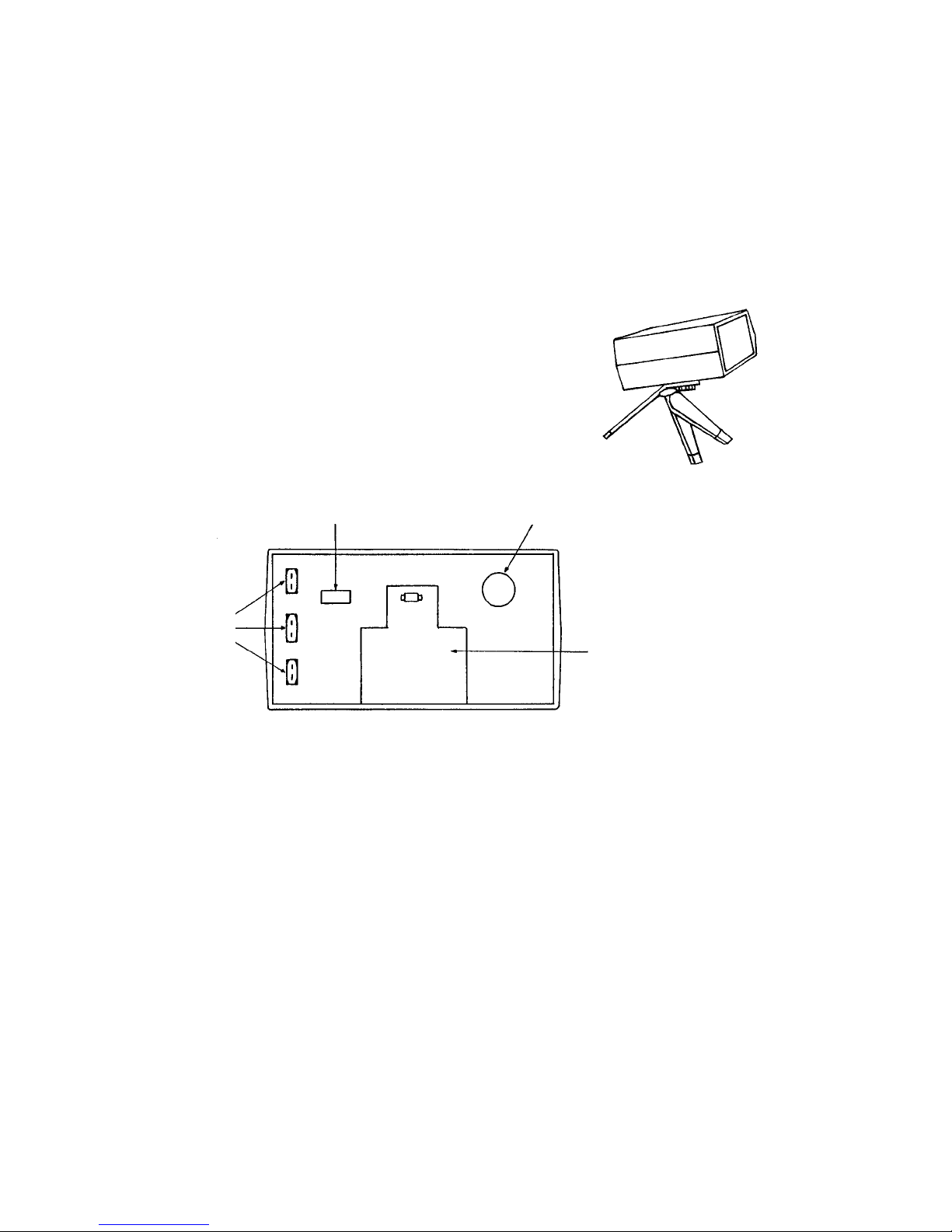
2.1 The TH-8 thermometer is designed to mount as follows:
(a) Flat, on rubber feet provided.
(b) Bench mounting with optional tilt stand (TTS-4).
2.2 Plug any Physitemp type T thermocouple probes into
the blue polarized sockets on the rear of the instrument.
3.0 PRECAUTIONS
3.1 As with any temperature monitoring system, use suitable accepted technique during
electro-surgical procedures to minimize the possibility that the probe cable will serve as an alternate path for radio frequency current and burn the patient.
- Properly locate an adequate electrosurgical dispersive electrode close to the active
surgical site.
- Do not drape the probe cable over grounded metallic surfaces or intertwine it with the
cables of the electrosurgical generator.
3.2 Never pull directly on the probe cable to disconnect.
3.3 Do not gas sterilize or autoclave the instrument.
3.4 Do not immerse the instrument in liquids for cleaning. If necessary, clean the instrument
case with a cloth moistened with a mild non-staining germicidal detergent and warm water.
3
°F or °C SWITCH
OUTPUT SOCKET
BATTERY
COMPARTMENT
INPUT SOCKETS
FOR PROBES OR
EXTENSION CABLES
Page 4
4.0 DIRECTIONS FOR USE
4.1 Connect temperature sensor(s) and cable(s). One, two or three of the numbered INPUTS
may be used.
4.2 Depress the ON-OFF pushbutton. In the ON position an orange indicator will be displayed
within the pushbutton. For several seconds the display should read “1888” as a segment check.
Do not use thermometer if any display numeral is incomplete.
4.3 Depress the numbered INPUT SELECT pushbutton which corresponds with the INPUTS
connection of the sensor to be monitored. A blue indicator will be displayed within the pushbutton selected.
4.4 Monitor temperature. If more than one sensor is connected, switch whenever desired by
depressing the appropriate INPUT SELECT pushbutton. A calibration check is not necessary
before each use.
4.5 Special display indications.
LO BAT - This display appears when battery voltage is low. However, enough power
remains for at least 8 hours of accurate monitoring. The batteries should be
replaced as soon as convenient.
INPUT - This indicates an input circuit problem. Check connections. If necessary,
replace sensor or extension lead.
C or F - Display indicates temperature scale that has been selected with the slide switch
on the back panel.
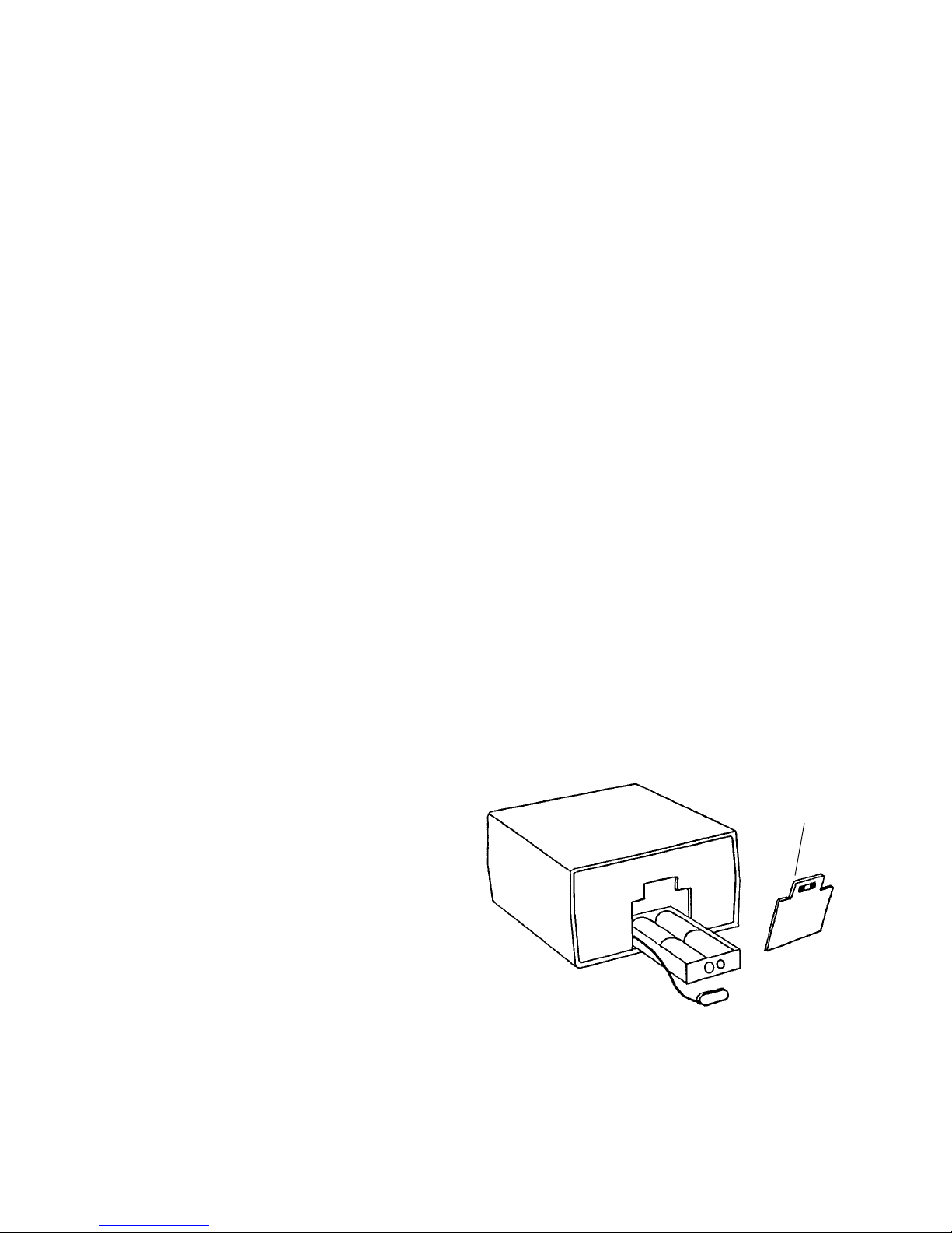
5.0 REPLACING BATTERIES CAUTION: Use only alkaline “C" cell batteries.
5.1 Switch instrument OFF.
5.2 Grasp "squeeze release" on back panel
and pull off battery retainer.
5.3 Remove battery connectors and slide
out battery holder.
5.4 Discard old batteries and replace with
fresh “C" cells.
5.5 Replace battery holder and refit connectors.
5.6 Insert lower edge of battery retainer into bottom of case. While squeezing the "squeeze
release" push retainer in until flush with back of case. Release the squeeze release and push the
battery retainer in until the latch clicks.
4
SQUEEZE RELEASE
Page 5

6.0 CHECKING CALIBRATION
6.1 The Thermalert TH-8 thermometer incorporates an automatic zeroing amplifier which
produces near-perfect stability of calibration. A calibration check is not necessary before each
use. Under normal circumstances, the instrument will provide years of service without requiring recalibration.
6.2 Should it be suspected that the instrument is out of calibration, it may be checked with
the Physitemp type T calibrator (Model CT-3), or if this is unavailable, with an NIST calibrated
thermometer. Verifying instrument calibration with an NIST calibrated thermometer requires
extremely careful technique, an accurate reference standard thermometer, and a reasonably
draft-free location. The following apparatus and supplies are needed:
1 1 - quart thermos flask with 2-hole cork
1 Stirrer
2 NIST traceable mercury in glass thermometer, 0.05°
graduations, partial immersion, 25-50°C (78-122°F) with ice point scale.
2 Physitemp type T temperature probe
Ice made from distilled water
Distilled water
6.3 Preparation of a 0°C icebath:
a) Crush the ice and fill the thermos flask till full. Top off with distilled water. Leave for
30 minutes to allow temperature to stabilize, stirring periodically.
b) Immerse the standard mercury-in-glass thermometer in the ice bath to the immersion
mark on the stem. Stir the bath well and compare with thermometer reading at 0°C with
the correction table supplied with the thermometer. If the error is greater than 0.05 °C,
wait 10 minutes, stir the water bath and remeasure. If the error remains greater, test with
another standard thermometer.
A complete calibration check requires two different measurements, one for each of the temperature ranges of the TH-8.
6.4 CHECKING THE LOW END OF THE TEMPERATURE RANGE
(a) Attach one of the thermocouple sensors to the standard thermometer with an elastic
band. The tip of the sensor should be at the same height as the bulb of the mercury thermometer. Connect the sensor to any input of the TH-8. Immerse the mercury-in-glass thermometer
and thermocouple sensor in the ice bath to the immersion mark, through the cork, and stir well.
Wait 10 minutes. Be sure sensors are not touching side of vessel.
(b) Switch the TH-8 on with the slide switch on the back panel in the degrees F position.
Make sure the “LO BAT” display indication does not appear. Stir the water bath well, and read
the mercury-in-glass thermometer to an accuracy of 0.05 degrees, making sure to minimize parallax errors in the reading. Apply any necessary corrections from the mercury-in-glass ther-
5
Page 6

mometer calibration data, and convert from Centigrade to Fahrenheit if necessary by mutiplying
by 9/5 and adding 32. Compare this reading with that of the Model TH-8. Note both Fahrenheit
readings and any differences on a record sheet.
(c) Move the slide switch to the degrees C position. Stir the water bath another time, and
again compare the standard thermometer reading with that of the instrument. Record both
Centigrade readings and any difference.
6.5 CHECKING THE HIGH END OF THE TEMPERATURE RANGE
(a) Fill the other thermos flask with a mixture of hot and cold water to produce a temperature
of approximately 45°C (113°Fahrenheit).
(b) Using the second standard mercury-in-glass thermometer with the second thermocouple
sensor attached, stir the bath well and wait 10 minutes.
(c) Repeat step 6.4 (b) for checking high end of the range. Recheck the low end of the temperature range to ensure that no change has occurred. If change has occurred, repeat the entire
calibration procedure.
6.7 Allowing for some reading error in mercury themometer (there can be none with the digi tal instrument display) and possible probe error, readings should agree within the limits noted in
section 9.7. This means, as an approximate rule of thumb, that the difference between standard
and instrument readings should not exceed 0.2°C or 0.4°F. The exact error limits depend on the
actual temperature at which the calibration is checked.
6.8 If the instrument appears to be out of calibration based on the foregoing checks, it should
be returned for service (see section 12).
Please note - these calibration instructions will provide a calibration accuracy of not
better than ±0.2°C. A more accurate method requires the use of a temperature controlled oven
and potentiometric facilities in place of the water baths described above. Please consult the
Service Dept. at Physitemp for details.
7.0 THERMALERT AUXILIARY OUTPUT
If your TH-8 has been supplied with the analog output option, the pins are connected as follows:
Pin 2 - analog output positive
Pin 6 - analog output return
6
Page 7

8.0 SPECIFICATIONS
Temperature Range -10 to 60 °C
0 to 140 °F
Degrees F or degrees C user selected
Resolution 0.1°, Fahrenheit or Centigrade
Repeatability 0.1°
Calibration Conforms to National Institute of Standards
and Technology tables (Monograph 125).
Instrument Accuracy 0.1°C (+0.2 degrees) ±1 digit at 25°C ambient
Sensors Any Physitemp type T thermocouple probe.
Ambient Operating Range 15°C - 40°C
Storage 0 to 55° C (32 to 132° F)
Readout 3 1/2 digits, LCD 0.5” high
Display check Automatic “1888” displayed after switch-on tests all segments.
Batteries 4 “C” cells. Alkaline or Mercury may be used.
Carbon-Zinc cells are not recommended.
Battery Life Expectancy 2000 hours continuous (alkaline)
Battery Warning Automatic. LO-BAT appears on display when battery voltage is
low, but several hours of life remain.
Input Check Automatic. INPUT appears on display when input circuit
problem (open sensors) occur.
Auxiliary connection Interface for alarm unit.
Size 3-1/2” H x 6” W x 6 1/4” D
Weight Approximately 3 lbs. with batteries ( 1.4 kg.)
Leakage Current Instrument is isolated from ground and from mounting supports to
5000 volts DC. Low capacitance design minimizes risk caused by
faulty patient grounding during electrosurgery. Leakage is less than
l0µA at 60Hz.
Safety Features Conforms to NFPA 99 Inhalation Anesthetics 1984 (operating
voltage less than l0V), battery operated, suitable for use with flammable anesthetics. ANSI/AAMI Safe Current Limits for Electronic
Apparatus, 1978
7
Page 8

8
9.0 TEMPERATURE MEASUREMENT WITH THERMOCOUPLE SENSORS
9.1 The thermocouple is a simple and widely accepted device for measuring temperature. It
comprises two wires of dissimilar metals fused together to form a junction which produces an electrical output proportional to temperature. The National Institute of Standards and Technology (NIST
Monograph 125, 1974) has tabulated the voltage/temperature relationships of many commonly used
thermocouple pairs; their tables on copper/constantan form the basis for calibration of Physitemp
thermometers.
9.2 At one time, accurate thermocouple temperature measurements needed elaborate potentiometers and reference to a source of known temperature, such as an ice bath. The advent of modern solid state devices has made possible the design of an inexpensive thermocouple thermometer
which is direct reading. The first of these was Bailey thermometer BAT-4, which was designed in
1969 and is now in use throughout the world. Your Thermalert is an advanced version of the original equipment
using the latest low power digital technology and compensated electronic reference circuitry.
9.3 As compared with thermistor sensors which were formerly used exclusively in portable thermometers, thermocouples have these advantages:
(a) wide temperature range, e.g. -200°C to over +1300°C.
(b) High stability of output.
(c) Interchangeability - no recalibration required.
(d) Accuracy traceable to NIST calibrations.
(e) Low cost; users can even make their own sensors.
(f) Microscopic size when needed, as in Physitemp microprobes.
(g) Nearly instant response.
(h) Better measurement accuracy due to low mass with smaller heat loss.
9.4 The main disadvantage of the thermocouple low sensitivity was overcome by the development of auto zeroing amplifiers which are now used in all Physitemp thermometers. This type of
amplifier is essentially drift-free. It makes possible an electronic thermometer which is permanently
calibrated, just like a mercury thermometer. The following notes may help the user to avoid some of
the errors most frequently made in temperature measurement.
9.5 Faulty measurement technique with any type of thermometer can produce errors of several
degrees. Errors attributed to "out of calibration" equipment can often be corrected by a simple
change of technique.
9.6 Thermocouple probes, like all other temperature sensing devices, must be placed so that
they reach, as closely as possible, the temperature of the material to be measured. Probes are tipsensitive, but when measuring the temperatures of liquids, semi-solids or hard surfaces, it is not sufficient to bring only the tip into contact with the material being measured. This is because there
will be loss of heat along both the thermocouple wires and their sheath, so readings will be low.
The effect can be greatly reduced if part of the metal sheath is also placed in contact with the material. In liquids and semi-solids, the tip and sheath are simply immersed; on solid surfaces, part of
the sheath is laid against the surface.
Page 9
9
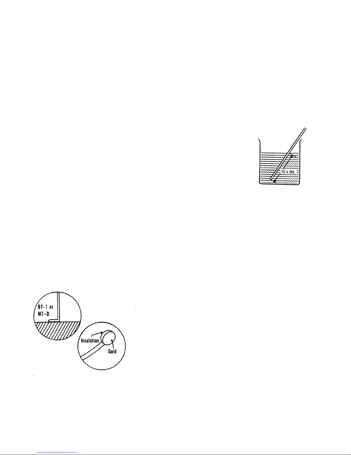
Here is a useful rough rule: Heat leakage effects are substantially reduced when an
amount of probe equal to 10 or more sheath diameters is immersed or laid on the suface.
For example, with a probe of 1/16” diameter, 10 x 1/16” = 10/16 = .625 = the minimum
immersion depth.
9.7 Errors between thermocouple probes. All Physitemp probes and sensors are made with thermocouple wire that has been specially tested to meet our own stringent standards. Our probes are
guaranteed accurate to within 0.1°C in the range 0-50°C. Copper-Constantan (type T) thermocouples
from other manufacturers are normally close to this accuracy provided they are ordered to "special
limits of error," and so are suitable for use with our thermometer. This interchangeability of sensor,
including microprobes, is a major advantage of Physitemp thermocouple thermometers.
9.8 Measurements in Liquids. These are quite easy to make, because
there is good thermal contact between liquid and probe. The latter quickly
reaches liquid temperature and readings can be taken within a few seconds.
However, a liquid which has been heated above or cooled below ambient
will be losing or gaining heat, and convection currents will give rise to
temperature variations of up to several degrees. These variations can be reduced
by vigorous stirring. This simple precaution must always be taken.
9.9 Measurements of Air Temperature. Temperature can vary widely in different parts of a room;
differences of at least several degrees will usually be noted. When a microprobe is used to indicate
air temperature, readings will often fluctuate rapidly, responding to actual temperature changes
caused by air currents. Breathing near the microprobe will produce wide fluctuations. These effects
indicate the sensitivity of the Thermalert/microprobe combination, due to high discrimination of the
instrument and almost instant response of the probe. Fluctuations can easily be eliminated by bringing the probe into contact with a metallic object, thus increasing its effective mass and slowing the
response. Using a larger probe will have the same results.
9.10 Measurements on Solid Surfaces. These are most easily made with surface probes such as our
BT-1 and MT-D. The right-angled tip provides the 10 diameters of probe contact specified in Section
9.6. Straight probes may also be used, provided that
sufficient shaft length is in contact with the surface to
be measured. In general, the smaller the probe, the
more accurately it will measure the surface temperature of a solid. For instance, an MT-29 microprobe, because of its small size, needs to be in contact
with the surface for as little as 1/8”. SST-1 has a 1/4”
gold disc sensor. Gold is an excellent conductor, and
is non-allergenic and non-polluting. It makes a fine
skin surface probe.
SST-1
Page 10

10.0 REPAIRS AND RECALIBRATION
10.1 In the event that a Thermalert Monitoring Thermometer is to be returned for repair and
recalibration, please pack it with care and send it prepaid to:
Physitemp Instruments, Inc
Service Departement
154 Huron Avenue
Clifton, NJ 07013 USA
Please include with the instrument:
(1) A note describing any problems encountered.
(2) The name and telephone of the user or other person we can contact.
(3) The complete return address for shipping.
10.2 A Service Manual for TH-8 is available at additional charge. It includes a schematic,
component locator, trouble-shooting guide and complete calibration instructions. Specific test
equipment is required for recalibration or other servicing. Consult Physitemp Inc. for further
service information by telephone at
10.3 Physitemp Instruments Inc. warrants this instrument to be free from defects in material
and workmanship for 12 months from date of shipment. Repair or replacement will be made at
no charge at the discretion of Physitemp if the defect is not the result of misuse or abuse.
Physitemp accepts no consequential liability for delay in delivery, alleged faulty performance of
the product, or for any other cause.
Cables and probes are considered expendable and are not covered by this warranty. See separate
warranty enclosed with probes.
For your protection, please pack and return items carefully and insure them against possible damage or loss in transit. Physitemp will not be responsible for damage resulting from careless or
inadequate packaging. Please return freight prepaid.
10
Page 11

PHYSITEMP INSTRUMENTS INC
154 Huron Avenue
Clifton, NJ 07013 U.S.A.
Tel: 973-779-5577
Fax: 973-779-5954
e-mail: [email protected]
OPERATING MANUAL
MONITORING
THERMOMETER
THERMALERT TH-8
 Loading...