


PHYSITEMP INSTRUMENTS INC
154 Huron Avenue
Clifton NJ 07013 USA
OPERATING MANUAL
THERMAL SENSITIVITY TESTER
NTE-2A
CONTENTS
Section
1.0 GENERAL DESCRIPTION
2.0 INITIAL INSTALLATION
2.1 Equipment Supplied
2.2 Water Pump and Tank Unit
2.3 Attaching AC Line Cords
2.4 Attaching Water Tubes
2.5 Connecting the Thermal Probe
2.6 Connection to AC and Switch On
3.0 OPERATING INSTRUCTIONS
3.1 Adjusting Base Temperature of Controller
3.2 Measuring Absolute Temperature
3.3 Warning Light
4.0 SPECIFICATIONS
5.0 WARRANTY AND SERVICE
W Shared docs\Operating manuals\ EB NTE-2A, Rev 1 (01/25/07 ECO 10292)
1

THERMAL SENSITIVITY TESTER, NTE-2A
1.0 GENERAL DESCRIPTION
The NTE-2A Controller is a sophisticated testing instrument which provides a means of
accurately measuring a subject’s ability to distinguish small differences in temperature.
The thermal probe is driven by a thermoelectric (Peltier effect) module. These modules have
the unique ability to provide temperature stimuli above and below room temperature.
The temperature of the tip of probe can be adjusted using the SET DIFFERENTIAL TEMP
switch of the controller, which maintains the temperature at the set point. The digital readout
on the controller continuously indicates the actual tip temperature of the probe.
For stable operation, the thermoelectric module requires a trickle of cooling water. This is
supplied from the Pump and Tank Unit.
Although the NTE-2A is a sophisticated electronic system, it requires no technical
knowledge of the user and is designed for high reliability as well as ease of operation.
2

2.0 INITIAL INSTALLATION
2.1 EQUIPMENT SUPPLIED
After unpacking the instruments, check that all parts of the system are present. The boxes
should contain:
1 Controller NTE-2A with AC line cord
1 Thermal Probe
1 Water Pump and Tank Unit, PTU-110A, with 2 water tubes and
AC line cord
1 Operating Manual
2.1 WATER PUMP AND TANK UNIT
Unscrew cap. Fill reservoir with two and a half gallons of distilled water. Add 2 teaspoons or
one tablet of a dehumidifier treatment to prevent the formation of algae in the tank or tubing.
DO NOT OPERATE PUMP UNLESS TANK HAS BEEN FILLED WITH WATER.
PUMP MAY BE DAMAGED IF RUN DRY.
The AC line cord should be connected to the SWITCHED OUTLET on the rear of the
controller. This ensures that the water is always flowing when the controller is turned on.
Check water level periodically during operation to ensure that water level is within three
inches of the lip of the container.
To prevent spills, all water connections are automatically self-sealing when disconnected.
The pump in the PTU-110A Pump and Tank Unit is self-priming. When first started, it will
be noisy for five or ten seconds. This is normal. After the initial clatter, it should operate
quietly and continuously. Occasionally, small air bubbles may collect inside the pump and
result in a buzzing sound. If this becomes unacceptable, we recommend the following
procedure: Check that the tank cap is securely screwed down. Hold the handle on the front of
the unit (the panel with the label) and tilt the whole unit backwards so the label faces up.
The pump will begin to clatter when it is ready to re-prime itself and will stop when returned
to the upright position. Normal operation will then resume.
3
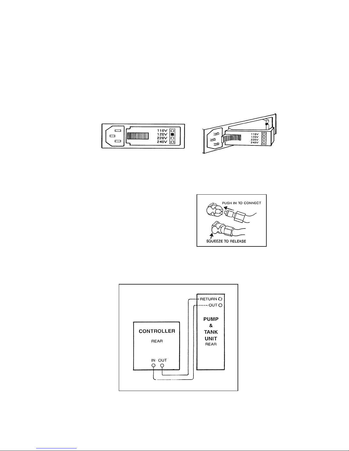
2.3 ATTACHING THE LINE CORD
BEFORE CONNECTING CONTROLLER TO AC POWER SUPPLY CHECK THE
SETTING OF THE VOLTAGE SELECTOR MODULE.
This module is on the back panel, bottom left. There are four settings. Be sure selector is set
for your power requirements. A red indicator should be visible beside the correct voltage in
the list printed on the fuse cover. If the red indicator does not mark the correct voltage, the
card inside the fuse case must be pulled out and reinserted with the proper orientation.
Please note: The controller can be set to 120V or 240V.However the pump and tank unit
does not have voltage setting adjustments. Use PTU-110A for 110/120V and PTU-220 for
220/240V operation.
2.4 ATTACHING WATER TUBES
The Pump and Tank Unit is supplied with two
water tubes. All connections are self-sealing
when disconnected to prevent water spills.
To connect, push in firmly. Squeeze to
disconnect.
Connect one of the tubes from the OUTLET of pump to water INLET on the back panel of
the controller.
Connect the second tube from RETURN of pump to water OUTLET on the controller.
2.5 CONNECTING THE THERMAL PROBE
4
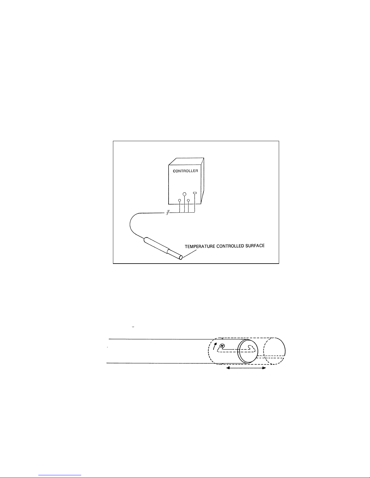
Insert the water tubes from the probe into WATER INLET and OUTLET connectors on the
front panel of the controller. These tubes are interchangeable -- direction of flow is not
important.
Insert polarized electrical connector from stage into POWER OUTPUT socket on front of
the controller. Twist the locking nut in a clockwise direction to lock connector to the
controller.
Insert blue thermocouple connector into socket labelled SENSOR B - STAGE.
Switch SENSOR INPUT to B position.
To protect the tip during shipment and when not in use, a clear protective sheath is provided
with the Thermal Probe. The protective sleeve has a bayonet-type, locking feature and can
be left in place on the probe shaft. To expose the tip, simply twist the sheath until the
retaining screw is in the radial slot and slide the sheath back or forward along the probe
shaft. Twist it again to lock it in place.
Warning: The probe is robust when handled and stored properly. Care should be taken to
ensure that it is not dropped on a hard surface or otherwise severely jarred. It should be
stored in the packing box when not in use.
2.6 CONNECTION TO AC POWER SUPPLY AND SWITCH ON
5

Connect AC line cord from the controller to an AC outlet and turn ON.
A buzzing noise from water pump indicates that pump is running. Remove tank cap and
check that water is flowing.
The power indicator light on the controller and tank unit will light. IF EITHER LAMP
FAILS TO LIGHT, SWITCH OFF and check fuses.
3.0 OPERATING INSTRUCTIONS
3.1 ADJUSTMENT OF BASE TEMPERATURE OF CONTROLLER
All parts of the system must be connected and turned on.
Set all switches under SET DIFFERENTIAL TEMPERATURE to center '0' position.
Depress RUN/SET switch to SET position and hold down while adjusting SET BASE
TEMP with screwdriver. Adjustment may be made to any base temperature between 20 and
30 Centigrade to within 0.1 C.
Release the RUN/SET switch and allow the stage to stabilize at the base set temperature.
This should take one to two minutes. Further slight adjustments to temperature may be made
to provide exact setting.
All further temperature settings can be made using the digital control settings (switches on
the front panel). These settings allow the temperature of the stage to be incremented or
decremented in 5, 1 degree or 1/10 steps from the base temperature.
3.2 MEASURING ABSOLUTE TEMPERATURE
The digital display of the controller may be used as a readout for an external sensor (Type T,
copper-constantan thermocouple with miniature t/c plug.)
Connect a thermocouple sensor into socket marked SENSOR A - EXTERNAL.
Switch SENSOR INPUT to A. Read absolute temperature on controller display.
During measurement with external sensor, all power to the Thermal Probe is disconnected.
Switch SENSOR INPUT back to B and allow the stage temperature to stabilize again.
3.3 WARNING LIGHT
As a protective feature, both audible and visual warnings of operating failure are provided.
SWITCH OFF IMMEDIATELY IF WARNING LIGHT COMES ON OR IF BUZZER
ALARM IS HEARD.
In the event of failure, consult manufacturer for further information:
Physitemp Instruments Inc. 973-779-5577 or e-mail physitemp@aol.com
4.0 SPECIFICATIONS
6

CONTROLLER SPECIFICATIONS
BASE TEMPERATURE RANGE Continuously adjustable over range 20 - 30 C with flat
bladed screwdriver
CONTROL RANGE 20.5either side of nominal base temperature point in
switchable 0.1 steps. 45 C max.
CONTROL ACCURACY 0.1 C
DIGITAL READOUT: Resolution 0.1 C
Accuracy 0.1, digit
AMBIENT OPERATING RANGE 15 - 45 C
INPUT POWER REQUIREMENTS 100 - 120V AC, 60Hz, 100W
200 - 240V AC, 50Hz, 100W
SIZE 8" high x 7" wide x 15" deep
WEIGHT 28 lbs
OTHER FEATURES Spring loaded switch indication of set-point Safety
shutdown with warning lamp in case of fault condition
such as thermocouple sensor breakage, lack of cooling
water or electronics failure. Self-sealing water connectors.
Auxiliary AC switched output.
THERMAL PROBE SPECIFICATIONS
SIZE 6.5” long x 5/8” dia. Total length with cable, 6 feet approx
WEIGHT 0.5 lb
TEMPERATURE CONTROLLED 0.5” diameter
SURFACE AREA
RANGE 0 - 45 C
Note: Sustained exposure to temperatures over 46 C can
cause burns. This equipment is not intended for use at
temperatures over 45 C
RESPONSE TIME Less than 4 seconds in heating or cooling
OTHER FEATURES Built-in feedback sensor, type T, copper-constantan.
Self sealing water connectors.
5.0 WARRANTY AND SERVICE
7

5.1 WARRANTY
Physitemp Instruments Inc. warrants this system to be free from defects in material and workmanship
for 12 months from the date of shipment. Repair or replacement will be made at no charge at the
discretion of Physitemp if the defect is not the result of misuse or abuse. Physitemp accepts no
consequential liability for delay in delivery, alleged faulty performance of the product, or any other
cause.
5.2 REPAIRS AND RECALIBRATION
For technical or applications information on this instrument call 973-779-5577 or e-mail
physitemp@aol.com
In the event that any part of this system is to be returned for repair or recalibration, please pack it with
care and send it prepaid via Federal Express to:
Service Department
PHYSITEMP INSTRUMENTS INC.
154 Huron Avenue
Clifton, NJ 07013 U.S.A.
Please include with the instrument:
1. A note descri bing any problems encountered.
2. The name and telephone number of a person we can contact.
3. The complete return address for shipping.
For your protection, please pack the item carefully and insure against possible damage or lo ss.
Physitemp will not be responsible for damage resulting from careless packaging. Please return freight
prepaid.
8
 Loading...