

Page 1
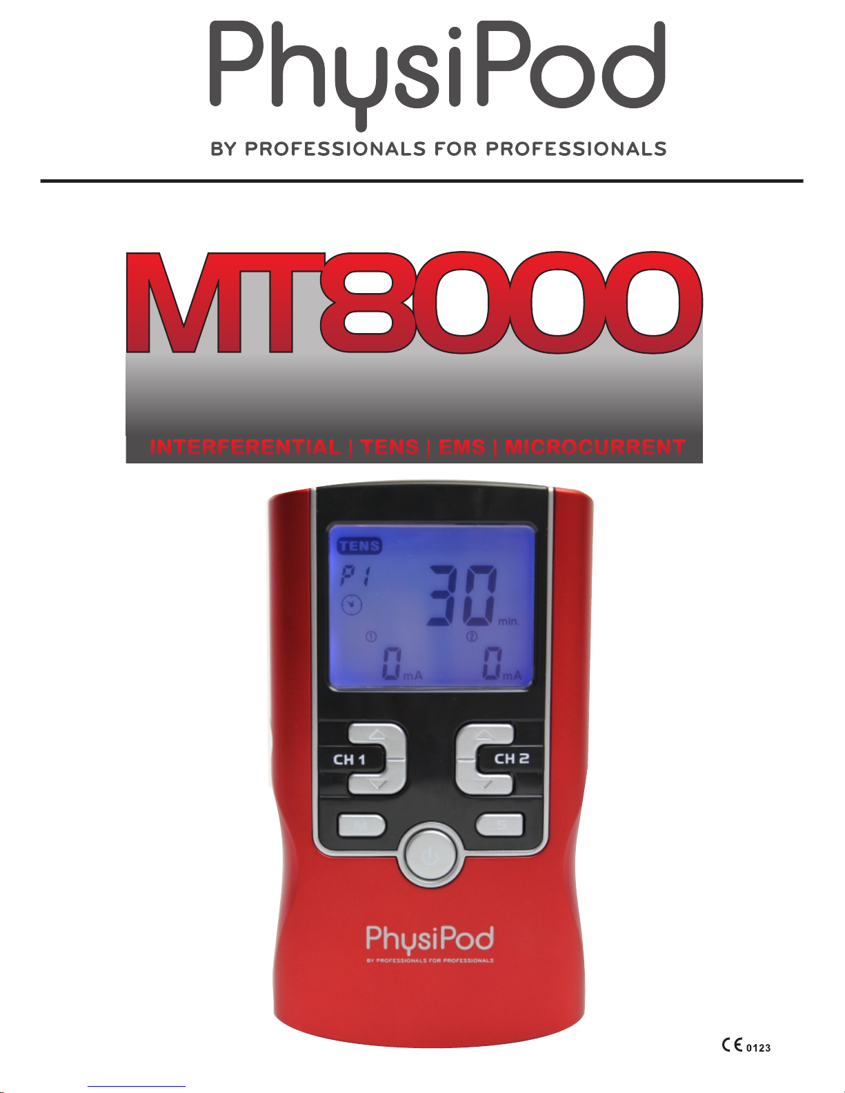
INSTRUCTION MANUAL
MULTI MODALITY
ELECTRICAL STIMULATOR
INTERFERENTIAL | TENS | EMS | MICROCURRENT
Page 2

Table of Contents
1.Safety information…..………………………………………..
4
1.1 General description
1.2 Medical background
1.3 Indication for use
1.4 Contraindications
1.5 Warnings, Cautions, Adverse Reactions
2. Presentation ……………………………………………...… 13
2.1 Front and Rear panel
2.2 LCD display
3. Specification…………………………………………………
15
3.1 Accessories
3.2 Technical information
3.3 The waveforms of the stimulation programs
4. Instruction for use …………………………………………..
23
4.1 Battery
4.2 Connect electrodes to lead wires
4.3 Connect lead wires to device
4.4 Electrode
4.5 Turn ON
4.6 Select the Therapeutic Mode
4.7 Steps to set a new program
4.8 Adjust Channel Intensity
4.9 Lock the button
4.10 Stop the treatment
4.11 Turn OFF
4.12 Low battery indicator.
5. Program……………………………………………………….36
6. Cleaning and Care………………………………………….. 37
6.1 Tips for skin care
6.2 Cleaning the device
6.3 Electrodes
6.4 Cleaning the Electrodes cords
6.5 Maintenance
7. Troubleshooting…………………………………………......41
8. Storage……………………………………………………….. 42
9 .Disposal……………………………………………………….43
10. Electromagnetic Compatibility (EMC) Tables……….....43
11. Glossary symbols…………………………………...........
48
12. Warranty…………………………………………………..…49
.
3
Page 3

1. Safety information
1.1 General
M T 8 0 0 0 E l e c t r i c a l S t i m u l a t o r i s a p or ta bl e
electrotherapy device featuring four therapeutic
m o d e s : Tr an sc ut an e o u s E l e c t r ic al Ne rv e
S t i m u l a t o r , E l e c t r i c a l M us cl e S t i m u l a t i o n
Interferential, and Microcurrent,which are used for
pain relief and electrical muscle stimulation. The
sti m ulator sends ge n tle el ectrica l curr ent to
underlying nerves and muscle group via electrodes
applied on the skin. The parameters of device are
controlled by the press buttons. Its intensity level is
adjustable according to the needs of patients.
EXPLANATION OF TENS
Transcutaneous Electrical Nerve Stimulation (TENS)
is a non-invasive, drugfree method of controlling
pain. TENS uses tiny electrical impulses sent through
the skin to nerves to modify your pain perception.
TENS does not cure any physiological problem; it
only helps control the pain. TENS does not work for
everyone; however, in most patients it is effective in
reducing or eliminating the pain, allowing for a return
to normal activity.
EXPLANATION OF EMS
E l e c tr i c a l M u sc l e S t i m u l a ti o n ( E M S ) i s a n
internationally accepted and proven way of treating
muscular injuries. It works by sending electronic
pulses to the muscle needing treatment; this causes
1.2 Medical background
4
Page 4

the muscle to exercise passively. It is a product
derived from the square waveform (ladder-sha
ped). Through the square wave pattern it is able to
work dire ctly on muscle motor neurons. This device
has low frequency and this in conjunction with the
square wave pattern allows direct work on muscle
groupings. This is being widely used in hospitals and
sports clinics for the reatment of muscular injuries
and for the re-education of paralyzed muscles, to
prevent atrophy in affected muscles and improving
muscle tone and blood circulation.
EXPLANATION OF IF
Interferential Stimulation (IF) is an anti-inflammatory
based treatment modality. Interferential stimulation is
characterized by two alternating-current sine waves
or square waves of differing frequencies that “work”
together to produce an interferential current that is
also known as a beat pulse or alternating modulation
frequency. One of the two currents is usually held at
4,000 Hz, and the other can be held constant or
varied over a range of 4,001 to 4,100 Hz. Because of
the frequency, the interferential wave meets low
impedance when crossing the skin to enter deep into
soft tissues. The interferential currents reportedly
can stimulate sensory, motor, and pain fibers. These
large impulse fibers interfere with the transmission of
pain messages at the spinal cord level. This deep
tissue penetration stimulates parasympathetic nerve
fibers for increased blood flow and edema reduction.
It utilizes the low electric-current to stimulate muscle
nerves to achieve the symptomatic relief of chronic
intractable pain, post-traumatic pain, and postsurgical pain.
5
Page 5

EXPLANATION OF MICROCURRENT
Microcurrent stimulation is a type of therapy in which
very low current is sent into the cells of the body.
Microcurrent is a very faint current that is so small it is
measured in millionths of an amp (Microamps).
Human cells generate a current that is in the
microamp range which is why you can't feel it-the
current is so low it doesn't stimulate the sensory
nerves.
Microcurrent is a physiological electric modality that
increases ATP (energy) production in the cells of your
body. This dramatically increases the tissue's healing
rate. The i mmediate respons e t o the corr e c t
m i c r oc ur r e n t f r e q u e nc y s u gg es t s t ha t o t h e r
mechanisms are involved as well. The exact effects
or changes in the tissue are unmistakable; scars will
often suddenly soften; trigger points often become
less painful within minutes when the “correct”
frequency is applied. In many situations the changes
seen seem to be long lasting and in many cases
permanent.
1.3 Indication for use
MT8000 electrical stimulator may be used for
the following conditions:
1) Symptomatic relief of chronic intractable pain;
Post traumatic pain; post surgical pain.
2) Relaxation of muscle spasm.
3) Increase of blood flow circulation
4) Prevention or retardation of disuse atrophy
5) Muscle re-education
6) Maintaining or increasing range of motion.
7) Immediate post-surgical stimulation of calf
muscles to prevent venous thrombosis
6
Page 6

IMPORTANT SAFETY INFORMATION!
Read instruction manual before operation. Be sure to
comply with all “Contraindications”, Warnings”,
“Cautions” and “Adverse reactions” in the manual.
Failure to follow instructions can cause harm to user
or device.
1.4 Contraindications
1) This device should not be used for symptomatic
local pain relief unless etiology is established or
unless a pain syndrome has been diagnosed.
2) This device should not be used when cancerous
lesions are present in the treatment area.
3) Stimulation should not be applied over swollen,
infected, inflamed areas or skin eruptions (e.g. phl
ebitis, thrombophlebitis, varicose veins, etc.).
4) Electrodes must not be applied to sites that might
cause current/stimulation to flow through the
carotid sinus region (anterior neck) or
transcerebrally (through the head).
5) Do not use this device if the patient has a demand type cardiac pacemaker or any implanted
defibrillator.
6) This device should not be used over poorly
enervated areas.
7) Epilepsy
8) Serious arterial circulatory problems in the lower
limbs
9) Abdominal or inguinal hernia
10) Do not use this device if you have heart disease
without consulting your physician.
7
Page 7

1.5 Warnings, Cautions and Adverse Reactions
WARNINGS:
1) This device should be used only under the
continued supervision of a licensed physician.
2) The long-term effects of chronic electrical
stimulation are unknown. Electrical stimulation
devices do not have any curative value .
3) TENS is a symptomatic treatment and, as such,
suppresses the sensation of pain, which would
otherwise serve as a protective mechanism.
4) Safety has not been established for the use of
therapeutic electrical stimulation during
pregnancy. Do not use during pregnancy unless
directed by your physician.
5) Electrical stimulation is not effective for pain of
central origin.
6) Electronic monitoring equipment (such as ECG
monitors and ECG alarms) may not operate
properly when electrical stimulation is in use.
7) Stimulation should not be applied over the
carotid sinus nerves, particularly in patients with a
known sensitivity to the carotid sinus reflex.
8) Stimulation should not be applied over the neckor
mouth. Severe spasm of the laryngeal and
pharyngeal muscles may occur and the contractions
may be strong enough to close the airway or cause
difficulty in breathing.
9) Stimulation should not be applied transthoracically
in that the introduction of electrical current into the
heart may cause cardiac arrhythmias.
10) Stimulation should not take place while the user is
connected to high-frequency surgical equipment,
it may cause burn injuries on the skin under the
electrodes, as well as problems with the stimulator.
8
Page 8

11) Do not use the stimulator in the vicinity of
shortwave or microwave therapy equipment, since
this may affect the output power of the stimulator.
12) Never use in environments with high humidity such
as in the bathroom or when having a bath or shower.
13) Caution should be used in applying electrical
stimulation to patients suspected of having heart
disease. Further clinical data is needed to show
there are no adverse results.
14) Never use near the heart. Stimulation electrodes
should never be placed anywhere on the front of
the thorax (marked by ribs and breastbone), but
above all not on the two large pectoral muscles.
Here it can increase the risk of ventricular
fibrillation and lead to cardiac arrest.
15) Electrodes should not be placed over the eyes, in
the mouth, near the genitals or internally.
16) Never use on the areas of the skin which lack
normal sensation
17) Apply the electrodes to clean, dry, and unbroken
skin only.
18) Keep electrodes separate during treatment,
electrodes in contact with other could result in
improper stimulation or skin burns.
19) Keep the stimulator out of reach of children.
20) Consult your doctor if you are in any doubt
whatsoever.
CAUTIONS:
1) Federal law (USA) restricts this device to sale by
or on the order of a physician.
2) For single patient use only.
3) Keep yourself informed of the contraindications.
9
Page 9

4) This stimulator not intended for unattended,
personal use by patients who have noncompliant,
emotionally disturbed, dementia, or low IQ.
5) Read, understand, and practice the warnings,
cautions and operating instructions. Know the
limitations and hazards associated with using any
device. Observe the precautionary and operational
decals placed on the unit. Always follow the
operating instructions prescr ibed by your healthcare
practitioner.
6) The instruction of use was listed; any improper use
may be dangerous.
7) Do not use this device for undiagnosed pain
syndromes until consulting a physician.
8) Patients with an implanted electronic device, such
as a cardiac pacemaker, implanted defibrillator, or
any other metallic or electronic device should not
use this device without first consulting a doctor.
9) Stimulation delivered by this device may be
sufficient to cause electrocution. Electrical current
of this magnitude must not flow through the thorax
or across the chest because it may cause a cardiac
arrhythmia.
10) Do not place electrodes on the front of the throat as
spasm of the Laryngeal and Pharyngeal muscle may
occur. Stimulation over the carotid sinus (neck
region) may close the airways, make breathing
difficult, and may have adverse effects on the heart
rhythm or blood pressure.
11) Do not place electrodes on your head or at any sites
that may cause the electrical current to flow
transcerebrally (through the head).
12) Patients with heart disease, epilepsy, cancer or any
other health condition should not use this device
without first consulting a physician.
10
Page 10

13) Some patients may experience skin irritation or
hypersensitivity due to the electrical stimulation or
silicone rubber. If rash develops or pain persists,
discontinue use and consult a doctor.
14) Electrode placement and stimulation settings
should be based on the guidance of prescribing
practitioner.
15) Effectiveness is highly dependent upon patient
selection by a person qualified in the management
of pain afflicted patients.
16) Isolated cases of skin irritation may occur at the
site of the electrode placement following long-term
application. If this occurs, discontinue use and
consult your physician.
17) The electrodes are only to be placed on healthy skin.
Avoid skin irritation by ensuring that good contact is
achieved between electrodes and skin.
18) If the stimulation levels are uncomfortable or
become uncomfortable, reduce the stimulation
Intensity to a comfortable level and contact your
physician if problems persist.
19) This device should not be used while driving,
operating machinery, close to water, or during any
activity in which involuntary muscle contractions
may put the user at undue risk of injury.
20) Never use the device in rooms where aerosols
(sprays) are used or pure oxygen is being
administered.
21) Do not use it near any highly flammable substances,
gases or explosives.
22) Do not use this device at the same time as other
equipment which sends electrical pulses to your
body.
23) Do not confuse the electrode cables and contacts
with your headphones or other devices, and do no t
connect the electrodes to other devices .
11
Page 11

24) Do not use sharp objects such as pencil point or
ballpoint pen to operate the buttons on the control
panel.
25) Inspect Applicator cables and associated
connectors before each use.
26) Turn the device off before applying or removing
electrodes.
27) Electrical stimulators should be used only with the
leads and electrodes recommended for use by the
manufacturer
28) This device has no AP/APG protection. Do not use
it in the presence of explosive atmosphere and
flammable mixture.
Adverse Reactions:
1) Skin irritation from the electrode gel and electrode
burns are potential adverse reactions. If skin
irritation occurs, discontinue use and consult you r
physician.
2) If the stimulation levels are uncomfortable, reduce
the stimulation Intensity to a comfortable level and
contact your physician if problems persist.
12
Page 12
2. Presentation
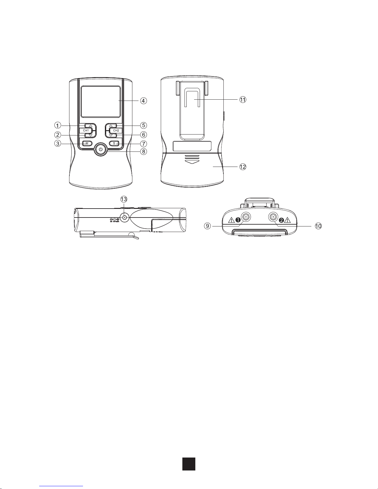
2.1 Front and Rear Panel
1) Increasing the output intensity of channel 1 [▲ . To
set the application program and the parameter of
the waveform in the setting state.
2) Decreasing the output intensity of channel 1 [▼].
To set the application program and the parameter
of the waveform in the setting state. To unlock the
current treatment program.
3) Therapeutic mode selection [M]. Stop the treatment.
Exit setting mode to the user interface.
4) LCD display: Shows the operating state of the device.
5) Increasing the output intensity of channel 2 [▲]. To
set the application program and the parameter of
the waveform in the setting state.
6) Decreasing the output intensity of channel 2 [▼]. To
set the application program and the parameter of
the waveform in the setting state. To unlock the
current treatment program.
]
13
Page 13
7) Parameter Selection [S]: press the button to
enter setting state; you can select the difference
parameters in conjunction with [▲] and [▼].
8) Turn OFF/ON: press the [ ]button to turn on th e
device or keep [ ] button for approx.3 seconds
to turn off the device.
9) Output socket: electric signal output afte r
connection of the cable with adhesive electrodes
channel 1
10) Output socket: electric signal output after
connection of the cable with adhesive electrodes
channel 2
11) Belt Clip
12) The battery compartment cover for opening
13) Adapter Receptacle
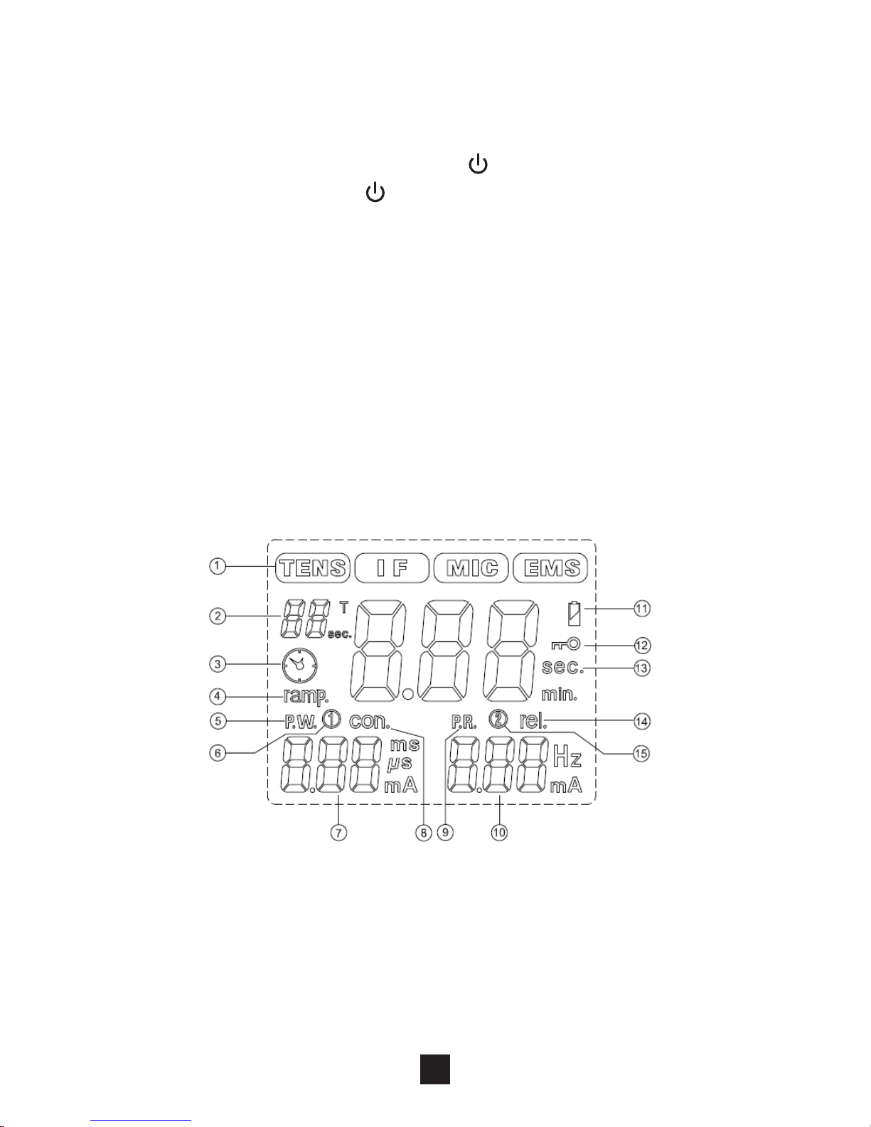
2.2 LCD display
1) Display therapeutic mode
2) Display therapeutic program or Display the cycle
time for TENS, IF and MIC therapeutic mode in
setting state.
3) Timer symbol
4) EMS waveform of ramp up and ramp down time
5) Display of waveform pulse width
14
Page 14

6) Display the channel 1
7) Display numbers of the output intensity for channel
1(CH1); Display numbers of waveform pulse width
or EMS waveform of contraction (working) time in
setting state.
8) EMS waveform of contraction (working) time
9) Display of waveform pulse rate
10) Display numbers of the output intensity for channel
2(CH2); Display numbers of waveform pulse rate
or EMS waveform of relaxation time in setting state.
11) Low-battery indicator
12) The device is locked indicator
13) Display numbers of the treatment time or EMS
waveform of ramp up and ramp down time
14) EMS waveform of relaxation time
15) Display the channel 2
3. Specification
3.1 Accessories
No DESCRIPTION Q’TY
1 Electrical stimulator device 1 piece
2 Electrodes Leads 2 pieces
3 40*40 mm Adhesive Electrodes 4 pieces
4 9V Battery, type 6LR61 1 piece
5 Instruction Manual 1 piece
6 Carrying case 1 piece
15
Page 15
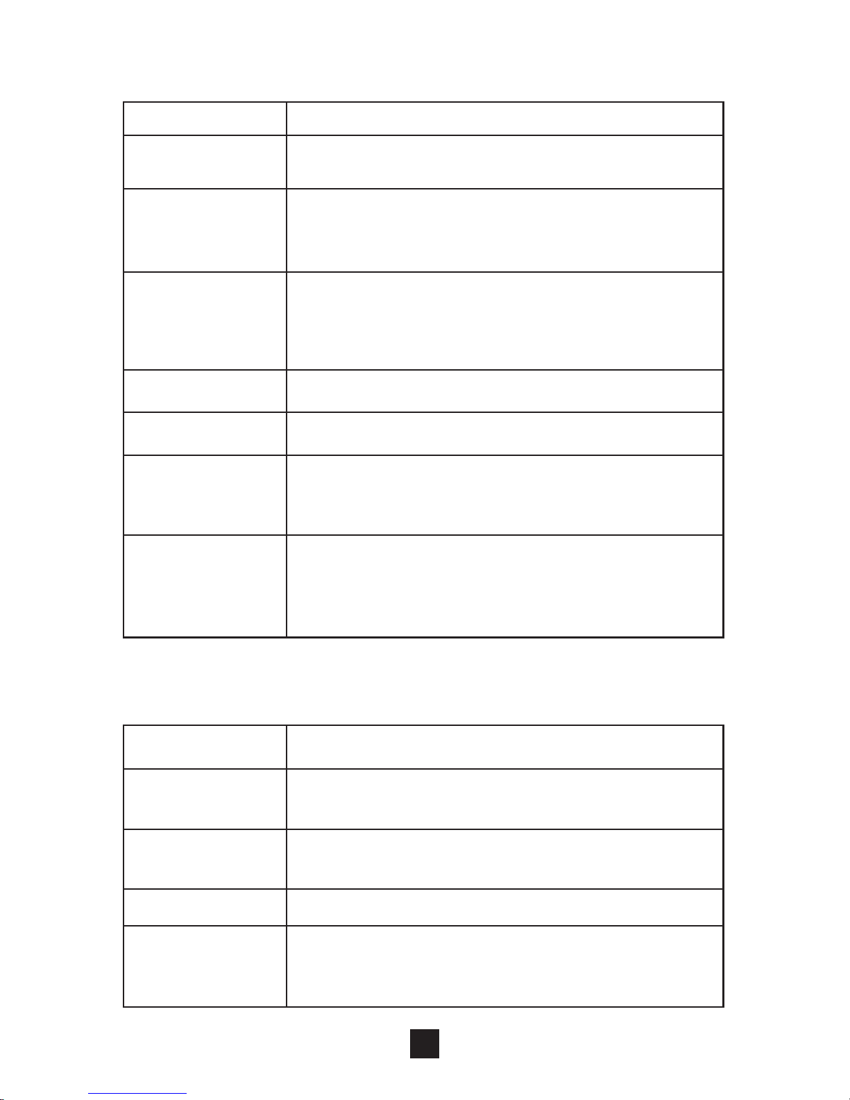
3.2 Technical information
Channel
Dual, isolated between channels
Power supply
9.0 V DC -1 *6LR61 battery
Adapter output:9.0Vdc, 800mA
Operating
conditions
5°C to 40°C( 41 to 104 with a relative
humidity of 30%-75%, atmospheric
pressure from 700 to 1060 Hpa
℉ ℉)
Storage
conditions
-10°C to 50°C (14 to 122 with a
relative humidity of 10%-90%,atmospheric
pressurefrom 700 to 1060 Hpa
℉ ℉)
Dimensions
4.5×2.55×0.9 inches(L*W*H)
Weight
0.28 lbs(With battery)
Tolerance
There may be a ±5% tolerance of all
setting and ±10% tolerance of output
of intensity.
Timer
Adjustable, from 1 to 60 minutes or
continuous, Adjustable in 1minutes each
step. Treatment time countdown
automatically.
Waveform
Mono-phase square pulse wave
Pulse
amplitude
Adjustable, 0~100mA peak at 1000 ohm
Load each channel, 1mA/Step.
Pulse Width
Adjustable, from 50 to 300us
microseconds, 10μS/step
Pulse Rate
Adjustable, from 1 to 150 Hz, 1 Hz/step
Technical specifications for Transcutaneous
Electrical Nerve Stimulator (TENS) mode
Burst (P1)
Burst rate: Adjustable, 0.5 ~ 5Hz;
0.1Hz/step Pulse width adjustable,
50~300μS Frequency fixed = 100 Hz
16
Page 16
Technical specifications for Electrical Muscle
Stimulation (EMS) mode
Waveform
Mono-phase square pulse wave
Pulse
amplitude
Adjustable, 0~100mA peak at 1000 ohm
Load each channel, 1mA/Step.
Pulse Width
Adjustable, from 50 to 300μS
microseconds, 10μS/step.
Pulse Rate
Adjustable, from 1 to 150 Hz, 1 Hz/step
Contraction time
Adjustable, 1~30 seconds , 1 Sec./ step
Relaxation
(OFF)time
Adjustable, 0~60 seconds , 1 Sec./ step
Ramp time
Adjustable, 1~6 seconds, 1 Sec. / step,
The “On” time will increase and decrease
in the setting value.
17
Normal (P2)
The pulse rate and pulse width are
adjustable. It generates continuous
stimulation based on the setting value.
Pulse Width
Modulation
(P3)
The pulse width is automatically varied in
a cycle time. The pulse width is decreased
from its original setting to 60% in setting
cycle time, and then increased from 60%
to its original setting in nest setting cycle
time. In this program, pulse rate (1 to
150Hz), pulse width (50 to 300us) and
cycle time (5 to 30 sec) are fully adjustable.
Pulse Rate
Modulation
(P4)
The pulse rate is automatically varied in a
cycle time. The pulse rate is decreased
from its original setting to 60% in setting
cycle time, and then increased from 60%
to its original setting in nest setting cycle
time. In this program, pulse rate (1 to
150Hz), pulse width(50 to 300us) and
cycle time (5 to 30 sec) are fully adjustable.
Page 17
Alternate (P2)
The Stimulation of the CH2 will occur after
the 1st working of CH1 is completed. In
this program, The “ON” time including
“Contraction”, “Ramp Up” and “Ramp
Down” time. The OFF Time should be
equal or more than the ON Time
ON TIME=Contraction + Ramp up + Ramp
down OFF TIME≥ON TIME
Delay (P3)
The Stimulation of the CH2 will occur after
the 1st working of CH1 is started+ Delay
Time. Delay time is adjustable form 1 to
10 sec. In this program, The “ON” time
including “Contraction”, “Ramp Up” and
“Ramp Down” time.
ON TIME=Contraction + Ramp up + Ramp
down
Technical specifications for Interferential (IF)
mode
Waveform
Bi-phase square pulse
Pulse
amplitude
Adjustable, 0~70mA peak to peak at
1000 ohm Load each channel, 1mA/Step.
Pulse Rate
Channel 1 – Fundamental frequency:
4000 Hz fixed Channel 2 – Selectable
frequency: 4001 to 4150 Hz Interference
frequency: 1 to 150 Hz.
Phase Width
125μS
18
Synchronous
(P1)
Stimulation of both channels occurs
synchronously. The “ON” time including
“Contraction”, “Ramp Up” and “Ramp
Down” time.ON TIME=Contraction +
Ramp up + Ramp down
Page 18

19
P1
The pulse rate of the CH1 is fixed in
4000Hz; CH2 pulse rate is increased from
4001Hz to 4010Hz in a cycle time, and
then decreased from 4010Hz to 4001Hz
in nest setting cycle time. In this program,
CH2 interference frequency is varied from
1Hz to 10Hz, cycle time (5 to 30 sec) is
fully adjustable. CH 2 pulse rate=4000Hz+
Interference frequency
The pulse rate of the CH1 is fixed in
4000Hz; CH2 pulse rate is increased from
4001Hz to 4150Hz in a cycle time, and
then decreased from 4150Hz to 4001Hz
in nest setting cycle time. In this program,
CH2 interference frequency is varied from
1Hz to 150Hz, cycle time (5 to 30 sec) is
fully adjustable. CH 2 pulse rate=4000Hz+
Interference frequency
P2
The pulse rate of the CH1 is fixed in
4000Hz; CH2 pulse rate is increased from
4080Hz to 4150Hz in a cycle time, and
then decreased from 4150Hz to 4080Hz
in nest setting cycle time. In this program,
CH2 interference frequency is varied from
80Hz to 150Hz, cycle time (5 to 30 sec) is
fully adjustable. CH 2 pulse rate=4000Hz+
Interference frequency
P3
P4
The pulse rate of the CH1 is fixed in
4000Hz; CH2 pulse rate is automatically
varied in a cycle time. Interference
frequency is increased from its original
setting to 60% in setting cycle time, and t
hen decreased from 60% to its original
setting in nest setting cycle time. In this
program, CH2 interference frequency (2
to 150Hz) and cycle time (5 to 30 sec) are
fully adjustable. CH 2 pulse rate=4000Hz+
Interferencefrequency
Page 19
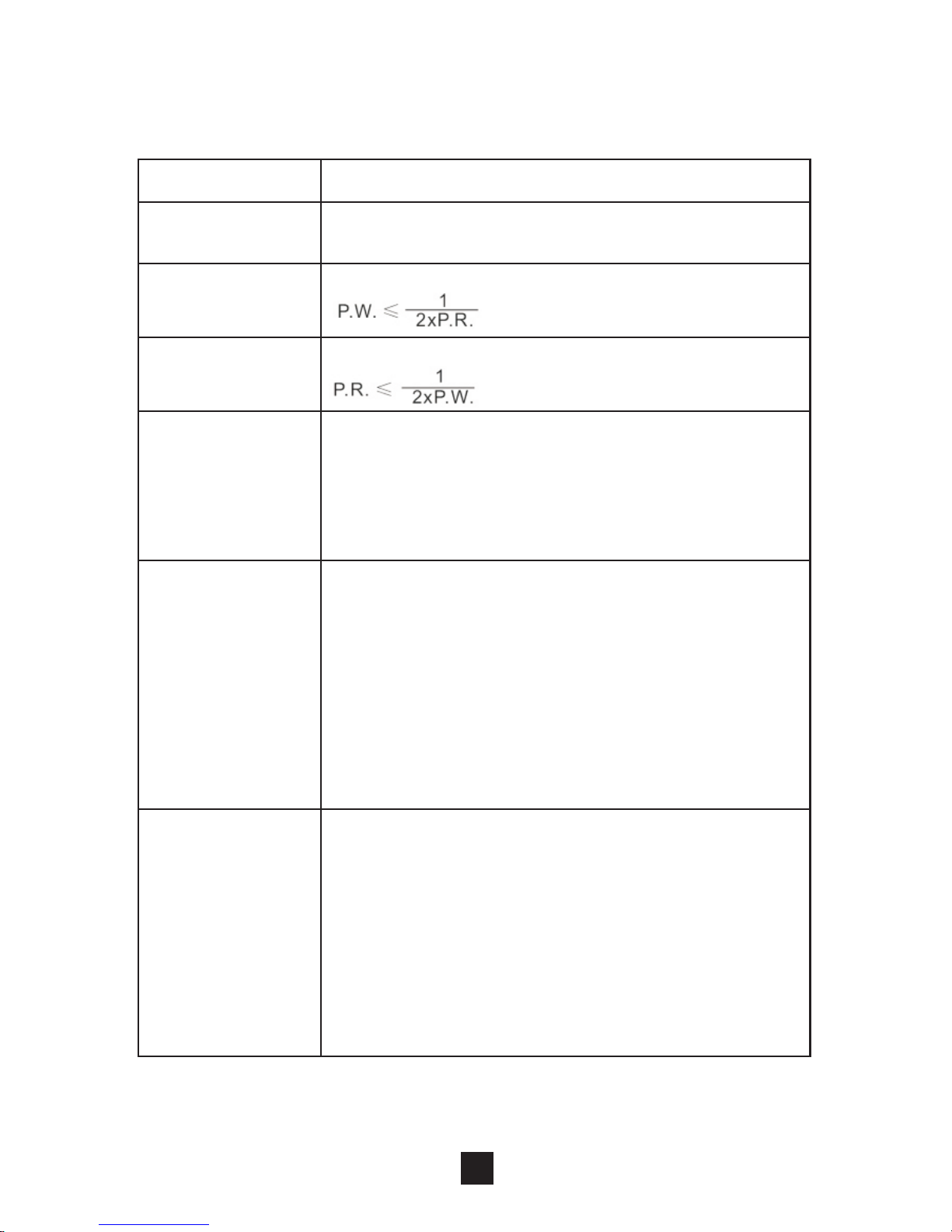
Constant(P1)
Constant stimulation based on setting
value. Only pulse width, pulse rate and
timer are adjustable in this program.
“Constant” is equal to the “Normal” mode
of a TENS therapeutic mode
Pulse Width
Modulation
(P2)
The pulse width is automatically varied
in a cycle time. The pulse width is
decreased from its original setting to 60%
in setting cycle time, and then increased
from 60% to its original setting in nest
setting cycle time. In this program, pulse
rate (1 to 150Hz), pulse width (2 to 200ms)
and cycle time (5 to 30 sec) are fully
adjustable.
Pulse Rate
Modulation
(P3)
The pulse rate is automatically varied in
a cycle time. The pulse rate is decreased
from its original setting to 60% in setting
cycle time, and then increased from 60%
to its original setting in nest setting cycle
time. In this program, pulse rate
(1 to 150Hz), pulse width (2 to 200ms)
and cycle time (5 to 30 sec) are fully
adjustable.
20
Technical specifications for Microcurrent (MIC)
mode
Waveform
Mono-phase square pulse wave
Pulse
amplitude
Adjustable, 0~0.7mA peak at 1000 ohm
Load each channel, 0.01mA/Step
Pulse Width
(P.W.)
Adjustable, from 2 to 200ms, 1ms/step
Pulse Rate
(P.R.)
Adjustable, from 1 to 150 Hz, 1 Hz/step
Page 20
CH1
CH2
Pulse Width Modulation
Pulse Rate Modulation
21
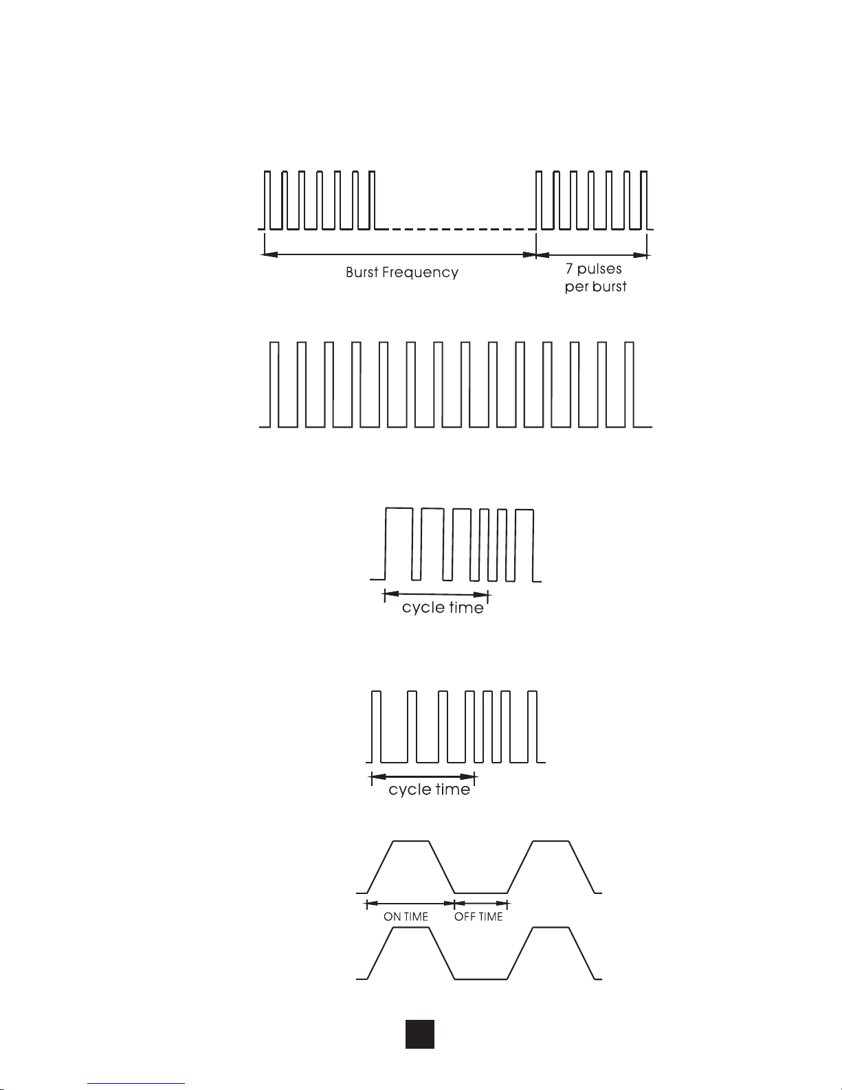
3.3 The waveforms of the stimulation programs
Burst
Normal
Synchronous
Page 21
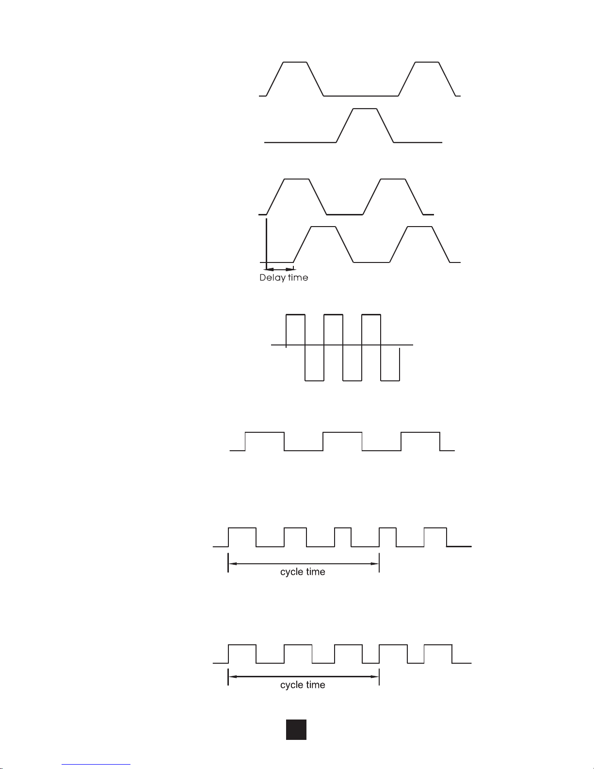
Delay
Interferential
22
Alternate
CH1
CH2
CH1
CH2
Microcurrent(Constant) (P1)
Microcurrent Pulse Width
Modulation P2)(
Microcurrent Pulse Rate
Modulation(P3)
Page 22
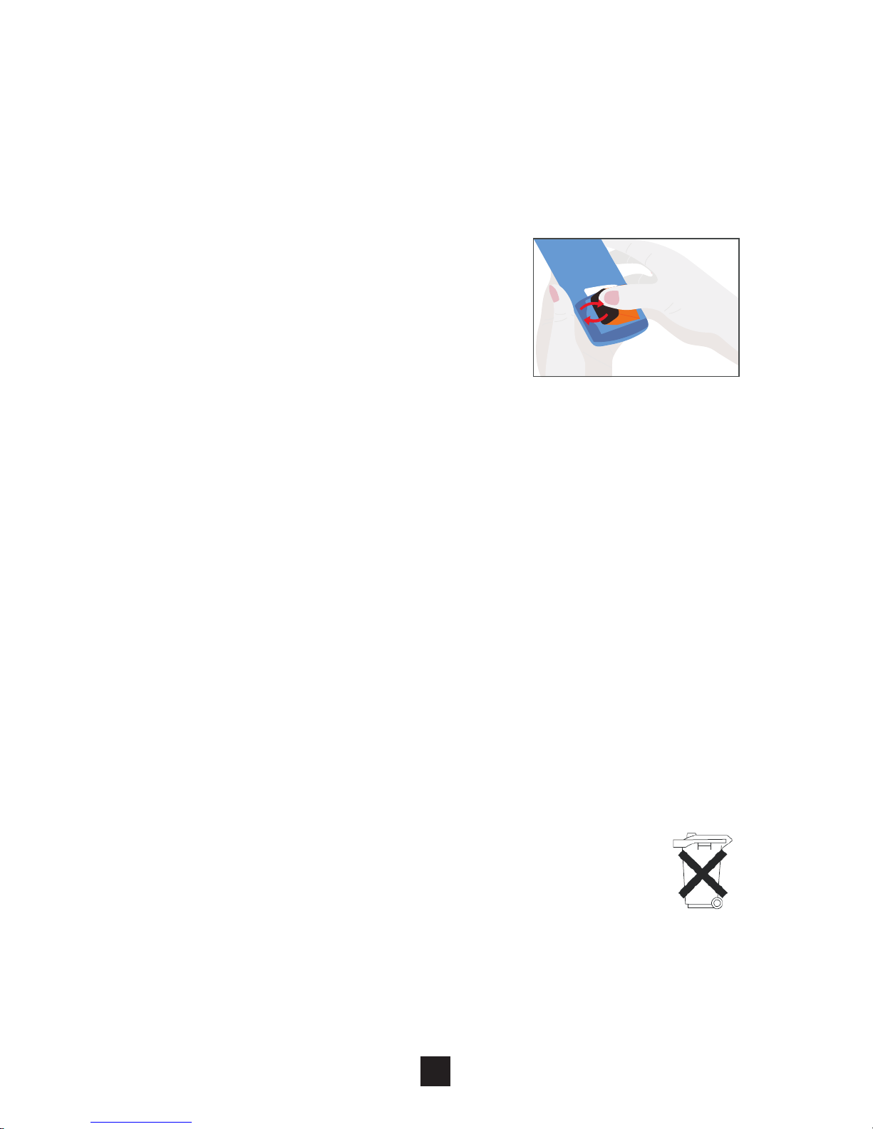
4.1.2 Disposal of battery
Spent batteries do not belong in the household
waste. Dispose of the battery according to the
current federal, state and local regulations. As
a consumer, you are obligated by law to return
spent battery.
23
4. Instruction for use
4 .1 Battery
4.1.1 Check/Replace the battery
Over time, in order to ensure the
functional safety of device,
changing the battery is necessary.
1) Slide the battery compartment
cover and open.
2) Insert the 9V battery into the
battery compartment.
3) Make sure you are installing the battery properly.
Be sure to match the positive and negative ends of
the battery to the marking in the battery
compartment of the device.
4) Press and pull down following the direction of the
arrow indicated on the photo.
5) Replace the battery compartment cover and press
to close.
6) If replace the battery, you should slide the battery
compartment cover and open. Pull up the battery
following the direction of the arrow indicated on the
photo. And insert the 9V battery according to the
above step 2) to 5).
Page 23
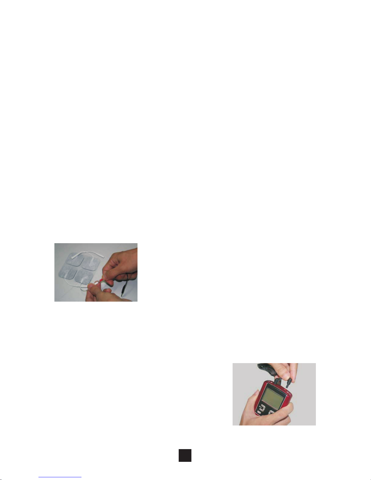
4.2 Connect electrodes to lead wires
Insert the lead wire connector into
electrodes connector (standard 0.08
inch female connection). Make sure no
bare metal of the pins is exposed.
Caution:
Always use the electrodes with the
requirements of the IEC/EN60601-1 ,
ISO10993-1/-5/-10 and IEC/
EN60601-1-2, such as with CE mark,
or which are legally marketed in the
US under 510(K) procedure.
24
Caution:
1) Battery may be fatal if swallowed. Therefore,
keep the battery and the product out of the
range of children, if a battery was swallowed,
consult a physician immediately.
2) If a battery has leaked, avoid contact with skin,
eyes and mucus membranes, Rinse the affected
spots with lots of clear water immediately and
contact a physician right away.
3) Battery may not be charged, dismantled, thrown
into fire or short-circuited.
4) Protect battery from excess heat; Take the
battery out of the product if they are spent or in
case you no longer use the article. This prevents
damage caused by leaking battery.
5) Always replace the same type battery.
4.3 Connect lead wires to device
1) Before proceeding to this step,
be sure the device is completely
turns OFF.
2) The wires provided with the
system insert into the jack
sockets located on top of the device.
Page 24
4.4 Electrode
4.4.1 Electrode options
The electrodes are disposable and should be
routinely replaced when they start to lose their
adhesive nature. If you are unsure of your electrode
adhesive properties, order replacement electrodes.
Replacement electrodes should be re-ordered
through or on the advice of your physician to ensure
proper quality. Follow application procedures
outlined in electrode packing, to maintain optimal
stimulation and to prevent skin irritation.
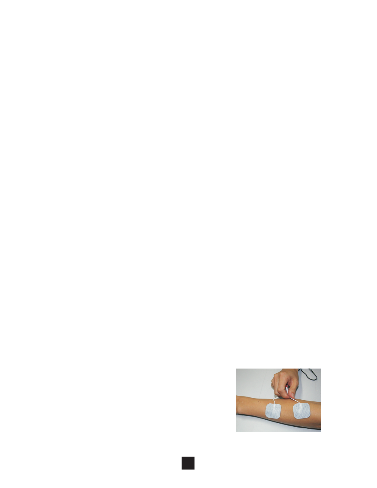
4.4.2 Place electrodes on skin
25
3) Holding the insulated portion of the connector, push
the plug end of the wire into one of the jacks (see
drawing); one or two sets of wires may be used.
4) This device has two output receptacles controlled
by Channel 1 and Channel 2 at the top of the unit.
You may choose to use one channel with one pair
of lead wires or both channels with two pairs of lead
wires. Using both channels gives the user the
advantage of stimulating two different areas at the
same time.
Caution:
Do not insert the plug of the patient lead wire into any AC
power supply socket.
Apply electrodes to the exact site
indicated by your physi cian or
t h e r a p i s t , b e f o r e a p p l y i n g
electrodes, be sure the skin surface
over which electrodes are placed is
thorou g h l y c l e a n ed a n d d r i e d .
Page 25

4.4.3 Electrode placement
The placement of electrodes can be one of the most
important parameters in achieving success with
therapy. Of utmost importance is the willingness of
the physician to try the various styles of electrode
placement to find which method best fits the needs of
the individual patient.
Every patient responds to electrical stimulation
differently and their needs may vary from the
conventional settings suggested here. If the initial
results are not positive, speak to your physician
ab o ut al t e rna t i ve st i mula t ion s e t tin g s a n d/or
e le ct r o d e p la c e m e n t s . O nc e a n a cc ep t a b l e
placement has been achieved, mark down the
electrodes sites and the settings, so the patient can
easily continue treatment at home.
26
Make sure the electrodes are placed firmly to the skin
and make good contact between the skin and the
electrodes. Place the electrodes over the skin; attach
them properly, firmly, and evenly.
Caution:
1) Before applying the self-adhesive electrodes, it
is recommended to wash and degrease the skin,
and then dry it.
2) Do not turns on the device when the self adhesive electrodes are not positioned on the
body.
3) Never remove the self-adhesive electrodes from
the skin while the device is still turns on.
4) It is recommended that, at minimum, 4cm*4cm
self-adhering based, square electrodes are used
at the treatment area.
Page 26
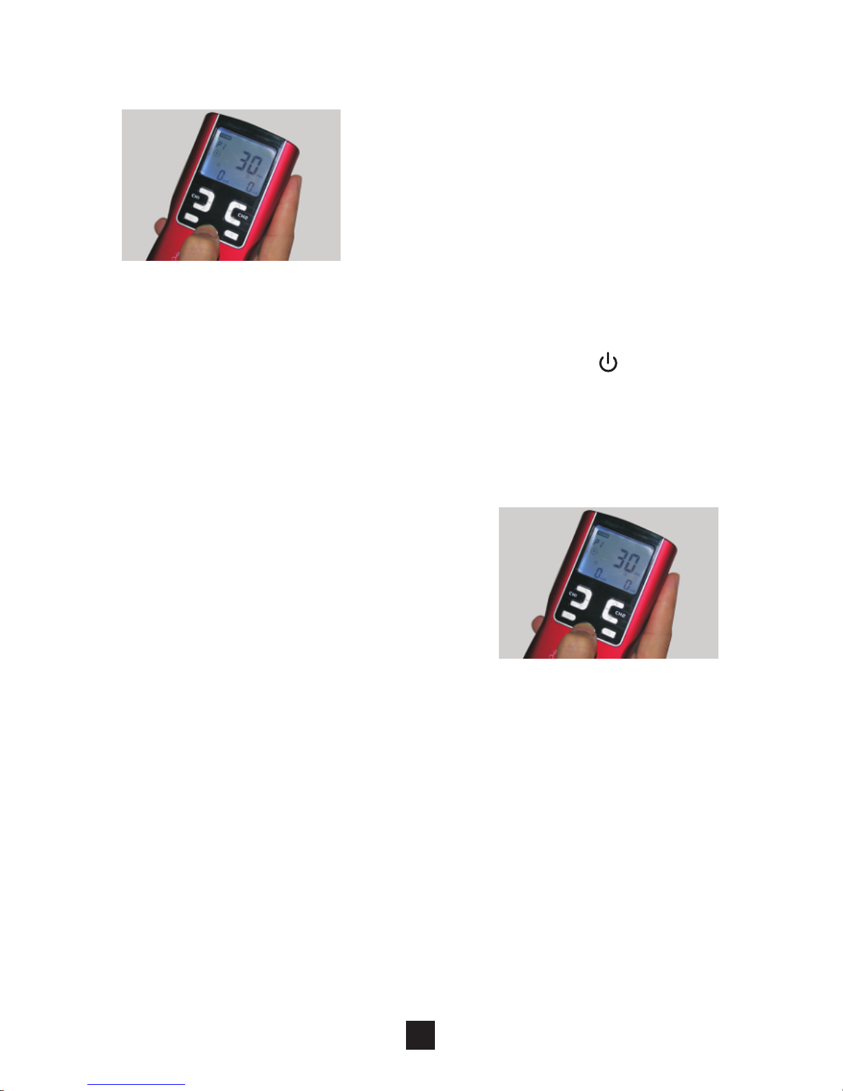
4.6 Select the Therapeutic Mode
There are 4 therapeutic modes
available –TENS, IF, MIC and
EMS. The therapeutic mode
can be selected by pressing
the [M] control.
Caution:
Consult your physician for your suitable
therapeutic mode
27
4.5 Turn on
Before using the device for the
first time, you are strongly
advised to take careful note of
the cou nter- indicatio ns an d
safety measures detailed at
the beginning of this manual
(Safety information), as this
powerful equipment is neither
a toy nor a gadget!
In order to turn on the device, keep the [ ] button
pressed down until the operation page appears on the
screen.
4.7 Steps to Set a New Program
4.7.1 TENS Setting
Press the [S] button cycle to enter the setting state.
The settings can be adjusted according to the
following steps:
Page 27
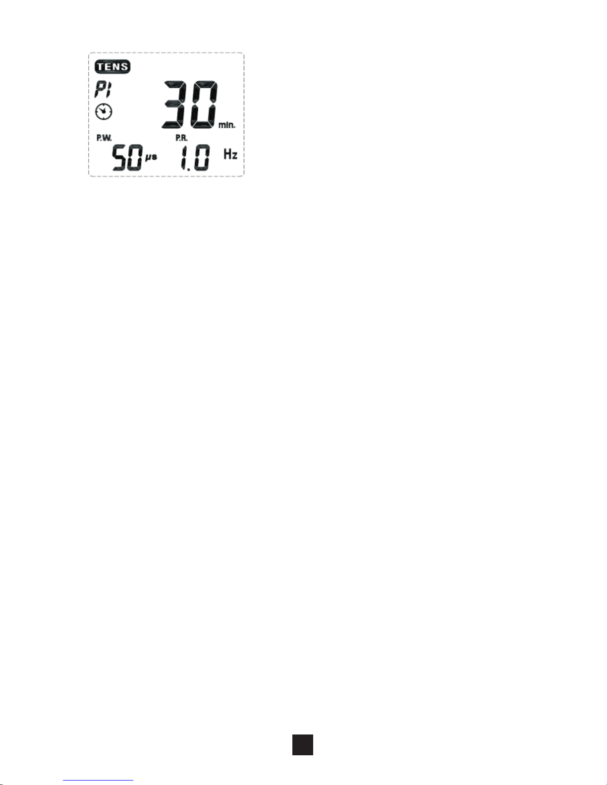
3) Set Timer
Press [S] button cycle to enter this setting. The
treatment time is adjustable from 1 to 60 minutes or
Continue. Press [▲ ] or [▼ ] button control to adjust
setting. You can set the timer to “Continuous” mode
by pressing the [▲] control when it shows 60 minutes.
Its output will be shut off when time is up.
4) Set Pulse Width
5) Set Pulse Rate
Pulse Width is adjustable from 50 uS to 300 uS. Press
[S] button to enter this menu, then press [▲ ] or [▼ ]
button to adjust the setting.
Pulse rate is adjustable from 1 Hz to 150 Hz (0, 5 Hz
to 5 Hz for Burst). Press [S] button cycle to enter this
menu, and then press [▲] or [▼] button to adjust the
setting.
28
1) Set the Therapeutic Program
2) Set Cycle Time (Optional)
There are 4 programs in TENS
therapeutic mode available –
Burst (P1), Normal (P2), Pulse
Width Modulation ( P 3), and
Pulse Rate Modulation (P4). The
ther a peutic progr a m can be
selected by pressing the [▲] and [▼ ] button. When
you choose to [B] program, program [B] outside of the
box will be flashing.
Cycle time is adjustable form 5 to 30 seconds. Only
modulation has this parameter setting. Press [S]
button cycle to enter this menu, and then press the
[▲] and[▼] button to adjusting the setting.
Page 28
2) Set Timer
Press [S] button cycle to enter this setting. The
treatment time is adjustable from 1 to 60 minutes or
Continue. Press [▲ ] or [▼] control to adjust setting.
You can set the timer to “Continuous” mode by
pressing the [▲] button when it shows 60 minutes. Its
output will be shut off when time is up.
Channel 1 has 4000 Hz fixed Fundamental frequency.
Channel has selectable frequency from 4001 to
4150 Hz; Interference frequency is adjustable form
2 Hz to 150 Hz. Only [P4] has this parameter setting.
Press [S] button cycle to enter this menu, and then
press the [▲] and [▼] button to adjusting the setting.
29
4.7.2 IF Setting
Press the [S] button to enter the setting state. The
settings can be adjusted according to the following
steps:
1) Set the Therapeutic Program
There are 4 programs in IF
therapeutic mode available. The
therap e u t i c program can be
selected by pressing the [▲] and
[▼ ] bu t t o n . T h e m o d e y o u
selected will show up on the top
of liquid crystal display.
3) Set Interference frequency (optional)
Page 29
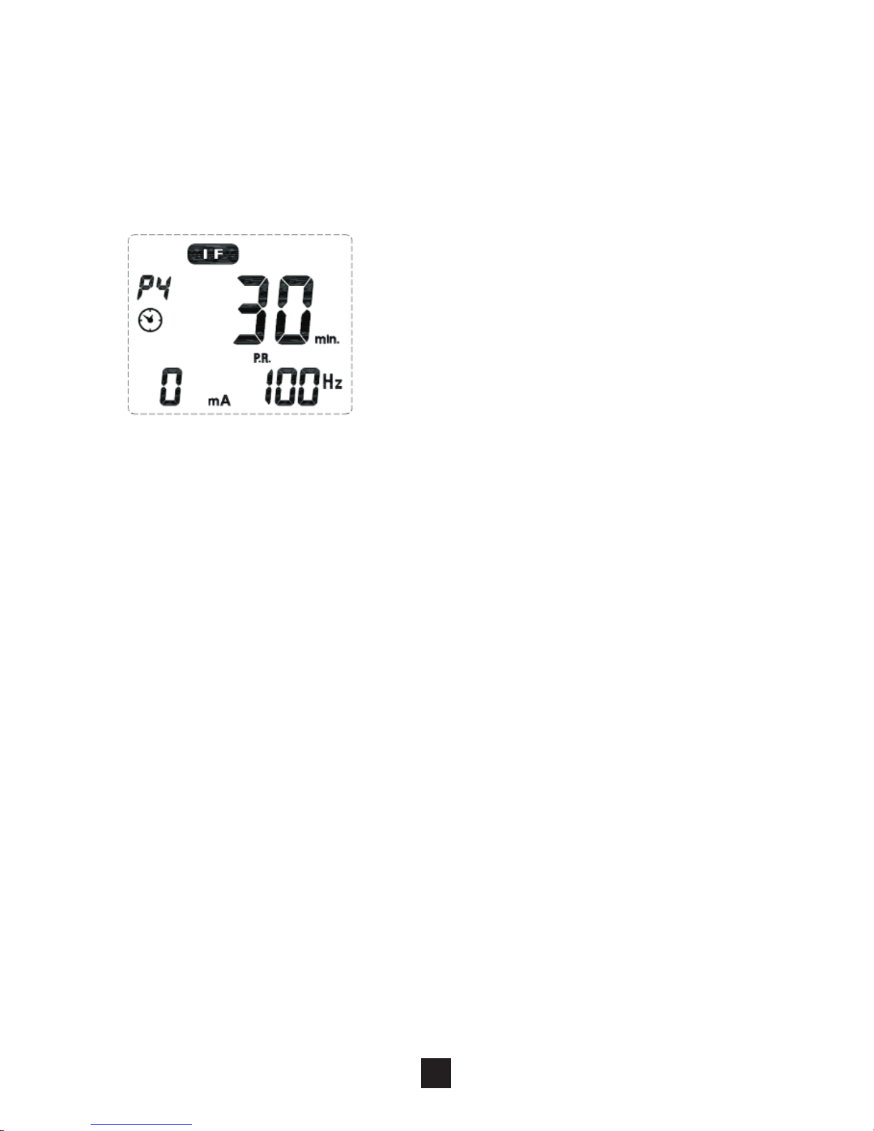
The therapeutic program can be selected by pressing
the [▲ ] and [▼ ] button. The mode you selected will
show up on the top of liquid crystal display.
Press [S] button cycle to enter this setting. The
treatment time is adjustable from 1 to 60 minutes or
Continue. Press [▲ or [▼ button control to adjust
setting. You can set the timer to “Continuous” mode
by pressing the[▲] control when it shows 60 minutes.
Its output will be shut off when time is up.
] ]
2) Set Timer
3)Set Pulse Width
Pulse Width is adjustable from 2ms to200ms. Press
[S] button cycle to enter this menu, then press [▲] or
[▼] button to adjust the setting.
30
Cycle time is adjustable form 5
to 30 seconds. Press [S] button
cycle to enter this menu, and
then press the [▲ and [▼
button to adjusting the setting.
] ]
4) Set Cycle Timer
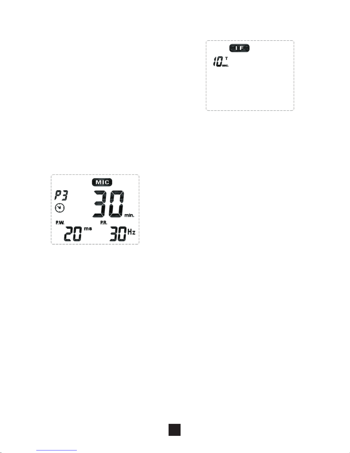
4.7.3 MICROCURRENT Setting
Press the [S] button cycle to enter the setting state.
The settings can be adjusted according to the
following steps:
1) Set the Therapeutic Program
There are 3 programs in MIC
therapeutic program available –
Co n sta n t ( P 1), P u lse W i dth
Modulation (P2), and Pulse Rate
Modulation (P3).
Page 30
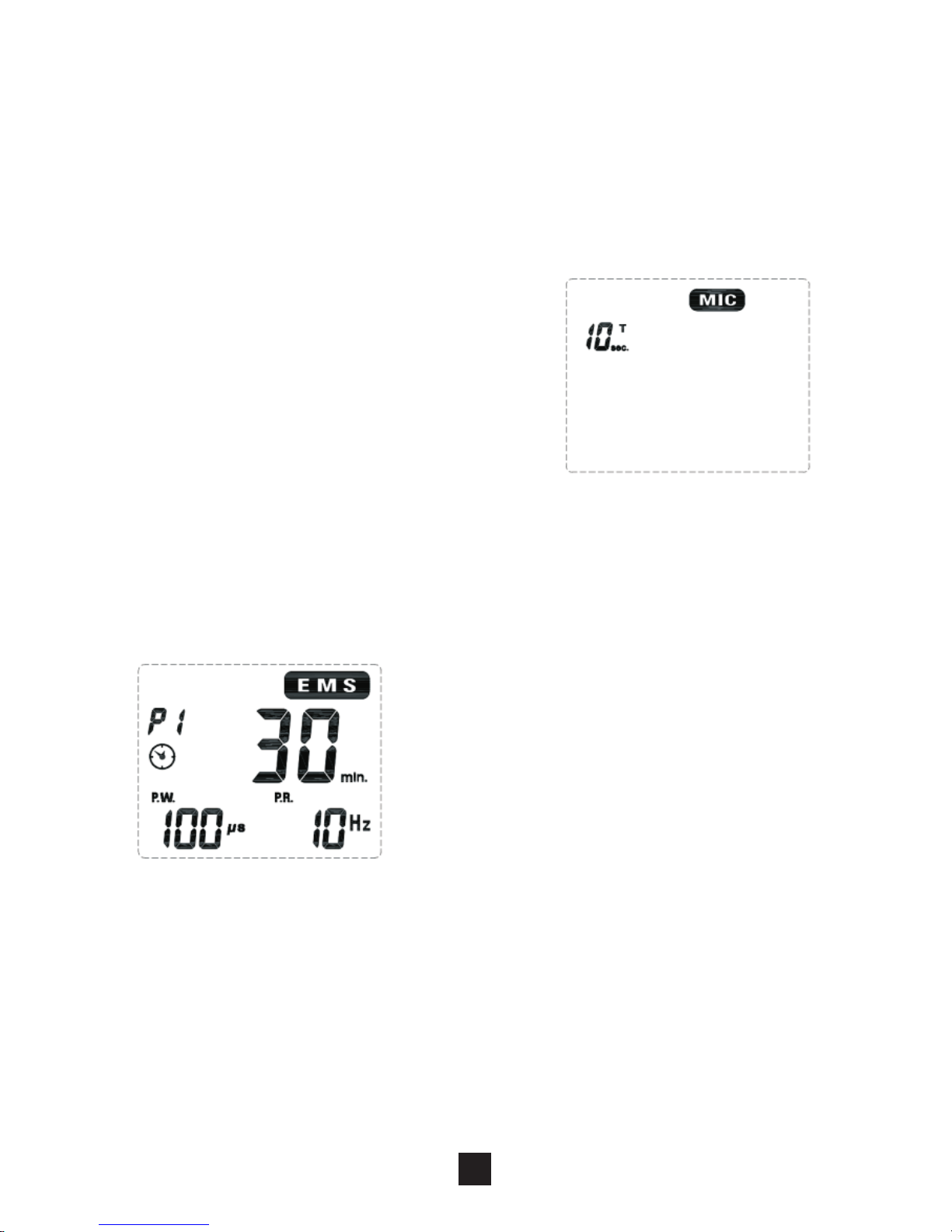
4.7.4 EMS Setting
Press the [S] button cycle to enter the setting state.
The settings can be adjusted according to the
following steps:
1) Set the Therapeutic Program
There are 3 programs in EMS
t h er ap e ut ic m od e a v ai l a b le
–Delay (P1), Synchronous (P2)
a n d A l t e r n a t e ( P 3 ) . T h e
therapeutic program can be
selected by pressing the [▲ and]
[▼ ] button. When you choose to [S] program,
program [S] outside of the box will be flashing.
31
Pulse rate is adjustable from 1 Hz to 150 Hz. Press
[S] button cycle to enter this menu, and then press [▲]
or [▼] button to adjust the setting.
4) Set Pulse Rate
5) Set Cycle Time (Optional)
Cycle time is adjustable form 5
to 30 seconds. Only modulation
m o d e h a s t h i s p a r a m e t e r
setting. Press [S] button cycle
to enter this menu, and then
press the [▲ and [▼ button to
adjusting the setting.
] ]
2) Set Timer
Press [S] button cycle to enter this setting. The
treatment time is adjustable from 1 to 60 minutes or
Continue. Press [▲] or [▼] control to adjust setting.
You can set the timer to “Continuous” mode by
Page 31

5) Set Delay Time(Optional)
Delay time is adjustable form 1 to 10 seconds. Only
Delay therapeutic program ha s this parameter
setting. Press [S] button cycle to enter this menu, and
then press the [▲ ] and [▼ ]button to adjusting the
setting.
The ramp time controls the time of output current that
increase from 0 to the setting level, and from the
setting value to 0. When the ramp time is set, each
contraction may be ramped up and down in order that
the signals come on and come off gradually and
smoothly. The ramp time is adjustable from 1 to 6
seconds.
6) Set Ramp Time
32
pressing the [▲ ] button when it shows 60 minutes.
Its output will be shut off when time is up.
3) Set Pulse Width
The pulse width determines the length of time. Each
electrical signal is applied through the skin, which
c o nt ro l s t h e s tr e ng th a nd s en sa t io n o f th e
stimulation. Press [S] button cycle to enter this
setting. The pulse width is adjustable from 50 to 300
uS.Press [▲] or [▼] button to adjust the setting.
The pulse rate determines how many electrical
impulses are applied through the skin each second.
Press [S] button cycle to enter this menu. By
the [▲ ] or [▼ ] button to adjusting the setting. The
pulse rate is adjustable from 1 Hz to 150 Hz.
4) Set Pulse Rate
Page 32
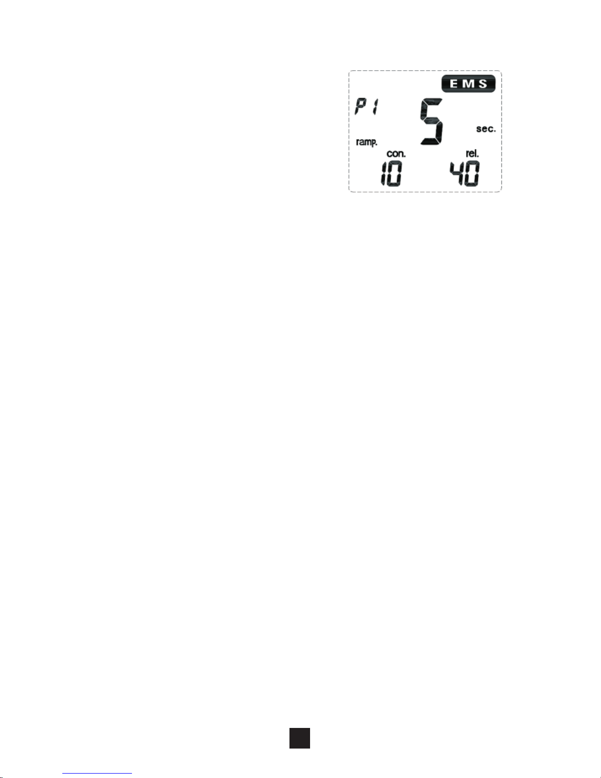
8) Set Relaxation (OFF) time
The Off Time controls the time of relaxation. The
relaxation time can be adjusted. Press [S] button
cycle to enter this menu, and then press the [▲] and
[▼ ] button to adjusting the setting. Both channels'
stimulation is cycled on and off by the contraction and
relaxation settings. The range is adjustable from 0 to
60 seconds.In Alternate program, the OFF Time
should be equal or more than the ON Time. (OFF
TIME ≥ON TIME)
Press the intensity control button ([▲ ] and [▼ ] ) to
control the intensity output. Slowly press the intensity
b u t t on c on t r o l u n ti l y o u r e a c h t h e s e t t i n g
recommended by your physician or therapist. Repeat
for the other channel, if both channels are to be used.
4.8 Adjust Channel Intensity
33
The contract Time controls the
t i me o f st im u la t io n. Th e
c o n t r a c t i o n t i m e c a n b e
adjusted. Press [S] button
cycle to enter this menu, and
then press the [▲ ] and [▼ ]
button to adjusting the setting.
Both channels’ stimulation is cycled on and off by the
contraction and relaxation settings. The range is
adjustable from 1 to 30 seconds.
7) Set Contract Time
Caution:
Contract time has not including the ramp up and
ramp down time, ON time=Ramp up + Contract time
+ Ramp down.
Page 33

4.9. Lock the button
The Safety Lock Feature automatically activates after
there is no operation in the panel for 30 seconds by
locking out the ability to press the buttons. This is a
safety feature to prevent accidental changes to your
settings and to prevent accidental increases to the
intensity levels. You can press either one of the [▼ ]
buttons to unlock the device.
4.10. Stop the treatment
When you have activated the treatment timer, you can
press the [M] button or the [ ▼ ] button to control stop
the treatment.
Caution:
Default state, if the button is locked, you can
press only one of the [ ▼ ]buttons to unlock, and
then press the [M] button or the [▼ ] button to
control stop the treatment.
4.11. Turn OFF
Press [ ] button and hold for approx.3 seconds to
Turn OFF the device.
34
If the stimulation levels are uncomfortable or
become uncomfortable, reduce the stimulation
intensity to a comfortable level and contact
your medical practitioner if problems persist.
TENS, EMS and IF therapeutic mode. If the
electrodes no placed firmly on skin or the
device has not connected on the electrodes,
the stimulator's output intensity surpasses
12mA, the intensity will enulls automatically.
Caution:
1)
2)
Page 34

4.12. Low battery indicator
When the low power indicator flashes, the device will
be turns off automatically, the battery should be
replaced with a new one as soon as possible.
However, the unit may continue to operate for a few
more hours depends on the setting intensity level.
35
Caution:
If there is no operation in the panel for 3
minutes in the waiting state, the device will be
turns off automatically.
In shutdown state, keep pressing the channel 2
[ ▼ first, and then press [ ]button at the same
to restore factory parameter settings
]
1)
2)
Page 35

5. Program
Mode Program
Modulation
Method
Frequency
Pulse
Width
Treat time
TENS
P1
Burst
0.5-5Hz
50-300us
1-60min,continous
P2
Continuous
1-150Hz
50-300us
1-60min,continous
P3
Pulse width
modulation
1-150Hz
50-300us 1-60min,continous
P4
Frequency
modulation
1-150Hz
50-300us 1-60min,continous
EMS
P1
Synchronous
1-150Hz
50-300us 1-60min,continous
P2
Asynchronous
1-150Hz
50-300us 1-60min,continous
P3
Delay
1-150Hz
50-300us 1-60min,continous
IF
P1
Frequency
modulation
4kHz
4001-4010Hz
125us 1-60min,continous
P2
Frequency
modulation
4kHz
4001-4150Hz
125us 1-60min,continous
P3
Frequency
modulation
4kHz
4080-4150Hz
125us 1-60min,continous
P4
Frequency
modulation
4kHz
4001-4150Hz
125us 1-60min,continous
MIC
P1
Continuous
1-150Hz
2-200ms 1-60min,continous
P2
Pulse width
modulation
1-150Hz
2-200ms
1-60min,continous
P3
Frequency
modulation
1-150Hz 2-200ms 1-60min,continous
36
Page 36

6. Cleaning and Care
6.1 Tips for skin care
To avoid skin irritation, especially if you have sensitive
skin, follow these suggestions:
1) Wash the area of skin where you will be placing the
electrodes, using mild soap and water before
applying electrodes, and after taking them off. Be
sure to rinse soap off thoroughly and dry skin well.
2) Excess hair may be clipped with scissors; do not
shave stimulation area.
3) Wipe the area with the skin preparation your
clinician has recommended. Let this dry. Apply
electrodes as directed.
4) Many skin problems arise from the “pulling stress”
from adhesive patches that are excessively
stretched across the skin during application. To
prevent this, apply electrodes from centre outward;
avoid stretching over the skin.
5) To minimize “pulling stress”, tape extra lengths of
lead wires to the skin in a loop to prevent tugging on
electrodes.
6) When removing electrodes, always remove by
pulling in the direction of hair growth.
7) It may be helpful to rub skin lotion on electrode
placement area when not wearing electrodes.
8) Never apply electrodes over irritated or broken skin.
37
Page 37
6.2 Cleaning the device
1) Remove the battery from the device every time
when you clean.
2) Clean the device after use with a soft, slight
moistened cloth. In case of more extreme soiling
you can also moisten the cloth with mild soapy
water.
3) Do not use any chemical cleaners or abrasive
agents for cleaning.
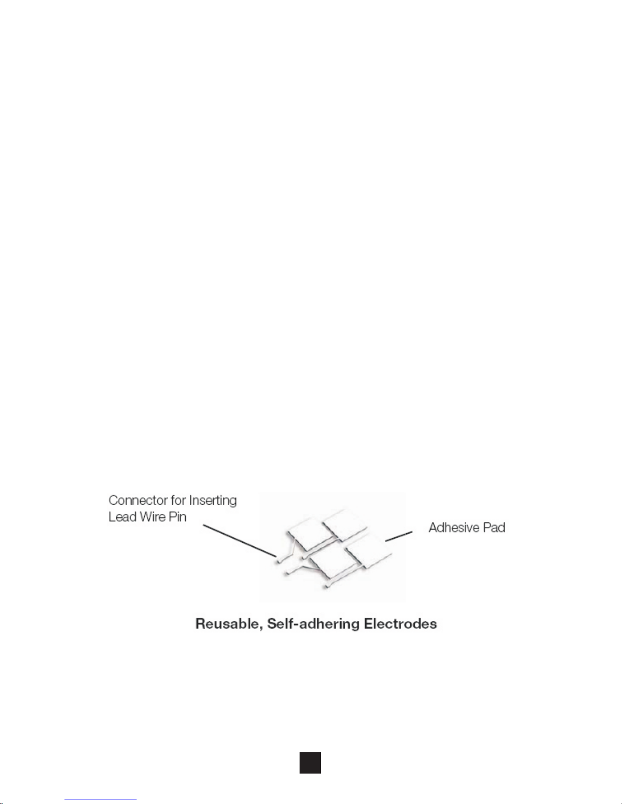
6.3 electrodes
1) Use the device only with the leads and electrodes
provided by the manufacturer. Use only the
electrode placements and stimulation settings
prescribed by your physician or therapist.
2) It is recommended that, at minimum, 4cm*4cm self
-adhering based, square electrodes are used at the
treatment area.
3) Inspect your electrodes before every use. Replace
electrodes as needed. Reusable electrodes may
cause slight skin irritation, lose adhesion and
deliver less stimulation if overused.
38
Page 38

To use these electrodes:
1) Attach the electrode to the lead wire.
2) Remove the protective backing from the electrode
surface. Do not throw away the protective backing
because it is reused after the treatment session
has been completed.
3) Place the tacky surface to the prescribed skin area
by pressing the electrode firmly against the skin.
To remove your electrodes:
1) Lift the corner of the electrode and gently remove it
from the skin.
2) Apply the protective backing to the tacky side of the
electrode. Place the electrode on the side of the
protective backing that is labeled with the word on.
3) It may be helpful to improve repeated application
by spreading a few drops of cold water over the
adhesive and turn the surface up to air dry. Over
Saturation with water will reduce the adhesive
properties.
4) Between uses, store the electrodes in the
resealable bag in a cool dry place.
Caution:
Do not pull on the electrode wire. Doing so may
damage the wire and electrode.
Do not apply to broken skin.
The electrodes should be discarded when they
are no longer adhering.
The electrodes are intended for single patient
use only.
If irritation occurs, discontinue use and consult
your clinician.
Read the instructions for use of self-adhesive
electrodes before application.
39
Page 39

Always use the electrodes with the requirements
of the IEC/EN60601-1, ISO10993-1/-5/-10 and I
EC/ EN60601-1-2, such as with CE mark, or are
legally marketed in the US under 510(K)
procedure.
6.4 Cleaning the Electrodes cords
Clean the electrode cords by wiping them with damp
cloth. Coating them lightly with talcum powder will
reduce tangles and prolong the life.
6.5 Maintenance
1) Maintenance and all repairs should only be carried
out by an authorized agency. The manufacturer will
not be held responsible for the results of
maintenance or repairs by unauthorized persons.
2) The user must not attempt any repairs to the device
or any of its accessories. Please contact the
retailer for repair.
3) Opening of the equipment by unauthorized
agencies is not allowed and will terminate any
claim to warranty.
4) Check the unit before each use for signs of wear
and/or damage. Replace wear items as required.
40
Page 40

7. Troubleshooting
If your device does not seem to be operating correctly,
refer to the chart below to determine what may be
wrong. Should none of these measures correct the
problem, the device should be serviced.
41
Problem
Possible Cause Solution
Displays fail
to light up
Battery
contact failure
1. Try fresh batteries.
2. Ensure batteries are
inserted correctly. Check
the following
contacts:
All contacts are in place.
All contacts are not broken.
Stimulation
weak
Electrodes
1. Dried out or
contaminated
2. Placement
Lead wires
1.Old/worn/
damaged
Replace and re-connect
Replace
Stimulation
is
uncomfortable.
Intensity is too
high
Electrodes are
too close
together
Damaged
or worn
electrodes or
lead wires
Electrode active
area size is too
small.
Decrease intensity.
Reposition the electrodes.
Replace.
Replace electrodes with
ones that have an active
area no less than 16.0cm
2(4cm*4cm).
Page 41

42
Intermittent
output
Lead wires
Program option
in use
1. Verify connection is
secure. Insure firmly.
2. Turn down the intensity.
Rotate lead wires in socket
90°. If still intermittent,
replace lead wire.
3. If still intermittent after
replacing lead wire, a
component may have failed.
Call the repair department.
Some programs will seem
intermittent. This is
expected. Refer to the
Program Option Controls
in the Operation section for
a description of the
program option.
Stimulation
is
ineffective.
Improper
electrode and
applicator
placement
Unknown
Reposition electrode
and applicator
Contact clinician.
8. Storage
1) For a prolonged pause in treatment, store the
device in a dry room and protect it against heat,
sunshine and moisture.
2) Store the device in a cool, well-ventilated place
3) Never place any heavy objects on the device.
Page 42
9. Disposal
Used fully discharged batteries must be disposed of in
a specially labeled collection container, at toxic waste
collection points or through an electrical retailer. You
are under legal obligation to dispose of batteries
correctly.
Please dispose of the device in
accordance with the legal obligation.
10. Electromagnetic Compatibility (EMC) Tables
Guidance and manufacturer's declaration
- electromagnetic emissions
The device is intended for use in the electromagnetic
environment specified below. The customer or the user
assures that it is used in such an environment.
Emissions
test
Compliance
Electromagnetic environment
- guidance
RF
emissions
CISPR 11
Group 1
The device uses RF energy only
for its internal function. Therefore,
its RF emissions are very low and
are not likely to cause any
interference in nearby electronic
equipment.
43
Page 43
RF
emissions
CISPR11
Class B
Harmonic
emissions
lEC
61000-3-2
Not
applicable
Voltage
fluctuations
/flicker
emissions
lEC
61000-3-3
Not
applicable
The device is suitable for use in
all establishments other than
domestic and those directly
connected to the public lowvoltage power supply network
that supplies buildings used for
domestic purposes.
44
Guidance and manufacturer's declaration —
electromagnetic immunity
The device is intended for use in the electromagnetic
environment specified below. The customer or the user
should assure that it is used in such an environment.
Immunity
test
IEC 60601
test level
Electrostatic
discharge
(ESD) EC
61000-4-2
±
contact
±8 kV air
6 kV
Compliance
level
Electromagnetic
environment guidance
±
contact
±8 kV air
6 kV
Floors should be
wood, concrete or
ceramic tile. If floors
are covered with
synthetic material,
therelative humidity
should be at least
30 %.
Page 44
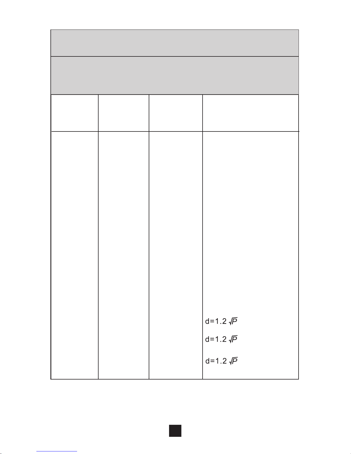
Guidance and- manufacturer's declaration.
Electromagnetic immunity
The device is intended for use in. the electromagnetic
environment specified below. The customer or the user
should assure that it is used in such an environment.
Emissions
test
IEC 60501
test level
Compliance
level
Conducted
RF lEC
61000-4-6
Radiated
RF lEC
61000-4-3
3 Vrms
150 kHz
to 80 MHz
3 V/m80
MHz to
2.5 GHz
3 Vrms
3 V/m
Portable and mobile
RF communications
equipment should
be used no closer to
any part of the device,
including cables,
than the
recommended
separation distance
calculatedfrom the
equation applicable
to the frequency of
the transmitter.
Recommended
separation
distance
Electromagnetic
environment guidance
, 80MHz
to 800MHz
, 800MHz
to 2,5MHz
45
Page 45
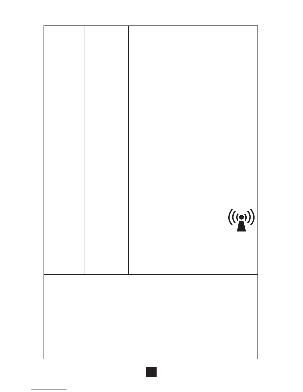
Where P is the
maximum output
power rating of the
transmitter In watts
(W) according to the.
Transmitter
manufacturer and
d Is the recommended
separation distance
in meters (m).
Field strengths from
fixed RF transmitters,
as determined by an
electromagnetic site
survey, should be
less than the
compliance level
in each frequency
range.
Interference
may occur In
the vicinity of
equipment marked
with the following
symbol:
NOTE I At 80 MHz ends 800 MHz. the higher frequency
range applies.
NOTE 2 These guidelines may not apply in all situations.
Electromagnetic propagation is affected by absorption
and reflection from structures, objects and people.
1. Field strengths from fixed transmitters, such as base
stations for radio (cellular/cordless) telephones and
land mobile radios, amateur radio, AM and FM radio
broadcast and TV broadcast cannot be predicted
46
Page 46
theoretically with accuracy. To assess the
electromagnetic environment due to fixed RF
transmitters, an electromagnetic site survey should be
considered. If the measured field strength in the
location in which the device is used exceeds the
applicable RF compliance level above, should be
observed to verify normal operation. If abnormal
performance is observed, additional measures may
be necessary, such as reorienting or relocating the
device.
2.Over the frequency range 150 kHz to 80 MHz, field
strengths should be less than [Vi] V/m.
47
Rated
maximum
output
power of
transmitter
W
Separation distance according to frequency
of transmitter
150 kHz
to 80 MHz
Recommended separation distances between
portable and mobile RF communications equipment
and the device
The device is intended for use in an electromagnetic
environment in which radiated RF disturbances are
controlled. The customer or the user of the device can
he l p p r ev e nt e l e ct r om a gn e ti c i n te r fe r en c e b y
maintaining a minimum distance between portable
a n d m o b i l e R F c o m m u n i c a t i o n s e q u i p m e n t
(t ransmit te rs) an d th e a s r ecommen ded be low,
according to the maximum output power of the
communications equipment.
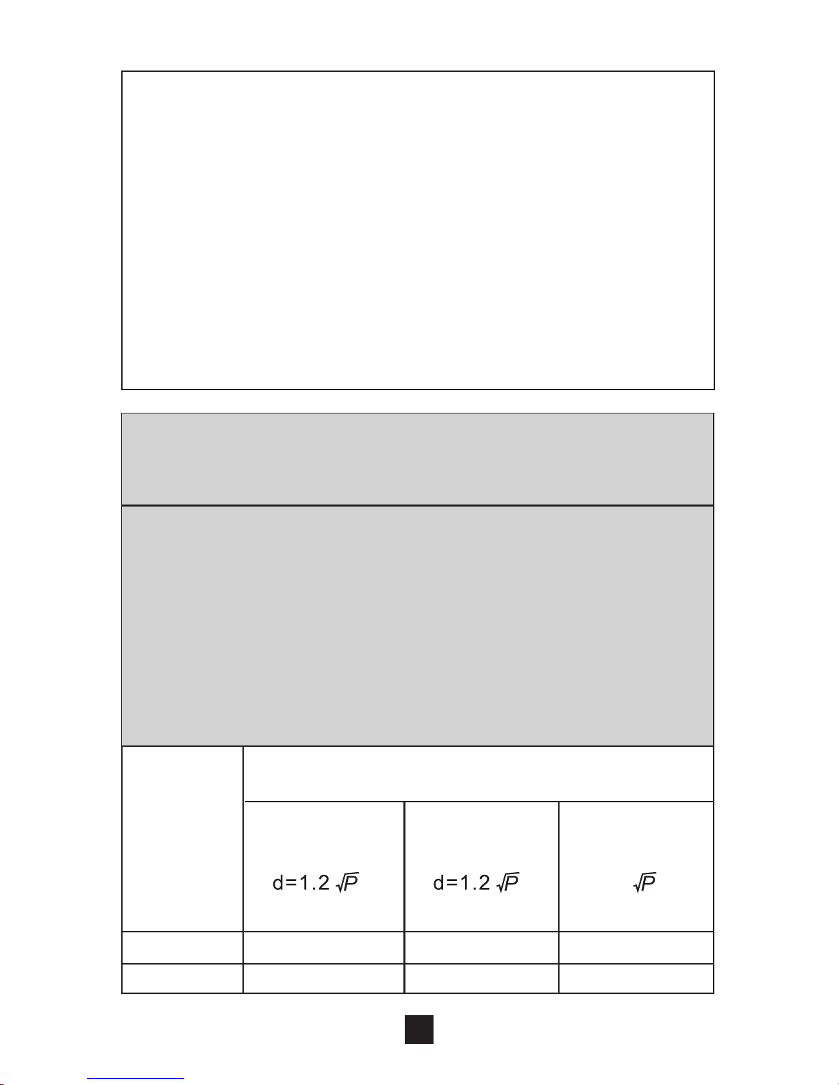
d=2.3
80 MHz
to 800 MHz
800 MHz
to 2,5 GHz
0.01 0.12 0.12
0.23
0.1
0.38 0.38 0.73
Page 47
1 1.2 1.2
2.3
10
3.8 3.8 7.3
100
12 12
23
For transmitters rated at a maximum output power not
listed above, the recommended separation distance d in
meters (m) can be estimated using the equation applicable
to the frequency of the transmitter, where P is the
maximum output power rating of the transmitter in watts
(W) accordable to the transmitter manufacturer.
NOTE I At 80 MHz and 800 MHz. the separation distance
for the higher frequency range applies.
NOTE 2 These guidelines may not apply in all situations.
Electromagnetic propagation is affected by absorption
and reflection from structures, objects and people.
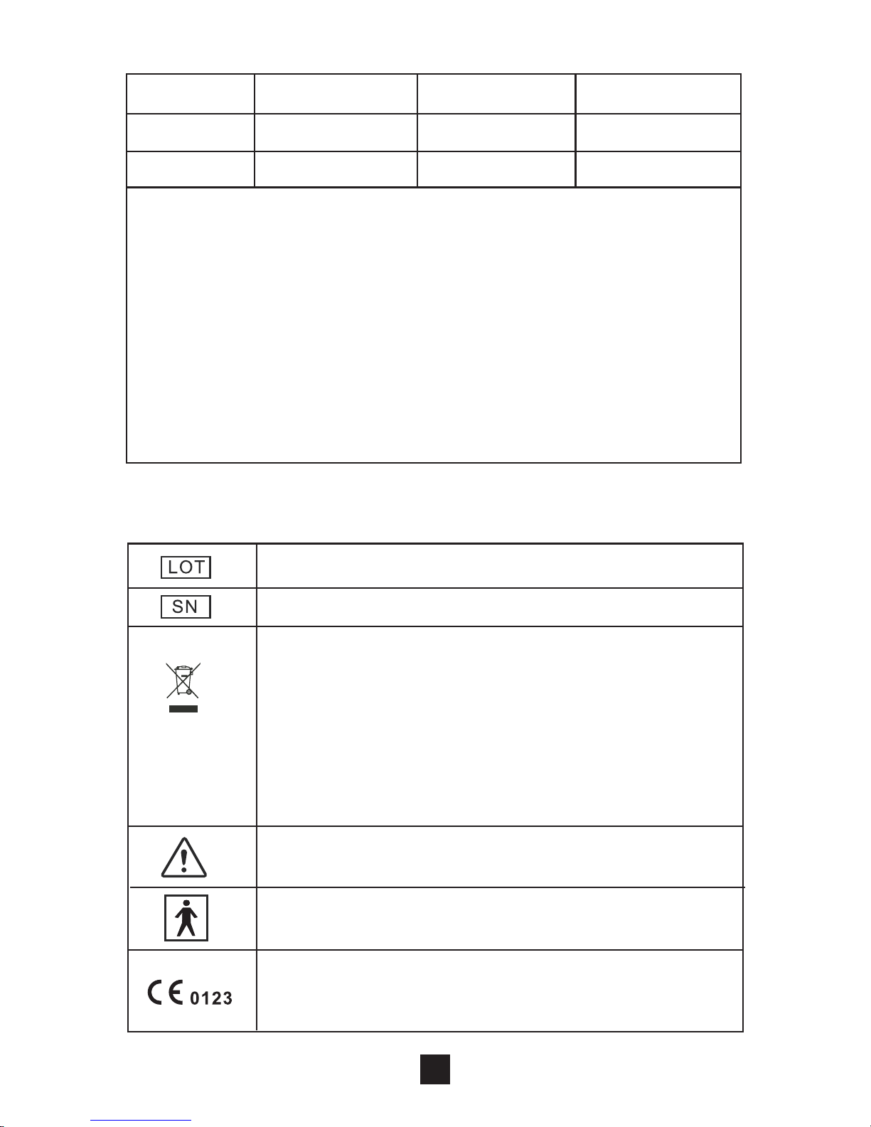
11. Glossary of Symbols
Batch code
Electrical devices are recyclable material and
should not be disposed of with household
waste after their useful life! Help us to protect
the environment and save resources and take
this device to the appropriate collection points.
Please contact the organization which is
responsible for waste disposal in your area
if you have any questions.
Serial number
Attention: Read the operating instruction
for use!
Degree of Electrical Protection BF
Complies with MDD 93/42/EEC and amended
by directive 2007/47/EC requirements,
Notified body TUV SUD (0123)
48
Page 48

12. Warranty
Please contact your dealer or the device centre in
case of a claim under the warranty. If you have to send
in the unit, enclose a copy of your receipt and state
what the defect is.
The following warranty terms apply:
1) The warranty period for device is one years from
date of purchase. In case of a warranty claim, the
date of purchase has to be proven by means of the
sales receipt or invoice.
2) Repairs under warranty do not extend the warranty
period either for the device or for the replacement
parts.
3) The following is excluded under the warranty:
All damage which has arisen due to improper
treatment, e.g. nonobservance of the user
instruction.
All damage which is due to repairs or tampering
by the customer or unauthorized third parities.
49
Damage which has arisen during transport from
the manufacturer to the consumer or during
transport to the service centre.
Accessories which are subject to normal wear
and tear.
4) Liability for direct or indirect consequential losses
caused by the unit is excluded even if the damage
to the unit is accepted as a warranty claim.
Page 49
Allied Health Medical Supplies.
152A Gaffney St Coburg
VIC 3058 Australia
Made in China
PRODUCT CODE: MT8000
Tel: 03 9366 6611
www.physipod.com.au
Manufactured For:
 Loading...