

Page 1
Quick Install Guide
Network Infrastructure
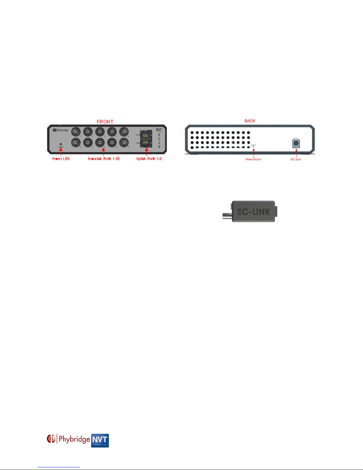
BNC Port
Ethernet Side
RJ45 Port
EC-Link
CLEER Switch - Model EC10
Beyond PoE: Delivering Power over Long Reach Ethernet
The CLEER (Coax Leveraged Ethernet Extended Reach) family of data switches delivers Ethernet and Power
over Ethernet over Coax cable with multiple times the reach of traditional data switches. With the EC10 switch
customers can transform their existing Coax infrastructure for IP camera deployment. For complete details refer
to the Hardware Installation Guide at www.phybridge.com
EC10 Switch
EC10 Switch Package Includes:
1. 1 x EC10 unit
2. 1 x AC/DC Power Adapter
3. Quick Install Guide
EC-Link Package Includes:
4. 2 x EC-Links
Installation Considerations
Location Requirements
Power - The AC/DC Power Adapter must be placed within 6 feet of an available power source.
Ventilation - To ensure proper ventilation of the EC10, leave at least 2 inches of unobstructed space on
all sides of the unit.
Downlink – The EC-Link adapters should be installed a minimum of 6 feet away from the EC10 switch.
Installation procedures will be trouble‐free if you ensure that the following items are available
before you begin:
• The CLEER switch model EC10, and all cables and accessories you received in the EC10 package.
• All EC-Link Adapters required for connecting the IP endpoint devices.
• Standard CAT5e copper LAN cables for the uplink trunks (user‐supplied).
• Coax cable for the downlink ports (user-supplied).
EC 10 – Quick Install Guide 1
Page 2
Hardware Topology and Installation Overview
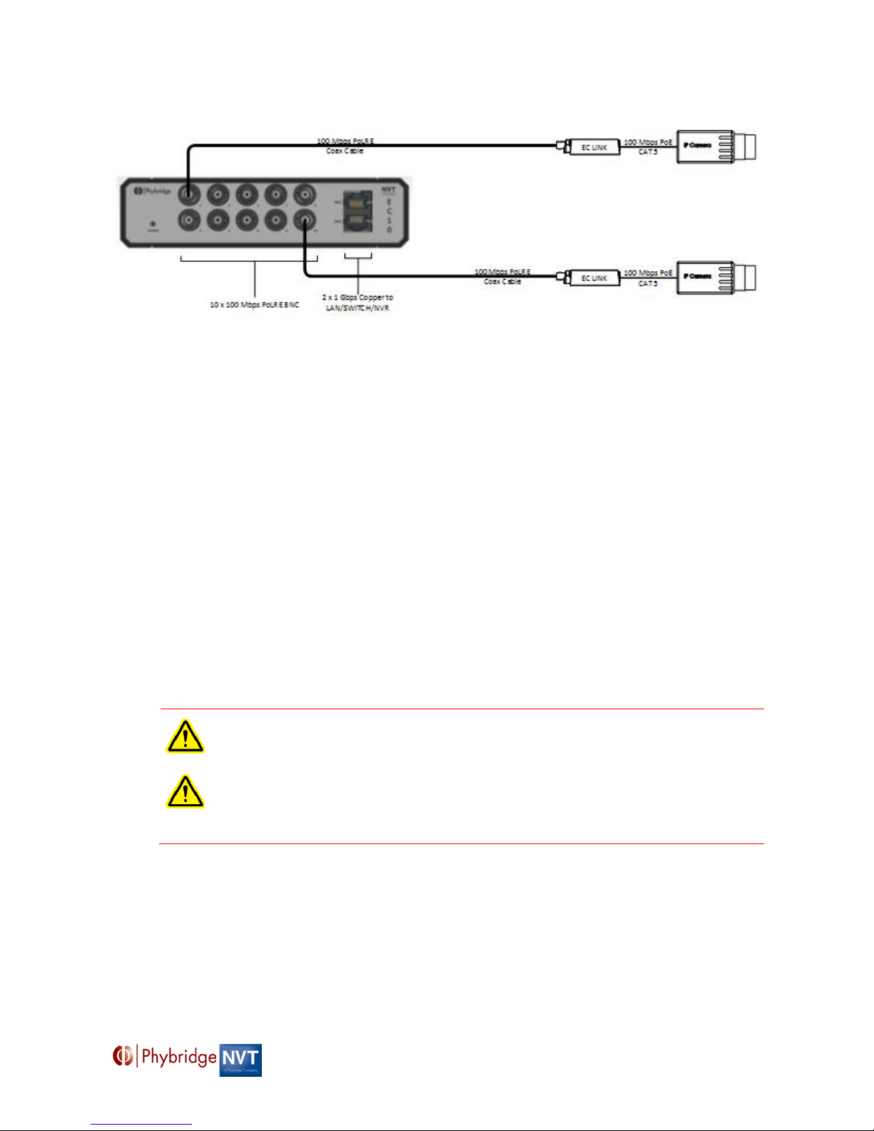
1. Remove the EC10 switch and all acc omp any ing accessories.
2. Remove all legacy cameras from the Coax cable.
Note: It is extremely important that non-IP, non-PoE cameras are not connected when you power on
the EC10.
3. Connect an EC-Link to the Network jack on the IP endpoint and connect the BNC Jack on the EC-
Link to one end of the Coax cable.
4. Connect the other end of the Coax cable to BNC connectors on the EC10 switch.
5. Connect the uplink cable from a Gigabit port to the IP PBX or network switch.
Note: This connection also permits inband management over Ethernet.
6. Power up the EC10.
7. For troubleshooting, please refer to the Hardware Installation Guide located at www.phybridge.com.
8. To reset the unit, press the reset button.
Note the following:
All of the above instructions provide basic installation information, necessary for the proper and safe
functioning of this equipment. Persons installing or maintaining this product must read all of the safety
instructions and the parts of system grounding which are applicable to the system being maintained.
Only trained, qualified service personnel shall install or maintain this product.
WARNING: FAILURE TO FOLLOW ALL INSTRUCTIONS MAY RESULT IN IMPROPER
EQUIPMENT OPERATION AND/OR RISK OF ELECTRICAL SHOCK.
WARNING: ANY CONNECTION TO AN OUTSIDE PLANT LEAD, AN OFF-PREMISE
APPLICATION, OR ANY OTHER EXPOSED PLANT APP LICATI ON MAY RESULT IN A
FIRE OR SHOCK HAZARD, AND/OR DEFECTIVE OPERATION, AND/OR EQUIPMENT
DAMAGE.
• Keep these instructions with the equipment.
• Do not attempt to install or service this equipment unless you are skilled in the installation and
maintenance of electronic telecommunications equipment and have successfully completed specific
training for this equipment.
EC 10 – Quick Install Guide 2
Page 3

Access to the interior of this unit
Der Zugang i ns Innere des
Seul un spécialiste doit av oir
El servici o de antenimiento y
autorizados por el fabricante.
To ensure ade quate cooling of the
Um die Kühlun g des Gerätes ni cht
Geräts vorhanden.
Afin de ne pas nuire au proc essus
l'appareil.
Para garantizar una refrigeración
To prevent the risk of shock or fire
Zur Vermeid ung der
Afin d’éviter tout risque d’ incendie
Para su propia protección,
Technical Support
The Phybridge Technical Support Group is available to assist you with product installation,
configuration, monitoring and troubleshooting procedures. Should you experience trouble with this
equipment or for repair or warranty information, go to www.phybridge.com
information or email [email protected].
The NVT Technical Support Group is available to assist you with product installation,
configuration, monitoring and troubleshooting procedures. Should you experience trouble with this
equipment or for repair or warranty information, go to www.nvt.com
or email [email protected].
Safety Warnings and Precautions
for support and contact
for support and contact information
shall be made only by a qualified
technician.
equipment, a 2‐inch unobs tructed
space must be provided at the
back of the unit .
hazard, replace fuse with same
type and rating.
Gerätes ist nur einem fachlich
qualifizierten Techniker gestattet.
zu beeinträchtigen, ist es
notwendig,
5 cm auf der Rüc kseite des
Stromschlag‐und Feuergefahr
beim Auswechs eln Si c her un ge n
des gleichen Typs und der
gleichen Nennl eis t un g eins etz e n.
einen Raum von etwa
accès l'appareil.
de refroidissement, il est
nécessaire de laisser un espace
d'environ 5 cm à l’arrière
ou d’électrocution, remplacez les
fusibles par des fusibles de même
type et de même ampérage.
Compliance and Environmental information
All the compliance and environmental information is available on www.phybridge.com and www.nvt.com.
de
reparación de esta unitad solo
puede ser realizado por técnicos
adecuada de l a máquina, un 5 cm
de espacio libre se pr opor c io na en
la parte posterior de la unidad.
cerciórese de que todas las
conexiones eléctricas de l os
servicios públicos, incluyendo la
puesta a tierr a, las líneas
telefónicas y el sistema de
tuberías de agua metálicas
internas, s i las hubiera, es tén
conectadas entre sí.
EC 10 – Quick Install Guide 3
Page 4

Technical specifications
EC-Link
CLEER/EC Switch)
Interface Switch side
1 BNC port: COAX cable – RG59, RG11, RG6.
for IP end point device
Endpoint devices must be compliant with IEEE 802.3af/at
DC IN
Optional
only)
Power consumption
0.9W
EC10
Dimensions 4.5cm x 17.8cm x 12cm (HxWxD) 1.77” x 7.01” x 4.72” (HxWxD)
Weight 0.346 kg (0.763 lbs.)
Interface: Ethernet
uplink (Trunk IP)
Interface: Downlink
(PoE and IP to adapter)
2 RJ45 ports: 10/100/1000 Base-T autosensing, independent speed
selection, Ethernet IEEE 802.3, CAT5e/6 copper cable
10 x BNC Jacks
Speed: 100Mb/s (full duplex)
PoE power: 25 Watts Max.
Maximum distance:
1500' (457M) over RG59 COAX Cable
2000’ (609M) over RG6 COAX Cable
Power supply 48 – 56 VDC (55 VDC, 165W power supply included)
Power consumption 3.8W
Power injection (PoE) 48 – 56 VDC
Endpoint devices must be compliant with IEEE 802.3af / 802.3at
Operating temperature
-10° C to 50° C
Humidity 10% to 95% (non-condensing) at 35° C
Dimensions 2.1cm x 3.2cm x 8.8cm (HxWxD); 0.83” x 1.23” x 3.46” (HxWxD)
Weight 33 g (1.16 oz.)
Mounting Inline between the CAT5 cable (to IP endpoint) and the COAX cable (to
Interface Ethernet side:
1 RJ45 port: 100 Base-T, IEEE 802.3af/at
Power injection (PoE) DC voltage on RJ45 port: 37V – 55V
(Screw Terminal)
Operating temperature
48V – 56VDC via an external AC/DC Power Adapter (IEC Class II isolated
-50°C to +70°C
Humidity 10% to 95% (non-condensing) at 35° C
Specifications subject to change without notice.
EC 10 – Quick Install Guide 4
 Loading...