

Page 1

SERVICE INFORMATION
PERFORMA +
Page 1
Page 2

1. TABLE OF CONTENTS
1. TABLE OF CONTENTS ................................................................................................ 2
2.
GENERAL INFORMATION ......................................................................................... 4
2.1
2.2
2.3
Technical specifications .................................................................................................. 6
3.
3.1
4. OPERATION .................................................................................................................. 7
4.1
5. Yearly checkup and safety test........................................................................................ 8
5.1
5.2
5.3
6. Circuit description......................................................................................................... 11
6.1
6.2 ...................................................................................................................................................11
6.3
6.4
6.5
System diagnostics software ......................................................................................... 15
7.
7.1
7.2
7.3
7.4
7.5
7.6
7.7
Introduction..........................................................................................................................4
Safety aspects.......................................................................................................................4
2.2.1 Electrical safety.............................................................................................................4
2.2.2 Explosion safety............................................................................................................4
2.2.3 Safety of use. ................................................................................................................4
2.2.4 Radio interference suppression and electromagnetic compatibility..............................4
2.2.5 Medical device directive (MDD) ..................................................................................5
Installation............................................................................................................................5
2.3.1 Incoming inspection......................................................................................................5
2.3.2 Mains voltage................................................................................................................5
2.3.3 Functional test...............................................................................................................5
2.3.4 Selecting the operating language. .................................................................................5
2.3.5 Location and transportation. .........................................................................................5
Performance: ........................................................................................................................6
General information. ............................................................................................................7
Safety inspection. .................................................................................................................8
Inspection interval................................................................................................................8
Inspection results..................................................................................................................8
5.3.2 General Functional Inspection ......................................................................................9
5.3.3 Functional Inspection Shortwave therapy.....................................................................9
5.3.4 Electrical Safety Test According to IEC 601.1.............................................................9
5.3.5 Result of safety inspection..........................................................................................10
Block diagram....................................................................................................................11
Mains power and mains transformer..................................................................................11
Power supply (A100). ........................................................................................................12
Transistor power generator. ...............................................................................................12
6.5.1 The quartz stable generator.........................................................................................12
6.5.2 The level control circuit..............................................................................................12
6.5.3 The amplification circuits. ..........................................................................................12
6.5.4 Impedance matching and filter circuits.......................................................................13
6.5.5 Power and mismatching meter....................................................................................13
6.5.6 Setpoint and actual value comparator.........................................................................14
6.5.7 Channel switch PCB. ..................................................................................................14
The service screens. ...........................................................................................................16
Measuring point 6 ..............................................................................................................17
Measuring point 7 ..............................................................................................................17
Measuring point 8 ..............................................................................................................17
Measuring point 9 ..............................................................................................................17
Measuring point 10 ............................................................................................................18
Measuring point 11 ............................................................................................................18
Page 2
Page 3

7.8
Measuring point 12 ............................................................................................................18
8. Calibration of the generator. .........................................................................................19
8.1
Generator calibration procedure.........................................................................................19
8.1.1 Calibration of the start-up point of the generator........................................................19
8.1.2 Calibration of the maximum average power...............................................................19
9. Unit checkup procedure ................................................................................................21
9.1
9.2
Calibration of the coil field electrode. .......................................................................... 22
10.
10.1 General...............................................................................................................................22
10.2 Different types of coil field plods. .....................................................................................22
10.3 Performance check of the electrode. ..................................................................................23
10.4 Recalibration of the plode. .................................................................................................23
10.5 Contact control...................................................................................................................23
10.6 Opening the coil field electrode. ........................................................................................24
Generator power check. .....................................................................................................21
Check of the SWR..............................................................................................................21
11. Photo’s of the different parts......................................................................................... 25
11.1.1 .........................................................................................................................................25
Spare parts..................................................................................................................... 26
12.
13.
Circuit diagrams............................................................................................................ 27
Page 3
Page 4

2. GENERAL INFORMATION
2.1 Introduction.
The PERFORMA + is an appliance for pulsed shortwave therapy. The unit has 2 output channels and
there are 2 different coil-field applicators.
In this chapter the important features from the users manual for service personnel are listed. In the next
chapter the theory of operation will be explained. In chapter 3 is described how service personnel can
check the operation of the Performa+ and in chapter 4 the adjustments which can be executed by
technicians. The next chapter contains information which could be very useful for trouble shooting such
as the description of the automatic self test and a list of the error numbers. The schematic diagrams are
in chapter 6, together with the reference list and the spare parts list.
2.2 Safety aspects.
2.2.1 Electrical safety.
The equipment can only be used in areas with provisions in accordance with current statutory
requirements. Pay particular attention to the use of protective earth, otherwise the patient leakage
current can rise above the permitted limit for type BF equipment.
2.2.2 Explosion safety.
The equipment is not suitable for use in areas where flammable gasses or vapours are present.
Therefore, remove the mains plug from the socket before the area in which the equipment is located is
disinfected, since some disinfecting solutions evaporate and subsequently form an explosive mixture.
2.2.3 Safety of use.
- Patients who have electrical implants (i.e. pacemaker) may only be treated following medical
advice.
- The equipment is not suitable for use in damp areas.
- The equipment may not be disinfected or sterilised.
- The device is fit for continuous use.
- Only use the original accessories.
2.2.4 Radio interference suppression and electromagnetic compatibility.
This equipment meets the guidelines for ISM equipment relating to electromagnetic compatibility and is
radio interference suppressed according to IEC 601.1.
However, the 27.12 MHz signal might disturb …
Page 4
Page 5

2.2.5 Medical device directive (MDD)
This device complies with the essential requirements of the Medical Device Directive of the
European Committee (93/42/CEE ) as most recently changed.
2.3 Installation.
2.3.1 Incoming inspection.
Check that the equipment has not been damaged during transportation and that the accessories are intact
and complete. In the event of damage and/or defect you should inform your supplier.
2.3.2 Mains voltage.
The appliance operates at a nominal voltage of 115 or 230 Volt AC( +/- 15%), 50-60 Hz. On the back
of the appliance, you will find a label with the mains voltage. Check if the voltage is selected
correctly (setting of another value than the value which should be used in your region can lead to
irreversible damage of the equipment).
2.3.3 Functional test.
During production the equipment is tested for electrical safety. Whenever the equipment is switched on,
the processor performs an extensive test to ensure that the equipment is operating correctly. In addition
you must check whether the display and the indicator lamps are operating correctly. If this is not the
case, do not use the equipment and contact Uniphy bv.
2.3.4 Selecting the operating language.
The device gives several language options.
To change the language settings, press the SELECT < and > keys while switching on the unit.You can
now select the desired language by turning the rotary, the equipment will use the language you have
chosen.
2.3.5 Location and transportation.
The equipment must be set up horizontally and stable. You must ensure that the perforated sections on
the backside of the casing are not covered up, thus hindering air circulation.
For transportation only use the original packaging.
The appliance is capable, while packed for transport and storage, of being exposed to environmental
conditions not outside the following ranges:
• a ambient temperature range of -20ºC to +60ºC;
• a relative humidity range of 10% to 100%, including condensation;
• an atmospheric pressure range of 500hPa to 1060 HPa.
Page 5
Page 6

3. Technical specifications
Mains power indications:
Mains voltage: 110 VAC, 230 VAC (+/- 15%) 50-60 Hz
Current consumption : 2.6 A (230 V) /600 VA
Mains fuses : 2 x 6.3F
3.1 Performance:
Frequency : 27.12 MHz
Channels : 2
Maximum peak power: 200 Watts
Maximum average power: 90 Watts
Maximum frequency 1 channel: 1125 Hz
Maximum frequency 2 channel: 800 Hz
Maximum treatment time: 60 min
Hardware information:
Dimensions: 38 x 44 x 95 (Width x Depth x Height)
Weight: 43 Kg
Weight of electrode-arm: 3.5 Kg
Classification: Class I, type BF
Electrical safety standard: IEC 601.1
Medical device directive (MDD): CE 0197
Page 6
Page 7

4. OPERATION
4.1 General information.
The Phyaction performa+ is able to generate a maximum peak power of 200 Watts.
However, this power cannot be reached under all circumstances.
The maximum power under all circumstances = 230/SWR, with a maximum of 200 watts.
Under ideal circumstances S = 1 (perfect contact between plode and patient).
Suppose that the set power is 200 watts and S = 1.3: the output power is now 230/1.3= 177 watts
instead of 200 Watts !
The unit has a contact control circuit: when S>1.4 the unit will give the message ‘improve position of
the applicator’. This means that S can never reach a value higher than 1.4.
In other words, if the set power = 165 Wpeak the unit is able to deliver this power within the range
between good and bad contact.
Page 7
Page 8

5. Yearly checkup and safety test
5.1 Safety inspection.
To prevent the Performa+ from having hidden defects acquired during its lifecycle it is strongly
recommended to have the device checked regularly for its proper functioning by qualified personnel.
In some countries this is mandatory or your insurer may be requiring it. A record of these inspections
should be filed so the measurements can be compared with earlier values to alert for a possible
potentially dangerous tendency. For this purpose you can e.g. make copies of these pages.
5.2 Inspection interval.
The design of the device is based on a yearly inspection. If the legislation of your country or your
insurer calls for a shorter period you should adhere to the latter.
5.3 Inspection results.
The inspection is passed when all items as presented on the standard document on the next page are
passed. In the unlikely event the device fails the deviation should be repaired before using it. Repairs
are only to be made by technicians authorised by Uniphy bv. Contact your supplier on this matter.
Page 8
Page 9

Checkup and safety document
5.3.1.1 Visual inspection
The device record is present and kept up to date
The user manual and the safety manual are present
Device label and suppliers label are clearly readable
The enclosure of the appliance is undamaged
Mains entry and mains cable are undamaged
Coax cables are undamaged
Pass Fail
The control knobs, keys and display are undamaged
Only accessories listed in the user manual are being used
5.3.2 General Functional Inspection
Pass Fail
The automatic self test on power up does not report any errors
The display does not show any defective pixels or lines
All keys are functioning
The control knobs operate properly.
5.3.3 Functional Inspection Shortwave therapy
Check the different thermoplodes and adjust if necessary (chapter)
Check the power output with the dummy load (chapter)
Pass Fail
5.3.4 Electrical Safety Test According to IEC 601.1
Parameter Meas. Value Limit Comments
Protective earth resistance
Enclosure leakage current µA < 1000 µA
Patient leakage current µA < 5000 µA
Page 9
Ω < 0.2 Ω
Pass Fail
Page 10

5.3.5 Result of safety inspection
The Performa+ with serial number …………….. has passed / failed
Safety Inspector
Name:
Date:
Sign:
........................................
Page 10
Page 11
6. Circuit description
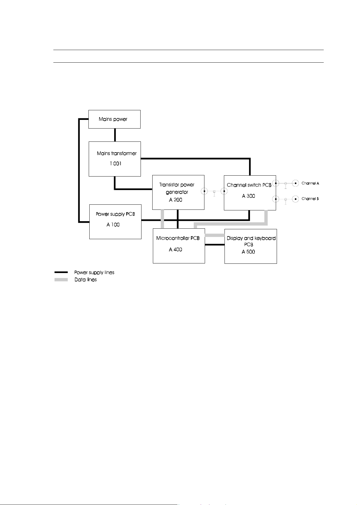
6.1 Block diagram.
6.2
6.3 Mains power and mains transformer.
The Performa+ has to be connected to the mains via the fixed power cord, with a non-fused earth
contact.
Always check whether the mains power corresponds to the mains input as indicated on the type
shield (besides the mains cable).
Note: the mains cable always has to be replaced with the same type !
The mains transformer (T001) generates 3 different output voltages :
- 45 VAC non-fused
- 26 VAC with fuse 100 mA L
- 160 VAC with fuse 100 mA L
The transformer has built-in automatic thermal fuse. It will cut-off the primary winding when the
temperature exceeds 135°C.
The transformer can be fed either with an incoming voltage of 230 VAC (+/- 15%) or with 115VAC
Page 11
Page 12

(+/- 15%).
6.4 Power supply (A100).
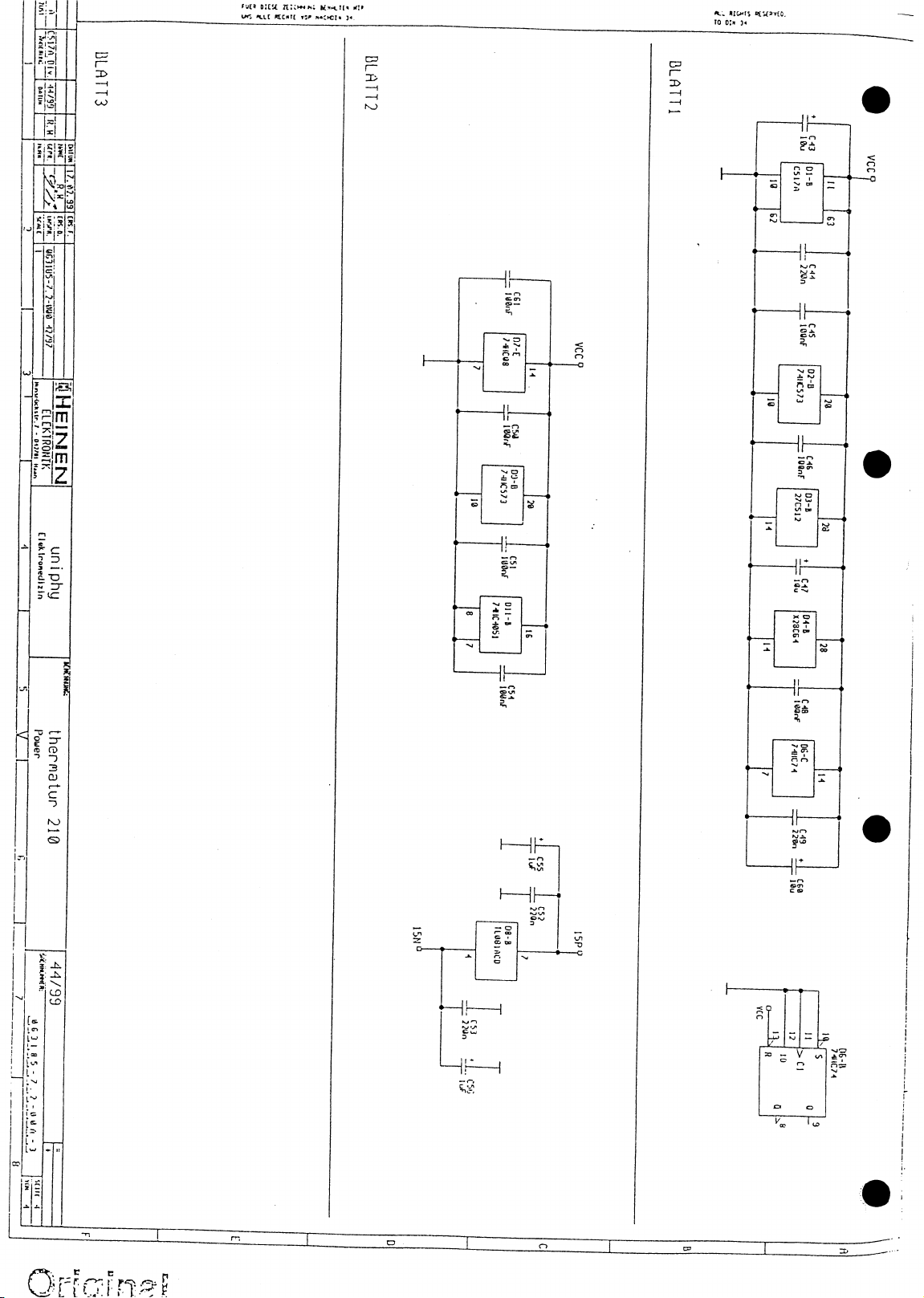
The PCB A 100 is a switched power supply, generating 3 different output voltages:
+ 15 VDC
+ 5 VDC
- 15 VDC
The power supply PCB has a 2 AL fuse.
6.5 Transistor power generator.
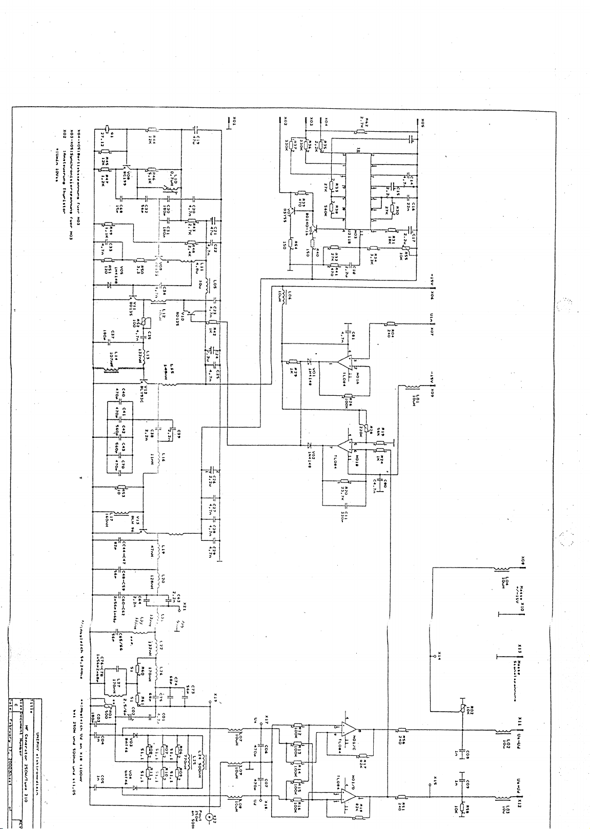
This module can be subdivided into three main sections. The first one includes the quartz stable
generator, amplification and filtration of the 27,12 MHz high-frequency power.
The second includes the measurement and control circuits that enable an exact adjustment to the
output power. The third section contains the control circuit of the operating voltage of the amplifier.
Any repair work of this sub-assembly shall only be performed by the manufacturer. However,
there are some reference voltages that can be checked to determine the exact location of a defective
part.
Please refer to chapter x for more details.
6.5.1 The quartz stable generator.
The oscillator circuit is composed round C82 (Quartz), V08, L10 and V09.
The base voltage of V08 must be about 3,6 VDC.
By means of L10, the amplitude of the signal is tuned to a voltage of about 10 Vpp to 13 Vpp.
This signal must be measured on the collector of transistor V09 (= cooling surface).
If necessary, the amplitude can be changed by adjusting the coil L10 (first take out the protective
cover).
6.5.2 The level control circuit.
The intensity level control circuit is composed around V10, L12 and V11.
The input voltage at the basis of V10 has a range from 0 to 12 V. With a voltage below +2V the level
control delivers no output power. The level control is set to full power with a voltage of about 12V to
14V.
6.5.3 The amplification circuits.
This circuit includes R252, C235,L213, V212, C238, C239, L216, V213, L219, L220, C263, C264,
L221, L222, L226, C273, C274, C275.
The main amplifier is the V13: BLW 96C that is integrated as a class C amplifier.
Page 12
Page 13

The collector voltage of V13 will remain stable at a level of about 46 VDC.
This collector voltage is automatic controlled by the operating voltage control circuit (B 4207).
The thyristor V001 is triggered by the operating voltage control circuit and charges the capacitor
C001 to 46 VDC. This is performed synchronously to the mains frequency.
6.5.4 Impedance matching and filter circuits.
The circuits around L19 and L20 match the impedance from 4 Ohm to exactly 50 Ohm.
It is important that the current consumption of the voltage control circuit (to be measured at X05)
never exceeds 10 A (at 250 Watts with a 50 Ohm load).
By matching of L19 and L20 the output resistance can be influenced, thus influencing the voltage
control current.
The circuits around L21, L22, L26, L27, R60 and R61 compose the bridged T-piece, acting like a
bandpass-filter for 27,12 MHz.
This circuit is designed in a way that the attenuation for the 27,12 MHz signal is maximum 0.3 dB.
6.5.5 Power and mismatching meter.
Includes: C201 to C205, L224, L225, R201, R211, V203, V204.
The output power is measured by means of coil L24, measuring the output voltage and output
current.
Measuring point X17 = Usum = proportional to sum of voltage and current.
Measuring point X18 = U diff = proportional to difference between voltage and current.
When the tuning between the generator and the patient is optimal (50 ohm load), there will be no
dephasing between current and voltage. As a result Udiff will be 0 and U dif will be maximum.
When the tuning is not optimal the signal Udiff will be proportional to the mismatch.
Both the signals Us and Ud are fed to the adding and subtracting amplifier, resulting in two different
signals:
X11: (Us - Ud)
X12: (Us + Ud)
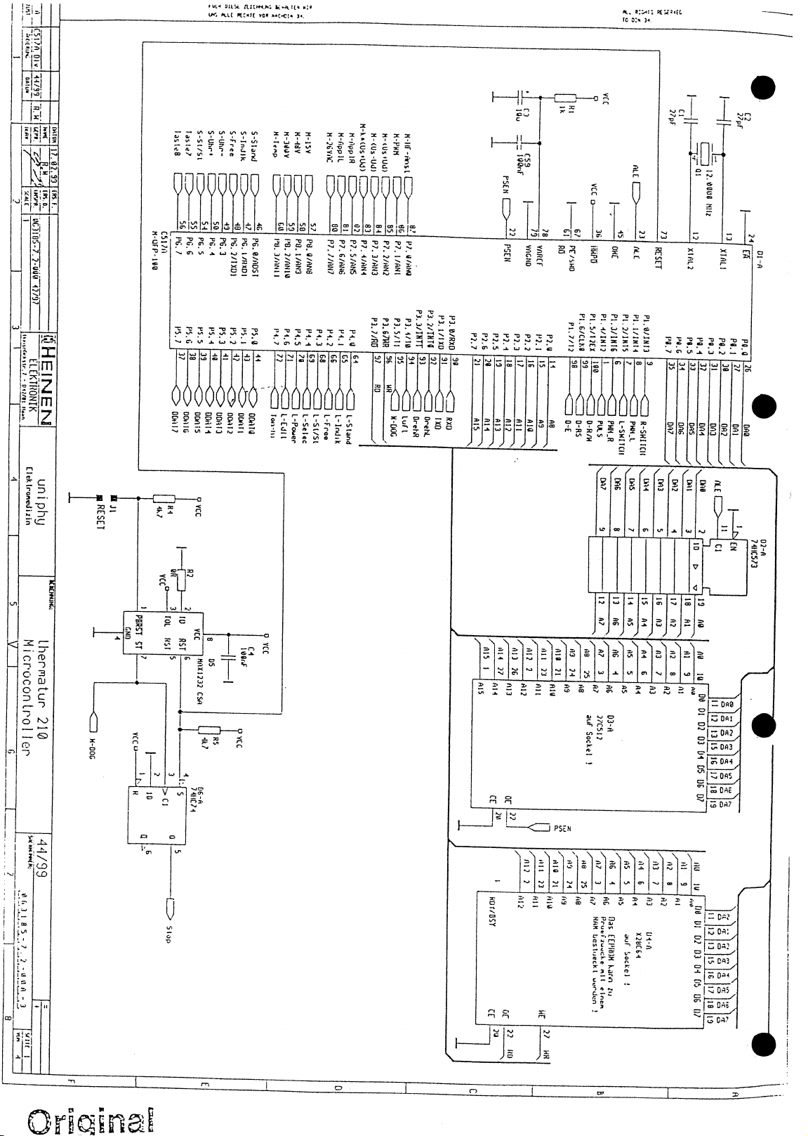
Both the signals are presented to the microprocessor, which will calculate the standing wave ratio
(SWR = S) and the power using the following formula:
Up = K (Us + Ud) x (Us – Ud).
Where K is a constant value that can be adjusted by means of R02, in order to have the same output
power as indicated on the display.
In case S = 1, there is a perfect match between the generator and the load. If S > 1.4, the unit reports
a bad contact between the applicator and the patient, and the power will be reduced to a minimum.
Page 13
Page 14

6.5.6 Setpoint and actual value comparator.
It includes: R221, R225, R226, C210, V214, N201/1.
Under normal conditions op-amp N01A will control the voltage level.
V01 will be open and V02 will be decoupled.
The cable voltage monitoring circuit is composed by opamp N01A and will be active when extreme
mismatching occurs and a high RF power is required at the same time.
In that case V01 will be decoupled and V02 will open.
The maximum power of the generator will thus always be limited to about 270 watts.
In any case only 1 opamp controls the voltage level.
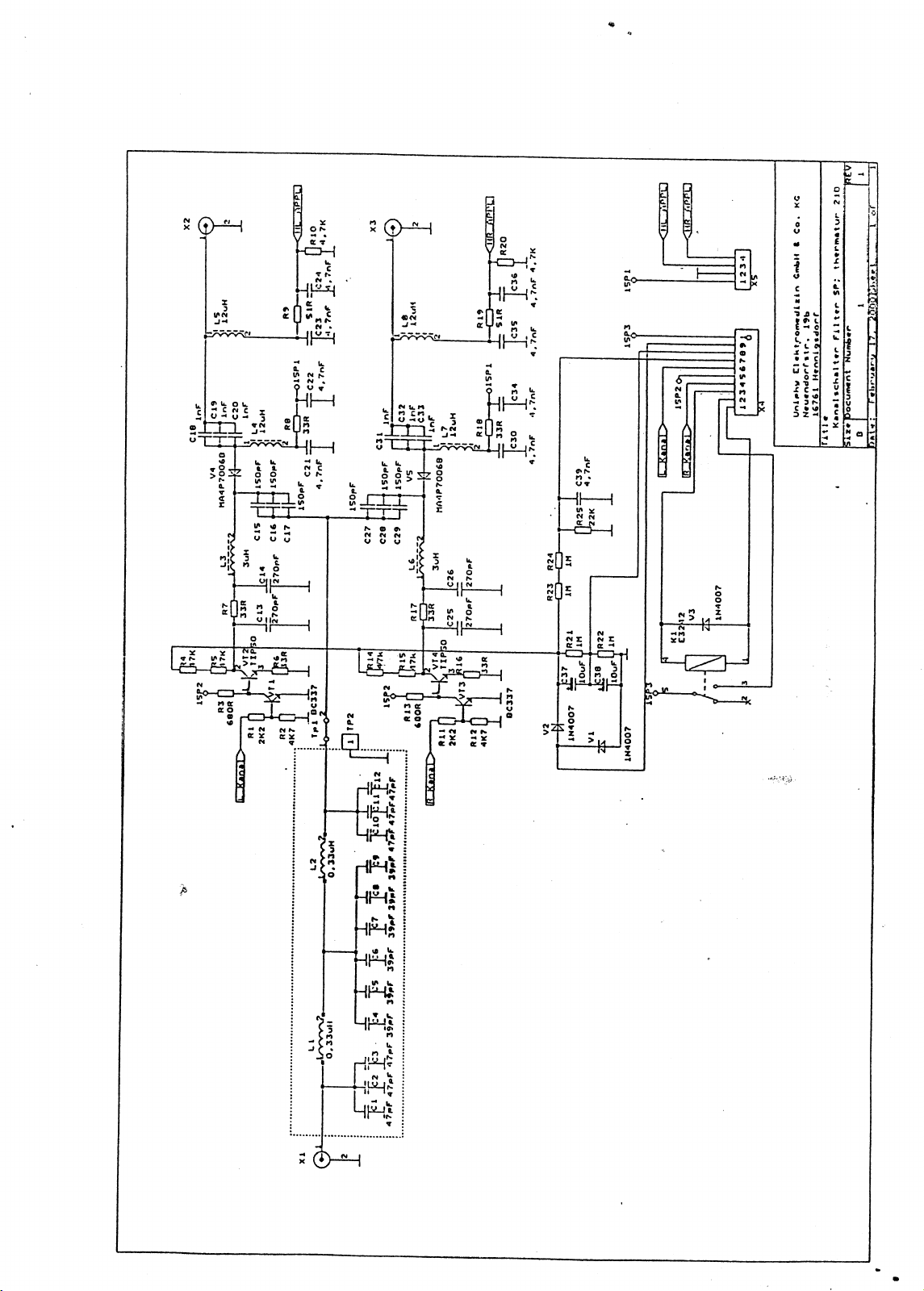
6.5.7 Channel switch PCB.
The Performa+ has two output channels ( Left channel (L) and the right channel (R)). Since there is
only 1 generator, the output power must be fed-through asynchronously to channel A and B.
The most important component for each channel are the diodes V4 and V5, acting like a High
Frequency ‘door’.
One channel will be locked by applying 400 V DC on the cathode of the diode, at the same time, the
other channel will be open.
The signals L_Kanal and R_Kanal are pulse signals which are presented synchronously with the HF
power coming in from the power generator.
There are two different coil-field electrodes.
- 14 cm coil field electrode
- 8 cm coil field electrode
The unit has a automatic electrode selection circuit. This is important to make sure that the user
cannot select the wrong applicator and damage the electrodes by giving too much power.
The signals HL_APPL and HR_APPL are the applicator detection signals for the left and the right
signals.
Page 14
Page 15
7. System diagnostics software
The unit constantly monitors a number of key-points in the unit. If any of these points exceed the
limits, the unit will give the following message:
‘ CONTACT SERVICE DEPARTMENT’
Now press the two keys that light-up (Key ‘standard mode’ and Key ‘start/stop’).
The unit will display the measuring point where an error has been detected.
To check all the measuring points, it is possible to enter the service program.
To enter the service program switch on the unit while you keep both the keys ‘Standard’ and ‘Free
mode’ pressed.
The service program displays all the different measuring points by turning the rotary knob.
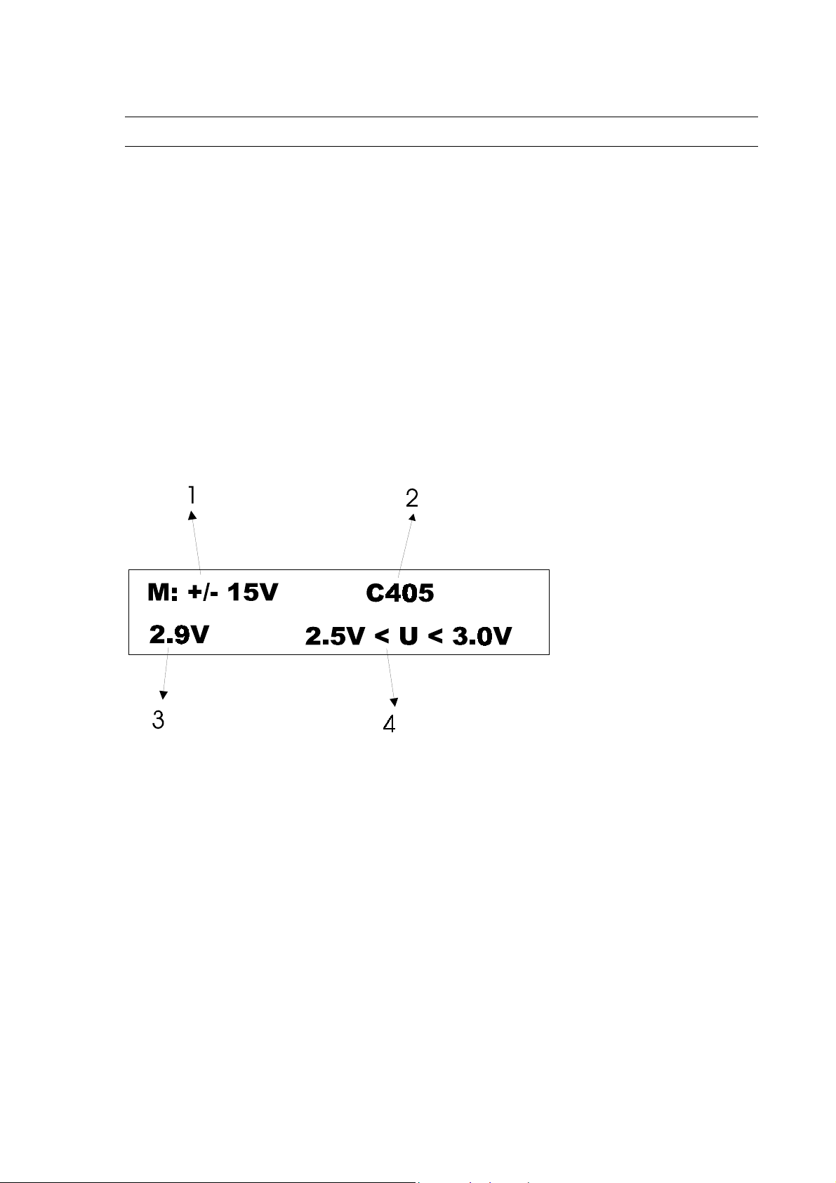
Every measuring point is indicated with an M.
Indications in the service menu:
1. Measuring point: value that is checked in this program (+15V and –15 V).
2. On which component this value is measured (capacitor C405).
3. What is the measured value (3.1V).
4. What are the limits for this value (between 2.5V and 3.0V)
It is possible that some errors are only generated when the unit is generating a HF signal.
Therefore it is possible to generate a HF output while you monitor the measured values in the service
program.
The generated HF power is a continuous signal that can be set up to 200 Watts. This power is needed
in production to check the generator parameters.
For service purpose use the table below:
Page 15
Page 16

Important remark: not following these power settings, will damage the unit.
Maximum power Maximum time
14 cm coil-field 50 watts 5 min
8 cm coil-field 50 watts 5 min
Dummy load (directly to generator) 200 watts 1 min
7.1 The service screens.
Measuring point 1:
What is measured: +/- 15 V
Where can this voltage be measured:
- Output connector of the power supply board (A100):
Black-blue: -15V
Black-red: +15 V
- On the generator:
+15 V on X06 (mass = generator housing)
-15 V on X09
- Microcontroller PCB.
On X 402 pin 1 and pin 4 (mass)
Measuring point 2:
What is measured: + 46 V DC
Where can this voltage be measured:
On C 0001 (big capacitor on top of the generator).
Measuring point 3:
What is measured: 400 V DC.
Use of this signal: this voltage is used to lock channel A or channel B.
Measuring point: X 402.5
Where can this voltage be measured: on capacitor C37 and C38, 200 VDC each.
Measuring point 4:
What is measured: temperature of the generator.
Use of this signal: to protect the generator for overheating.
Up measuring point: X 401.9
Service measuring point: temperature sensor on the right side of the generator.
Typical value: 2,7 V at 25°C
Limit values: between 1V and 4 V.
Page 16
Page 17

) The fan is able to work on two different speeds, depending on the temperature that is measured on
the cooling surface of the generator.
In order to test the high speed mode of the fan, connect a 2.7K ohm resistor between the sensor and
the cooling surface.
Measuring point 5:
What is measured: 26 VAC.
Use of this signal: synchronizing voltage for DC power source.
Up measuring point: C407
Service measuring point: X 203 on generator PCB and generator housing (mass).
Typical value (no power output): 2.8 V
Limit values: 1.8V and 3.0V
7.2 Measuring point 6
What is measured: PWM voltage
Use of the signal: DC voltage in relation to the peak power.
Up measuring point: D408.3
Service measuring point: ?
Typical value: 1.0 V
Limit values: 0V and 1.8 V
If this value is out of the limits: check the peak power adjustments.
7.3 Measuring point 7
What is measured: A200 uP input signal.
Use of the signal: signal in relation to power intensity.
UP measuring point: R409
Service measuring point: X07 on generator PCB.
Typical value (no output power): 2.0V
Limit values: between 0V and 5V.
7.4 Measuring point 8
What is measured: Us+Ud (U sum + U diff.)
Use of the signal: power calculation
UP measuring point: X 401.1
Service measuring point: X12 on generator PCB
Typical value: 2.8 V (with power 50 W cont, and S=1)
Limit value: between 0V and 4,9V
7.5 Measuring point 9
What is measured: Us-Ud (U sum - U diff.)
Use of the signal: power calculation
UP measuring point: X 401.2
Service measuring point: X11 on generator PCB
Typical value: 2.8 V (with power 100 W cont, and S=1)
Limit value: between 0V and 4,9V
Page 17
Page 18

7.6 Measuring point 10
What is measured: k x ( Us + Ud)/(Us-Ud)
Use of the signal: measured power.
UP measuring point: X 401.3
Service measuring point:
Typical value: 1.5 V (with power 100 W cont, and S=1)
0.4V (no power output)
Limit value: between 0V and 3V
7.7 Measuring point 11
What is measured: L.Electr
Use of the signal: head size detection
UP measuring point: X 402.3
Service measuring point: con X5 on channel switch PCB Black-Brown
Typical value no head connected: between 1.6V and 1.8V
Typical value 8 cm head: 0V
Typical value 14 cm head: between 0.8V and 1V.
7.8 Measuring point 12
What is measured: R.Electr
Use of the signal: head size detection
UP measuring point: X 402.2
Service measuring point: con X5 on channel switch PCB Black-Pink
Typical value no head connected: between 1.6V and 1.8V
Typical value 8 cm head: 0V
Typical value 14 cm head: between 0.8V and 1V.
Page 18
Page 19

8. Calibration of the generator.
If the unit recognises a problem, it will generally show the message ‘contact service department’.
By pressing the start/stop key and the standard mode key, the unit will show the measuring point
where an error is detected.
However, besides the 12 measuring points there are some additional error messages:
- Pulse pause too much output.
- Left/right channel too less output.
If any of the messages above appear, first check all the measuring points of the service menu, and
compare the measured values with the typical values (chapter 6).
If all the measured values appear to be correct, the generator must be recalibrated.
8.1 Generator calibration procedure.
It is strongly recommended to repeat the following calibration instruction after every repair.
8.1.1 Calibration of the start-up point of the generator.
When the unit is powered-up, the generator may not produce any HF-power. However, it must be
calibrated in a way that any additional level input of the microcontroller will result in a HF output
power.
In other words, the generator must be calibrated just before the startup point.
Calibration procedure:
1. Connect a 14 cm thermoplode to the left output connector.
2. Open the unit and the generator cover.
3. Connect a 50 Ohm dummy load directly onto the generator output socket.
4. Switch on the unit (no output power !).
5. Connect a digital multimeter to X 12 (Us +Ud) (generator PCB).
6. On the microcontroller PCB: turn potmeter (usually clockwise) until the measured voltage on X12
raises.
7. Now turn R30 counter clockwise until the voltage reaches its lowest value (typical < 0.1V).
8. Connect the multimeter to X07 (generator PCB) and read the value.
9. Adjust the measured value 100 mV less by turning R30 (typical 1.7 VDC).
8.1.2 Calibration of the maximum average power.
This procedure explains how to calibrate the maximum average power of the performa+.
It must be measured directly on the generator output.
The maximum average power is:
230 W (maximum peak power) x 0.45 (maximum duty cycle) = 103 W.
Due to attenuation of the channel switch PCB, this will result in a maximum average output power of
90 W eff.
Page 19
Page 20

Calibration procedure:
1. Connect a 14 cm thermoplode to the left output connector.
2. Open the unit and the generator cover.
3. Connect a 50 Ohm dummy load directly to the generator.
4. Switch on the unit.
5. Turn the potmeter R37 maximum clockwise (to disable the software power check).
6. In standard mode: raise the intensity to 90 W eff.
7. Measure and adjust the output power to 103 W with R202 (on generator PCB).
(Voltage on 50 Ohm dummy load: 7 VDC)
8. Now measure the voltage on R25 (left side) and adjust it with R 37 to approx. 4.4 VDC.
Page 20
Page 21
9. Unit checkup procedure
Tools required:
- Dummy Load 50/100 Ohm
- λ/2 cable
- Reference electrode
9.1 Generator power check.
Connect the dummy load (50 Ohm) directly to the generator (always use the λ/2 cable) and connect a
14 cm head on the left output channel.
Switch the unit on and select the standard mode.
Measure the voltage on the output sockets of the dummy load.
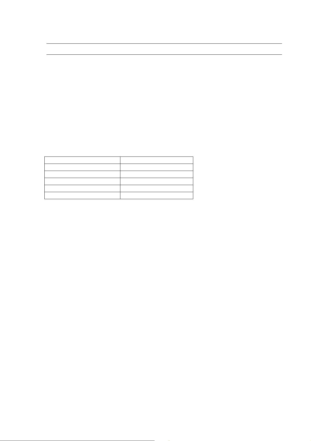
Set power (standard mode) Voltage on dummy load
4.5 Watt 1.9 VDC
27 Watt 4.0 VDC
45 Watt 5.1 VDC
72 Watt 6.3 VDC
90 Watt 6.9 VDC
9.2 Check of the SWR.
Connect the dummy load (50 Ohm) directly to the generator (always use the λ/2 cable) and connect
a 14 cm head on the left output channel.
Switch on the unit in service mode (chapter )
Press the ‘INDICATION’ key in order to select the left channel.
Turn up the intensity (50 watt , maximum 30 seconds) and check whether the SWR ratio (S) = 1
Repeat the same test with the 100 Ohm dummy load: the SWR ratio should now be 1.4 < S <1.6.
Page 21
Page 22
10. Calibration of the coil field electrode.
Tools required:
- Dummy Load 50/100 Ohm
- λ/2 cable
- Reference electrode
- Calibrated water (SWR 1)
10.1 General.
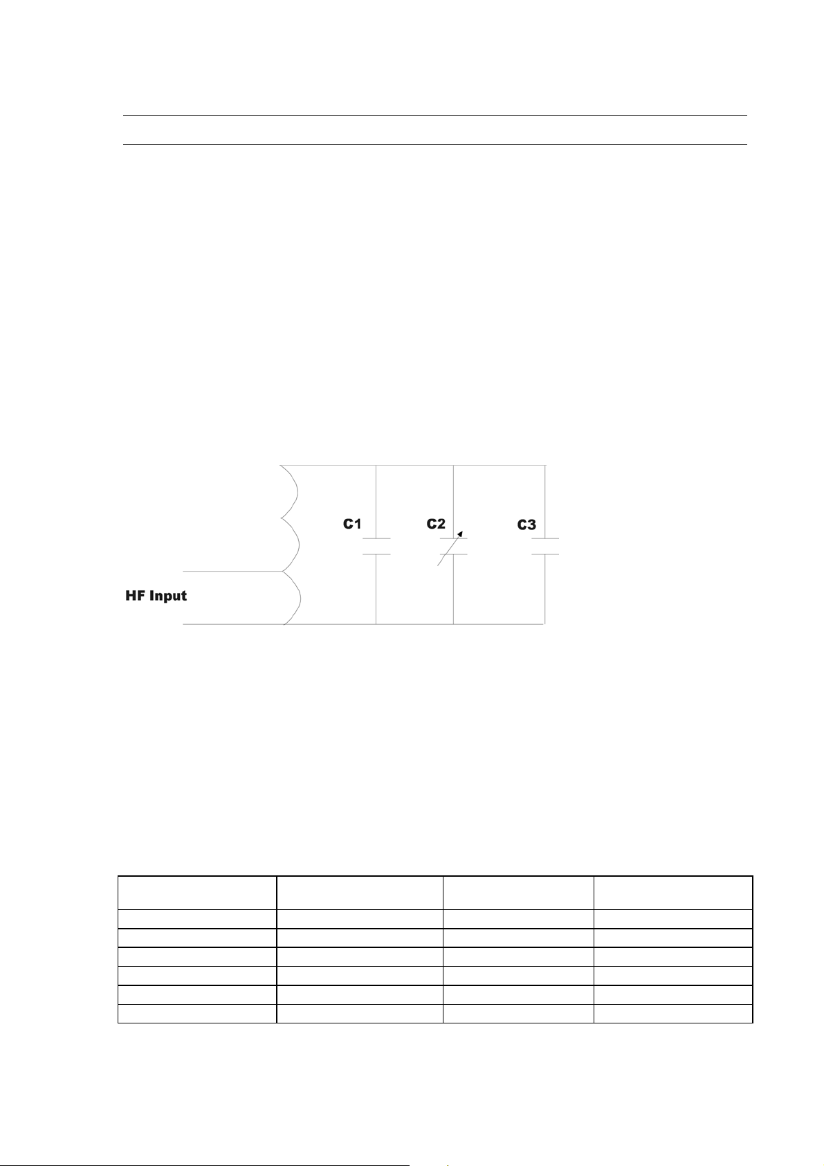
The schema of the plode consists out of three capacitors (figure below):
C1: Fixed capacitor.
C2: Tuning capacitor.
C3: Metal cage + shield
The tuning capacitor is accessible from outside, and allows a calibration of the plode.
10.2 Different types of coil field plods.
There are 2 different coil field electrodes:
14 cm coil field electrode
8 cm coil field electrode
The table below indicates the performance of each plode in all different configurations.
Left 8cm/right 8 cm 32 Watts 400 µsec 400 Hz
Left 14cm/right 14cm 64 Watts 400 µsec 800 Hz
Left 8cm/right 14 cm 32 watts 400 µsec 400 Hz
Left 14cm/right 8 cm 32 watts 400µsec 400 Hz
One plode of 8 cm 32 watts 400 µsec 400 Hz
One plode of 14 cm 90 watts 400 µsec 1125 Hz
Maximum average
power
Maximum pulse-width Maximum Frequency
Page 22
Page 23

10.3 Performance check of the electrode.
Before any adjustment on the electrodes shall be done, it is very important to make 100% sure that
the problem is the electrode and not the unit.
Therefore it is strongly recommended to first check the unit with the reference electrode and the
dummy load (chapter 8, check of the SWR).
If both the reference electrode and the dummy load appear to function perfectly on the unit, the
following calibration procedure must be done.
1. Check whether the unit recognizes the right head.
2. Connect the reference electrode to the left output connector (same size as the defective electrode).
3. Install the electrode in front of the water tank.
4. Connect the defective electrode directly to the generator by means of the λ/2 cable.
5. Switch on the unit in service mode and select the left channel.
6. Turn up the intensity to 50 watts and check whether the SWR ratio =1
7. If the SWR is different from 1, the thermoplode needs to be recalibrated.
) If the SWR is far different from 1, maybe the plode had a shock. Open the plode to check whether
the components inside are ok (chapter)
10.4 Recalibration of the plode.
1. Start up under the same conditions as indicated in 9.2.
2. Turn the intensity to zero.
3. Adjust the capacitor with one turn and remove the screwdriver (photo)
4. Turn up the intensity and check whether the SWR changed in the right direction.
5. Readjust the capacitor electrode if necessary.
) Always remove the screwdriver before checking the SWR.
) If the value SWR = 1 cannot be reached, the plode must be sent to Uniphy for recalibration with
specialized measuring equipment.
10.5 Contact control.
The unit permanently controls the contact between plode and patient. This system is integrated for
different reasons:
- In case of A-thermic treatment, the patient will not feel any heat. Without a contact control,
the patient wouldn’t know if he is close enough to the plode, in order to assure an effective
treatment.
- When the patient moves away from the plode, a part of the forwarded HF energy will be
reflected.
As a result, the plode will start heating-up, more than usually, and there will be a risk of
burning the plode and the patient (when he touches the plode).
The maximim temperature of the plode is limited to 55°C.
If the unit measures a SWR > 1.4, the display will indicate the message: ‘improve position of coil
field electrode’.
Page 23
Page 24

In order to have a SWR of 1 during treatment, the following conditions must be fulfilled:
- The treated tissue is at least as large as the surface of the electrode.
- The coil field electrode must touch the patient.
- The treated tissue contains enough water.
If any of these conditions are unfulfilled, the SWR ratio be higher.
10.6 Opening the coil field electrode.
1. Remove the front cover (3 screws).
2. Check if there are any irregularities inside the plode.
3. When really necessary open the rest of the plode (step 4-6)
4. Remove the shield on top.
5. Remove the metal cage.
6. Replace parts is necessary.
7. Reassemble the plode.
8. Repeat the calibration procedure (9.3).
) The shield and the metal cage are parts that may influence the calibration. Only open the cage when
it is really necessary.
Page 24
Page 25

11. Photo’s of the different parts.
11.1.1
Page 25
Page 26

12. Spare parts
Page 26
Page 27

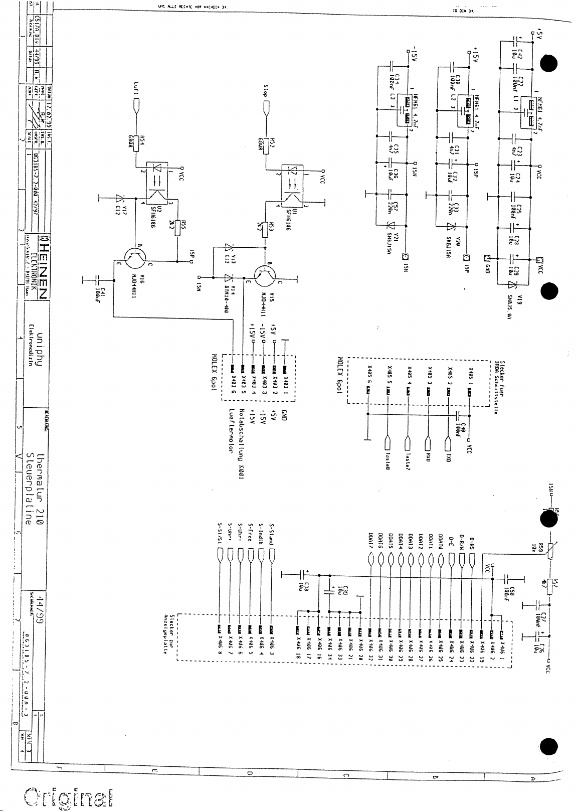
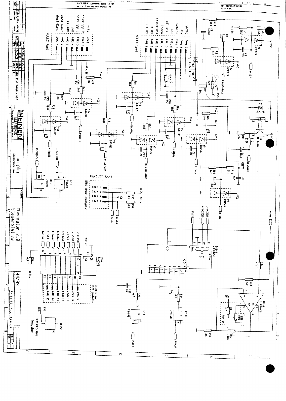
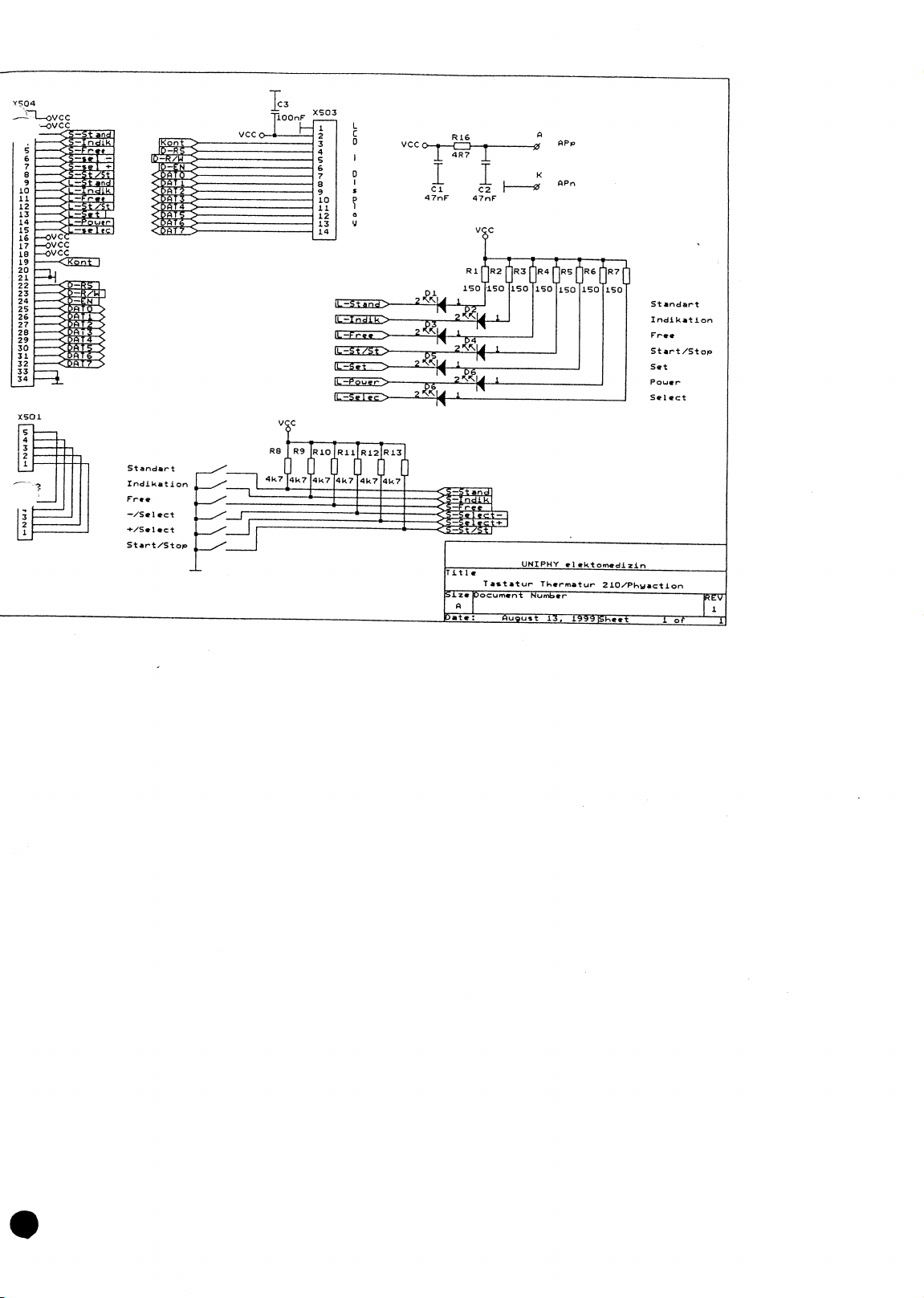
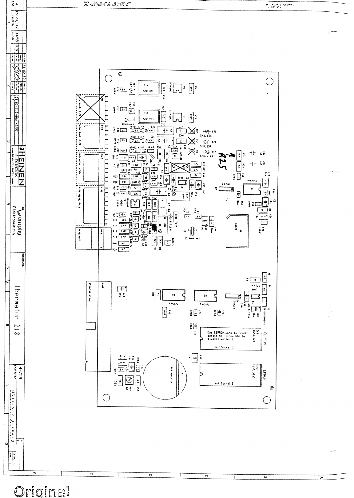
13. Circuit diagrams
Page 27
Page 28
Page 29
Page 30
Page 31
Page 32
Page 33
Page 34
Page 35
 Loading...