

Page 1
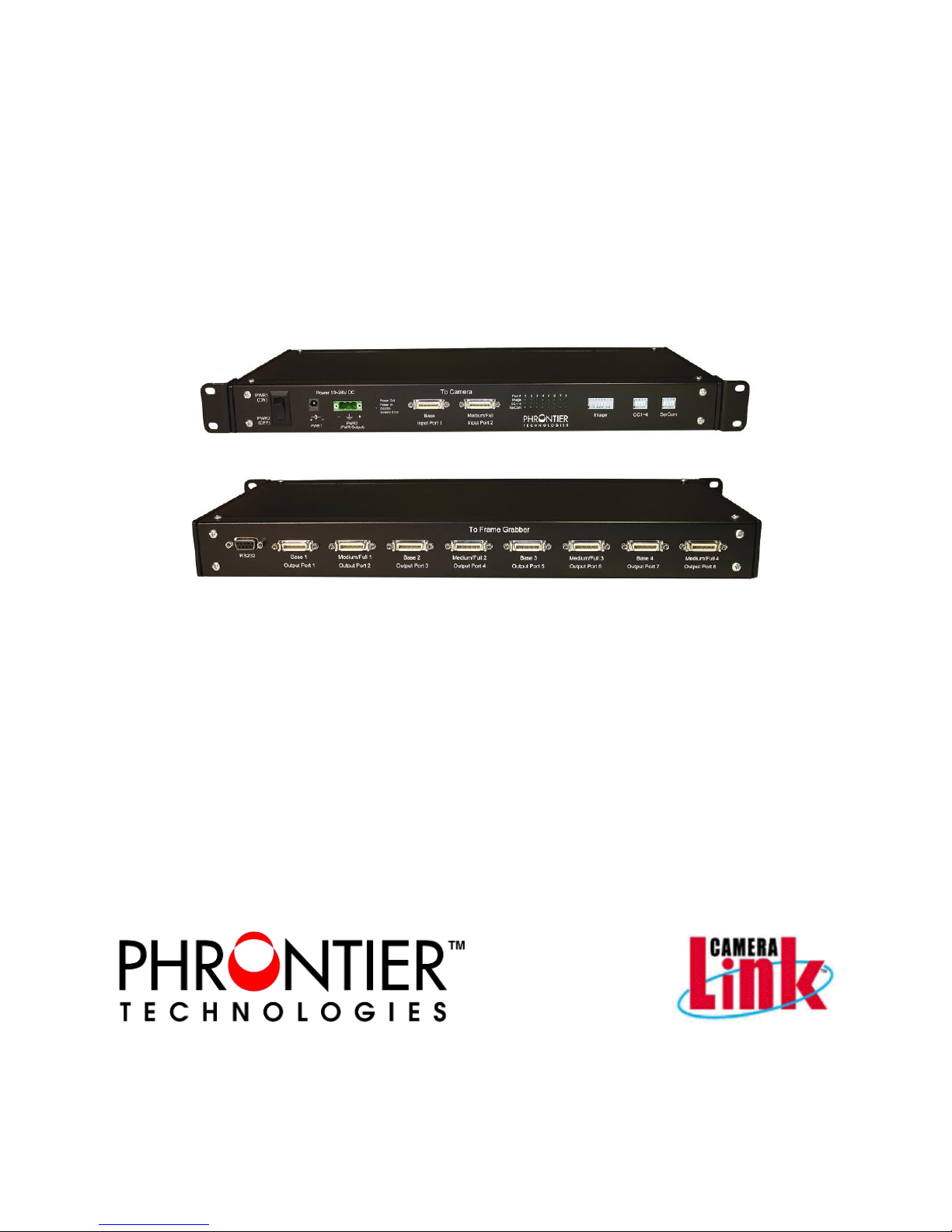
Camera Link Splitter/Repeater
Base/Dual Base/Medium/Full/Extended Full
TM
PHANTA
User Manual V1.4
PHANTA-V1.4
PHANTA-S1F4
PHANTA-D2B4
PHANTA-S1B8
Page 2

2
TABLE OF CONTENTS
1. Introduction ............................................................................................................................. 3
2. Available models ..................................................................................................................... 3
3. Packing List ............................................................................................................................. 3
4. Model Functionality ................................................................................................................ 4
4.1 PHANTA-S1F4 ............................................................................................................ 4
4.2 PHANTA-D2B4 ............................................................. Error! Bookmark not defined.
4.3 PHANTA-S1B8 ............................................................. Error! Bookmark not defined.
5. DC Input Power Connection and Options ............................................................................... 6
5.1 PWR1 port ................................................................................................................... 7
5.2 PWR2 port ................................................................................................................... 7
5.2.1 PWR2 for DC input ............................................................................................... 7
5.2.2 PWR2 for DC output (consult technical support before using this configuration) ... 7
6. Setting Signal Routing ............................................................................................................. 8
6.1 DIP Switches ............................................................................................................... 8
6.1.1 Image DIP switch .................................................................................................. 8
6.1.2 CC1~CC4 and SerCom DIP switches ................................................................... 8
6.2 RS232 port .................................................................................................................. 9
6.2.1 Pin assignment ..................................................................................................... 9
6.2.2 Shift registe r settings ............................................................................................ 9
6.2.3 Programming Commands ....................................................................................11
6.2.4 Hyper Terminal Setup ..........................................................................................11
6.2.5 Programming Examples Using Hyper Terminal ....................................................13
7. LED Indicators ...................................................................................................................... 14
8. Specifications......................................................................................................................... 15
8.1 General Specification ..................................................................................................15
8.2 Camera Link Interface .................................................................................................15
8.3 Mechanical Dimensions (mm) .....................................................................................15
9. Contact Us ............................................................................................................................. 16
TABLES
Table 1. CC1~CC4 and SerCom DIP switch settings ................................................................. 9
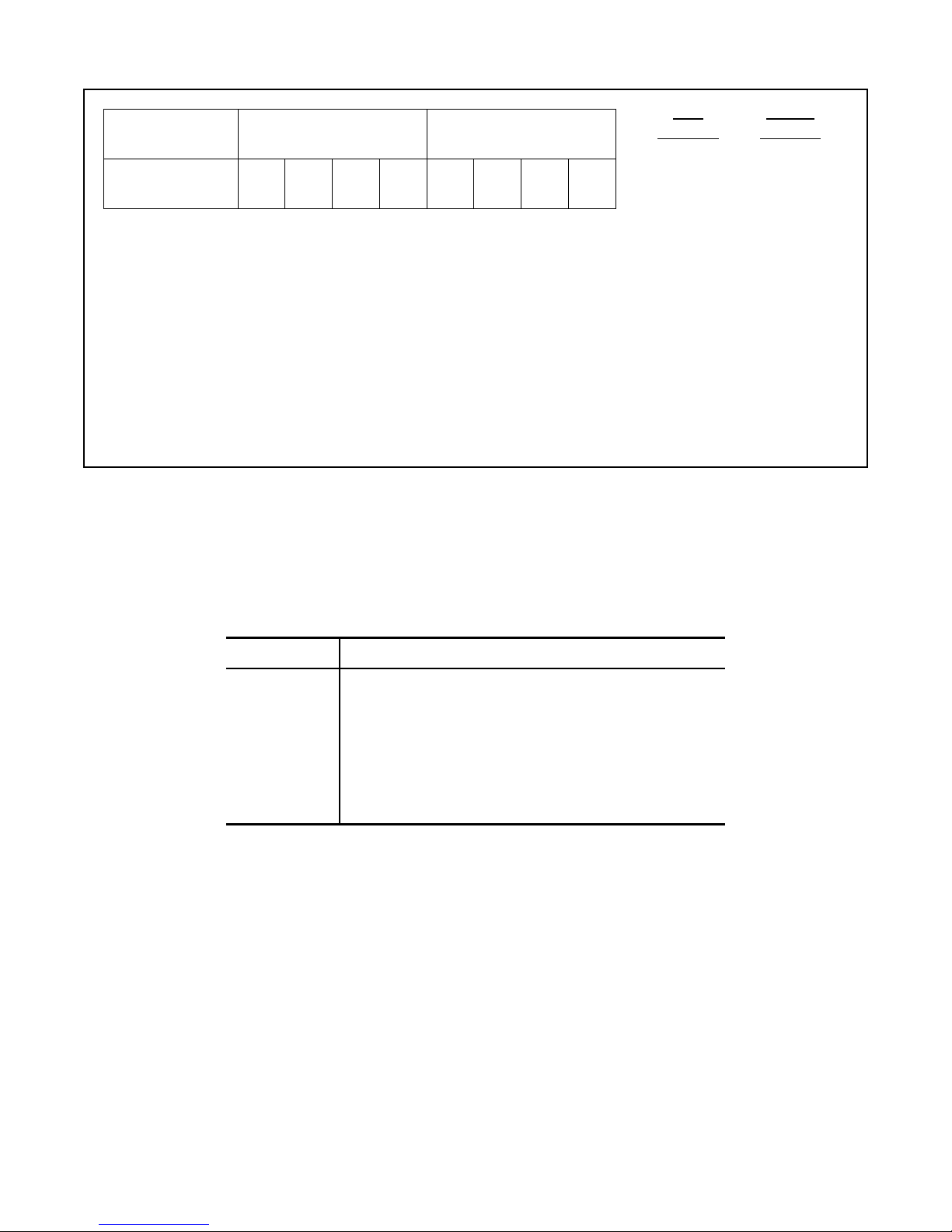
Table 2. Relationship between the hex command numbers and shift register settings ..............11
Table 3. Commands for setting the shift registers .....................................................................11
Table 4. Definition of the 1x3 LED indicator ..............................................................................14
FIGURES
Figure 1. Block Diagram of PHANTA-S1F4 ................................................................................ 4
Figure 2. Block Diagram of PHANTA-D2B4 ............................................................................... 5
Figure 3. Block Diagram of PHANTA-S1B8 ................................................................................ 6
Figure 4. Simplified DC input circuit diagram (not for PWR2 as an output). ................................ 6
Figure 5. Jumper settings for PWR2 .......................................................................................... 8
Figure 6. RS232 Port Pin Assignment (DB9 Female) ................................................................. 9
Figure 7. Settings of the COM port property for the Hyper Terminal ..........................................12
Figure 8. ASCII Settings for Hyper Terminal. ............................................................................13
Figure 9. Starting message when RS232 communication is successfully established. ..............13
PHANTA User Manual V1.4
Page 3

3
1. Introduction
The PHANTA product family is designed to distribute image data from a high speed Camera
Link camera to multiple frame grabbers for applications that require intensive or parallel image
processing. Three models are available for different system setup. Key features include:
Fully supports Camera Link cameras and frame grabbers up to 85MHz pixel clock for
full/medium/base and 10 taps x 8 bits configurations
Independently controlled image data path, control signal path and serial communication path
for maximum signal routing flexibility
Allow users to select any of the connected frame grabbers to control and configure cameras
Signal routing can be controlled via DIP switch or RS232 port
Output ports can be shut off independently when not in use to avoid signal glitch to frame
grabbers
Reconditioned and synchronized output effectively double the connection distance
Standard 1U 19” chassis for easy mounting
An array of LED indicators clearly display operation status
Accept wide range 10V~24V DC power supply
Locking power supply connector for secure connection in industrial environment
Alternative input power terminal for easy custom power supply connection
Provides optional DC output power for cameras to save additional power supply
Can be seamlessly used with our PHOX, PHIRE and PHAST fiber extenders for extended
distance
2. Available models
PHNATA-S1F4
PHNATA-D2B4
PHNATA-S1B8
The available models are different in hardware circuitry and FPGA program which cannot be
changed in the field. Users need to specify the model for their applications at the time of
purchase.
Connects 1 full/medium/base camera to 4 frame grabbers
Connects 2 base cameras to 2 groups of 4 frame grabbers
Connects 1 base camera to 8 frame grabbers
3. Packing List
Standard package include the following items:
Items/Description Qty
PHANTA in 19” chassis with mounting bracket 1
International AC/DC adapter (12V DC out) with
Switchcraft 760BK locking plug
DB9 6 ft. male to female straight RS232 cable 1
1
User Manual 1
PHANTA User Manual V1.4
Page 4
4
4. Model Functionality
CM Base
Image Port
A, B, C
Image Port
D,E,F,G,H
CC1~CC4
CM Medium/Full
SerTFG
SerTC
Selector
SW2
SW4
SW6
SW8
SW1
SW3
SW5
SW7
Selector
FG Port 2
FG Port 3
FG Port 5
FG Port 6
FG Port 7
FG Port 8
FG Port 4
FG Port 1
4.1 PHANTA-S1F4
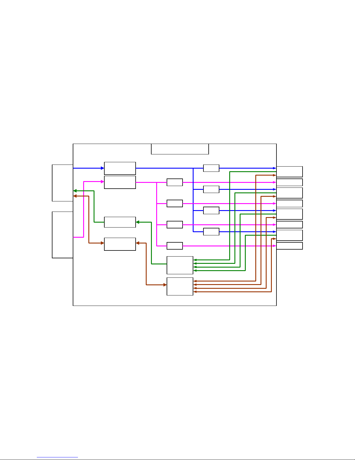
This model distributes image data from one camera to four frame grabbers. It supports base,
medium, full and extended full (10 taps x 8 bits) camera configurations. User can select any of
the frame grabbers to send camera control signals (CC1 ~ CC4) to the camera or to establish
serial communication with the camera. Since the signal paths are independently controlled, the
control signals and serial communication signals can be sent from different frame grabbers.
Selection can be done manually by DIP switches on the front panel or electronically through the
RS232 port on the back panel. The image data to each output port can be individually switched
on/off manually by the DIP switch or electronically through the RS232 port. The block diagram
of this model is shown in Figure 1.
(Input Port 1)
(Input Port 2)
4.2 PHANTA-D2B4
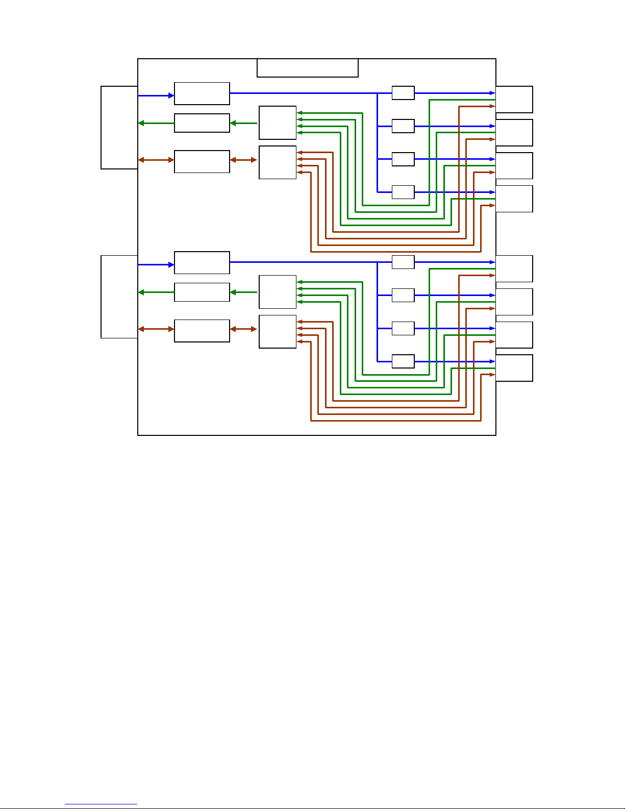
This model distributes image data from two independent base configuration cameras to four
frame grabbers for each camera. The model can be considered as two 1-to-4 image splitters
integrated in the same chassis. Camera input 1 sends images to output ports 1, 2, 3, and 4.
Camera input 2 sends images to outputs 5, 6, 7 and 8. User can select any of the four frame
grabbers in the group to send camera control signals (CC1 ~ CC4) to the camera or to establish
serial communication with the camera. Because the signal paths are independently controlled,
the control signals and serial communication signals can be sent from different frame grabbers
in the group. Selection can be done manually by the DIP switches on the front panel or
electronically through the RS232 port on the back panel. The image data to each output port
can be individually switched off manually by DIP switch or electronically through RS232 port.
The block diagram of this model is shown in Figure 2.
PHANTA User Manual V1.4
Figure 1. Block Diagram of PHANTA-S1F4
Page 5
5
PHANTA-D2B4
CM Base
Image Port
A, B, C
CC1~CC4
SerTFG
SerTC
Selector
SW1
SW2
SW3
SW4
Selector
FG Port
FG Port
FG Port
FG Port
CM Base
Image Port
A, B, C
CC1~CC4
SerTFG
SerTC
Selector
SW5
SW6
SW7
SW8
Selector
FG Port
FG Port
FG Port
FG Port
1
(Input Port 1)
2
3
4
5
(Input Port 2)
6
7
8
4.3 PHANTA-S1B8
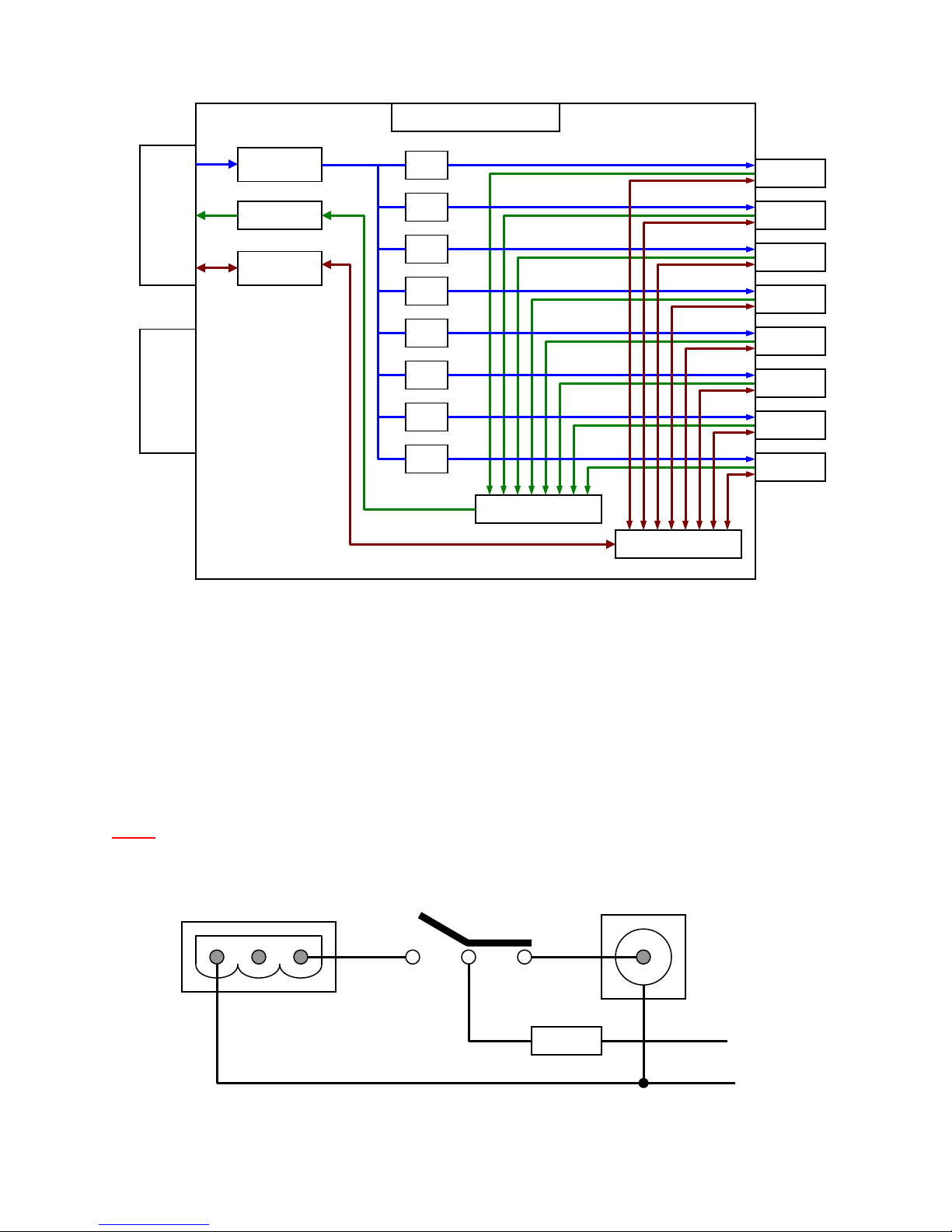
This model distributes image data from one single base configuration camera to eight frame
grabbers. Input port 2 is disabled and not used. Users can select any of the frame grabbers to
send camera control signals (CC1 ~ CC4) to the camera or to establish serial communication
with the camera. Because the signal paths are independently controlled, the control signals and
serial communication signals can be sent from different frame grabbers. Selection can be done
manually by the DIP switches on the front panel or electronically through the RS232 port on the
back panel. The image data to each output port can be individually switched off manually by the
DIP switch or electronically through the RS232 port. The block diagram of this model is shown
in Figure 3.
PHANTA User Manual V1.4
Figure 2. Block Diagram of PHANTA-D2B4
Page 6
6
CM Base
Image Port
A, B, C
CC1~CC4
Input Port 2
PHANTA-S1B8
SerTFG
SerTC
Selector
SW1
SW2
SW3
SW4
SW5
SW6
SW7
SW8
Selector
FG port 1
FG port 2
FG port 3
FG port 4
FG port 5
FG port 6
FG port 7
FG port 8
VIN -
Fuse
PWR1
PWR2
Rocker Switch
(Input Port 1)
(not in use)
Figure 3. Block Diagram of PHANTA-S1B8
5. DC Input Power Connection and Options
PHANTA product family requires an external DC power input within the range of 10V~24V. Two
power ports, PWR1 and PWR2, on the front panel provide users with options for power
connection. A rocker switch provides the switching function between these two ports as well as
the power ON/OFF function for the system. A simplified input circuit is shown in Figure 4.
Note: When re-booting the system, please allow at least 5 seconds interval before switch
on again. This will allow the internal capacitors to be fully discharged.
Figure 4. Simplified DC input circ u it diagram (not for PWR2 as an output).
PHANTA User Manual V1.4
Page 7
7
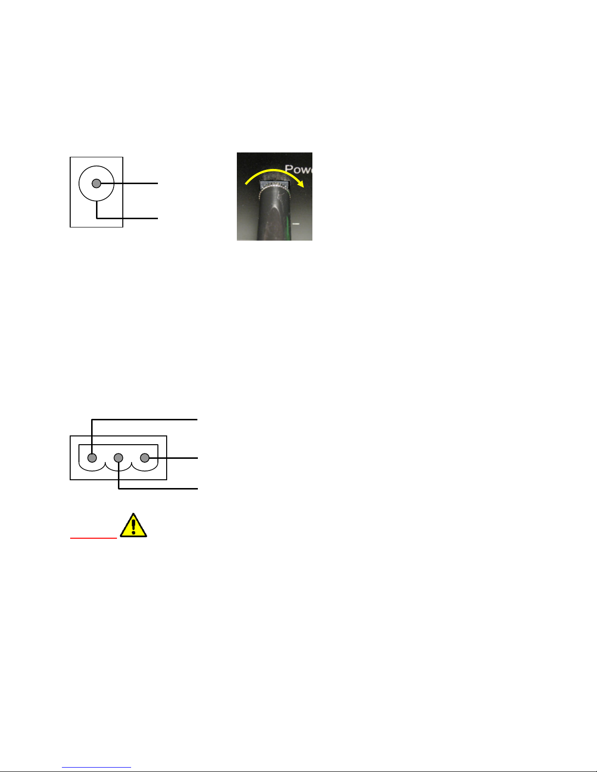
5.1 PWR1 port
-
VIN -
VIN +
Case GND
PWR1 port features a 2.5mm locking socket and is used by default as the primary DC input
port. A matching locking plug is provided in the package with the AC/DC adapter. Plugging in
the power plug and turning it clockwise will lock the plug to prevent the power cable from
disconnection. When detaching the power cable, hold the metal ring of the power plug and turn
counter-clockwise to release the locking mechanism. Pin assignment is shown below.
VIN
5.2 PWR2 port
PWR2 is a 3-pin terminal block which serves as an alternative DC input connection when direct
wire connection is desired. This port can also be configured to bypass the DC input from PWR1
and serves as a DC output port for supplying camera power.
5.2.1 PWR2 for DC input
By default this port is used as an alternative DC input and allows wire connection to user’s own
power supply. Only one, either PWR1 or PWR2, should be connected to the power supply at
one time but not both at the same time. Pin assignment is shown below.
Warning: When external power supply has separate case ground and return power
line, VIN- must be connected to the return power and NOT the external case ground.
Failure to do so will result in improper grounding and could cause permanent damage to
the system.
5.2.2 PWR2 for DC output (consult technical support before using this
configuration)
PWR2 can be configured to connect to the DC input from PWR1 to serve as a DC output port.
This circuit connection bypasses all internal PHANTA circuitry including the rocker switch and
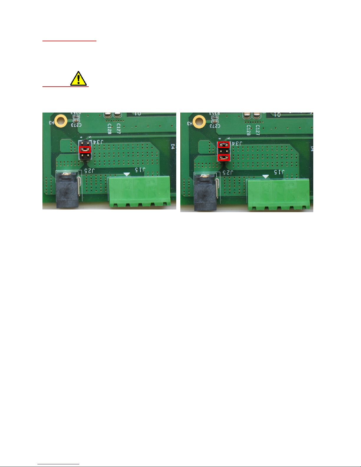
requires opening box and resetting the jumper (J34) behind the power socket to the correct
positions. Figure 5 shows the corresponding jumper position for different functions. When
PWR2 is set to output power, the LED indicator “power out” will light up and PWR2 will stay
connected to PWR1 regardless the position of the rocker switch.
PHANTA User Manual V1.4
Page 8
8
Important notes: The bypassed DC output does not have fuse protection. Circuit
By default, PWR2 as DC input
PWR2 as DC output
protection should be provided by the external device itself. Total power consumption
(PHANTA + external device) should not exceed the limits of the primary power supply
connected to PWR1.
Warning
load not a power source. Failure to do so can damage either power source connected to
PWR1 or PWR2.
: When PWR2 is set to output power, it must be connected to an electrical
Figure 5. Jumper settings for PWR2
6. Setting Signal Routing
Signal routing can be set manually via three DIP switches on the front panel or through the
RS232 port on the back panel. Details are provided in the following sections. Every time when
the unit is powered on, the unit will be reset to the manual control.
6.1 DIP Switches
Three DIP switches denoted on the front panel as image (8 positions), CC1~CC4 (4 positions)
and SerCom (4 positions) are used to set the signal routing for image data, camera control and
serial communication respectively.
6.1.1 Image DIP switch
The 8 positions of image DIP switch serves as an ON/OFF switch for individual image output
ports. The numbers on the DIP switch correspond to the numbers of the output ports. When the
image data is active on the output port, the corresponding LED will light up.
6.1.2 CC1~CC4 and SerCom DIP switches
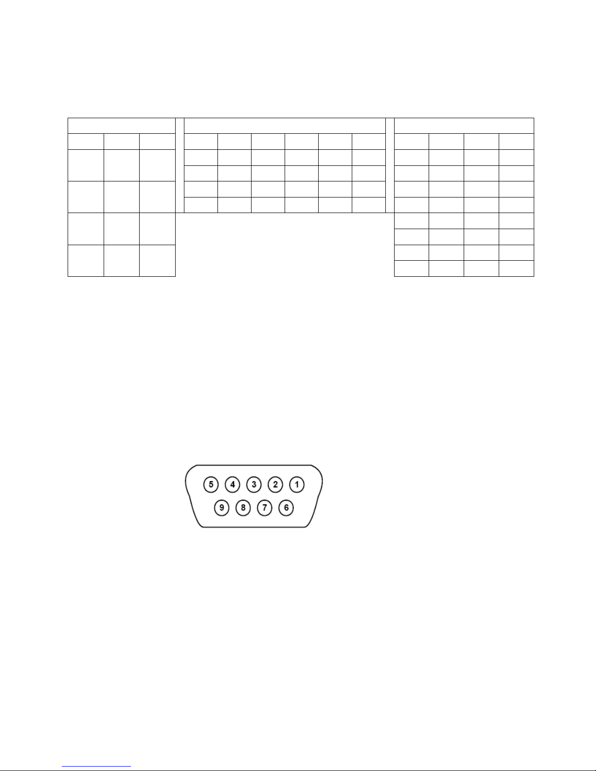
The two 4-position DIP switches, CC1~CC4 and SerCom, are used to select corresponding
frame grabbers for camera control and serial communication. In principle, each position
represents a binary number representation of the available frame grabbers. A complete table of
DIP switch settings is shown in Table 1 for each model. Users need to select the correct
PHANTA User Manual V1.4
Page 9
9
corresponding frame grabbers to send control signals to camera or establish serial
PHANTA-S1F4
PHANTA-D2B4
PHANTA-S1B8
Pos 3
Pos 4
Active
Pos1
Pos 2
Active
Pos 3
Pos 4
Active
Pos 2
Pos 3
Pos 4
Active
OFF
OFF
Port 5
OFF
OFF
Port 1
OFF
OFF
OFF
Port 1
OFF
ON
Port 6
OFF
ON
Port 2
OFF
OFF
ON
Port 2
ON
OFF
Port 7
ON
OFF
Port 3
OFF
ON
OFF
Port 3
ON
ON
Port 8
ON
ON
Port 4
OFF
ON
ON
Port 4
ON
OFF
OFF
Port 5
ON
OFF
ON
Port 6
ON
ON
OFF
Port 7
ON
ON
ON
Port 8
1, 4, 6, 7, 8, 9: NC
communication link between camera and frame grabbers. The selected frame grabber ports will
be shown on the LED indicators on the front panel.
OFF OFF
OFF ON
ON OFF
ON ON
Port 1
(CH1)
Port 3
(CH2)
Port 5
(CH3)
Port 7
(CH4)
Table 1. CC1~CC4 and SerCom DIP switch settings
6.2 RS232 port
6.2.1 Pin assignment
The RS232 port on the back panel allows users to set signal routing through a computer COM
port. A male-to-female DB9 straight cable is included in our standard package. The pin
assignment of the female DB9 connector on the back panel is shown in Figure 6.
2: TxD
3: RxD
5: GND
Figure 6. RS232 Port Pin Assignment (DB9 Female)
6.2.2 Shift register settings
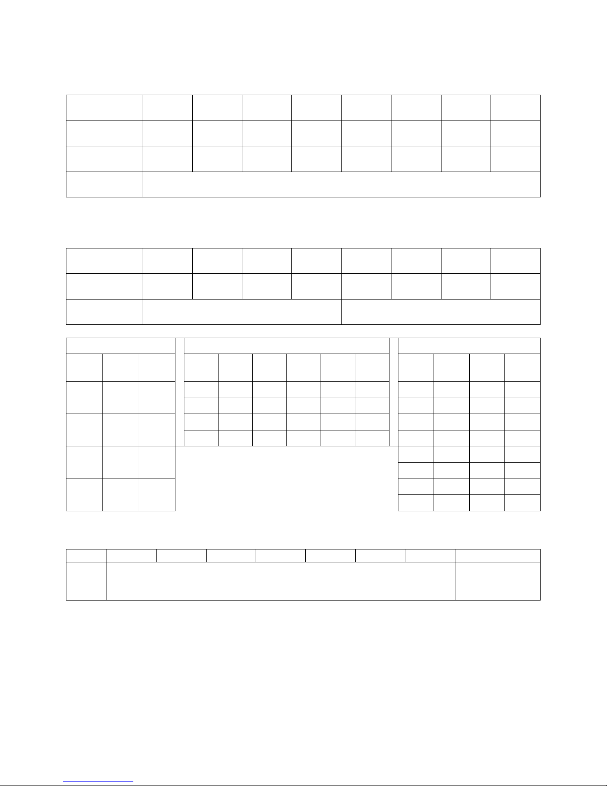
Three shift registers (SR) named, <IMG>, <SCC> and <CFG>, are used for system
configuration. Each shift register contains an 8-bit binary data. The binary settings can be
corresponded to the DIP switch settings described in the previous section. The status of each
DIP switch position represents a binary status in the shift register. Tables below show the
contents of the shift registers and the correspondence to the DIP switch positions.
PHANTA User Manual V1.4
Page 10
10
<IMG>: Turn the image output on and off. The status of each bit refers to the settings of each
Output port
number
DIP SW
position
Shift registe r
address
Content
description
DIP SW
position
Shift registe r
address
Content
description
PHANTA-S1F4
PHANTA-D2B4
PHANTA-S1B8
Bit 5
Bit 1
Bit 4
Bit 0
Bit 7
Bit 3
Bit 6
Bit 2
Bit 5
Bit 1
Bit 4
Bit 0
Bit 6
Bit 2
Bit 5
Bit 1
Bit 4
Bit 0
0 0
Port 5 0 0
Port 1 0 0 0
Port 1 0 1 Port 6 0 1
Port 2 0 0 1
Port 2
1 0
Port 7 1 0
Port 3 0 1 0
Port 3
1 1
Port 8 1 1
Port 4 0 1 1
Port 4
1 0 0
Port 5 1 0 1 Port 6
1 1 0
Port 7
1 1 1
Port 8
Name
Bit 0
Bit 1
Bit 2
Bit 3
Bit 4
Bit 5
Bit 6
Bit 7
Control options
0 = DIP switch
output port.
8 7 6 5 4 3 2 1
8 7 6 5 4 3 2 1
Bit 7 Bit 6 Bit 5 Bit 4 Bit 3 Bit 2 Bit 1 Bit 0
Set image output 1=ON, 0= OFF
<SCC>: Set the active ports for serial communication and camera control. All unused bits were
set to 0 by default.
1 2 3 4 1 2 3 4
Bit 7 Bit 6 Bit 5 Bit 4 Bit 3 Bit 2 Bit 1 Bit 0
Set SerCom active port number Set CC1~CC4 active port number
0 0
0 1
1 0
1 1
Active
Port 1
(CH1)
Port 3
(CH2)
Port 5
(CH3)
Port 7
(CH4)
Active
Active
Active
<CFG>: Set the control method either through RS232 or DIP switch.
CFG Reserved and were set to 0 by default
1 = RS232
While the actual settings are stored as a binary form in the shift register, these binary numbers
need to be converted to hexadecimal numbers when users send the commands. Two
hexadecimal numbers are needed to represent the 8-bit shift register. The value of the first hex
number is equal to the 4 MSB (bit 4 to bit 7). The value of the second hex number is equal to
the 4 LSB (bit 0 to bit 3). For users’ convenience, the relationship between the two hex numbers
and the 8-bit binary settings are shown in Table 2 as well as the conversion between the hex
and binary numbers. Programming examples will be shown in section 6.2.5.
PHANTA User Manual V1.4
Page 11
11
Hex
Binary
0
0 0 0
0
1
0 0 0
1
2
0 0 1
0
3
0 0 1 1 4
0 1 0
0
5
0 1 0
1
6
0 1 1
0
7
0 1 1
1
8
1 0 0 0 9
1 0 0
1
A
1 0 1
0
B
1 0 1
1
C
1 1 0
0
D
1 1 0
1
E
1 1 1
0
F
1 1 1
1
Hex command
numbers
st
1
number 2nd number
Number
Number
Shift registe r
settings
Bit 7 Bit 6 Bit 5 Bit 4 Bit 3 Bit 2 Bit 1 Bit
0
Example 1:
<IMG> = 0111 0101
Hex number = 75
Results for all models = turn on image transmission on output ports
1, 3, 5, 6 and 7.
Example 2:
<SCC> = 00010010
Hex number = 12
Results for PHANTA-S1F4= establish sercom on frame grabber 2
(port 3) and camera control on frame grabber 3 (port 5)
Table 2. Relationship between the hex command numbers and shift register settings
6.2.3 Programming Commands
Table 3 lists the commands for setting the shift registers. The commands are followed by a
space and two hex numbers converted from the desired binary settings. When the unit receives
a valid command, it will return “1” to confirm.
Commands Description
“L” or “l”
“I” or “i”
“S” or “s”
“C” or “c”
“W” or “w”
List all current settings
Set register <IMG> settings
Set register <SCC> settings
Set register <CFG> settings
Write current setting to the non-volatile memory
Table 3. Commands for setting the shift registers
6.2.4 Hyper Terminal Setup
Users can use the Hyper Terminal in the Windows operating system to send the RS232
commands to the module. The setup is described below.
Step 1: Power off the PHANTA box.
Step 2: Connect the RS232 port to computer COM port with the provided RS232 cable.
Step 3: Open the Hyper Terminal window by click on Start >> All programs >> Accessories
>> Communications >> Hyper Terminal.
Step 4: Enter a name in the “Connection Description” window.
Step 5: In the following “Connect To” window, set the row “connect using” to the COM port
(COM1 or COM2) where the RS232 cable is connected.
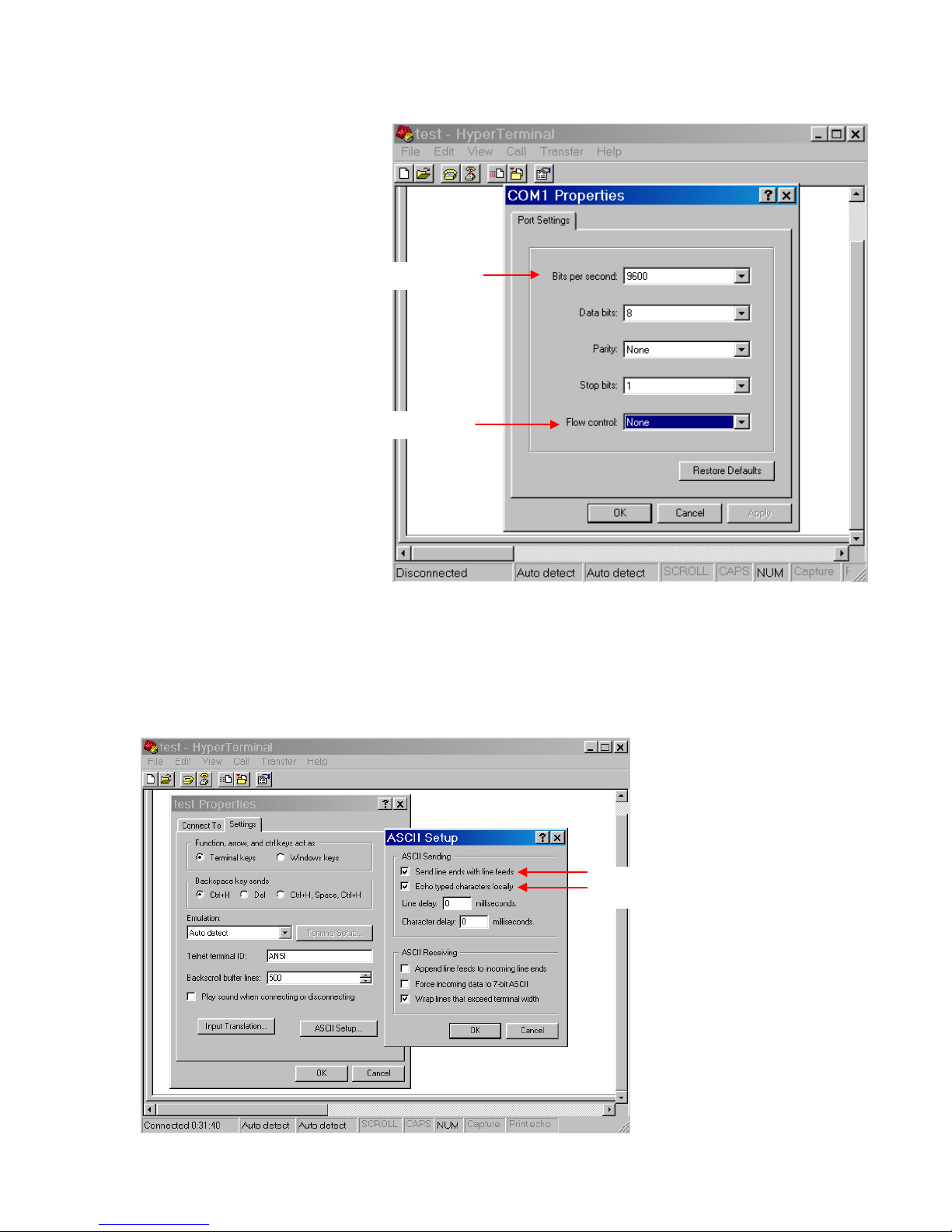
Step 6: In the following “COM1 Property”, set the following parameters as shown in Figure
7.
PHANTA User Manual V1.4
Page 12
12
Select these two options
Set to 9600
No flow control
Bits per second = 9600
Flow control = None
Data bits = 8
Parity = None
Stop bits = 1
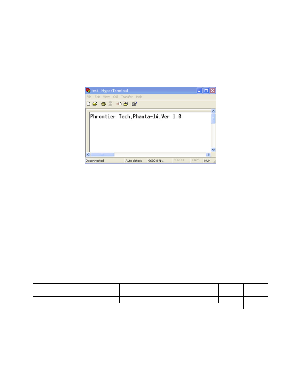
Step 7: This is an optional step for user’s convenience. In the Hyper Terminal window, click
Figure 7. Settings of the COM port property for the Hyper Terminal
on File >> Properties >> Settings >> ASCII setup. On the ASCII sending options,
select both options as shown in Figure 8.
PHANTA User Manual V1.4
Page 13
13
Figure 8. ASCII Settings for Hyper Terminal.
SR address
Bit 7
Bit 6
Bit 5
Bit 4
Bit 3
Bit 2
Bit 1
Bit 0
<IMG>
1 1 1 1 0 0 1
1
<SCC>
0 0 1 1 0 0 0
0
<CFG>
Reserved and set to 0 by default
1
Step 8: Power on the PHANTA box.
After powering up the PHANTA box, the window should display the model and software version
installed in the module like the one shown in Figure 9. This means the RS232 communication
between the module and computer is successfully established.
Figure 9. Starting message when RS232 communication is successfully established.
6.2.5 Programming Examples Using Hyper Terminal
This section is to give users an example on how to set PHANTA-S1F4 module to the desired
configuration. Assuming four Full configuration frame grabbers are connected to PHAN TA and
our goal is to:
1. Change the control method from DIP switch to RS232.
2. Activate image data output on port 1, 2, 5, 6, 7 and 8 (frame grabber 1, 3 and 4) and disable
port 3 and 4 (frame grabber 2).
3. Set frame grabber 4 (port 7) responsible for serial communication.
4. Set frame grabber 1 (port 1) responsible for camera control.
5. Write the new settings to memory.
The desired settings will have the binary settings in three shift registers as shown below:
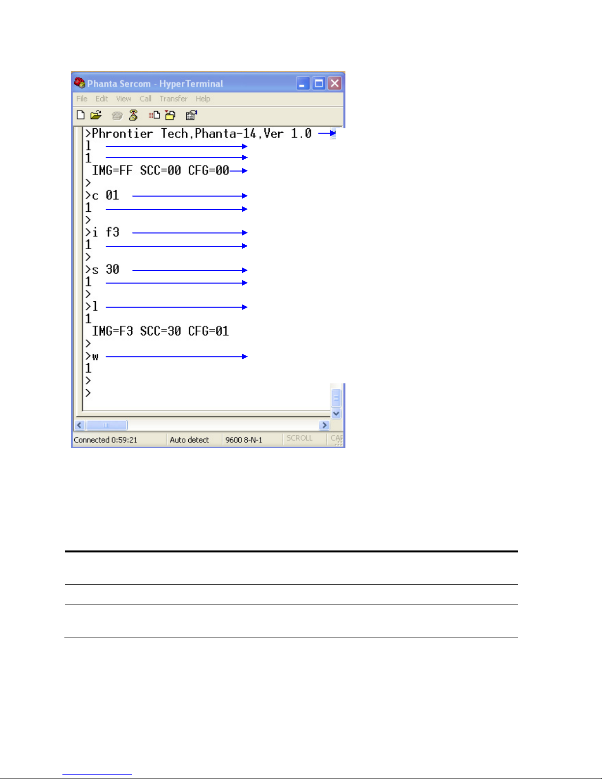
The step-by-step screen shot from using the Hyper Terminal to program the module is shown
below.
PHANTA User Manual V1.4
Page 14
14
LED name
ON
OFF
Blinking
Power Out
PWR2 is set to output
DC power
PWR2 is set as
alternative DC input
Not applicable
Power In
12V DC input good
12V DC input failure
Not applicable
RS232/
system error
RS232 control active
DIP switch control
active
System initialization
error
Use command “l” to list current settings.
Starting message when power up Phanta-14
This “1” means the command is valid.
Shows current settings for all shift registers.
Use command “c” to set <CFG> for RS232 control.
“1” confirms valid command and RS232 LED should turn on.
Use command “i” and corresponding hex number to set <IMG>.
“1” confirms valid command and LED will change accordingly.
Use command “s” and corresponding hex number to set <SCC>.
“1” confirms valid command and LED will change accordingly.
Use command “l” again to confirm changes in settings.
Use command “w” to write the current configuration into flash
memory.
7. LED Indicators
The indication of the 1x3 LED next to the power connector is defined in table 4.
The 3x8 LED array is used to show the status of the Camera Link signal routing. When the LED
is ON, it indicates the active ports for the corresponding image signals, control signals and serial
communication ports.
PHANTA User Manual V1.4
Table 4. Definition of the 1x3 LED indicator
Page 15
15
8. Specifications
8.1 General Specification
Operating Case Temperature 0 ~ 70 oC
Input Voltage DC 10 ~ 24 V
Supply Current Typical 0.3A @12V
Typical Power Consumption 3.6W @ 25 oC
AC/DC Power Supply 12V DC, 0.85A with Switchcraft 760BK locking plug
8.2 Camera Link Interface
Pixel Clock 20 to 85MHz
Configuration Base/Medium/Full
Image Enables FVAL, LVAL, DVAL, spare
Camera Control CC1, CC2, CC3, CC4
Communication SerTC, SerTFG
Connector Type MDR26 receptacle
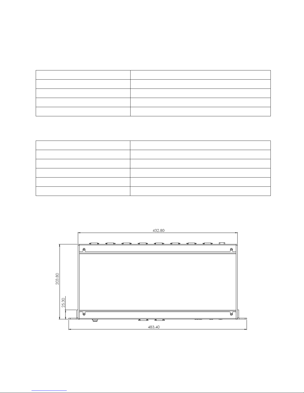
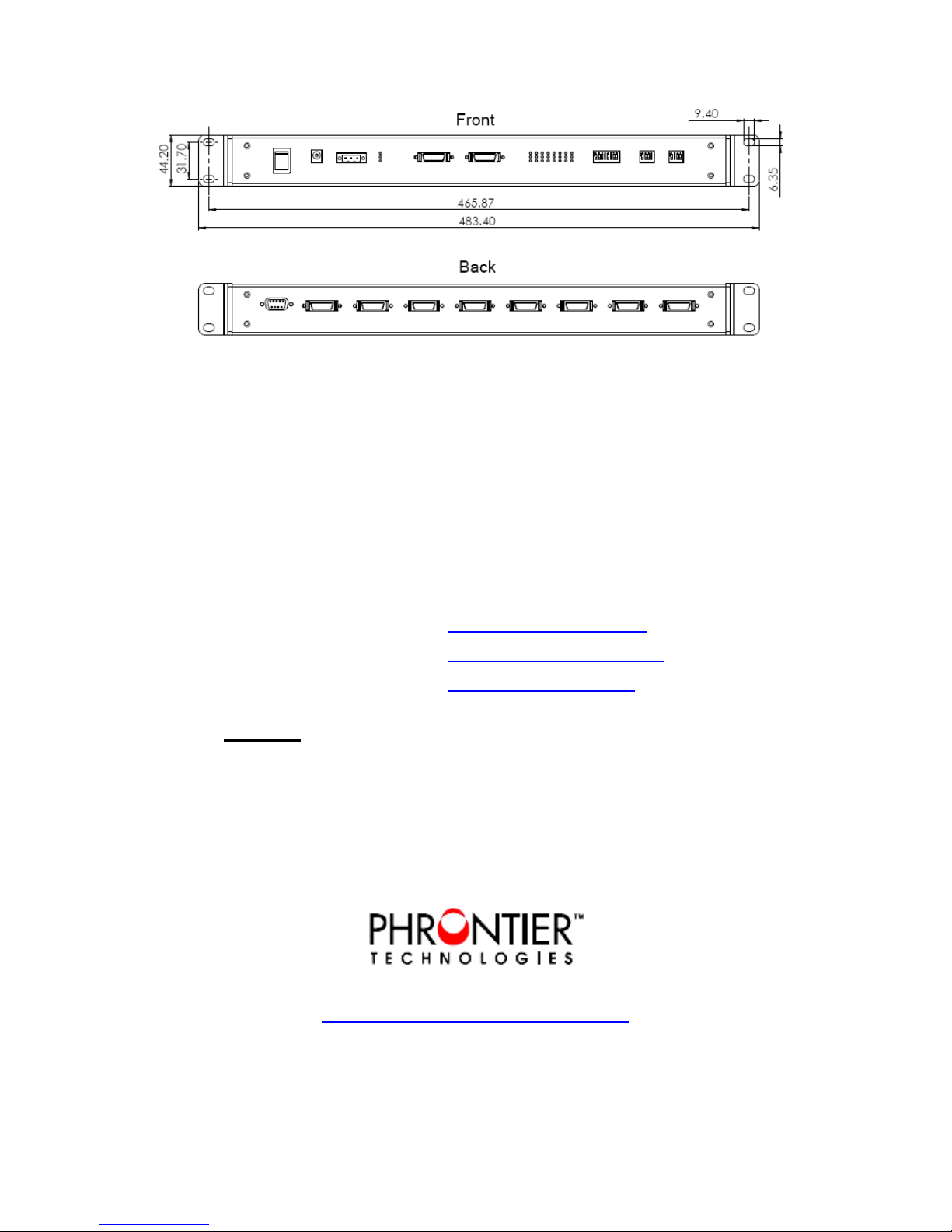
8.3 Mechanical Dimensions (mm)
PHANTA User Manual V1.4
Page 16
16
9. Conta ct Us
Thank you for purchasing Phrontier products. We hope you enjoy all the benefits brought to you
by the unique design and functionalities. If you need any assistance, please contact your
distributor.
You may also contact us via:
Phone: 866-389-2829 (Toll free for US and Canada)
Direct: +1 949-305-6622
Fax: +1 801-998-1855
Emails: For sales:
For technical support:
For all other inquiries:
Mail: US Office
Phrontier Technologies, LLC.
26471 Rancho Parkway South, Suite A
Lake Forest, CA 92630
USA
www.phrontier-tech.com
[email protected]
Toll Free: 1-866-389-2829
PHANTA User Manual V1.4
 Loading...