

Page 1
P4S-342 User Manual > Introduction
2017-12-06 Sollae Systems page 1 of 17
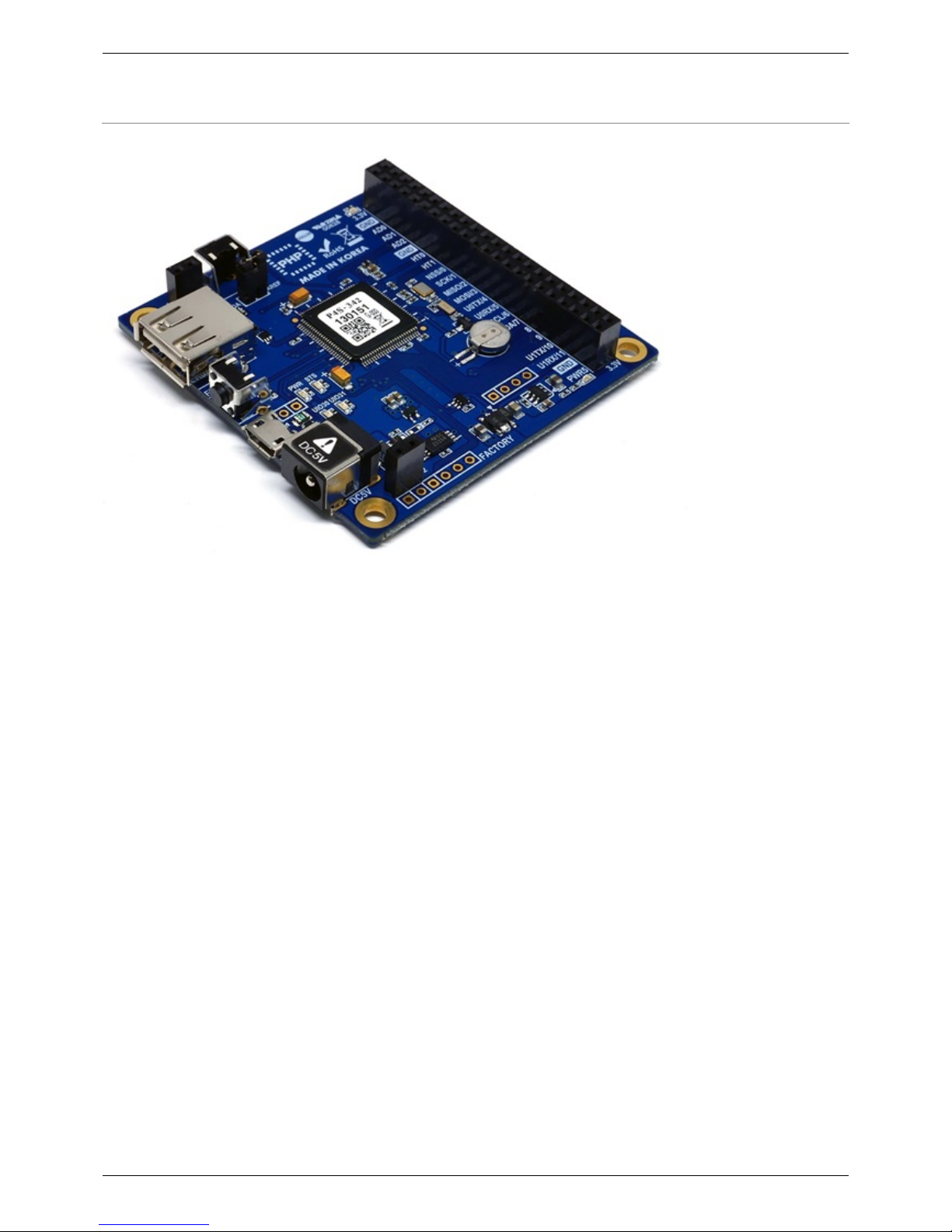
Overview
P4S-342 is an industrial programmable I/O board. You can build various network communication
systems connecting P4S-342 to many devices such as sensors and actuators. We provide a selfdevelopment programming language, which is called PHPoC, for programing P4S-342. This language
is easy to use and compatible with PHP which is widely used script language.
※ PHPoC is basically compatible with PHP but those languages are not the same because of
restrictions about embedded system. Refer to the PHPoC Language Reference and PHPoC vs PHP for
detailed information.
Page 2

P4S-342 User Manual > Features
2017-12-06 Sollae Systems page 2 of 17
Features
Provides Self-Development PHPoC Interpreter
Provides simple development environment via USB
Provides IEEE802.11b/g Wireless LAN
Provides 22 digital i/o and 6 analog input ports
Provides 2 UART ports
Provides 4 hardware timer
Provides I2C and SPI interfaces
Provides TCP/IP stacks
Provides a Web Server
Support Websocket, Telnet, SSH, SSL
Provides the various libraries such as Email, DNS, MySQL and so on
Provides PHPoC Debugger - a development tool for Windows
Page 3
P4S-342 User Manual > H/W Specification
2017-12-06 Sollae Systems page 3 of 17
H/W Specification
Power
Input 1 DC 5V (±0.5V)
Input 2 DC 5V (±0.5V) - USB Device Port
Current
Consumption
Typical - about 85mA(※ without USB WLAN adapter)
Power Down mode - less than 200uA
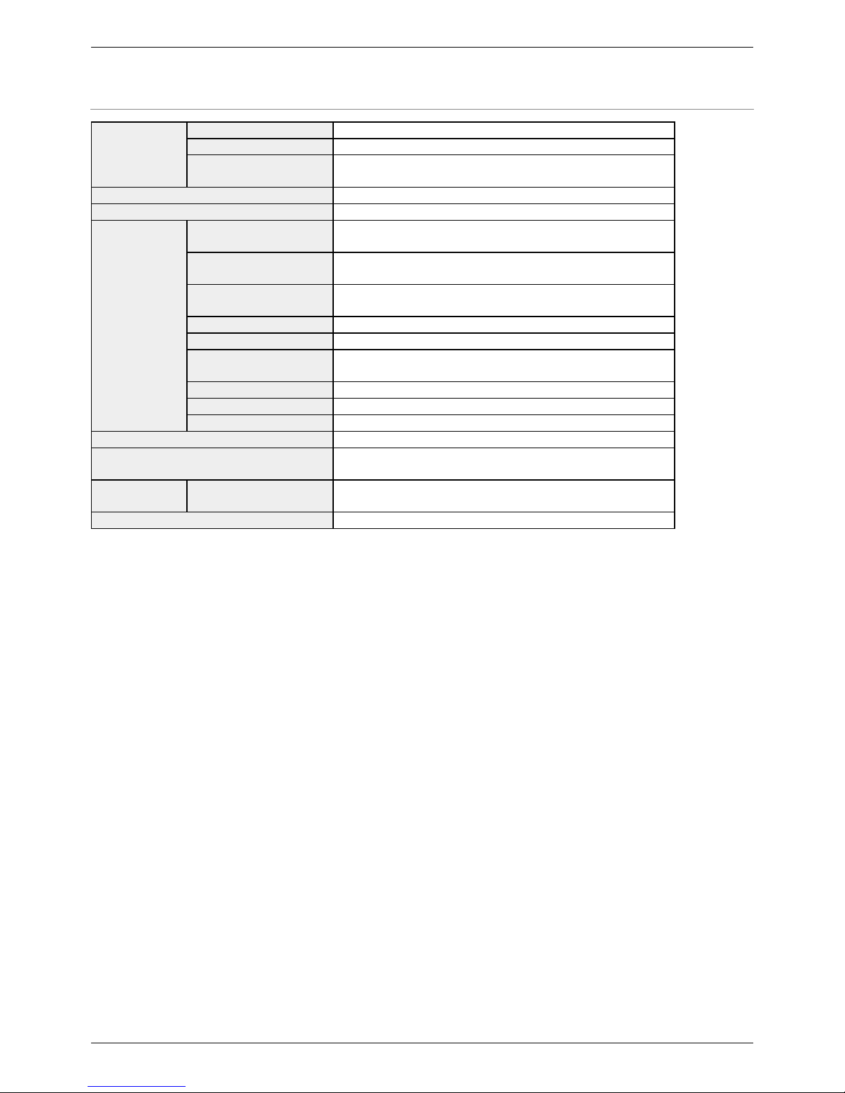
Dimension 66.5mm x 63.8mm x 13mm
Weight about 27g (without USB WLAN adapter)
Interface
UART
2 X UART Ports(UART0 ~ 1),
Baudrate: 1,200 bps ~ 230,400 bps
Network
IEEE802.11b/g Wireless LAN (require Ralink
RT3070/5370 chipset Wireless LAN Adapter)
USB
USB Host - for WLAN adapter
USB Device - for PC
Digital I/O UIO0: pin #0 ~ #21, #30(LED), #31(LED)
Analog Input ADC_CH0 ~ 5, AREF, 12-bit resolution
Hardware Timer (HT)
HT0 ~ 3, toggle/pulse/pwm output and
capture mode
SPI NSS, SCK, MISO, MOSI
I2C SCL, SDA
SPC STX, SRX, SRO
Internal Battery 3V(rechargeable)
Wireless LAN Security
WPA-PSK / WPA2-PSK,
WPA-Enterprise(TLS/TTLS/PEAP)
Temperature
Storage
/Operating
-20℃ ~ 60℃
Environment RoHS Compliant
Page 4
P4S-342 User Manual > Dimension
2017-12-06 Sollae Systems page 4 of 17
Dimension
※ Dimensions(unit : mm) may vary according to a method of measurement.
Page 5
P4S-342 User Manual > Layout
2017-12-06 Sollae Systems page 5 of 17
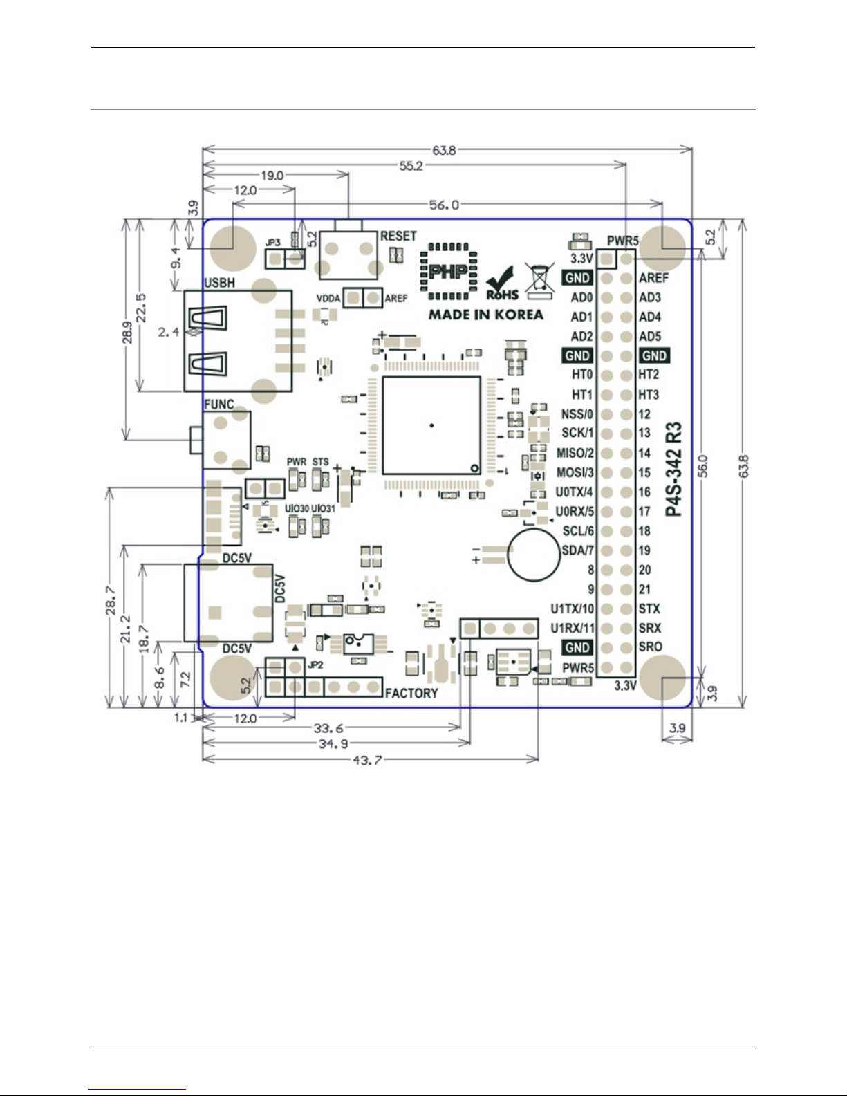
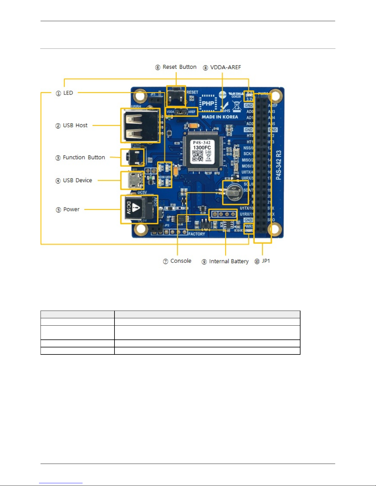
Layout
1. LED
There are six LEDs on the P4S-342 board.
LED Action
PWR / 3.3V / PWR5 supplying power > ON
STS
running PHP > repeat On and Off in every second
not running PHP > briefly blinks 1 time at a time
UIO30 on board LED: connected with 30th pin of UIO0
UIO31 on board LED: connected with 31th pin of UIO0
※ PWR, STS, UIO30 and UIO31 are also located on the opposite side.
2. USB Host Port for Connection with WLAN adapter
P4S-342 provides a USB host port for an USB WLAN adapter. You can connect P4S-342 to Wireless
LAN by connecting an WLAN adapter to this port.
※ Caution: Only adapters using Ralink RT3070/5370 chipsets are available.
Page 6
P4S-342 User Manual > Layout
2017-12-06 Sollae Systems page 6 of 17
3. Function Button (Func)
The function button is used for changing mode to the Button setup mode.
4. USB Device Port for connection with PC
The USB device port is to connect with PC. You can access to P4S-342 via development tool by
connecting USB cable to this port. You can supply DC 5V power through this port. However,
P4S-342 may not work properly in case of supplying power via this port only due to insufficient
current.
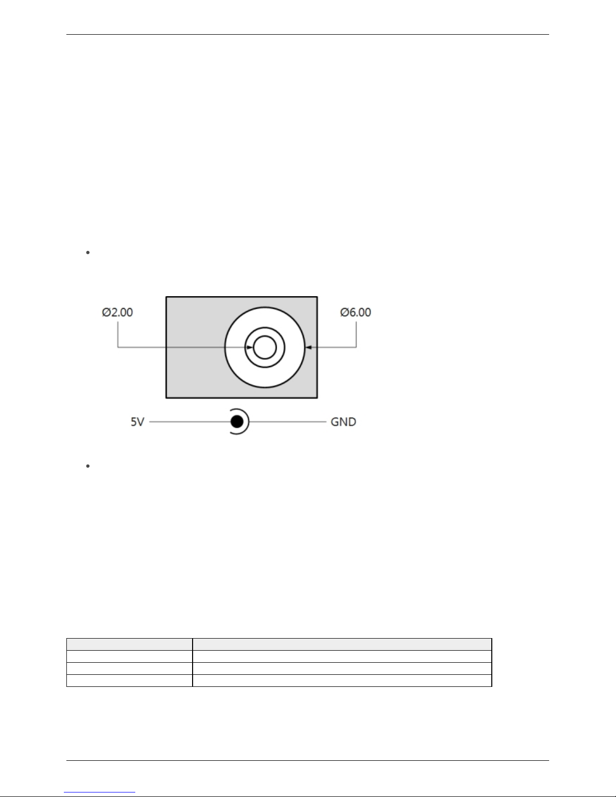
5. Supplying Power
DC 5V Input
This port is the main input port for supplying power. Specification is as follows:
USB Device port (Micro USB)
This port can be a sub input port for supplying power.
6. Reset Button (RESET)
This button is used for hardware reset.
7. Console Port
This port is console port for management.
Division Value
Signal Level 3.3V
Configuration 115,200bps / 8 Data bit / 1 Stop bit / No parity
Pin Assignment #1 - 3.3V, #2 - RX, #3 - TX, #4 - GND
Page 7
P4S-342 User Manual > Layout
2017-12-06 Sollae Systems page 7 of 17
8. JP1
Label Description Label Description
3.3V 3.3V Output PWR5
Output Supplied Power
(5V±0.5V)
GND Ground AREF ADC reference input port
AD0 ADC channel 0 AD3 ADC channel 3
AD1 ADC channel 1 AD4 ADC channel 4
AD2 ADC channel 2 AD5 ADC channel 5
GND Ground GND Ground
HT0 Hardware Timer 0 HT2 Hardware Timer 2
HT1 Hardware Timer 1 HT3 Hardware Timer 3
NSS/0 SPI - NSS / UIO0 #0 12 UART #1 RTS / UIO0 #12
SCK/1 SPI - SCK / UIO0 #1 13 UART #1 CTS / UIO0 #13
MISO/2 SPI - MISO / UIO0 #2 14 UIO0 #14
MOSI/3 SPI - MOSI / UIO0 #3 15 UIO0 #15
U0TX/4 UART #0 TX / UIO0 #4 16 UIO0 #16
U0RX/5 UART #0 RX / UIO0 #5 17 UIO0 #17
SCL/6 I2C - SCL / UIO0 #6 18 UIO0 #18
SDA/7 I2C - SDA / UIO0 #7 19 UIO0 #19
8 UART #0 RTS / UIO0 #8 20 UIO0 #20
9 UART #0 CTS / UIO0 #9 21 UIO0 #21
U1TX/10 UART #1 TX/ UIO0 #10 STX SPC TX
U1RX/11 UART #1 RX/ UIO0 #11 SRX SPC RX
GND Ground SRO SPC Reset
PWR5
Output Supplied Power
(5V±0.5V)
3.3V 3.3V Output
9. VDDA-AREF
If you connect this port, 3.3V is supplied to the analog input reference port (AREF).
10. Internal Battery
Internal battery is for saving log messages and operating RTC. Specification of this battery is as
follows:
Parameter Value
Capacity 5.8mAh
Nominal Voltage DC 3V
Charge Voltage DC 2.8V ~ 3.1V
※ Refer to the datasheet for more information about the battery
Page 8

P4S-342 User Manual > Peripherals(JP1)
2017-12-06 Sollae Systems page 8 of 17
Peripherals (JP1)
Analog Input: ADC
P4S-342 provides 6 ADC input channels.
To use the ADC, the reference voltage input is required. When VDDA-AREF jumper is connected,
3.3V is connected to the reference voltage input pin.
※ VDD-AREF jumper is connected on the P4S-342 when shipped from the factory.
When directly inputting the reference voltage without using JP4, input it with the AREF pin.
※ Caution: Inputting a voltage to the AREF pin while the VDDA-AREF jumper is connected may
cause the product to malfunction. Therefore, before connecting the voltage to the AREF pin, make
sure that the jumper is NOT connected.
Specification of an ADC port is as follows:
Parameter Value
Resolution 12 bits (0 ~ 4095)
Input Type DC Voltage (Max. 3.3V)
Number of Channel 6 channels
Interfaced Pin Label AREF, AD0 ~ 5
Hardware Timer: HT
P4S-342 provides 4 hardware timers called HT.
Specification of HT is as follows:
Parameter Value
Mode Output mode(toggle, pulse, PWM), Capture mode
Unit ms(millisecond) or us(microsecond)
Number of Channel 4 channels
Interfaced Pin Label HT0 ~ 3
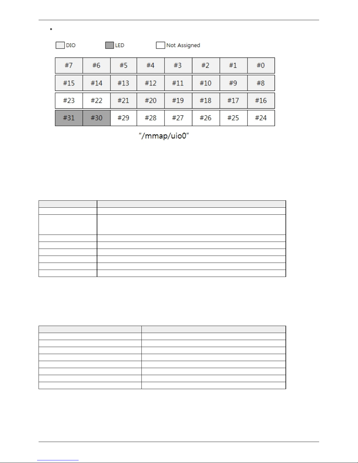
Digital Inputs/Outputs: UIO
P4S-342 provides 24 digital I/O ports including 22 universal I/O ports (numbered 0 to 21) and 2 LED
ports (numbered 30 and 31). Two LEDs on board are assigned to number 30 and 31. The pins
numbered 0 to 21 can be available to be set digital input or output but note that pins which are
shared with serial interfaces (numbered 0 to 13) cannot be available to use a digital input or output
while they are being used by the serial communication (UART, SPI and I2C).
Electrical Characteristics of Digital I/O
Parameter Description Min.[V] Max.[V] Current
V
IH
HIGH level input 2.31 - -
V
IL
LOW level input
0
0.99 -
V
OH
HIGH level output 2.4 - +8mA
V
OL
LOW level output
0
0.4 +8mA
Page 9
P4S-342 User Manual > Peripherals(JP1)
2017-12-06 Sollae Systems page 9 of 17
Pin Assignment of Digital I/O
Serial: UART
P4S-342 provides 2 UART ports.
Specification of UART is as follows:
Division Value
Number of Port 2
Interfaced Pin Label
UART0: Required(U0TX/4, U0RX/5, GND), Optional(U0RTS/8, U0CTS/9)
UART1: Required(U1TX/10, U1RX/11, GND), Optional(U1RTS/12,
U1CTS/13)
Signal Level 3.3V
Baud Rate 1,200 ~ 230,400 [bps]
Parity NONE / EVEN / ODD / MARK / SPACE
Data bit 8 / 7(Parity is required to use 7 data bit mode)
Stop bit 1 / 2
Flow Control NONE, RTS/CTS
Serial: SPI
P4S-342 provides a SPI interface.
Specification of SPI is as follows:
Parameter Value
Number of Port 1
Signal Level 3.3V
Interfaced Pin Label NSS/0, SCLK/1, MOSI/2, MISO/3
SPI mode mode 0 ~ 3
Bit Order LSB > MSB or MSB > LSB
Transmission Unit 8bit or 16bit
Basic Clock Speed 42㎒
Frequency 2 / 4 / 8 / 16 / 32 / 64 / 128 / 256
Page 10

P4S-342 User Manual > Peripherals(JP1)
2017-12-06 Sollae Systems page 10 of 17
Serial: I2C
P4S-342 provides an I2C interface.
Specification of I2C is as follows:
Parameter Value
Number of Port 1
Signal level 3.3V
Interfaced Pin Label SCL, SDA
Data Rate Standard mode(100Kbps) or Fast mode(400Kbps)
Address Type 7bits
Smart expansion Procedure Call: SPC
P4S-342 provides an SPC interface for communication with smart expansion boards.
Specification of SPC is as follows:
Parameter Value
Number of Port 1
Signal level 3.3V
Interfaced Pin Lable STX, SRX, SRO
※ Refer to the PHPoC Device Programming Guide for p40 for detailed information about
peripherals.
Page 11
P4S-342 User Manual > How to Use > Software(IDE)
2017-12-06 Sollae Systems page 11 of 17
Software (IDE)
PHPoC Debugger
PHPoC Debugger is a software used for developing and setting PHPoC products. You need to install
this program on your PC for using PHPoC.
Download PHPoC Debugger
PHPoC Debugger Manual
Functions and Features of PHPoC Debugger
Upload files from local PC to PHPoC
Download files in PHPoC to local PC
Edit files stored in PHPoC
Debug PHPoC scripts
Monitor resources of PHPoC
Configure parameters PHPoC
Upgrade Firmware of PHPoC
Support MS Windows O/S
Page 12

P4S-342 User Manual > How to Use > Connecting
2017-12-06 Sollae Systems page 12 of 17
Connecting Product
Connect the USB device port of P4S-342 to your PC via a USB cable.1.
Run PHPoC Debugger2.
Download PHPoC Debugger
PHPoC Debugger Manual
Select connected COM PORT and press connect ( ) button.3.
If USB is successfully connected, connect button will be inactivated and disconnect button (4.
) will be activated
Page 13

P4S-342 User Manual > How to Use > Reset
2017-12-06 Sollae Systems page 13 of 17
Reset
Settings Reset
Settings Reset makes all settings of your PHPoC products to factory default.
A certificate in PHPoC is also deleted.
Settings Reset Procedure
Step Action Product State STS LED
1
Press function button shortly (less than 1
second)
Button setup mode On
2
Keep pressing the function button over 5
seconds
Preparing initialization
Blink very
rapidly
3 Check if the STS LED is turned OFF Initialization ready Off
4
Release the function button right after the
STS is OFF.(※ If you don't release the
button within 2 seconds, the state go back
to the step 3)
Progressing
initialization
On
5 Rebooting automatically Initial state Off
Factory Reset
Factory Reset makes all settings of your PHPoC products to factory default including a password.
Futhermore, all files stored in flash memory are deleted as well as certificate. Because of this, you
have to backup your files before doing Factory Reset.
Factory Reset Procedure
Page 14

P4S-342 User Manual > How to Use > Web Interface
2017-12-06 Sollae Systems page 14 of 17
Web Interface
PHPoC itself has a webserver to provide a web interface. When receiving a HTTP request, it executes
the php script in the requested file (if there) and respond to the client. Webserver is independent of
PHPoC main script. TCP 80 is used for web server and you can use the interface via Internet Explorer,
Chrome or any other web browsers.
How to use web interface
To use the web interface, "index.php" file should be in the file system of P4S-342. Connect to this
page by entering device IP address after connecting it to network.
If the name of file is not "index.php", just specify the name of file after the IP address with slash
mark.
Practical Use of Web Interface
Since the web server executes the php script in the requested file, user can put php code in the in
the requested file to interact with peripherals such as I/O port, I2C, SPI, UART, ADC and so on.
It is worth noting that there is other way to interact with the peripherals in real-time from web
interface. This can be done by using websocket.
A web interface is very useful because it runs even a state which is activating Simple WLAN
Connection function. If you upload web pages for specific functions, you can easily use them
through wireless LAN.
Page 15
P4S-342 User Manual > How to Use > Simple WLAN Connection
2017-12-06 Sollae Systems page 15 of 17
Simple WLAN Connection
P4S-342 enters into Button Setup Mode when you push function button in normal state. In this
mode, Simple WLAN Connection function is activated if an USB WLAN adapter is connected so you
can access to P4S-342 by smartphone or laptop by WLAN.
※ Only the task for not basic task but web interface runs in the Button Setup Mode.
※ Simple WLAN Connection function is available by connecting a USB WLAN adapter.
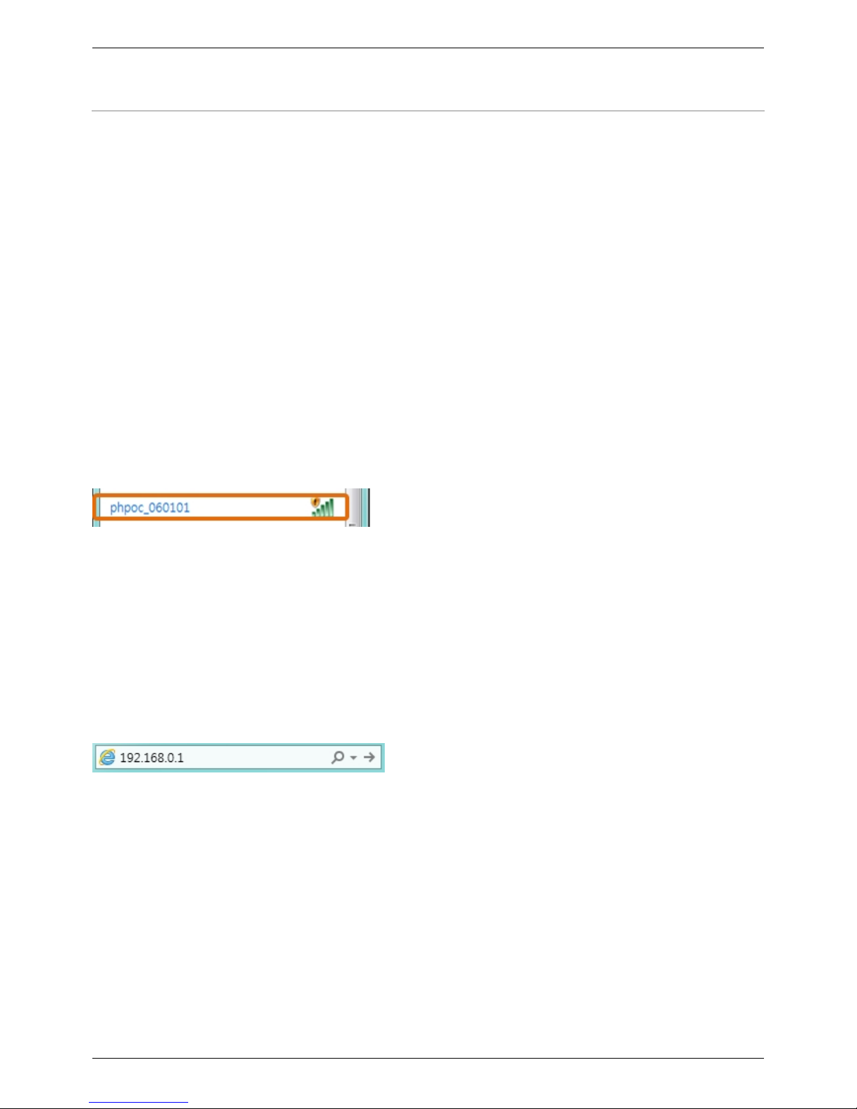
SSID
Once WLAN Easy Connect function is activated in the Button setup mode, P4S-342 uses SSID
including its own MAC address like an AP. SSID is contained the second half of the P4S-342's MAC
address after "phpoc_" which is a prefix.
For example, if the MAC address is "0030f9060101", the SSID is "phpoc_060101".
WLAN Connection
Find the SSID of P4S-342 via a smartphone or laptop.
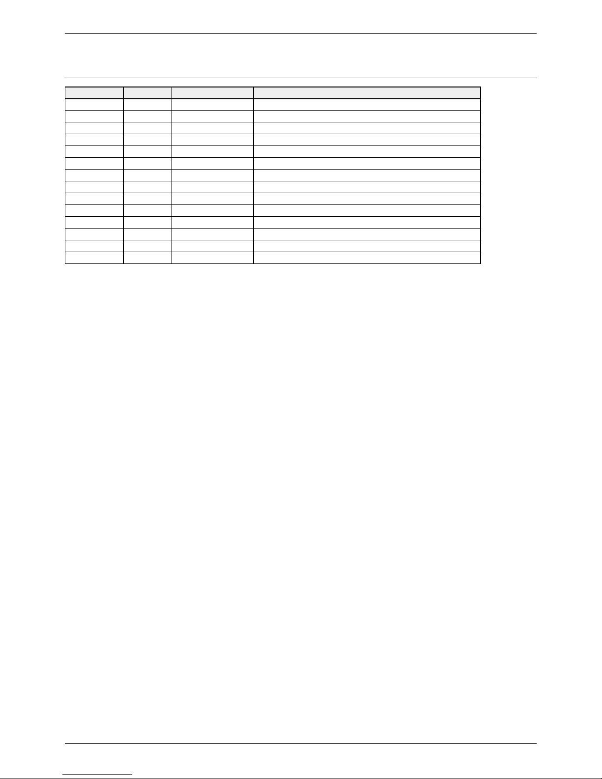
DHCP
While using WLAN Easy Connect function, a mobile automatically gets a dynamic IP address from
your P4S-342. The IP address of P4S-342 is fixed to 192.168.0.1 and mobile obtains an IP address in
192.168.X.X range.
Access to Product
After uploading a setting page to P4S-342, you can access to it by web browser.
Page 16

P4S-342 User Manual > How to Use > Escaping Infinite Reset
2017-12-06 Sollae Systems page 16 of 17
Escape Infinite Reset
PHPoC basically runs scripts when it boots up. Therefore, it is possible that a P4S-342 cannot be
escaped from infinite reboot when script contains system command such as "reboot". To solve this
problem, it is required to stop the running script.
Refer to the following.
Entering ISP mode1.
Make P4S-342 to enter ISP mode by supplying power while pressing FUNC button. In the ISP
mode, you can access to PHPoC by PHPoC Debugger without running a script.
Connect to PHPoC2.
Connect a PC to PHPoC via a USB cable and connect to the port via PHPoC Debugger. A
message window related with ISP mode will be popped up.
Reboot PHPoC3.
Reboot PHPoC by using "Reboot a product" menu in PHPoC Debugger. After rebooting,
PHPoC stops running script even it is not in the ISP mode.
Correct source code4.
Correct the source code to prevent infinite reboot state.
Page 17
P4S-342 User Manual > Device Information
2017-12-06 Sollae Systems page 17 of 17
Device Information
Device Channel Path Note
UART 2 /mmap/uart0~1 NET 1 /mmap/net1 TCP 5 /mmap/tcp0~4 UDP 5 /mmap/udp0~4 Digital I/O 1 /mmap/uio0 pin #0 ~ #21, #30, #31
ADC 2 /mmap/adc0~1 ST 8 /mmap/st0~7 HT 4 /mmap/ht0~3 SPI 1 /mmap/spi0 I2C 1 /mmap/i2c0 RTC 1 /mmap/rtc0 UM 4 /mmap/um0~3 NM 1 /mmap/nm0 SPC 1 /mmap/spc0 -
※ Refer to the PHPoC Device Programming Guide for p40 for detailed information about using
devices.
 Loading...