


FASTCAM Nova
Hardware Manual

The copyright of this manual is held by PHOTRON LIMITED.
Product specifications and manual contents are subject to change without notice.
PHOTRON LIMITED bears no responsibility for any results by using our products nor by applying this manual to any operations.
WARNING
This equipment has been tested and found to comply with the limits for a Class A digital device,
pursuant to part 15 of the FCC Rules. These limits are designed to provide reasonable protection
against harmful interference when the equipment is operated in a commercial environment. This
equipment generates, uses, and can radiate radio frequency energy and, if not installed and used in
accordance with the instruction manual, may cause harmful interference to radio communications.
Operation of this equipment in a residential area is likely to cause harmful interference in which case
the user will be required to correct the interference at his own expense.
CAUTION:
Any changes or modifications not expressly approved by the party responsible for compliance could
void the user's authority to operate the equipment.

Introduction
Introduction
Thank you for your purchase of Photron’s high-speed camera system, the “FASTCAM NOVA”
(referred to below as the system).
This manual contains the operating instructions and warnings necessary for using the system.
Before using the system, please read the entire manual.
If any part of this manual is unclear, contact Photron using the contact information printed at
the back of the manual.
After you finish reading the manual, store it in a safe place along with the warranty card and
refer back to it when necessary.
Using the Manual
Using the Manual

Using the Manual
Using the Manual
This section explains the layout of the manual.
Introduction
The introduction explains the manual and safety precautions.
Chapter 1, Setup
This chapter gives an overview of the components that make up the system. It also explains basic keypad
operation and a list of items that should be checked before using the system.
Chapter 2, Recording
This chapter explains operations related to recording.
Chapter 3, Product Specifications
This chapter explains the system’s specifications.
Chapter 4, Product Specifications
This chapter explains about the warranty.
Chapter 5, Contacting Photron
This chapter lists the contact information to use when contacting Photron if the system malfunctions or if a
portion of the manual is unclear.

Manual Notation
Manual Notation
The following icons and symbols are used in the explanations in this manual.
Icon/Symbol
Description
This symbol indicates supplementary items to be aware of
when using the software.
This symbol indicates the location of a reference.
This symbol indicates content that should always be read.
This symbol indicates instructions that should always be
followed when using the software, or things to be careful of
when using the software.
" "
This symbol is used to indicate the names of items on a
screen, references, dialog names, and connectors.
[ ]
This symbol is used to indicate menu names, and
sub-menu names.

Using the System Safely and Correctly
Using the System Safely and Correctly
In order to prevent injury to yourself and others, and to prevent damage to property, carefully
observe the following safety precautions.
Photron has given its full attention to the safety of this system. However, the extent of damage
and injury potentially caused by ignoring the content of the safety precautions and using the
system incorrectly is explained next. Please pay careful attention to the content of the safety
precautions when using the system.
This symbol indicates actions that carry the risk that a person could receive a
serious injury.
This symbol indicates actions that carry the risk that a person could receive a
moderate injury, or that damage to physical property might occur.
The safety precautions to be observed are explained with the following symbols.
This symbol indicates actions that require caution.
This symbol indicates actions that are prohibited and must be avoided.
This symbol indicates actions that must always be performed.
Caution
Warning

Using the System Safely and Correctly
■Do not perform actions that will damage the AC cable or plug.
(Do not damage the cable, modify it, use it near a heater, excessively bend, twist or pull
on it, place heavy objects on it, or bundle it.)
Using the cable when damaged can cause fire, electric shock, or a short circuit.
■Do not use the system in a manner which will exceed the rating of the power outlet
or wiring equipment used.
Exceeding the power rating might cause a fire from excessive heat.
■Do not insert metallic objects inside, or pour liquids such as water on, the system.
Doing so can cause fire, electric shock, or malfunction from short circuit or heat.
■Do not disassemble or modify the system.
There are high voltages inside the system that can cause electric shock.
■Do not plug in or unplug the power cord with wet hands.
Doing so can cause electric shock.
■Make sure the power plug is fully insert into the socket
Not fully plugging in the power cable can cause fire from electric shock or heat.
■When something is wrong with the system, unplug the power cable immediately.
- When a foreign substance or liquid, such as metal or water, gets inside.
- When the outer case is broken or damaged, such as from a fall.
- When the system produces smoke, a strange smell, or strange sound.
Using the system in these conditions might cause a fire or electric shock.
■Do not use the accessories by the usage that a manufacturer does not specify. It may
cause damage of protection.
Warning

Using the System Safely and Correctly
■Always unplug the system when cleaning it or when it is unused for a long period of
time. Leaving or storing the system connected to the power source might cause fire
from insulation deterioration or electrical discharge.
■Please consult us in advance when you perform an event by which laser light or direct
rays fall on the image sensor surface.
■Do not set the system in a location where the temperature gets unusually hot.
The trunk and inside of a car can get especially hot in summer.
Doing so can cause the outer case and internal components to deteriorate or cause a
fire.
■Do not place the system in a location prone to oily smoke or steam, or in a location
with a lot of humidity or dust.
Oil, moisture, and dust conduct electricity, which can cause a fire or electric shock.
■Ambient temperature 0-45°C, humidity 80% RH or lower, maximum altitude 2,000m
or lower. In addition, if exceeding these limits, use in a condensation-free environment.
Use in a condition out of the above limits can cause malfunction.
■Do not store the equipment in a location where the temperature goes below -20°C or
higher than 60°C. Also, prevent condensation from forming during shipment.
■When shipping, remove the connecting cable and use the original packaging or a
dedicated carrying case.
Do not ship the equipment in an environment where the temperature goes below -20°C
or higher than 60°C. Also, prevent condensation from forming during shipment.
Caution

Using the System Safely and Correctly
■This system has a handle, but this assumes use of camera installation and
transportation.
When recording, please fix the equipment using a stand, tripod, etc and do not record
with the handle being carried.
■When installing the camera with a tripod, please check the tripod load capacity and
be careful not to exceed the load bearing capacity.
Also, when using a tripod, please make sure that the tripod, tripod screw, panhead, and
others are properly set, and be careful not to fall down the tripod.
■Although this camera is compatible with outdoor use, the AC power supply unit is not
outdoor compatible. When using it outdoors, prepare another power supply.
Caution

Using the System Safely and Correctly
“CE” mark indicates that this product complies with the European requirements for safety,
health, environment and customer protection. “CE” mark equipments are intended for sales in
Europe.
These symbols indicate that this product is not to be disposed of with your household
waste, according to the WEEE Directive (2002/96/EC), the Battery Directive
(2006/66/EC) and/or your national laws implementing those Directives.
This product should be handed over to a designated collection point, e.g., on an
authorized one-for-one basis when you buy a new similar product or to an authorized
collection site for recycling waste electrical and electronic equipment (EEE) and
batteries and accumulators. Improper handling of this type of waste could have a
possible impact on the environment and human health due to potentially hazardous
substances that are generally associated with EEE. Your cooperation in the correct
disposal of this product will contribute to the effective usage of natural resources.
For more information about the recycling of this product, please contact your local city
office, waste authority, approved scheme or your household waste disposal service or
visit www.photron.com.
(EEA: Norway, Iceland and Liechtenstein)
This product is in conformity with the protection requirements of EU Council Directive
2014/30/EU (Class A) on the approximation of the laws of the Member States relating
to electromagnetic compatibility.
Warning: This is a Class A product. In a domestic environment, this product may cause
radio interference, in which case the user may be required to take adequate measures.
European Union (and EEA) only

Using the System Safely an
d Correctly
Electrostatic Discharge (ESD) events may cause immediate and unrecoverable damage to the image sensor.
Please read the following instructions and take EXTREME CARE when cleaning the image sensor surface.
■ALWAYS take appropriate anti-static precautions when cleaning or working near the
Image sensor.
■DO NOT use any form of cleaning equipment using electrostatic or ‘charged fiber’
technology.
◼ Please discharge any electrostatic build up in your body by touching a grounded
metallic surface before working near the camera sensor.
◼ Very gently, use only clean and dry air to remove dust from surface of the image
sensor.
◼ To remove stubborn contamination use the highest grade (e.g. VLSI grade) pure
Isopropyl alcohol (IPA) with optical wipes of ‘clean room’ grade.
◼ Extreme care must be taken! Gently wipe across the sensor in a single action.
(DO NOT rub to avoid abrasive damage to delicate optical coatings on the glass
surface.)
Cleaning of the Image Sensor Surface

Contents
Contents
Capter 1 Setup 1
1.1. About the System’s Components and Accessories ................................. 2
1.1.1. Components .......................................................................... 2
1.1.2. Accessories/Options ................................................................ 2
1.1.3. Type ..................................................................................... 3
1.2. Part Names .................................................................................... 4
1.2.1. Camera Body ......................................................................... 4
1.2.2. Camera Body Part Names ........................................................ 5
1.2.3. Interchangeable Lens Mount .................................................... 7
1.2.4. Status Display LEDs on the Rear of the Camera Body .................. 8
1.2.5. Power Supply Connector, DC Cable ........................................... 9
1.2.6. Gigabit Ethernet Connector .................................................... 11
1.2.7. EXT-SSD Connector .............................................................. 12
1.2.8. RESET Switch ...................................................................... 13
1.3. Input / Output Signal Types ............................................................. 14
1.3.1. TRIG SW IN ......................................................................... 14
1.3.2. INPUT 1/2 ........................................................................... 15
1.3.3. IO INPUT Circuit Diagram ...................................................... 16
1.3.4. OUTPUT 1/2 ........................................................................ 17
1.3.5. Using External Synchronization Signals ................................... 18
1.3.6. Synchronization with a variable frequency ............................... 19
1.3.7. Signal Delay ......................................................................... 20
1.3.8. IRIG IN (External Time Synchronization) ............................... 22
1.3.9. IRIG-sync Operation ............................................................. 23
1.4. Device Connections ......................................................................... 24
1.4.1. Minimum Equipment Connection ............................................ 24
1.4.2. Connecting a Video Monitor ................................................... 25
Capter 2 Recording 29
2.1. Selecting Frame Rate/ Resolution ..................................................... 30

Contents
2.2. Selecting Shutter Speed .................................................................. 31
Capter 3 Product Specifications 32
3.1. Specifications ................................................................................ 33
3.1.1. Product Specifications .......................................................... 33
3.1.2. Random Reset Delay/ Dead Time ........................................... 34
3.1.3. Other Supported Function ..................................................... 35
3.1.4. General Specifications ........................................................... 36
3.1.5. Frame Rate and Resolution .................................................... 37
3.1.6. Shutter Speed List ................................................................ 43
3.1.7. Recordable Image Count/ Resolution ...................................... 44
3.1.8. Recordable Image Count/Resolution ....................................... 45
3.2. Dimensions .................................................................................... 46
3.2.1. Camera Body ....................................................................... 46
3.2.2. AC Power Supply Unit ........................................................... 54
Capter 4 Warranty 55
4.1. About the Warranty ........................................................................ 56
Capter 5 Contacting Photron 57
5.1. Contact Information ........................................................................ 58
A. Appendix エラー! ブックマークが定義されていません。
A.1. Reference Information ........... エラー! ブックマークが定義されていません。
A.1.1. Relative Spectral Response (monochrome)エラー! ブックマークが定義されていません。
A.1.2. Quantum Efficiency (monochrome)エラー! ブックマークが定義されていません。
A.1.3. Relative Spectral Response (color)エラー! ブックマークが定義されていません。
A.1.4. Quantum Efficiency (color)エラー! ブックマークが定義されていません。

1
Capter 1 Setup
This chapter gives an overview of the
components that make up the system. It
also explains a list of items that should be
checked before using the system.

2
FASTCAM Nova
1.1 About the System’s Components and Accessories
1.1. About the System’s Components and Accessories
1.1.1. Components
Refer to the attached packing list for this product's standard components and accessories.
1.1.2. Accessories/Options
The following options are available for the system.
1. Specialized Spear Power Supply Connector (for Custom Cable)
2. FASTCAM Nova Specialized Carrying Case
3. Specialized Canon EF Remote Control Mount
4. Specialized FAST Drive Holder
5. FAST Drive Cable (30cm)
6. FAST Drive 1TB
7. FAST Dock
Use only the components and accessories/options specified on the”1.1.About the
System’s Components and Accessories” for AC power adapter/AC cable and others.
3
FASTCAM Nova
1.1 About the System’s Components and Accessories
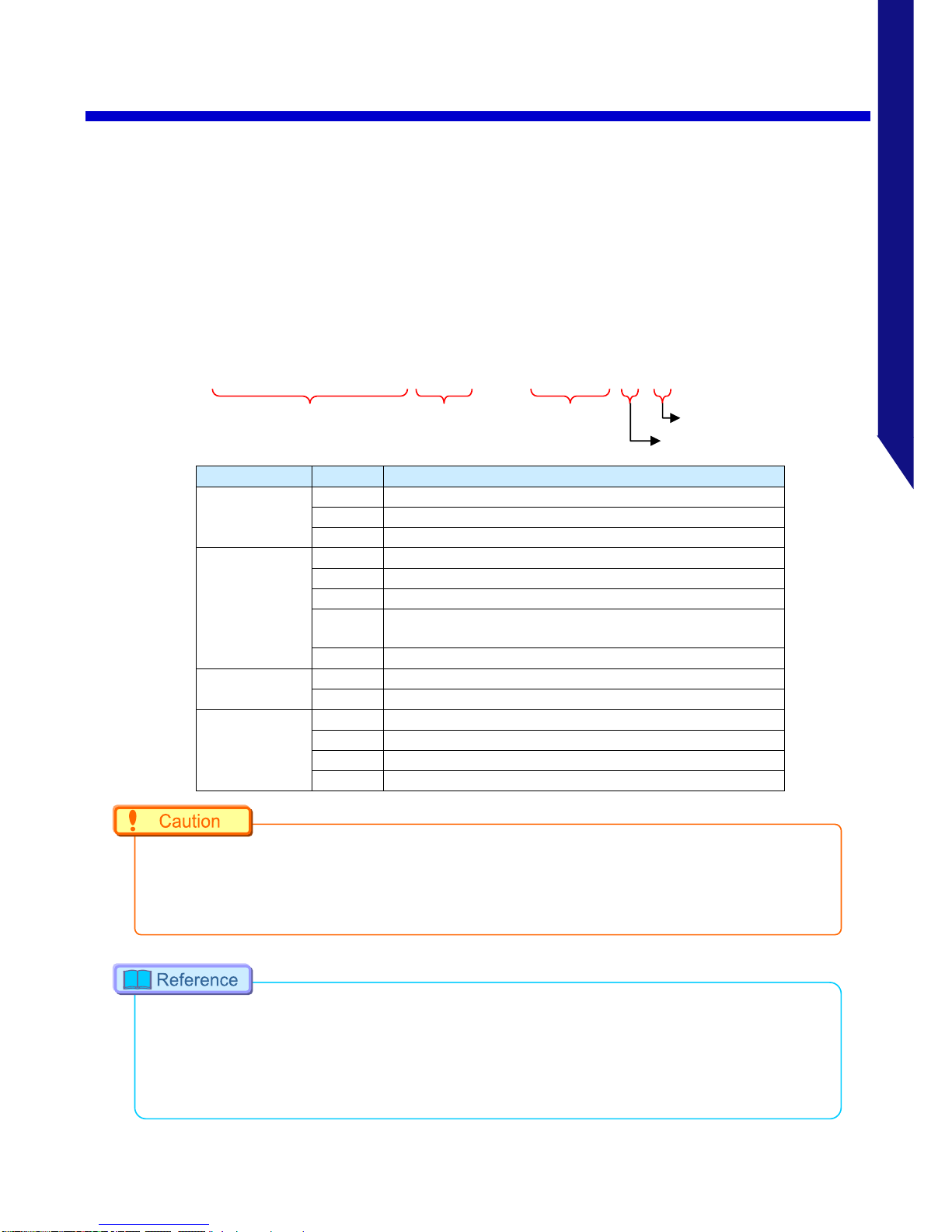
1.1.3. Type
For the system, there are monochrome and color versions, and for each of these versions,
there are 8 GB standard memory capacity type and 16 GB (or 16GB, 32GB, 64GB) high
capacity type.
When purchasing, it is possible to select from these models according to the application or
your demands.
The type categories are listed as follows.
◼ Camera type name and category
Item
list
Explanation
Full Frame
Frame Rate
S6
6,400fps
S9
9,000fps
S12
12,800fps
Fame Rate
1000K
1,000,000fps
900K
900,000fps
800K
800,000fps
500K
500,000fps (Supports fps up to 541,000 fps with
external synchronization)
200KS
200,000fps (Shutter speed 1usec control type)
Censor
M
monochrome
C
color
Memory
8GB
8 gigabyte
16GB
16 gigabyte
32GB
32 gigabyte
64GB
64 gigabyte
•
Export-controlled model type:type 200KS is subject to certain restriction on the frame
rate.
•
Export-controlled model type 200KSare subject to restriction on the shutter speed.
•
Subject to restrictions under Export Trade Control Order, your camera may NOT be used
depending on the country where you intend to use. If you are considering exporting your
camera, check with Photron first. Contact information is given in "Capter 5 Contacting
Photron5.1", 57 page.
FASTCAM Nova S12 type 1000K-C-64GB
Censor
Memory
Camera Name
Full Frame
Frame Rate
Fame
Rate

4
FASTCAM Nova
1.2 Part Names
1.2. Part Names
The system is composed of components including the camera body, AC power supply, and
the "Photron FASTCAM Viewer" control software (referred to below as PFV).
For the camera body and the AC power adapter
- Do not expose the camera body, AC power adapter and other optional components
to shock.
- Do not use in an area where flammable gas or dust is present.
- Do not place in an unstable location such as on an unstable platform or an incline.
- Do not disassemble or modify.
- Do not expose to liquids such as water.
- Do not subject to excessive force.
1.2.1. Camera Body
The camera body contains IC memory for image recording and has been designed to be
able to record high-speed images uncompressed. The back of the camera body is equipped
with the video output terminals, which can playback the recorded images on a video
monitor; the Gigabit Ethernet interface, which permits full camera control and data
download possible via connection to a PC; the input/output connector, which allows external
synchronization signals, trigger signals, IRIG time code.

5
FASTCAM Nova
1.2 Part Names
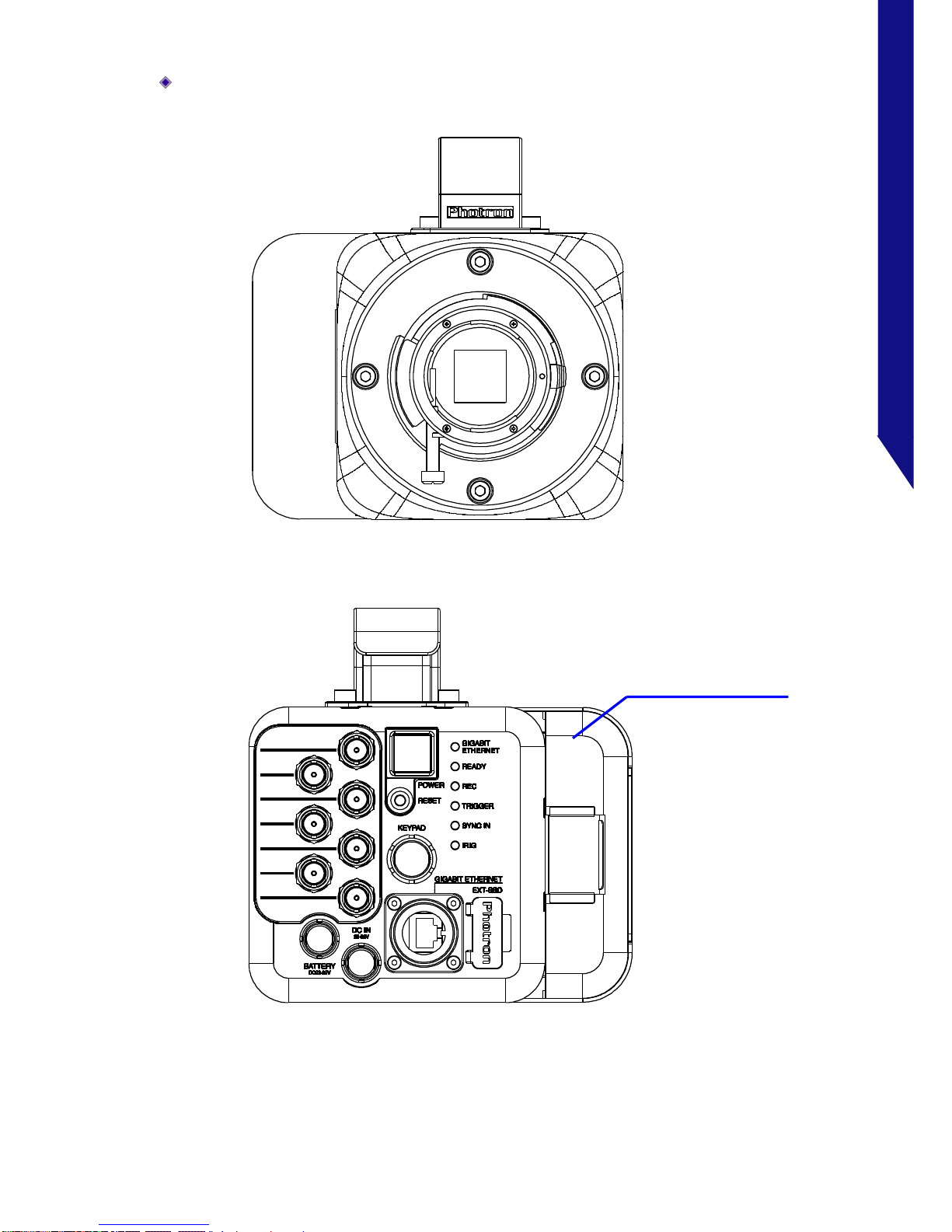
1.2.2. Camera Body Part Names
GtypeF Mount, without FAST Drive Holder
HD -SDI
TR IG S W I N
IR IG I N
IN PUT 1
IN PUT 2
OU TPUT 1
OU TPUT 2
DEF:S YNC IN
DEF:T RIG TTL IN
DEF:S YNC OUT
DEF:T RIG TTL OUT
GtypeF Mount
DC IN
22-32V
Primary Power Supply
Connector
Handle
POWER
Power Switch
I/O, HD-SDI Connector
BATTERY
DC22-32V
Secondary Power Supply
Connector
GIGABIT ETHERNET
Gigabit Ethernet
LAN Cable Connector
EXT-SSD
FAST Drive Connector
KEYPAD
Keypad Connector
(Reserved)
Status Indicator LED
RESET
Reset Switch
6
FASTCAM Nova
1.2 Part Names
GtypeF Mount, with FAST Drive Holder
HD -SDI
TR IG S W I N
IR IG I N
IN PUT 1
IN PUT 2
OU TPUT 1
OU TPUT 2
DEF:S YNC I N
DEF:T RIG T TL IN
DEF:S YNC O UT
DEF:T RIG T TL OUT
FAST Drive Holder

7
FASTCAM Nova
1.2 Part Names
1.2.3. Interchangeable Lens Mount
The lens mount on the system can be changed according to the recording purpose.
There are 3 types of interchangeable lens mounts: “G type F Mount”, “C Mount”, and “EF
Mount (Option)”.
The system has mechanical shutter as a standard feature.
How to change the lens mount (G type F Mount → C Mount)
1. Remove the four M5 bolts with the hexagonal holes using the hexagonal wrench.
2. Remove the G type F Mount portion as a unit.
3. Install the C Mount unit using the bolts with hexagonal holes in the 90° diagonal holes.
4. After installation, always verify that the unit is not loose and does not rattle.
GtypeF Mount
(Standard)
C Mount

8
FASTCAM Nova
1.2 Part Names
1.2.4. Status Display LEDs on the Rear of the Camera Body
There are a number of LEDs on the rear of the system's
camera body. These LEDs indicate the status of the system.
The function of each LED is explained here.
Item
Color
ON
FLASHING
OFF
POWER Power On
―
Power Off
GIGABIT
ETHERNET
The Gigabit Ethernet
interface is connected
Data is transferring
The Gigabit Ethernet
interface is not
connected
READY ―
Ready to record
Not ready to record
REC Recording
ENDLESS recording
Not recording
TRIGGER
A trigger signal is
present (being input)
(The LED will illuminate
for 0.1 second when the
trigger signal is input)
―
The trigger signal is not
present
SYNC IN
Synchronization signal is
not input in external
synchronization mode
Synchronization signal is
input in external
synchronization mode
Internal synchronization
mode
IRIG
IRIG signal is not input in
IRIG mode
IRIG signal is input in
IRIG mode
IRIG mode off
Illumination/blinking in operational states
◼ During low light mode operation
LEDs other than POWER (Green) and GIGABIT ETHERNET (Red) blink at a regular interval.
◼ When calibration is run from USER SW or the remote controller
LEDs other than POWER (Green) and GIGABIT ETHERNET (Red) blink at alternately from up to down
three times and from down to up three times.
◼ During the Gigabit Ethernet interface initialization
LEDs other than POWER (Green) and GIGABIT ETHERNET (Red) blink at alternately from right to left
three times and from left to right three times.

9
FASTCAM Nova
1.2 Part Names
1.2.5. Power Supply Connector, DC Cable
This is a DC power supply input connector. Connect to the supplied AC adapter.
The cable connector is optionally available. When using other power supplies, construct a
cable using the pin diagram below as a reference.
Power connector(Body side)
Pin Diagram
DC Cable (Body side)
Pin Diagram
DC Cable (Adapter side)
Pin Diagram
FGJ.1B.304.CYMD62Z
GMA.1B.054.DN
JJB1156
Connector
Name
Signal Name
Pin
No.
Connector Model Name
(Manufacturer)
Power
connector
(
Body side
)
+Vo
1
FGJ.1B.304.CYMD62Z (LEMO)
+Vo
2
GND
3
GND
4
DC cable
(
Connector
side
)
+Vo
1
GMA.1B.054.DN (LEMO)
+Vo
2
GND
3
GND
4
DC cable
(
Adapter side
)
+Vo
1
JJB1156 (LEMO)
+Vo
2
GND
3
GND
4

10
FASTCAM Nova
1.2 Part Names
When using the connector pins directly, refer to the chart above and ensure the
wiring is correct.
If the wiring is incorrect, not only is there the danger of the system
malfunctioning, but also of fire and electric shock.
Do not use a power supply which does not meet the system's specifications, or a
power supply you cannot guarantee the safety of.
By using a power supply outside of the system specifications, not only is there
the danger of the system malfunctioning, but also of fire and electric shock.
Please use an external power supply with the suitable rating which was estimated
by IEC/EN 61010-1 3rd Edition (compiled with CI. 6.3 and CI. 2.5), and separated
from the main circuit by double insulation or reinforced insulation.
Although this system is compatible with outdoor use, the AC power supply unit is
not outdoor compatible. When using it outdoors, prepare another power supply.
Warning
Warning
Warning
Warning

11
FASTCAM Nova
1.2 Part Names
1.2.6. Gigabit Ethernet Connector
It is an Ethernet connector for communicating with the PC and is a common RJ45
connector.
Connect a 1000BASE-T compatible interface board and this product with a LAN cable. For
the LAN cable, prepare a UTP or STP Cat 5e (enhanced category 5) or higher LAN cable.
(UTP: Unshielded Twisted Pair, STP: Shielded Twisted Pair)
The maximum cable length between the PC and the system is, compliant to the
1000BASE-T specification, up to 100 m. One PC can connect to a maximum of 64 Photron
Gigabit Ethernet interface equipped cameras using a hub. When connecting multiple
devices, connect through a switching hub that can connect at 1000BASE-T. The maximum
length of the cable that connects the system (or PC) to the switching hub is also 100 m.
•
Photron recommends using an STP cable over long distances or in noisy locations.
•
When connecting the camera to a network device of 10G Ethernet, it is necessary to set
the setting on the network device side to "1Gbps" speed or to add a switching HUB
corresponding to 1000 BASE-T in between.
•
The system's factory default IP address is below:
IP ADDRESS : 192.168.0.10
NETMASK : 255.255.255.0
GATEWAY ADDRESS : 0.0.0.0

12
FASTCAM Nova
1.2 Part Names
1.2.7. EXT-SSD Connector
It is installed as a standard in Nova.
Remove the EXT-SSD connector cover on the back of the camera and use it.
The EXT-SSD connector is for connecting the FAST Drive for saving data.
Use the optional FAST Drive exclusive cable to connect the FAST Drive.
•
For details on how to use it, please refer to “FAST Drive / FAST Dock User’s Manual”.

13
FASTCAM Nova
1.2 Part Names
1.2.8. RESET Switch
There is RESET switch that can be set on the back of the system.
◼ Camera IP Address Initialization
In some circumstance when the IP address is changed, and the new IP address is not explicit, an IP
Address Initialization operation is recommended. In this case, the IP address will be reset to 192.168.0.10
as the factory settings.
1. Press and hold the RESET switch at the camera’s back side.
2. All of the LEDs on the camera’s back side light, then they turn off from top to bottom. All of
LEDs blink twice after they turn off.
3. Reboot the camera. The IP address is reset to the factory setting.
•
If pressing and holding the RESET switch is stopped during LEDs are turning off from top
to bottom, the IP address reset is not accomplished. Press and hold the switch until they
blink certainly.
•
If pressing and holding the RESET switch is kept after the LEDs blink, “Factory Default” is
executed.
◼ Reset to the Factory Default
Camera settings can be reset to the factory default state by the following procedure.
1. Press and hold the RESET switch on the camera’s back side.
2. All of the LEDs on the camera’s back side light, then they turn off from top to bottom (first
time). All of LEDs blink twice after they turn off. (An IP address is reset.)
3. All of LEDs light, then they turn off from top to bottom (second time). All of LEDs blink twice
after they turn off. And they light again.
4. The LEDs turn off from top to bottom (third time). After that, they turn to keep blinking.
5. Reboot the camera. The camera settings are reset to the factory default.
•
To reset to the factory default, press and hold the RESET switch until all of LEDs blink after
3 times turning off from top to bottom.
•
If pressing and holding the RESET switch is stopped when the LEDs’ turning off from top to
bottom is finished 1 time, only an IP address is reset.

14
FASTCAM Nova
1.3 Input / Output Signal Types
1.3. Input / Output Signal Types
With the system, many signals can be input and output through the I/O connector. Signals
that can be input and output from the I/O connecter are listed below.
A signal other than the specified signal must not be input to the various connectors.
Use extreme caution as there is a risk of damage to both, the input device and the
output device.
1.3.1. TRIG SW IN
This trigger is input during the READY or ENDLESS recording state by contact between the
BNC connector’s shield and a center pin (switch closure). The center pin normally has
voltage flowing through it. Use caution to avoiding contact with other pins.
Connector Name
(Input System)
Menu
Signal
TRIG SW IN
None
Contact signal

15
FASTCAM Nova
1.3 Input / Output Signal Types
1.3.2. INPUT 1/2
The effect when a signal is input is described below, and can be optionally selected and
set.
The input voltage is 0V to +12V (H level +3.3V to +12V), positive or negative polarity,
pulse width is 200 ns or greater.
Default settings are INPUT1 connector is assigned “SYNC POS”, INPUT2 connector is
assigned “TRIG POS”.
Menu Display
Contents
Signal
(Input Signal Conditions)
TRIG POS
Inputs a positive polarity trigger signal.
FET Input 0V - +12V (H
level +3.3V to +12V),
Positive Polarity
TRIG NEG
Inputs a negative polarity trigger signal.
FET Input 0V - +12V (H
level +3.3V to +12V),
Negative Polarity
READY POS
Inputs a positive polarity READY signal.
By inputting in the live state, switch
READY ON / OFF.
In addition, by inputting while
recording, cancel the recording state.
FET Input 0V - +12V (H
level +3.3V to +12V),
Positive Polarity
READY NEG
Inputs a negative polarity READY
signal.
By inputting in the live state, switch
READY ON / OFF.
In addition, by inputting while
recording, cancel the recording state.
FET Input 0V - +12V (H
level +3.3V to +12V),
Negative Polarity
SYNC POS
Inputs the signal with positive polarity.
Input the synchronization signal from
the camera or external device.
FET Input 0V - +12V (H
level +3.3V to +12V),
Positive Polarity
SYNC NEG
Inputs the signal with negative polarity.
Input the synchronization signal from
the camera or external device.
FET Input 0V - +12V (H
level +3.3V to +12V),
Negative Polarity
EVENT POS
Input the signal with positive polarity.
By inputting during recording, "Event
marker" is displayed separately from
the trigger point in the data after
recording.
FET Input 0V - +12V (H
level +3.3V to +12V),
Positive Polarity
EVENT NEG
Input the signal with negative polarity.
By inputting during recording, "Event
marker" is displayed separately from
the trigger point in the data after
recording.
FET Input 0V - +12V (H
level +3.3V to +12V),
Negative Polarity

16
FASTCAM Nova
1.3 Input / Output Signal Types
1.3.3. IO INPUT Circuit Diagram

17
FASTCAM Nova
1.3 Input / Output Signal Types
1.3.4. OUTPUT 1/2
These are also BNC connectors. The signals below can be changed and output from PFV.
The output voltage is 0V to +5V, positive or negative polarity, pulse width can be changed.
Default settings are OUTPUT1 connector is ”SYNC POS”, OUTPUT2 is ”TRIG POS”.
Menu Display
Contents
Signal Type
SYNC POS
Outputs a positive polarity vertical
synchronization signal.
+5V CMOS output, Positive
Polarity
SYNC NEG
Outputs a negative polarity vertical
synchronization signal.
+5V CMOS output, Negative
Polarity
EXPOSE POS
Outputs the sensor's exposure
interval at H level.
+5V CMOS output, Positive
Polarity
EXPOSE NEG
Outputs the sensor's exposure
interval at L level.
+5V CMOS output, Negative
Polarity
REC POS
Outputs an interval signal during
recording at H level.
+5V CMOS output, Positive
Polarity
REC NEG
Outputs an interval signal during
recording at L level.
+5V CMOS output, Negative
Polarity
TRIG POS
Outputs the trigger signal received
by the camera at H level.
+5V CMOS output, Positive
Polarity
For TRIG SW IN
Normally Open, approx. 25usec
Normally Close, approx. 220usec
For TRIG TTL IN
POS:approx. 176 to 208nsec
NEG:approx. 248 to 280nsec
For GENERAL IN
POS:approx. 146 to 176nsec
NEG:approx. 232 to 264nsec
TRIG NEG
Outputs the trigger signal received
by the camera at L level.
+5V CMOS output, Negative
Polarity
For TRIG SW IN
Normally Open, approx. 25usec
Normally Close, approx. 220usec
For TRIG TTL IN
POS:approx. 176 to 208nsec
NEG:approx. 248 to 280nsec
For GENERAL IN
POS:approx. 146 to 176nsec
NEG:approx. 232 to 264nsec
READY POS
Outputs a signal at H level during the
trigger wait state.
(READY in START mode.) Only valid
during START, CENTER, END, and
MANUAL modes.
+5V CMOS output, Positive
Polarity
READY NEG
Outputs a signal at L level during the
trigger wait state.
(READY in START mode.) Only valid
during START, CENTER, END, and
MANUAL modes.
+5V CMOS output, Negative
Polarity
When using 50 cm cable from the signal generator to the camera

18
FASTCAM Nova
1.3 Input / Output Signal Types
1.3.5. Using External Synchronization Signals
An external synchronization mode to synchronize to an external signal is provided on the
system. By using an external synchronization signal, recording can be conducted using
multiple cameras to synchronize the timing of the shots or to also synchronize the shots
with external measuring devices and lighting. The procedure and precautions for using the
external synchronization signal are explained below.
◼ Inputting an External Synchronization Signal
An external synchronization signal can be input with the system. See the chart below for
external synchronization input settings.
メニュー表示
内容
OFF
Sets external synchronization off, operates independently.
ON CAM
The camera synchronizes with external signals below the currently set fps.
The fps set at the beginning is displayed on the display.
ON OTHER
The camera synchronizes with the signal input when changing the setting
to ON OTHER.
On the display, it becomes the fps at the time of setting change, and it
synchronizes with the signal below this frequency.
After synchronization setting, shutter speed and resolution can be
changed but fps can not be changed.
◼ Outputting an External Synchronization Signal
The system can externally output a synchronization signal. See the chart below for
external synchronization output settings.
Menu
Display
Contents
Signal Type
Delay Time
SYNC POS
Outputs a positive
polarity vertical
synchronization signal.
CMOS (74ACT541 buffer)
output, positive polarity
Approx. 168nsec
SYNC NEG
Outputs a negative
polarity vertical
synchronization signal.
CMOS (74ACT541 buffer)
output, negative polarity
Approx. 168nsec
•
When changing to the "ON OTHER" setting without inputting the synchronization signal,
the state will be "50Hz(E-Sync)".
After that, even if you input the synchronization signal, it will operate at 50 Hz so please
execute "ON OTHER" setting again after inputting the synchronization signal.

19
FASTCAM Nova
1.3 Input / Output Signal Types
1.3.6. Synchronization with a variable frequency
When synchronizing with a varying input frequency signal, the frame rate and resolution
specified before recording will be kept as a maximum value, and the camera frequency can
alternate to a minimum of about 60Hz following to the input signal, even under the
recording mode.
•
When an input sync signal is variable, or when it exceeds the upper limit frequency, the
output image quality might be worse.
•
If this phenomenon happens, the image quality can be recovered by reducing about 16 to
40 pixels of vertical resolution.

20
FASTCAM Nova
1.3 Input / Output Signal Types
1.3.7. Signal Delay
With the system, you can set the signal delay time or pulse width for the various signals that are
input and output. Pulse width and delay settings for the various signals to input/output are made with
PFV or the remote controller (optional). The content of each setting is listed in the chart below.
Setting Item
Setting Range (Value)
TRIG TTL IN DELAY
0-60 (s) 100 ns units
SYNC IN DELAY
0-1/frame rate (s) 100 ns units
GENERAL IN DELAY
0-60 (s) 100 ns units
TRIG OUT WIDTH
0-1 (ms) 100 ns units
SYNC OUT DELAY
0-1/frame rate (s) 100 ns units
SYNC OUT WIDTH
0-500 (us), 1/frame rate (s) at 2,000 fps or higher 100 ns units
EXPOSE OUT DELAY
0-1/frame rate (s) 100 ns units
SYNC OUT TIMES
0.5, 1, 2, 4, 6, 8, 10, 20, 30 (* x1 is standard output)
SYNC OUT TIMES
Values 1, 2, 4, 6, 8, 10. A value of 1 is normal output.
Set from the SYNC IN/OUT menu, SYNC OUT TIMES submenu.
Output a SYNC (vertical synchronization signal) from SYNC OUT that is 30 times SYNC.
Example: For a frame rate of 1,000 fps, SYNC OUT TIMES setting of 2.
Example: For a frame rate of 1,000 fps, SYNC OUT TIMES setting of 4.
SYNC OUT Output
1,000 fps Synchronization Signal
1,000 fps Synchronization Signal
SYNC OUT Output

21
FASTCAM Nova
1.3 Input / Output Signal Types
•
An accurate frequency is output, but when SYNC OUT TIMES is set to a large value with a high
frame rate, the setting may result in frequency errors.
•
There are following limitations in SYNC OUT TIMES function.
Frame Rate
Restriction
~
60,000fps
No Limit
60,001fps
~
90,000fps
x30 is unavailable
90,001fps
~
500,000fps
x20 and x30 are unavailable
500,001fps
~
1,000,000fps
x8, x10, x20 and x30 are unavailable
•
The following signal input cannot be accepted during the delay period。
•
Export-controlled model type is subject to certain restriction on the frame rate.

22
FASTCAM Nova
1.3 Input / Output Signal Types
1.3.8. IRIG IN (External Time Synchronization)
The system supports IRIG-B input and can add an IRIG code to each recorded frame. The
sample timing for the IRIG code is once each frame.
The recorded IRIG code is displayed on a “PFV”.
◼ IRIG Code Input Specification
Connector
BNC
Code Format
IRIG-B (122) Analog
Amplitude
1.0Vp-p min,8.0Vp-p max
Mark to space ratio
3:1 to 6:1
Typical modulated carrier signal ratio
10:1
•
IRIG Time Code is used when synchronizing a camera with external equipment in time.
•
It is a convenient function when apparatus is physically separated.
•
When the IRIG code is being input, the IRIG code is displayed in white, and is displayed to the left.
•
The IRIG offset time is also displayed below it. When the IRIG code is not being input, the IRIG
code is displayed in grey. At that time, the counter is the camera’s internal counter and it continues
to count.
•
Limitation of use of IRIG code
With the Image Trigger function, IRIG code cannot be used when the specified number of frames
is 32 or fewer in RANDOM CENTER or RANDOM MANUAL trigger mode.

23
FASTCAM Nova
1.3 Input / Output Signal Types
1.3.9. IRIG-sync Operation
This camera system supports IRIG-sync operation, in which the sensor drive signal is
synchronized with the input of IRIG-B signal.
◼ How IRIG-sync operation works?
In IRIG-sync operation, the image sensor is driven by the timing signal shown below.
Exposure to the sensor starts at the start of the IRIG-1PPS signal
IRIG-B :IRIG code that is input to the camera
IRIG-1PPS :1PPS timing of the IRIG code
EXPOSURE :Exposure to the camera sensor (exposure is indicated by high duration)
CAM_V :Camera’s vertical sync signal
IRIG-B
IRIG - 1PPS
EXPOSURE
CAM_V

24
FASTCAM Nova
1.4 Device Connections
1.4. Device Connections
1.4.1. Minimum Equipment Connection
The minimum connection for using the camera is as follows.
•
Refer to “Photron FASTCAM Viewer 4 User’s Manual” for software operation.
PC with PFV
installed
LAN cable
(Gigabit Ethernet)
AC Power cord
DC cable
AC power adapter

25
FASTCAM Nova
1.4 Device Connections
1.4.2. Connecting a Video Monitor
Connecting video monitors to the system for checking the live image (camera
pass-through image).
Connect a video input connector on a HD-SDI monitor to the “HD-SDI” connector with a
BNC cable.
Resolution
Frequency
1080p
30Hz
25Hz
•
Use 5C-FB specification cables for HD-SDI output
HD-SDI connector (BNC)
The HD-SDI (High Definition
Serial Digital Interface) output.
Video Monitor, etc., Video Device

26
FASTCAM Nova
1.5 How to open the FAST Drive holder
1.5. How to open the FAST Drive holder
This section explains how to open the FAST Drive holder.
①
Pull out the flap (black part) of the FAST Drive holder as shown in the following figure.
②
Open the outside.

27
FASTCAM Nova
1.6 Change attachment position of FAST Drive holder
1.6. Change attachment position of FAST Drive holder
When using the camera sideways, or when the FAST Drive holder or handle is in the way, it
can be removed and used.
This section explains how to attach the FAST Drive holder from the front side to the left side
to the bottom side, and the handle from the top side to the left side as viewed from the front.
①
Remove the screws (2 top and 2 bottom) that attach the FAST Drive holder.
②
Remove the FAST Drive holder.
③
Remove the screws (2 top) that attach the Carrying handle.
④
Remove the Carrying handle.
①
①
①
①
②
③
③
④

28
FASTCAM Nova
1.6 Change attachment position of FAST Drive holder
⑤
Tilt the camera 90 degrees to the right.
⑥
Mount the Carrying handle with the screw as shown in the following figure.
⑦
Mount the FAST Drive holder with the screw as shown in the following figure
•
The handle can be removed and used, but it will be hot while the main unit is running, so
install and operate the handle and do not touch the main unit.
•
When using in a high temperature environment of 40 degrees or more, attach a special
FAST Drive holder to the top panel, or do not store FAST Drive in a dedicated FAST Drive
holder.
•
Since the fan is on the right side as seen from the front of the main unit, the FAST Drive
holder can not be mounted on this side.

2
Capter 2 Recording
This chapter explains operations
related to recording.

30
FASTCAM Nova
2.1 Selecting Frame Rate/ Resolution
2.1. Selecting Frame Rate/ Resolution
Images can be recorded with the system from 2fps to 12,800fps using the full 1,024 x 1,024
pixels (1,048,576 pixels) resolution of the image sensor. For frame rates higher than 12,800
fps, the high-speed recordings are achieved by restricting the readout area of the image
sensor.
Restricting resolution enables higher speed recording. It also reduces data amount and then
it enables longer time shooting/recording.
•
For the detailed setting, refer to "3.1.5 Frame Rate and Resolution", page 37.

31
FASTCAM Nova
2.2 Selecting Shutter Speed
2.2. Selecting Shutter Speed
The shutter speed (Exposure time) is independent of the frame rate, and it is possible to
control the exposure time in the frame using the electric shutter. By making an exposure that
is of a shorter period than the frame rate, high-speed objects can be shot without blur.
When the frame rate is lower than 1,000 fps, the shutter speed can be changed from
1/1,000 (1msec), and when the frame rate is 1,000 fps or higher, it can be changed from one
step shorter shutter speed than '1/frame' second to maximum 1/4,800,000 second (0.2usec)
(it depends on the setting).
•
For more information of Shutter Speed, refer to “3.1.6. Shutter Speed List”, page 43.
•
For low speed FPS operation at less than 1,000fps, we use a special high-speed sensor of
12,800fps at 1,024 x 1,024 resolution so you can't set shutter speed longer than 1/1,000
second. However, you can operate at 2fps to 1,000fps.
•
For example, when working under 500fps, the available shutter speed varies from 1/1,000
to 1/4,032,000 second. When working under 2,000fps, a shutter speed varying from one
faster step than 1/2,000 second, 1/2,020 second, to 1/4,800,000 second can be obtained.
•
By activating "Low Frame Rate Function" from PFV, it is possible to apply a shutter of less
than 1/1,000 seconds. However, with exposure shorter than 1/1,000 seconds, the image
quality will degrade significantly. For 2 to 30 fps, only 1/frame seconds can be set.

3
Capter 3 Product Specifications
This chapter explains the system’s
specifications.

33
FASTCAM Nova
3.1 Specifications
3.1. Specifications
3.1.1. Product Specifications
Image Sensor
CMOS image sensor
Sensor Resolution
1,024
×
1,024 pixels
Pixel Size
20um square
Frame Rate
For full frame operation
S12 : 12,800fps
S9 : 9,000fps
S6 : 6,400fps
Accuracy of frame rate
50 ppm
Lens Mount
G type F mount, C mount, EF mount (optional)
Recording Color Depth
Monochrome
12bit / 8bit
Color
RGB, each 12bit / 8bit (Bayer color filter method)
Shutter Method
Electronic shutter (Global shutter)
Recording Method
IC memory
Recording Memory
Capacity
8GB、16GB、32GB
、
64GB
Trigger Method
START, CENTER, END, MANUAL, RANDOM,
RANDOM RESET, RANDOM MANUAL
Gain Control
Hardware LUT on camera
Controllable via software
Image Output
Customization
Customizable LUT, brightness is changeable
External Synchronization
Input Signal
+3.3 to +12Vp-p, negative polarity/positive polarity (switchable)
External Synchronization
Output Signal
5 Vp-p, negative polarity/positive polarity (switchable)
Trigger Input Signal
TTL (+3.3 to +12V), contact
Other Output Signals
Other timing signal outputs
External Control
Gigabit Ethernet IF(PC)
Video Output Signal
HD SDI (Compliant with SMPTE 292M)
1080p
・・・
30Hz, 25Hz
With digital zoom, scroll, fit functions
Digital Interface
Gigabit Ethernet(1000BASE-T)

34
FASTCAM Nova
3.1 Specifications
3.1.2. Random Reset Delay/ Dead Time
The random reset delay and dead time of this system change according to the specific fps
and resolution condition. Please refer to the following two tables.
Mode
Color
Condition
Random
Reset Delay
Dead Time
Nomal Mode
For the resolution in the table below, set fps
to the white cell value or less.
1.8 usec
2.0 usec
HS Mode1
For the resolution in the table below, set fps
above the white cell value, and set to
the blue cell value or less.
1.3 usec
1.5 usec
HS Mode2
For the resolution in the table below, set fps
above the blue cell value, and set to
the orange cell value or less.
0.9 usec
0.8 usec
V Res
H Res
128
112
96
80
64
48
32
16
1024
100,000
100,000
125,000
144,000
160,000
200,000
250,000
375,000
80,000
96,000
100,000
125,000
144,000
160,000
200,000
250,000
896
100,000
120,000
125,000
160,000
187,500
225,000
288,000
400,000
96,000
100,000
120,000
125,000
150,000
180,000
225,000
288,000
768
120,000
125,000
150,000
160,000
200,000
250,000
320,000
400,000
100,000
115,200
125,000
150,000
160,000
200,000
240,000
300,000
640
125,000
150,000
160,000
200,000
225,000
250,000
320,000
480,000
120,000
125,000
144,000
160,000
187,500
200,000
250,000
320,000
512
160,000
160,000
200,000
225,000
250,000
320,000
375,000
500,000
125,000
150,000
160,000
187,500
200,000
240,000
288,000
360,000
384
187,500
200,000
225,000
250,000
300,000
360,000
400,000
576,000
160,000
160,000
192,000
200,000
240,000
250,000
320,000
375,000
256
225,000
250,000
250,000
320,000
360,000
400,000
500,000
576,000
187,500
200,000
225,000
250,000
250,000
300,000
360,000
400,000
128
288,000
320,000
320,000
375,000
500,000
576,000
750,000
1,000,000
225,000
250,000
250,000
300,000
400,000
500,000
576,000
576,000
320,000
360,000
400,000
450,000
•
During random reset recording, please trigger from either PFV or external input. If trigger
is input from both, malfunction may occur.
•
The same condition applies to all models of S12, S9, S6.

35
FASTCAM Nova
3.1 Specifications
3.1.3. Other Supported Function
Supported Function
Variable Framerate / Resolution
Auto Exposure
Dual Slope Shutter
Resolution Lock
Fan Control
Lens Control (optional)
IRIG Input
IRIG Synchronization
Variable Synchronization
Signal Delay Setting
SYNC OUT Times *
Event Marker
Shutter lock
Mechanical Shutter
Record While Save
Exposure Display with Auto Exposure
IRIG Time Stamp's selection function at exposure start / end
*When using at the frame rate in the vicinity of the limit value when synchronizing the
external device, the SYNC OUT TIMES may be limited due to the error of the input frequency.
•
Refer to "Photron FASTCAM Viewer 4 User's Manual" for other functions.

36
FASTCAM Nova
3.1 Specifications
3.1.4. General Specifications
Environment Conditions
Storage Temperature
-20 -60degC (No Condensation)
-4 -140degF (No Condensation)
Storage Humidity
85% or less (No Condensation)
Operating Temperature
0 -45degC (No Condensation)
32 -113degF (No Condensation)
Operating Humidity
80% or less (No Condensation)
Pollution degree
Degree 2 according to IEC60664-1
Overvoltage category
Category II according to IEC60664-1
Maximum use altitude
2,000m or lower
External Dimensions
Camera Body
120.0 (H) x 120.0 (W) x 217.2 (D) mm
excluding protrusion
4.72" (H) x4.72" (W) x 8.55" (D)
AC Adapter
44.0 (H) x 85.0 (W) x 170.0 (D) mm
excluding protrusion
1.7” (H) x 3.3” (W) x 0.6
”
(D)
AC Power Supply
Supply Voltage
100V - 240V (type A cable: up to 125V)
Supply Frequency
50Hz - 60Hz
Power Consumption
138W
DC Power Supply
Power Voltage
22V - 32V
Power Consumption
120VA
Weight
Camera Body
3.3kg 7.2 lbs
AC Adapter
0.8kg 1.7 lbs
Photron has verified two types of AC cables, type A (standard for Japan, USA, Canada,
etc.) and type SE (standard for Germany, France, etc.). However, when those cables
cannot properly receive power when plugged in, use the proper AC cable for the
region's standards and verify that AC cable works properly.
For inquiries regarding the recommended AC cable for each region, contact that
region's Photron branch office or the distributor.

37
FASTCAM Nova
3.1 Specifications
3.1.5. Frame Rate and Resolution
type S12 (1,024 x 1,024 - 512 x 480)
mage
Size
Frame
rate(fps)
1,024
x
1,024
1,024
x
944
1,024
x
880
1,024
x
768
1,024
x
688
1,024
x
512
896
x
896
896
x
864
768
x
768
768
x
672
768
x
560
640
x
640
640
x
480
512
x
512
512
x
480
2 ✔ ✔ ✔ ✔ ✔ ✔ ✔ ✔ ✔ ✔ ✔ ✔ ✔ ✔ ✔
5 ✔ ✔ ✔ ✔ ✔ ✔ ✔ ✔ ✔ ✔ ✔ ✔ ✔ ✔ ✔
10 ✔ ✔ ✔ ✔ ✔ ✔ ✔ ✔ ✔ ✔ ✔ ✔ ✔ ✔ ✔
30 ✔ ✔ ✔ ✔ ✔ ✔ ✔ ✔ ✔ ✔ ✔ ✔ ✔ ✔ ✔
50 ✔ ✔ ✔ ✔ ✔ ✔ ✔ ✔ ✔ ✔ ✔ ✔ ✔ ✔ ✔
60 ✔ ✔ ✔ ✔ ✔ ✔ ✔ ✔ ✔ ✔ ✔ ✔ ✔ ✔ ✔
125 ✔ ✔ ✔ ✔ ✔ ✔ ✔ ✔ ✔ ✔ ✔ ✔ ✔ ✔ ✔
250 ✔ ✔ ✔ ✔ ✔ ✔ ✔ ✔ ✔ ✔ ✔ ✔ ✔ ✔ ✔
500 ✔ ✔ ✔ ✔ ✔ ✔ ✔ ✔ ✔ ✔ ✔ ✔ ✔ ✔ ✔
750 ✔ ✔ ✔ ✔ ✔ ✔ ✔ ✔ ✔ ✔ ✔ ✔ ✔ ✔ ✔
1,000 ✔ ✔ ✔ ✔ ✔ ✔ ✔ ✔ ✔ ✔ ✔ ✔ ✔ ✔ ✔
2,000 ✔ ✔ ✔ ✔ ✔ ✔ ✔ ✔ ✔ ✔ ✔ ✔ ✔ ✔ ✔
3,000 ✔ ✔ ✔ ✔ ✔ ✔ ✔ ✔ ✔ ✔ ✔ ✔ ✔ ✔ ✔
4,000 ✔ ✔ ✔ ✔ ✔ ✔ ✔ ✔ ✔ ✔ ✔ ✔ ✔ ✔ ✔
5,000 ✔ ✔ ✔ ✔ ✔ ✔ ✔ ✔ ✔ ✔ ✔ ✔ ✔ ✔ ✔
6,000 ✔ ✔ ✔ ✔ ✔ ✔ ✔ ✔ ✔ ✔ ✔ ✔ ✔ ✔ ✔
7,200 ✔ ✔ ✔ ✔ ✔ ✔ ✔ ✔ ✔ ✔ ✔ ✔ ✔ ✔ ✔
8,000 ✔ ✔ ✔ ✔ ✔ ✔ ✔ ✔ ✔ ✔ ✔ ✔ ✔ ✔ ✔
9,000 ✔ ✔ ✔ ✔ ✔ ✔ ✔ ✔ ✔ ✔ ✔ ✔ ✔ ✔ ✔
10,000 ✔ ✔ ✔ ✔ ✔ ✔ ✔ ✔ ✔ ✔ ✔ ✔ ✔ ✔ ✔
12,800 ✔ ✔ ✔ ✔ ✔ ✔ ✔ ✔ ✔ ✔ ✔ ✔ ✔ ✔ ✔
15,000
✔ ✔ ✔ ✔ ✔ ✔ ✔ ✔ ✔ ✔ ✔ ✔ ✔ ✔
16,000
✔ ✔ ✔ ✔ ✔ ✔ ✔ ✔ ✔ ✔ ✔ ✔ ✔
18,000
✔ ✔ ✔
✔ ✔ ✔ ✔ ✔ ✔ ✔ ✔
20,000
✔ ✔ ✔ ✔ ✔ ✔ ✔ ✔ ✔
22,500
✔ ✔ ✔ ✔ ✔ ✔ ✔ ✔
25,000
✔
✔ ✔ ✔ ✔ ✔ ✔
30,000
✔ ✔ ✔ ✔ ✔
38,400
✔ ✔ ✔
40,000
✔ ✔ ✔
45,000
✔
50,000
64,000
75,000
80,000
90,000
100,000
115,200
125,000
160,000
180,000
200,000
225,000
250,000
288,000
320,000
400,000
500,000
576,000
720,000
750,000
900,000
1,000,000
The ✔ mark indicates a possible setting. Light blue items are the maximum resolution setting at that frame rate.
This table shows default settings. Even finer settings are possible with the variable setting feature.

38
FASTCAM Nova
3.1 Specifications
type S12 (512 x 384 - 128 x 16)
mage
Size
Frame
rate(fps)
512
x
384
512
x
336
512
x
256
384
x
384
384
x
256
384
x
240
256
x
256
256
x
160
256
x
128
128
x
128
128
x
96
128
x
64
128
x
48
128
x
32
128
x
16
2 ✔ ✔ ✔ ✔ ✔ ✔ ✔ ✔ ✔ ✔ ✔ ✔ ✔ ✔ ✔
5 ✔ ✔ ✔ ✔ ✔ ✔ ✔ ✔ ✔ ✔ ✔ ✔ ✔ ✔ ✔
10 ✔ ✔ ✔ ✔ ✔ ✔ ✔ ✔ ✔ ✔ ✔ ✔ ✔ ✔ ✔
30 ✔ ✔ ✔ ✔ ✔ ✔ ✔ ✔ ✔ ✔ ✔ ✔ ✔ ✔ ✔
50 ✔ ✔ ✔ ✔ ✔ ✔ ✔ ✔ ✔ ✔ ✔ ✔ ✔ ✔ ✔
60 ✔ ✔ ✔ ✔ ✔ ✔ ✔ ✔ ✔ ✔ ✔ ✔ ✔ ✔ ✔
125 ✔ ✔ ✔ ✔ ✔ ✔ ✔ ✔ ✔ ✔ ✔ ✔ ✔ ✔ ✔
250 ✔ ✔ ✔ ✔ ✔ ✔ ✔ ✔ ✔ ✔ ✔ ✔ ✔ ✔ ✔
500 ✔ ✔ ✔ ✔ ✔ ✔ ✔ ✔ ✔ ✔ ✔ ✔ ✔ ✔ ✔
750 ✔ ✔ ✔ ✔ ✔ ✔ ✔ ✔ ✔ ✔ ✔ ✔ ✔ ✔ ✔
1,000 ✔ ✔ ✔ ✔ ✔ ✔ ✔ ✔ ✔ ✔ ✔ ✔ ✔ ✔ ✔
2,000 ✔ ✔ ✔ ✔ ✔ ✔ ✔ ✔ ✔ ✔ ✔ ✔ ✔ ✔ ✔
3,000 ✔ ✔ ✔ ✔ ✔ ✔ ✔ ✔ ✔ ✔ ✔ ✔ ✔ ✔ ✔
4,000 ✔ ✔ ✔ ✔ ✔ ✔ ✔ ✔ ✔ ✔ ✔ ✔ ✔ ✔ ✔
5,000 ✔ ✔ ✔ ✔ ✔ ✔ ✔ ✔ ✔ ✔ ✔ ✔ ✔ ✔ ✔
6,000 ✔ ✔ ✔ ✔ ✔ ✔ ✔ ✔ ✔ ✔ ✔ ✔ ✔ ✔ ✔
7,200 ✔ ✔ ✔ ✔ ✔ ✔ ✔ ✔ ✔ ✔ ✔ ✔ ✔ ✔ ✔
8,000 ✔ ✔ ✔ ✔ ✔ ✔ ✔ ✔ ✔ ✔ ✔ ✔ ✔ ✔ ✔
9,000 ✔ ✔ ✔ ✔ ✔ ✔ ✔ ✔ ✔ ✔ ✔ ✔ ✔ ✔ ✔
10,000 ✔ ✔ ✔ ✔ ✔ ✔ ✔ ✔ ✔ ✔ ✔ ✔ ✔ ✔ ✔
12,800 ✔ ✔ ✔ ✔ ✔ ✔ ✔ ✔ ✔ ✔ ✔ ✔ ✔ ✔ ✔
15,000 ✔ ✔ ✔ ✔ ✔ ✔ ✔ ✔ ✔ ✔ ✔ ✔ ✔ ✔ ✔
16,000 ✔ ✔ ✔ ✔ ✔ ✔ ✔ ✔ ✔ ✔ ✔ ✔ ✔ ✔ ✔
18,000 ✔ ✔ ✔ ✔ ✔ ✔ ✔ ✔ ✔ ✔ ✔ ✔ ✔ ✔ ✔
20,000 ✔ ✔ ✔ ✔ ✔ ✔ ✔ ✔ ✔ ✔ ✔ ✔ ✔ ✔ ✔
22,500 ✔ ✔ ✔ ✔ ✔ ✔ ✔ ✔ ✔ ✔ ✔ ✔ ✔ ✔ ✔
25,000 ✔ ✔ ✔ ✔ ✔ ✔ ✔ ✔ ✔ ✔ ✔ ✔ ✔ ✔ ✔
30,000 ✔ ✔ ✔ ✔ ✔ ✔ ✔ ✔ ✔ ✔ ✔ ✔ ✔ ✔ ✔
38,400 ✔ ✔ ✔ ✔ ✔ ✔ ✔ ✔ ✔ ✔ ✔ ✔ ✔ ✔ ✔
40,000 ✔ ✔ ✔ ✔ ✔ ✔ ✔ ✔ ✔ ✔ ✔ ✔ ✔ ✔ ✔
45,000 ✔ ✔ ✔ ✔ ✔ ✔ ✔ ✔ ✔ ✔ ✔ ✔ ✔ ✔ ✔
50,000 ✔ ✔ ✔ ✔ ✔ ✔ ✔ ✔ ✔ ✔ ✔ ✔ ✔ ✔ ✔
64,000
✔ ✔ ✔ ✔ ✔ ✔ ✔ ✔ ✔ ✔ ✔ ✔ ✔ ✔
75,000
✔
✔ ✔ ✔ ✔ ✔ ✔ ✔ ✔ ✔ ✔ ✔
80,000
✔
✔ ✔ ✔ ✔ ✔ ✔ ✔ ✔ ✔ ✔ ✔
90,000
✔ ✔ ✔ ✔ ✔ ✔ ✔ ✔ ✔ ✔ ✔
100,000
✔ ✔ ✔ ✔ ✔ ✔ ✔ ✔ ✔ ✔
115,200
✔ ✔ ✔ ✔ ✔ ✔ ✔ ✔ ✔
125,000
✔ ✔ ✔ ✔ ✔ ✔ ✔ ✔
160,000
✔ ✔ ✔ ✔ ✔ ✔ ✔ ✔
180,000
✔ ✔ ✔ ✔ ✔ ✔ ✔
200,000
✔ ✔ ✔ ✔ ✔ ✔ ✔
225,000
✔ ✔ ✔ ✔ ✔ ✔ ✔
250,000
✔ ✔ ✔ ✔ ✔ ✔
288,000
✔ ✔ ✔ ✔ ✔ ✔
320,000
✔○ ✔ ✔ ✔ ✔
400,000
✔ ✔ ✔ ✔
500,000
✔ ✔ ✔ ✔
576,000
✔ ✔ ✔
720,000
✔ ✔
750,000
✔ ✔
900,000
✔
1,000,000
✔
The ✔ mark indicates a possible setting. Light blue items are the maximum resolution setting at that frame rate.
This table shows default settings. Even finer settings are possible with the variable setting feature.

39
FASTCAM Nova
3.1 Specifications
type S9 (1,024 x 1,024 - 512 x 480)
mage
Size
Frame
rate(fps)
1,024
×
1,024
1,024
×
992
1,024
×
896
1,024
×
768
1,024
×
640
1,024
×
576
1,024
×
512
896
×
896
896
×
512
768
×
768
768
×
512
640
×
640
640
×
480
512
×
512
512
×
480
2 ✔ ✔ ✔ ✔ ✔ ✔ ✔ ✔ ✔ ✔ ✔ ✔ ✔ ✔ ✔
5 ✔ ✔ ✔ ✔ ✔ ✔ ✔ ✔ ✔ ✔ ✔ ✔ ✔ ✔ ✔
10 ✔ ✔ ✔ ✔ ✔ ✔ ✔ ✔ ✔ ✔ ✔ ✔ ✔ ✔ ✔
30 ✔ ✔ ✔ ✔ ✔ ✔ ✔ ✔ ✔ ✔ ✔ ✔ ✔ ✔ ✔
50 ✔ ✔ ✔ ✔ ✔ ✔ ✔ ✔ ✔ ✔ ✔ ✔ ✔ ✔ ✔
60 ✔ ✔ ✔ ✔ ✔ ✔ ✔ ✔ ✔ ✔ ✔ ✔ ✔ ✔ ✔
125 ✔ ✔ ✔ ✔ ✔ ✔ ✔ ✔ ✔ ✔ ✔ ✔ ✔ ✔ ✔
250 ✔ ✔ ✔ ✔ ✔ ✔ ✔ ✔ ✔ ✔ ✔ ✔ ✔ ✔ ✔
500 ✔ ✔ ✔ ✔ ✔ ✔ ✔ ✔ ✔ ✔ ✔ ✔ ✔ ✔ ✔
750 ✔ ✔ ✔ ✔ ✔ ✔ ✔ ✔ ✔ ✔ ✔ ✔ ✔ ✔ ✔
1,000 ✔ ✔ ✔ ✔ ✔ ✔ ✔ ✔ ✔ ✔ ✔ ✔ ✔ ✔ ✔
2,000 ✔ ✔ ✔ ✔ ✔ ✔ ✔ ✔ ✔ ✔ ✔ ✔ ✔ ✔ ✔
3,000 ✔ ✔ ✔ ✔ ✔ ✔ ✔ ✔ ✔ ✔ ✔ ✔ ✔ ✔ ✔
4,000 ✔ ✔ ✔ ✔ ✔ ✔ ✔ ✔ ✔ ✔ ✔ ✔ ✔ ✔ ✔
5,000 ✔ ✔ ✔ ✔ ✔ ✔ ✔ ✔ ✔ ✔ ✔ ✔ ✔ ✔ ✔
6,000 ✔ ✔ ✔ ✔ ✔ ✔ ✔ ✔ ✔ ✔ ✔ ✔ ✔ ✔ ✔
7,200 ✔ ✔ ✔ ✔ ✔ ✔ ✔ ✔ ✔ ✔ ✔ ✔ ✔ ✔ ✔
8,000 ✔ ✔ ✔ ✔ ✔ ✔ ✔ ✔ ✔ ✔ ✔ ✔ ✔ ✔ ✔
9,000 ✔ ✔ ✔ ✔ ✔ ✔ ✔ ✔ ✔ ✔ ✔ ✔ ✔ ✔ ✔
9,600
✔ ✔ ✔ ✔ ✔ ✔ ✔ ✔ ✔ ✔ ✔ ✔ ✔ ✔
10,000
✔ ✔ ✔ ✔ ✔ ✔ ✔ ✔ ✔ ✔ ✔ ✔ ✔
12,000
✔ ✔ ✔ ✔
✔ ✔ ✔ ✔ ✔ ✔ ✔
14,400
✔ ✔ ✔
✔ ✔ ✔ ✔ ✔ ✔ ✔
15,000
✔ ✔
✔ ✔ ✔ ✔ ✔ ✔ ✔
16,000
✔ ✔
✔
✔ ✔ ✔ ✔ ✔
18,000
✔
✔
✔ ✔ ✔ ✔ ✔
20,000
✔
✔ ✔ ✔ ✔ ✔
22,500
✔
✔ ✔ ✔
25,000
✔ ✔ ✔
28,800
✔ ✔
30,000
✔ ✔
32,000
✔
38,400
40,000
45,000
50,000
64,000
75,000
80,000
90,000
100,000
120,000
160,000
180,000
200,000
250,000
320,000
400,000
480,000
576,000
750,000
900,000
The ✔ mark indicates a possible setting. Light blue items are the maximum resolution setting at that frame rate.
This table shows default settings. Even finer settings are possible with the variable setting feature.

40
FASTCAM Nova
3.1 Specifications
type S9 (512 x 384 - 128 x 16)
mage
Size
Frame
rate(fps)
512
x
384
512
x
336
384
x
384
384
x
336
384
x
256
256
x
256
256
x
160
256
x
128
128
x
128
128
x
96
128
x
64
128
x
48
128
x
32
128
x
16
2 ✔ ✔ ✔ ✔ ✔ ✔ ✔ ✔ ✔ ✔ ✔ ✔ ✔ ✔
5 ✔ ✔ ✔ ✔ ✔ ✔ ✔ ✔ ✔ ✔ ✔ ✔ ✔ ✔
10 ✔ ✔ ✔ ✔ ✔ ✔ ✔ ✔ ✔ ✔ ✔ ✔ ✔ ✔
30 ✔ ✔ ✔ ✔ ✔ ✔ ✔ ✔ ✔ ✔ ✔ ✔ ✔ ✔
50 ✔ ✔ ✔ ✔ ✔ ✔ ✔ ✔ ✔ ✔ ✔ ✔ ✔ ✔
60 ✔ ✔ ✔ ✔ ✔ ✔ ✔ ✔ ✔ ✔ ✔ ✔ ✔ ✔
125 ✔ ✔ ✔ ✔ ✔ ✔ ✔ ✔ ✔ ✔ ✔ ✔ ✔ ✔
250 ✔ ✔ ✔ ✔ ✔ ✔ ✔ ✔ ✔ ✔ ✔ ✔ ✔ ✔
500 ✔ ✔ ✔ ✔ ✔ ✔ ✔ ✔ ✔ ✔ ✔ ✔ ✔ ✔
750 ✔ ✔ ✔ ✔ ✔ ✔ ✔ ✔ ✔ ✔ ✔ ✔ ✔ ✔
1,000 ✔ ✔ ✔ ✔ ✔ ✔ ✔ ✔ ✔ ✔ ✔ ✔ ✔ ✔
2,000 ✔ ✔ ✔ ✔ ✔ ✔ ✔ ✔ ✔ ✔ ✔ ✔ ✔ ✔
3,000 ✔ ✔ ✔ ✔ ✔ ✔ ✔ ✔ ✔ ✔ ✔ ✔ ✔ ✔
4,000 ✔ ✔ ✔ ✔ ✔ ✔ ✔ ✔ ✔ ✔ ✔ ✔ ✔ ✔
5,000 ✔ ✔ ✔ ✔ ✔ ✔ ✔ ✔ ✔ ✔ ✔ ✔ ✔ ✔
6,000 ✔ ✔ ✔ ✔ ✔ ✔ ✔ ✔ ✔ ✔ ✔ ✔ ✔ ✔
7,200 ✔ ✔ ✔ ✔ ✔ ✔ ✔ ✔ ✔ ✔ ✔ ✔ ✔ ✔
8,000 ✔ ✔ ✔ ✔ ✔ ✔ ✔ ✔ ✔ ✔ ✔ ✔ ✔ ✔
9,000 ✔ ✔ ✔ ✔ ✔ ✔ ✔ ✔ ✔ ✔ ✔ ✔ ✔ ✔
9,600 ✔ ✔ ✔ ✔ ✔ ✔ ✔ ✔ ✔ ✔ ✔ ✔ ✔ ✔
10,000 ✔ ✔ ✔ ✔ ✔ ✔ ✔ ✔ ✔ ✔ ✔ ✔ ✔ ✔
12,000 ✔ ✔ ✔ ✔ ✔ ✔ ✔ ✔ ✔ ✔ ✔ ✔ ✔ ✔
14,400 ✔ ✔ ✔ ✔ ✔ ✔ ✔ ✔ ✔ ✔ ✔ ✔ ✔ ✔
15,000 ✔ ✔ ✔ ✔ ✔ ✔ ✔ ✔ ✔ ✔ ✔ ✔ ✔ ✔
16,000 ✔ ✔ ✔ ✔ ✔ ✔ ✔ ✔ ✔ ✔ ✔ ✔ ✔ ✔
18,000 ✔ ✔ ✔ ✔ ✔ ✔ ✔ ✔ ✔ ✔ ✔ ✔ ✔ ✔
20,000 ✔ ✔ ✔ ✔ ✔ ✔ ✔ ✔ ✔ ✔ ✔ ✔ ✔ ✔
22,500 ✔ ✔ ✔ ✔ ✔ ✔ ✔ ✔ ✔ ✔ ✔ ✔ ✔ ✔
25,000 ✔ ✔ ✔ ✔ ✔ ✔ ✔ ✔ ✔ ✔ ✔ ✔ ✔ ✔
28,800 ✔ ✔ ✔ ✔ ✔ ✔ ✔ ✔ ✔ ✔ ✔ ✔ ✔ ✔
30,000 ✔ ✔ ✔ ✔ ✔ ✔ ✔ ✔ ✔ ✔ ✔ ✔ ✔ ✔
32,000 ✔ ✔ ✔ ✔ ✔ ✔ ✔ ✔ ✔ ✔ ✔ ✔ ✔ ✔
38,400 ✔ ✔ ✔ ✔ ✔ ✔ ✔ ✔ ✔ ✔ ✔ ✔ ✔ ✔
40,000
✔ ✔ ✔ ✔ ✔ ✔ ✔ ✔ ✔ ✔ ✔ ✔ ✔
45,000
✔ ✔ ✔ ✔ ✔ ✔ ✔ ✔ ✔ ✔ ✔ ✔
50,000
✔ ✔ ✔ ✔ ✔ ✔ ✔ ✔ ✔ ✔ ✔
64,000
✔ ✔ ✔ ✔ ✔ ✔ ✔ ✔ ✔ ✔
75,000
✔ ✔ ✔ ✔ ✔ ✔ ✔ ✔ ✔
80,000
✔ ✔ ✔ ✔ ✔ ✔ ✔ ✔ ✔
90,000
✔ ✔ ✔ ✔ ✔ ✔ ✔ ✔
100,000
✔ ✔ ✔ ✔ ✔ ✔ ✔ ✔
120,000
✔ ✔ ✔ ✔ ✔ ✔ ✔ ✔
160,000
✔ ✔ ✔ ✔ ✔ ✔ ✔
180,000
✔ ✔ ✔ ✔ ✔ ✔
200,000
✔ ✔ ✔ ✔ ✔ ✔
250,000
✔ ✔ ✔ ✔ ✔
320,000
✔ ✔ ✔ ✔
400,000
✔ ✔ ✔ ✔
480,000
✔ ✔ ✔
576,000
✔ ✔
750,000
✔
900,000
✔
The ✔ mark indicates a possible setting. Light blue items are the maximum resolution setting at that frame rate.
This table shows default settings. Even finer settings are possible with the variable setting feature.

41
FASTCAM Nova
3.1 Specifications
type S6 (1,024 x 1,024 - 512 x 480)
mage
Size
Frame
rate(fps)
1,024
x
1,024
1,024
x
992
1,024
x
896
1,024
x
768
1,024
x
672
1,024
x
576
1,024
x
512
896
x
896
896
x
512
768
x
768
768
x
512
640
x
640
640
x
480
512
x
512
512
x
480
2 ✔ ✔ ✔ ✔ ✔ ✔ ✔ ✔ ✔ ✔ ✔ ✔ ✔ ✔ ✔
5 ✔ ✔ ✔ ✔ ✔ ✔ ✔ ✔ ✔ ✔ ✔ ✔ ✔ ✔ ✔
10 ✔ ✔ ✔ ✔ ✔ ✔ ✔ ✔ ✔ ✔ ✔ ✔ ✔ ✔ ✔
30 ✔ ✔ ✔ ✔ ✔ ✔ ✔ ✔ ✔ ✔ ✔ ✔ ✔ ✔ ✔
50 ✔ ✔ ✔ ✔ ✔ ✔ ✔ ✔ ✔ ✔ ✔ ✔ ✔ ✔ ✔
60 ✔ ✔ ✔ ✔ ✔ ✔ ✔ ✔ ✔ ✔ ✔ ✔ ✔ ✔ ✔
125 ✔ ✔ ✔ ✔ ✔ ✔ ✔ ✔ ✔ ✔ ✔ ✔ ✔ ✔ ✔
250 ✔ ✔ ✔ ✔ ✔ ✔ ✔ ✔ ✔ ✔ ✔ ✔ ✔ ✔ ✔
500 ✔ ✔ ✔ ✔ ✔ ✔ ✔ ✔ ✔ ✔ ✔ ✔ ✔ ✔ ✔
750 ✔ ✔ ✔ ✔ ✔ ✔ ✔ ✔ ✔ ✔ ✔ ✔ ✔ ✔ ✔
1,000 ✔ ✔ ✔ ✔ ✔ ✔ ✔ ✔ ✔ ✔ ✔ ✔ ✔ ✔ ✔
2,000 ✔ ✔ ✔ ✔ ✔ ✔ ✔ ✔ ✔ ✔ ✔ ✔ ✔ ✔ ✔
3,000 ✔ ✔ ✔ ✔ ✔ ✔ ✔ ✔ ✔ ✔ ✔ ✔ ✔ ✔ ✔
4,000 ✔ ✔ ✔ ✔ ✔ ✔ ✔ ✔ ✔ ✔ ✔ ✔ ✔ ✔ ✔
5,000 ✔ ✔ ✔ ✔ ✔ ✔ ✔ ✔ ✔ ✔ ✔ ✔ ✔ ✔ ✔
6,000 ✔ ✔ ✔ ✔ ✔ ✔ ✔ ✔ ✔ ✔ ✔ ✔ ✔ ✔ ✔
6,400 ✔ ✔ ✔ ✔ ✔ ✔ ✔ ✔ ✔ ✔ ✔ ✔ ✔ ✔ ✔
7,200
✔ ✔ ✔ ✔ ✔ ✔ ✔ ✔ ✔ ✔ ✔ ✔ ✔ ✔
8,000 ✔ ✔ ✔ ✔ ✔ ✔ ✔ ✔ ✔ ✔ ✔ ✔ ✔
9,000
✔ ✔ ✔ ✔
✔ ✔ ✔ ✔ ✔ ✔ ✔
10,000
✔ ✔ ✔
✔ ✔ ✔ ✔ ✔ ✔ ✔
12,000
✔ ✔
✔
✔ ✔ ✔ ✔ ✔
12,800
✔
✔
✔ ✔ ✔ ✔ ✔
15,000
✔
✔ ✔ ✔ ✔ ✔
16,000
✔ ✔ ✔ ✔ ✔
18,000
✔ ✔ ✔
20,000
✔ ✔ ✔
22,500
✔ ✔
24,000
✔
28,800
30,000
32,000
36,000
40,000
50,000
64,000
75,000
80,000
90,000
100,000
125,000
160,000
180,000
200,000
250,000
300,000
320,000
400,000
500,000
576,000
800,000
The ✔ mark indicates a possible setting. Light blue items are the maximum resolution setting at that frame rate.
This table shows default settings. Even finer settings are possible with the variable setting feature.

42
FASTCAM Nova
3.1 Specifications
type S6 (512 x 384 - 128 x 16)
mage
Size
Frame
rate(fps)
512
x
384
512
x
336
384
x
384
384
x
336
384
x
256
256
x
256
256
x
160
256
x
128
128
x
128
128
x
96
128
x
64
128
x
48
128
x
32
128
x
16
2 ✔ ✔ ✔ ✔ ✔ ✔ ✔ ✔ ✔ ✔ ✔ ✔ ✔ ✔
5 ✔ ✔ ✔ ✔ ✔ ✔ ✔ ✔ ✔ ✔ ✔ ✔ ✔ ✔
10 ✔ ✔ ✔ ✔ ✔ ✔ ✔ ✔ ✔ ✔ ✔ ✔ ✔ ✔
30 ✔ ✔ ✔ ✔ ✔ ✔ ✔ ✔ ✔ ✔ ✔ ✔ ✔ ✔
50 ✔ ✔ ✔ ✔ ✔ ✔ ✔ ✔ ✔ ✔ ✔ ✔ ✔ ✔
60 ✔ ✔ ✔ ✔ ✔ ✔ ✔ ✔ ✔ ✔ ✔ ✔ ✔ ✔
125 ✔ ✔ ✔ ✔ ✔ ✔ ✔ ✔ ✔ ✔ ✔ ✔ ✔ ✔
250 ✔ ✔ ✔ ✔ ✔ ✔ ✔ ✔ ✔ ✔ ✔ ✔ ✔ ✔
500 ✔ ✔ ✔ ✔ ✔ ✔ ✔ ✔ ✔ ✔ ✔ ✔ ✔ ✔
750 ✔ ✔ ✔ ✔ ✔ ✔ ✔ ✔ ✔ ✔ ✔ ✔ ✔ ✔
1,000 ✔ ✔ ✔ ✔ ✔ ✔ ✔ ✔ ✔ ✔ ✔ ✔ ✔ ✔
2,000 ✔ ✔ ✔ ✔ ✔ ✔ ✔ ✔ ✔ ✔ ✔ ✔ ✔ ✔
3,000 ✔ ✔ ✔ ✔ ✔ ✔ ✔ ✔ ✔ ✔ ✔ ✔ ✔ ✔
4,000 ✔ ✔ ✔ ✔ ✔ ✔ ✔ ✔ ✔ ✔ ✔ ✔ ✔ ✔
5,000 ✔ ✔ ✔ ✔ ✔ ✔ ✔ ✔ ✔ ✔ ✔ ✔ ✔ ✔
6,000 ✔ ✔ ✔ ✔ ✔ ✔ ✔ ✔ ✔ ✔ ✔ ✔ ✔ ✔
6,400 ✔ ✔ ✔ ✔ ✔ ✔ ✔ ✔ ✔ ✔ ✔ ✔ ✔ ✔
7,200 ✔ ✔ ✔ ✔ ✔ ✔ ✔ ✔ ✔ ✔ ✔ ✔ ✔ ✔
8,000 ✔ ✔ ✔ ✔ ✔ ✔ ✔ ✔ ✔ ✔ ✔ ✔ ✔ ✔
9,000 ✔ ✔ ✔ ✔ ✔ ✔ ✔ ✔ ✔ ✔ ✔ ✔ ✔ ✔
10,000 ✔ ✔ ✔ ✔ ✔ ✔ ✔ ✔ ✔ ✔ ✔ ✔ ✔ ✔
12,000 ✔ ✔ ✔ ✔ ✔ ✔ ✔ ✔ ✔ ✔ ✔ ✔ ✔ ✔
12,800 ✔ ✔ ✔ ✔ ✔ ✔ ✔ ✔ ✔ ✔ ✔ ✔ ✔ ✔
15,000 ✔ ✔ ✔ ✔ ✔ ✔ ✔ ✔ ✔ ✔ ✔ ✔ ✔ ✔
16,000 ✔ ✔ ✔ ✔ ✔ ✔ ✔ ✔ ✔ ✔ ✔ ✔ ✔ ✔
18,000 ✔ ✔ ✔ ✔ ✔ ✔ ✔ ✔ ✔ ✔ ✔ ✔ ✔ ✔
20,000 ✔ ✔ ✔ ✔ ✔ ✔ ✔ ✔ ✔ ✔ ✔ ✔ ✔ ✔
22,500 ✔ ✔ ✔ ✔ ✔ ✔ ✔ ✔ ✔ ✔ ✔ ✔ ✔ ✔
24,000 ✔ ✔ ✔ ✔ ✔ ✔ ✔ ✔ ✔ ✔ ✔ ✔ ✔ ✔
28,800 ✔ ✔ ✔ ✔ ✔ ✔ ✔ ✔ ✔ ✔ ✔ ✔ ✔ ✔
30,000 ✔ ✔ ✔ ✔ ✔ ✔ ✔ ✔ ✔ ✔ ✔ ✔ ✔ ✔
32,000
✔ ✔ ✔ ✔ ✔ ✔ ✔ ✔ ✔ ✔ ✔ ✔ ✔
36,000
✔ ✔ ✔ ✔ ✔ ✔ ✔ ✔ ✔ ✔ ✔ ✔
40,000
✔ ✔ ✔ ✔ ✔ ✔ ✔ ✔ ✔ ✔ ✔
50,000
✔ ✔ ✔ ✔ ✔ ✔ ✔ ✔ ✔ ✔
64,000
✔ ✔ ✔ ✔ ✔ ✔ ✔ ✔ ✔
75,000
✔ ✔ ✔ ✔ ✔ ✔ ✔ ✔
80,000
✔ ✔ ✔ ✔ ✔ ✔ ✔ ✔
90,000
✔ ✔ ✔ ✔ ✔ ✔ ✔ ✔
100,000
✔ ✔ ✔ ✔ ✔ ✔ ✔
125,000
✔ ✔ ✔ ✔ ✔ ✔ ✔
160,000
✔ ✔ ✔ ✔ ✔ ✔
180,000
✔ ✔ ✔ ✔ ✔
200,000
✔ ✔ ✔ ✔ ✔
250,000
✔ ✔ ✔ ✔
300,000
✔ ✔ ✔ ✔
320,000
✔ ✔ ✔ ✔
400,000
✔ ✔ ✔
500,000
✔ ✔
576,000
✔
800,000
✔
The ✔ mark indicates a possible setting. Light blue items are the maximum resolution setting at that frame rate.
This table shows default settings. Even finer settings are possible with the variable setting feature.

43
FASTCAM Nova
3.1 Specifications
3.1.6. Shutter Speed List
1/frame
50
60
100
200
500
1,000
2,000
3,000
4,000
5,000
6,000
7,000
8,000
9,000
10,000
12,000
14,000
16,000
18,000
20,000
25,000
30,000
40,000
50,000
60,000
70,000
80,000
90,000
100,000
150,000
200,000
250,000
300,000
400,000
500,000
600,000
700,000
800,000
950,000
1,500,000
2,000,000
3,000,000
4,800,000

44
FASTCAM Nova
3.1 Specifications
3.1.7. Recordable Image Count/ Resolution
Resolution
8G Model
Rec. Frames
16G Model
Rec. Frames
32G Model
Rec. Frames
64G Model
Rec. Frames
1024 x 1024
5,437
10,898
21,821
43,666
1024 x 944
5,898
11,822
23,670
47,367
1024 x 880
6,327
12,682
25,392
50,812
1024 x 768
7,249
14,531
29,095
58,222
1024 x 688
8,092
16,221
32,478
64,992
1024 x 512
10,874
21,797
43,642
87,333
768 x 560
13,256
26,571
53,202
106,463
640 x 480
18,559
37,200
74,483
149,048
512 x 512
21,749
43,594
87,285
174,666
512 x 480
23,199
46,500
93,104
186,311
512 x 384
28,999
58,126
116,380
232,888
512 x 336
33,141
66,429
133,006
266,158
512 x 256
43,498
87,189
174,570
349,333
384 x 256
57,998
116,252
232,760
465,777
384 x 240
61,864
124,002
248,278
496,829
256 x 256
86,997
174,378
349,141
698,666
* Recording Time = Rec. Frames x 1/frame rate (fps)

45
FASTCAM Nova
3.1 Specifications
3.1.8. Recordable Image Count/Resolution
Resolution
Max
Framerate
8G Model
Rec. Frames
16G Model
Rec. Frames
32G Model
Rec. Frame
64G Model
Rec. Frame
1024 x 1024
12,800
0.425
0.851
1.705
3.411
1024 x 944
15,000
0.393
0.788
1.578
3.158
1024 x 880
16,000
0.395
0.793
1.587
3.176
1024 x 768
18,000
0.403
0.807
1.616
3.235
1024 x 688
20,000
0.405
0.811
1.624
3.250
1024 x 512
25,000
0.435
0.872
1.746
3.493
768 x 560
30,000
0.442
0.886
1.773
3.549
640 x 480
40,000
0.464
0.930
1.862
3.726
512 x 512
40,000
0.544
1.090
2.182
4.367
512 x 480
45,000
0.516
1.033
2.069
4.140
512 x 384
50,000
0.580
1.163
2.328
4.658
512 x 336
64,000
0.518
1.038
2.078
4.159
512 x 256
80,000
0.544
1.090
2.182
4.367
384 x 256
90,000
0.644
1.292
2.586
5.175
384 x 240
100,000
0.619
1.240
2.483
4.968
256 x 256
115,200
0.755
1.514
3.031
6.065
The unit in the chart is seconds.

46
FASTCAM Nova
3.2 Dimensions
3.2. Dimensions
3.2.1. Camera Body
FASTCAM Nova (G type F mount, without FAST Drive holder)
(mm)
* Caution
If a screw that is longer than the specified
length is forced into the hole, the screw
hole and/or the camera may be
60
160
35
45
35.5
38.8 35.9
(Fro nt View )
172.7
22.7
(Left Si de View )
φ112
2-1/4 -20UNC DEP TH6
70
193.2
(Top Vie w)
29.2
193.2
70
(Bott om View )
4-M6 DEP TH5
(240.9)40.5
11.3 217.2
120
120
φ4.7 DE PTH5.5
3/8-1 6UNC DE PTH6
1/4-2 0UNC DE PTH6
79.2
93.2
108.2
4-M6 DEP TH5.5
1/4-2 0UNC DE PTH6
φ4.7 DE PTH5.5
79.2
93.2
108.2
(Rig ht Side Vie w)
(70)
35
35
3/8-1 6UNC DE PTH6
(Rea r View)

47
FASTCAM Nova
3.2 Dimensions
FASTCAM Nova (C mount, without FAST Drive holder)
(mm)
* Caution
If a screw that is longer than the specified
length is forced into the hole, the screw
hole and/or the camera may be
damaged.
60
160
35
(Front View)
172.7
22.7
(Left Side Vi ew)
2-1/4-20UNC DE PTH6
70
193.2
(Top V iew)
29.2
193.2
70
(Bot tom Vie w)
4-M6 DE PTH5
(240. 9)
217.2
120
120
φ4.7 DE PTH5.5
3/8-16UNC DEPTH6
1/4-2 0UNC DE PTH6
79.2
93.2
108.2
11
11.5
φ112
HD-SD I
TRIG SW IN
IRIG IN
INPUT 1
INPUT 2
OUTPU T 1
OUTPU T 2
DEF:SYNC IN
DEF:TRIG TT L IN
DEF:SYNC OU T
DEF:TRIG TT L OUT
4-M6 DE PTH5.5
1/4-20UNC DEPTH6
φ4.7 D EPTH5.5
79.2
93.2
108.2
(Right Side View)
3/8-1 6UNC DE PTH6
(70)
35
35
(Rear View)

48
FASTCAM Nova
3.2 Dimensions
FASTCAM Nova (EF mount, without FAST Drive holder)
(mm)
* Caution
If a screw that is longer than the specified
length is forced into the hole, the screw
hole and/or the camera may be
damaged.
60
160
35
(Front Vie w)
172.7
22.7
(Left Side View)
2-1/4-20UNC DEPTH6
70
193.2
(Top V iew)
29.2
193.2
70
(Bot tom Vie w)
4-M6 DEPTH5
(240. 9)
11.3 217.2
120
120
φ4.7 DEPTH5.5
3/8-16UNC DEPTH6
1/4-2 0UNC DE PTH6
79.2
93.2
108.2
39
38
φ112
φ69
(34.5)
4-M6 DEPTH5.5
1/4-20UNC D EPTH6
φ4.7 D EPTH5.5
79.2
93.2
108.2
(Rig ht Side V iew)
(70)
35
35
3/8-1 6UNC DE PTH6
HD-SD I
TRIG SW I N
IRIG IN
INPUT 1
INPUT 2
OUTPU T 1
OUTPU T 2
DEF:SYNC IN
DEF:TRIG TT L IN
DEF:SYNC OU T
DEF:TRIG TT L OUT
(Rea r View)

49
FASTCAM Nova
3.2 Dimensions
FASTCAM Nova (G type F mount, with FAST Drive holder)
(mm)
* Caution
If a screw that is longer than the specified
length is forced into the hole, the screw
hole and/or the camera may be
2-1/4 -20UNC DEP TH6
70
193.2
(Top Vie w)
29.2
193.2
70
(Bot tom View )
4-M6 DEP TH5
φ4.7 DEPTH5.5
3/8-1 6UNC DE PTH6
1/4-2 0UNC DE PTH6
79.2
93.2
108.2
35
45
35.5
38.8 3 5.9
172.7
22.7
(Lef t Side V iew)
φ112
(240. 9)40.5
11.3 217.2
160
120
60
120
(Rig ht Side Vie w)
(70)
35
35
2-M6 DEPT H5.5
POWER AC CESS
(Rea r View)
60 95.4
155.4
HD-SD I
TRIG SW IN
IRIG IN
INPUT 1
INPUT 2
OUTPU T 1
OUTPU T 2
DEF:SYNC IN
DEF:TRIG TT L IN
DEF:SYNC OU T
DEF:TRIG TT L OUT
(Fro nt View )

50
FASTCAM Nova
3.2 Dimensions
FASTCAM Nova (C mount, with FAST Drive holder)
(mm)
* Caution
If a screw that is longer than the specified
length is forced into the hole, the screw
hole and/or the camera may be
damaged.
2-1/4 -20UNC DEP TH6
70
193.2
(Top Vie w)
70
(Bot tom View )
4-M6 DEP TH5
φ4.7 DEPTH5.5
3/8-1 6UNC DE PTH6
1/4-2 0UNC DE PTH6
79.2
93.2
108.2
35
(Fro nt View )
172.7
22.7
(Left Si de View )
(240. 9)
217.2
160
120
60
120
11
11.5
φ112
(Rea r View)
60 95.4
155.4
HD-SD I
TRIG SW IN
IRIG IN
INPUT 1
INPUT 2
OUTPU T 1
OUTPU T 2
DEF:SYNC I N
DEF:TRIG T TL IN
DEF:SYNC O UT
DEF:TRIG T TL OUT
(Rig ht Side Vie w)
2-M6 DEPTH5.5
POWER ACC ESS
(70)
35
35

51
FASTCAM Nova
3.2 Dimensions
FASTCAM Nova (EF mount, with FAST Drive holder)
(mm)
* Caution
If a screw that is longer than the specified
length is forced into the hole, the screw
hole and/or the camera may be
damaged.
2-1/4-20UNC DE PTH6
70
193.2
(Top View)
29.2
193.2
70
(Bot tom Vie w)
4-M6 DE PTH5
φ4.7 D EPTH5.5
3/8-16UNC DEPTH6
1/4-20UNC DEPTH6
79.2
93.2
108.2
35
(Fro nt View )
172.7
22.7
(Left S ide Vie w)
(240.9)
217.2
160
120
60
120
11.3
38
φ112
φ69
39(34.5 )
60 95.4
155.4
HD-SD I
TRIG SW IN
IRIG IN
INPUT 1
INPUT 2
OUTPU T 1
OUTPU T 2
DEF:SYNC I N
DEF:TRIG T TL IN
DEF:SYNC O UT
DEF:TRIG T TL OUT
(Rig ht Side View)
2-M6 DE PTH5.5
POWER AC CESS
(70)
35
35
(Rea r View)

52
FASTCAM Nova
3.2 Dimensions
Sensor position (GtypeF mount)
(mm)
Sensor position (C mount)
(mm)
1.1(Sensor Cover Glass)
46.8(Image Sensor Position)
1.1(Sensor Cover Glass)
17.86(Image Sensor Position)

53
FASTCAM Nova
3.2 Dimensions
Sencor position (EF mount)
(mm)
1.1(Sensor Cover Glass)
44.3(Image Sensor Position)

54
FASTCAM Nova
3.2 Dimensions
3.2.2. AC Power Supply Unit
(mm)

4
Capter 4 Warranty
This chapter explains about the
warranty.

56
FASTCAM Nova
4.1 About the Warranty
4.1. About the Warranty
This system has been shipped having undergone rigorous testing. However, in the unlikely
event that it malfunctions due to a manufacturing defect, it will be repaired, at no charge,
within the warranty period.
Warranty Exceptions
The following exceptions will result in fee-based repair, even within the warranty period.
①
Damage or malfunction as a result of fire, earthquake, water damage, lightning, other
natural disasters, pollution, or the effects of abnormal voltage.
②
Damage or malfunction as a result of dropping or mishandling during shipment or when
moving after purchase or misuse.
③
Consumable goods (cables)
④
When repair, adjustment, or alternation done by an entity other than Photron service has
been performed on the system, or damage or malfunction that is determined to be attributed
to a fault in the use the product.
For inquires related to malfunction, contact the dealer where the product was purchased, or
the nearest Photron office.
•
For inquires related to our product, refer to "5.1 Contact Information"58 page.
Reference

5
Capter 5 Contacting Photron
This chapter lists the contact
information to use when contacting
Photron if the system malfunctions or
if a portion of the manual is unclear.

58
FASTCAM Nova
エ
ラ
ー
!
指
定
し
た
ス
タ
イ
ル
は
使
わ
れ
て
い
ま
せ
ん
。
エ
ラ
ー
!
指
定
し
た
ス
タ
イ
ル
は
使
わ
れ
て
5.1. Contact Information
For inquiries related to FASTCAM Nova, contact Photron at one of the contact points listed
below.
Additionally, the following items will be required for verification when inquiring. You are
kindly asked to prepare them in advance.
Items Verified
Required Information
Contact Information
Company, school or organization name,
customer contact name,
contact phone number,
contact e-mail address.
Product Name
FASTCAM Nova
Serial Number
Shown in the nameplate seal.
Condition of the system, nature of problem, etc.
Contact Information
In Americas and
Antipodes
PHOTRON USA, INC.
9520 Padgett Street, Suite 110, San Diego, CA 92126-4426, USA
Phone: 800-585-2129 or 858-684-3555
Fax: 858-684-3558
E-mail: image@photron.com / www.photron.com
In Europe, Africa
and India
PHOTRON EUROPE LIMITED
The Barn, Bottom Road, West Wycombe, Buckinghamshire
HP14 4BS, U.K.
Phone: +44(0) 1494 48 1011
Fax: +44(0) 1494 48 7011
E-mail: image@photron.com / www.photron.com
In China
PHOTRON (SHANGHAI) LIMITED
Room 20C Zhao-Feng World Trade Building, No. 369 Jiangsu Road Chang
Ning District, Shanghai 200050, China
Phone: 021-5268-3700
Fax: 021-5268-3702
E-mail: info@photron.cn.com / www.photron.cn.com
In other areas
PHOTRON LIMITED
21F, Jimbocho Mitsui Bldg.,
1-105 Kandajimbocho, Chiyoda-Ku, Tokyo 101-0051, Japan
Phone: +81 3 3518 6271
Fax: +81 3 3518 6279
E-mail : image@photron.co.jp / www.photron.co.jp

©2018.PH O T R ON L I MITED, Al l right s reser v ed. P r i n ted i n Japa n .
Control No. J181101U
FASTCAM Nova
Hardware Manual Revision 4.00E
Publication Date: November,2018
Publisher: PHOTRON LIMITED
21F, Jimbocho Mitsui Bldg.,
1-105 Kandajimbocho, Chiyoda-Ku, Tokyo 101-0051
 Loading...