

Photron FASTCAM Mini GigabitEthernet Interface, UX50, FASTCAM SA-Z, FASTCAM SA-X2, FASTCAM Mini UX100 Connection Manual
...
Gii
G
g
g
a
a
biitt
b
Ett
E
h
h
err
e
n
ett II
n
e
ntt
n
errff
e
a
a
c
c
e
e

The copyright of this manual is held by PHOTRON LIMITED.
This manual was created taking every possible measure to ensure the accuracy of its contents. However, if you find a section which is unclear, a mistake, or an
omission, please contact PHOTRON LIMITED using the contact information provided at the end of the manual.
PHOTRON LIMITED bears no responsibility for the results of using the product or from following the instructions in this manual.
2

This symbol indicates important items that you should be
This symbol indicates instructions that should always be
lowed when using the software, or things to be careful of
use for making
Introduction
Thank you for your purchasing a Photron high-speed camera system. This manual contains the
operating instructions and warnings necessary for connecting the high-speed camera system to a PC.
Before operating the unit, please read this manual thoroughly, and retain it for future reference. If any
content remains unclear after reading this manual, please contact us using the c ontact information
listed at the end of this document.
Manual Notation
The following icons and symbols are used in the explanations in this manual.
Icon/Symbol Description
Important
sure to read.
fol
when using the software.
This symbol indicates supplementary items to be aware of
when using the software.
This symbol indicates the location of a reference.
This symbol indicates a space you can
notes.
3

Using the Manual
This section explains the layout of the manual.
Introduction
The introduction explains the manual and safety precautions.
1. Important Notice
Explanation of notes in setting.
2. Confirming Camera System IP Address
To confirm the IP address of the high-speed camera in preparatory phase,
3. Features of the Network Setting App
App for entering the IP settings, etc. on the PC.
4. Network Settings on the PC (Manual)
Instruction of PC network setting (manual).
5. Starting and Connecting Camera System
Directions for connecting the high-speed camera with a PC
6. Setting up PFV
Directions for Photron FASTCAM Viewer settings.
7. Setting “Jumbo Frame”
Directions for the network adaptor Jumbo Frame setting.
8. Connecting the FASTCAM SA-X2/SA-Z to the PC
This section explains the settings required to connect the FASTCAM SA-X2/SA-Z.
9. Troubleshooting
Troubleshooting methods if the connection is not working.
10. FAQ
Frequently Asked Question in Q&A style.
11. Contacting Photron
Directions for inquiry contact.
4

Table of Contents
1.
Important Notice ................................................................................................................. 1
2. Confirming Camera System IP Address ............................................................................ 2
3. Features of the Network Setting App ................................................................................ 4
4. Network Settings on the PC (Manual) ............................................................................... 8
4.1. Setting with Windows 7 .............................................................................................. 8
4.2. Setting with Windows Vista .......................................................................................15
5. Starting and Connecting Camera System ........................................................................21
6. Setting up PFV ................................................................................................................ 24
7. Setting “Jumbo Frame”.................................................................................................... 26
7.1. “Jumbo Frame” Settings in the OS ........................................................................... 26
7.2. “Jumbo Frame” Settings in the PFV ......................................................................... 27
8. Connecting the FASTCAM SA-X2/SA-Z to the PC ......................................................... 28
9. Troubleshooting ............................................................................................................... 30
10. FAQ ................................................................................................................................41
11. Contacting Photron ........................................................................................................ 44
5

6

1. Important Notice
1. Important Notice
This document explains a brief procedure to control FASTCAM Series
Gigabit Ethernet interface models with control software “Photron
FASTCAM Viewer 3” (referred to below as PFV). The procedure may
vary depending on the environment of the PC you are using, especially
its OS and network adapter device. Use this document as a reference
example when checking the settings.
The explanations in this document include the PFV settings.
The PFV must be installed in advance.
The Gigabit Ethernet Interface of the FAS TC AM s er ies i s c ompatible with
1000BASE-T standard. You cannot directly connect it to a PC which is
compatible with only 10BASE-T or 100BASE -TX. It is possible to connect
through a switching hub that supports 10BASE-T, 100BASE-TX, or
1000BASE-T, but we do not recommend it due to a decrease in
performance. The us e o f USB adapter will enable connecting to PCs
without onboard LAN a dapt er though it may lead to decrease in
performance.
You can use a commercial LAN cable to connect FASTCAM series to a
PC, though we basically recommend you to use the LAN cable which
comes with the FASTCAM camera. When you use a
commercially-available LAN cable, be sure to use an STP or UTP cable
which is beyond the Enhanced Category 5 (CAT5e) standard.
This document presum es one-on-one operation between the PC and the
camera on a closed network and includes explanations of the simplest
connection method. If you wish to know how to make a connection in a
more complicated case, for example, connecting multiple camera
1 GigabitEthernet Interface Connected Manual

1. Important Notice
systems, connecting cameras to an existent network, applying the use of
USB adapter, ask us for help.
2 GigabitEthernet Interface Connected Manual
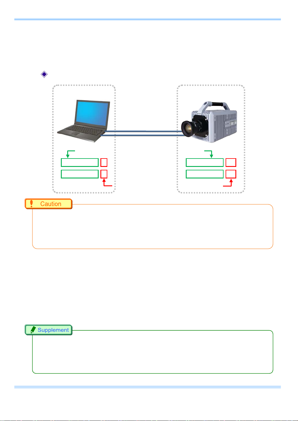
2. Confirming Camera System IP Address
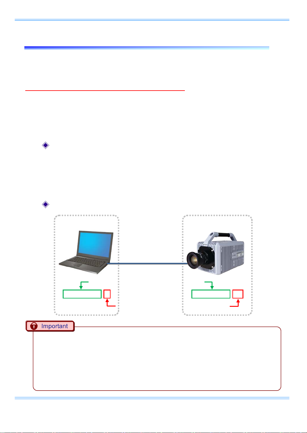
PC
High-speed camera
LAN cable
Use the same numbers up to the third segment
Set a different number for the fourth segment
192. 168. 0. 1
192. 168. 0. 10
2. Confirming Camera System IP Address
Confirm the IP address of the camera system by looking at the IP address label
placed on the camera (or processor) body.
Do not use this address for the settings on the PC.
If this address is used on the PC, then the camera and PC addresses will conflict
with each other, w hi ch may cause such issues as the PC not recognizing the
camera or live video not being displayed.
Please read “4. Network Settings on the PC (Manual)” for the PC settings.
Factory-default IP address
IP address : 192 . 168 . 000 . 010
Subnet mask : 255 . 255 . 255 . 000
Default gateway : 000 . 000 . 000 . 000
IP address example
Set the same numbers up to the third segment and use a different number in the fourth
•
segment for the IP address on the high-speed camera and the PC. The factory default for the
fourth segment of the camera's IP address is set to 10, so set a number on the PC other than
10 that is between 1 and 255.
When using two or more ca me r as, se t
•
other.
each
IP address so that they do not conflict with each
2 GigabitEthernet Interface Connected Manual

2. Confirming Camera System IP Address
When the IP address of t he hi gh-speed camera is changed and you don’t know it, a remote
•
control or a video monitor is necessary to recover the address. In this case, please contact our
technical support staff.
When the camera IP addr es s i s unknown, some specific high-speed camera m ode l c an re st or e
•
the default IP address only with the camera body. Please refer to the manual for detail.
3 GigabitEthernet Interface Connected Manual


3. Features of the Network Setting App
3. Features of the Network Setting App
i A message is displayed if the camera cannot be detected when the PFV
launches.
Note: Check [Do not show this again] to skip the display of this message
the next time it cannot communicate with the camera.
To display the message, check the [Network Setting App Alert] box
located under [Configuration]-[Alert] in the [Option] menu.
4 GigabitEthernet Interface Connected Manual

3. Features of the Network Setting App
ii Clicking [Yes] requires Administrator privileges to execute, so the
following message is displayed.
(The message is not displayed if the User Account Control is turned off.)
The following screen appears to enter each setting.
i
ii
iii
5 GigabitEthernet Interface Connected Manual

3. Features of the Network Setting App
i [Select LAN Port]
Select the adapter which is currently connected to the camera.
Only the number of adapters connected to the PC is displayed.
Be careful not to select an adapter that is not connected to th e camera.
Press [Refresh] to update to the current settings.
ii [Set the LAN port's IP address for connecting with cameras]
If the box is checked:
Specify the [IP Addr ess], [Subnet Mask], and the [Default Gateway]
shown in the frame.
If the box is not checked:
Use the DHCP connection without specifying the IP address information.
Press [Set] to update the settings.
Press [Reset] to return the IP addr ess setti ngs to the or iginal values w hen
the app launched.
iii [Setting an exception for the Windows Firewall]
If the box is checked:
Register “PFV” to the list of firewall exceptions.
If the box is not checked:
Delete “PFV” from the list of firewall exceptions.
Note: The list of exceptions is forcefully enabled and turned on when the
app launches.
Press the Close button when the settings are complete to display the
following message.
Reboot the PFV or the PC.
6 GigabitEthernet Interface Connected Manual

3. Features of the Network Setting App
The app can also be launched by starting the PFV and then selecting
[Network Setting app] under [Configuration] in the [Option] menu.
7 GigabitEthernet Interface Connected Manual

4. Setting PC
4. Network Settings on the PC (Manual)
4.1. Setting with Windows 7
i From the [Start] menu, click the [Control Panel], then click [View
network status and tasks].
ii Under Tasks located on the left-hand side of the window, click [Change
adapter settings].
8 GigabitEthernet Interface Connected Manual

4. Setting PC
iii Right click the [Local Area Connection] icon (when multiple Local Area
Connections exist, use the one with Gigabit Ethernet interface), and
select [Properties] in the popu p menu, the n [Local Area Connection
Properties] dialog will be displayed.”
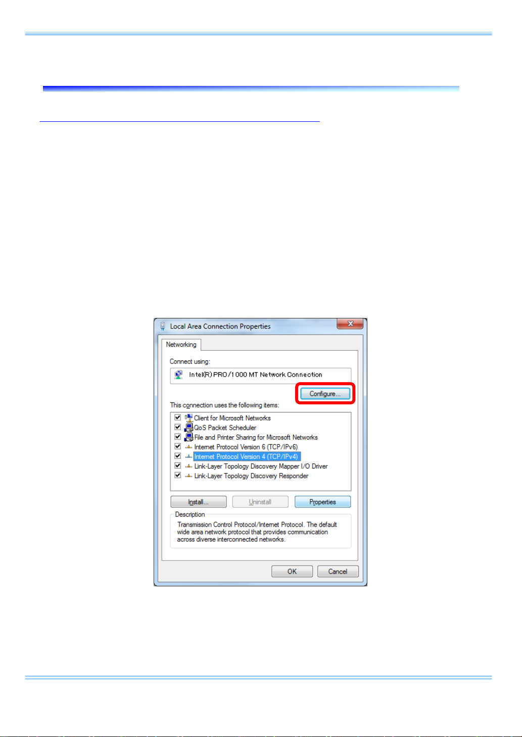
iv Select the [Internet Protocol Version4 (TCP/IPv4)] in the [Local Area
Connection Properties] dialog, then click the [Properties] button.
9 GigabitEthernet Interface Connected Manual

4. Setting PC
v From the [General] tab, verify that [Use the following IP address] is
selected. And set the [IP address] and [Subnet mask] as follows
respectively
1. IP address: 192 . 168 . 000 . 001
2. Subnet mask
There is no need to fill out [Default gateway]. The [Use the following DNS server address]
•
may be empty as well.
: 255 . 255 . 255 . 000
10 GigabitEthernet Interface Connected Manual
4. Setting PC
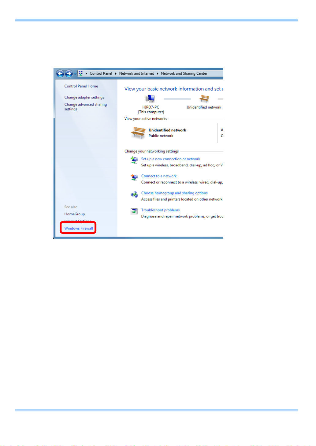
vi Click [OK], and then go back to the [View network status and task s] .
Select [Windows Firewall] this time.
11 GigabitEthernet Interface Connected Manual
4. Setting PC
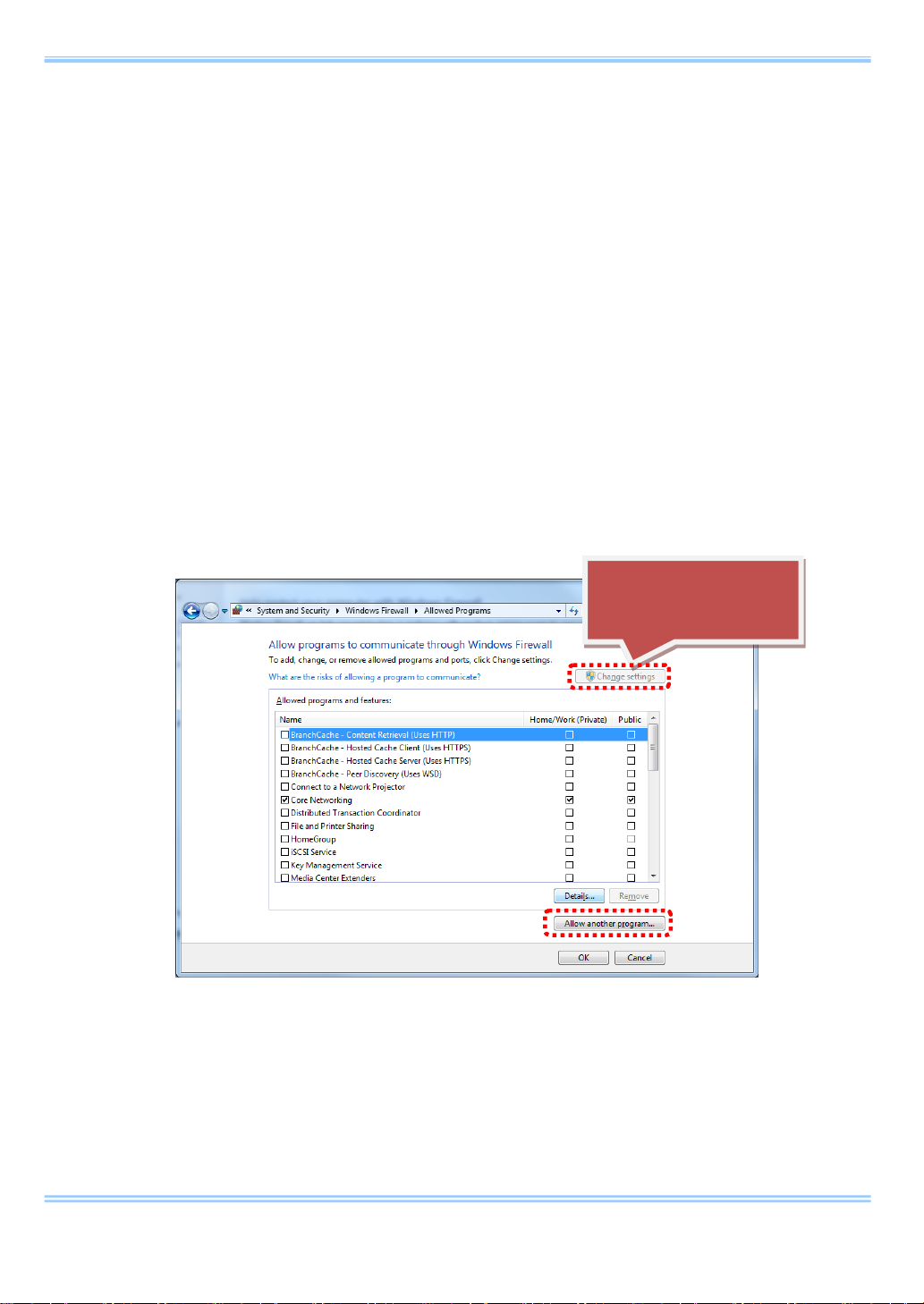
vii Then, select [Allow a program or feature through Windows Firewall].
viii Then, click [Change settings] button and [Allow another program...]
button.
12 GigabitEthernet Interface Connected Manual

4. Setting PC
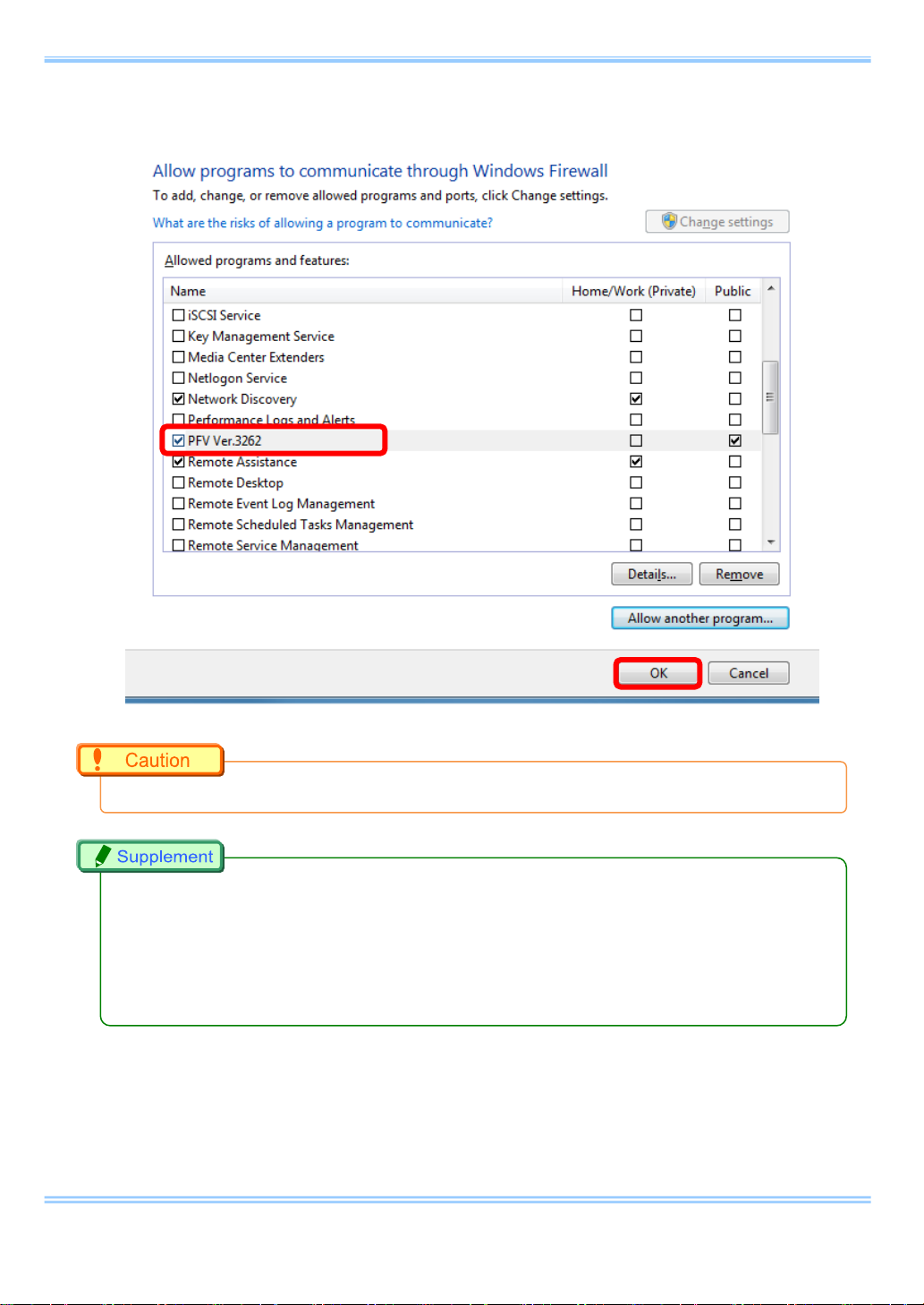
ix In the [Add a Program] dialog, select PFV and click [Add] button.
13 GigabitEthernet Interface Connected Manual
4. Setting PC
x Click the [OK] button to close the [Windows Firewal l].
The setting is necessary when the PFV version is updated.
•
It also does work when “Disable (Not recommended)” is selected. As the firewall is entirely
•
disabled in this case, it is not recommended.
If the PC has other security software firewalls, you may have to make the PFV exception for
•
each firewall. For information on the specific way of setting, refer to the relevant manual of the
security software.
14 GigabitEthernet Interface Connected Manual
4. Setting PC
4.2. Setting with Windows Vista
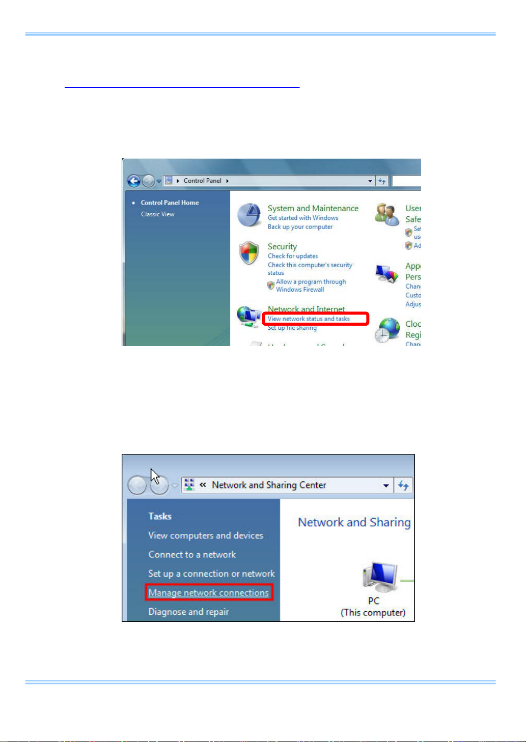
i From the [Start] menu, click the [Control Panel], then click [View
network status and tasks].
ii Under Tasks located on the left-hand side of the window, click [Manage
network connections].
15 GigabitEthernet Interface Connected Manual
4. Setting PC
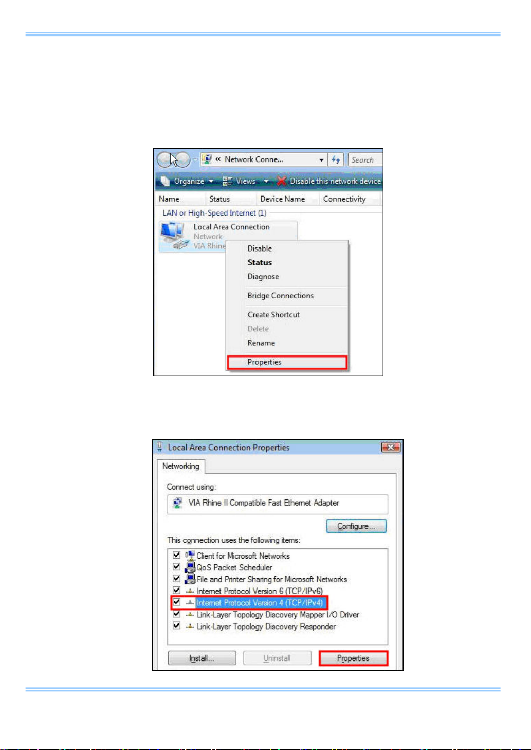
iii Right click the [Local Area Connection] icon (when multiple Local Area
Connections exist, use the one with Gigabit Ethernet interface), and
select [properties] in the popup menu, then [Local Area Connection
Properties] dialog wil l be displayed.
iv Select the [Internet Protocol Version4 (TCP/IPv4)] in the [Local Area
Connection Properties] dialog, then click the [Properties] button.
16 GigabitEthernet Interface Connected Manual
4. Setting PC
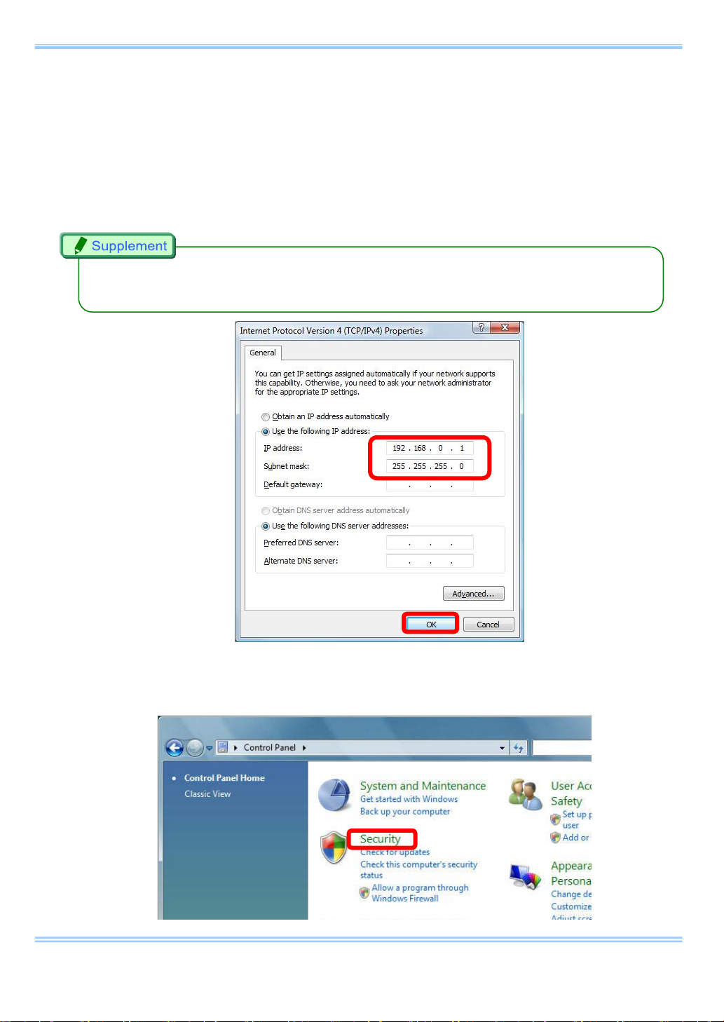
v From the [General] tab, verify that [Use the following IP address] is
selected. And set the [IP address] and [Subnet mask] as follows
respectively
1. IP address: 192 . 168 . 000 . 001
2. Subnet mask
There is no need to fill out [Default gateway]. The [Use the following DNS server address]
•
may be empty as well.
: 255 . 255 . 255 . 000
vi Click [OK], and then go back to the [Control Panel].
Select [Security] this time.
17 GigabitEthernet Interface Connected Manual

4. Setting PC
vii Then, select [Turn Windows Firewall on or off].
viii In the [Windows Firewall Setting] dialog, select the [On
(recommended)] radi o button. Note that [Block all incoming
connections] is unchecked.
18 GigabitEthernet Interface Connected Manual

4. Setting PC
xiv In the [Exceptions] tab, add PFV as an exception program.
19 GigabitEthernet Interface Connected Manual

4. Setting PC
The setting is necessary when the PFV version is updated.
•
It also does work when “Disable (Not recommended)” is selected. As the firewall is entirely
•
disabled in this case, it is not recommended.
If the PC has other security software firewalls, you may have to make the PFV exception for
•
each firewall. For information on the specific way of setting, refer to the relevant manual of the
security software.
xv Click the [OK] buttons to close the [Windows Firewall] and [Local
Area Connection Properties] dialogs.
20 GigabitEthernet Interface Connected Manual

5. Starting and Connecting Camera System
5. Starting and Connecting Camera System
i Connect between the camera system and PC with the provided LAN
cable.
ii Power the camera on.
iii Make sure that the [Link] LED on the camera system and that on the PC
(Ethernet) are on.
It may take about 30 seconds for the camera system to start up.
•
21 GigabitEthernet Interface Connected Manual

5. Starting and Connecting Camera System
Checking the FASTCAM MC2.1
22 GigabitEthernet Interface Connected Manual

5. Starting and Connecting Camera System
Checking the FASTCAM Mini UX50/100
23 GigabitEthernet Interface Connected Manual

6. Setting up PFV
6. Setting up PFV
i Start up the PFV.
ii Click [Option] => [Configuration].
iii Select the [Camera] item on the tree. Then make sure the applicable
camera is checked in the [Camera Interf a ce L ist ] and [Device List]
fields.
iv Click the [Setup] button on [Network Configuration] in the same dialog.
Then the [IP-address] dialog appears.
24 GigabitEthernet Interface Connected Manual
6. Setting up PFV
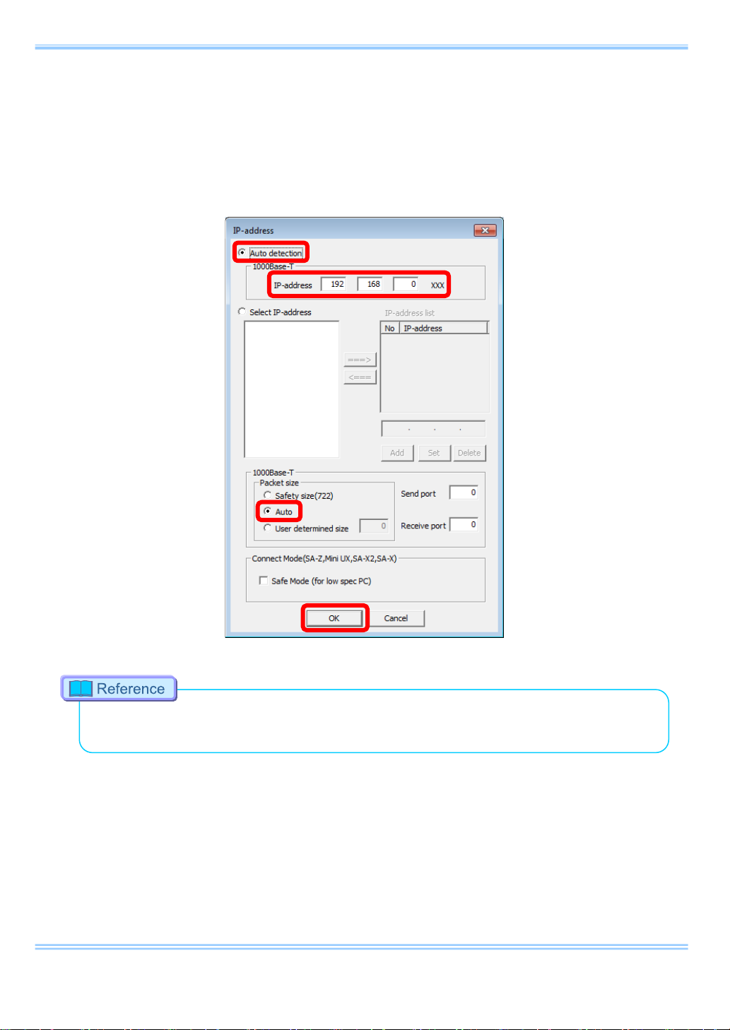
v Here is the easiest way:
1 ) Select [Auto detection].
2 ) Enter [IP-address] items 192.168.0.XXX.
3 ) Select [Auto] on the item [Packet size].
Refer to “7.1.3. Confir ming and Setting Camera IP Address” in “Photron FASTCAM Viewer
•
User’s Manual” for the details of the [IP-address] dialog.
vi Click the [OK] b u tto n and close the [IP-address] dialog.
vii The settings become effective when the PFV is restarted.
25 GigabitEthernet Interface Connected Manual
7. Setting “Jumbo Frame”
7. Setting “Jumbo Frame”
7.1. “Jumbo Frame” Settings in the OS
i Click [Start] => select [Control Panel] => [Ne twork Connection].
ii Select [Properties] on right-click menu of [Local Area Connection] (the
Gigabit Ethernet interface you are using if there are multiple), then the
[Local Area Connection Properties] dialog appears.
iii Confirm that the network adapter device 1000BASE-T and “Jumbo
Frame” compatible are shown on the [Connect using:] item. Click the
[Configure…] button, then open the properties of the network adapter.
26 GigabitEthernet Interface Connected Manual
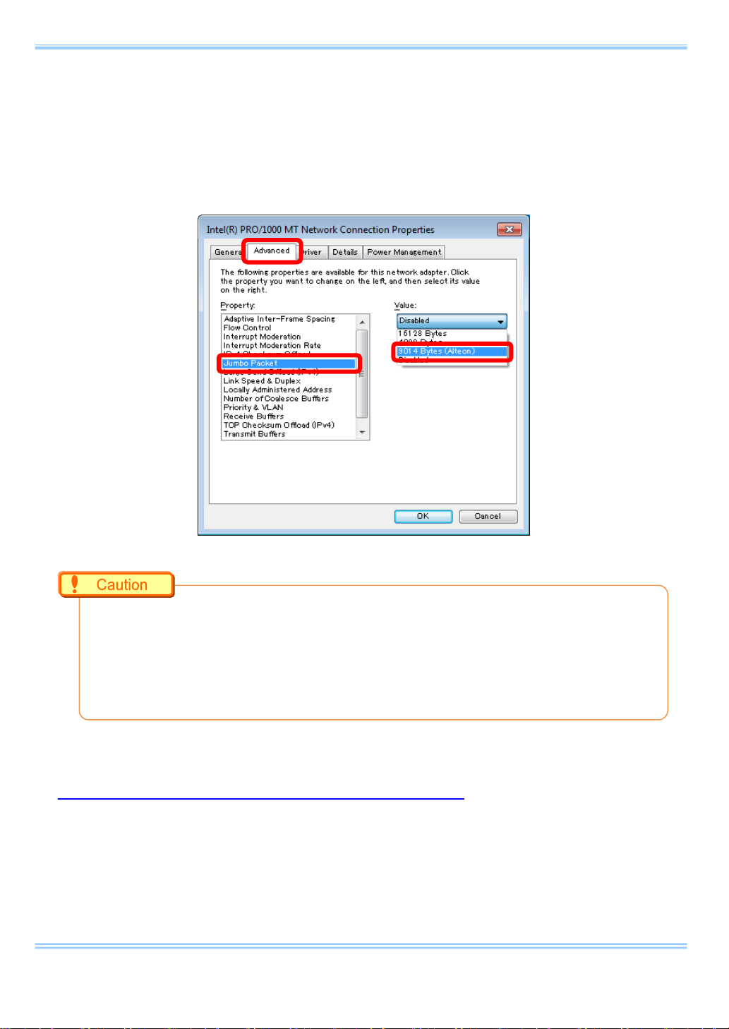
7. Setting “Jumbo Frame”
iv Click the [Advanced] tab, and set the [Jumbo Frames] (Jumbo Packet,
or something similar) item to the maximum allowable value.
The image shown below is an example of using a board which supports
the setting of “Jumbo Frames”.
Depending on the network adapter being used, the settings may be different from this
•
document.
Some network cards lack the “Jumbo Frame” feature.
•
The communication may be more stable in some network cards by not using the “Jumbo
•
Frame” feature.
7.2. “Jumbo Frame” Settings in the PFV
It is all right to just keep [Auto] on the [Packet size] item.
Keep [Send port] and [Receive port] “0 (zero)”.
27 GigabitEthernet Interface Connected Manual

8. Connecting the FASTCAM SA-X2 / SA-Z to the PC
8. Connecting the FASTCAM SA-X2/SA-Z to the PC
The Photron FASTCAM SA-X2/SA-Z high-speed cameras are equipped with two
Gigabit Ethernet interface connectors. They enable simultaneous use of both
connectors for high-sp eed downloads.
i Set the IP address on the PC. Please rea d “4. PC Network Settings
(Manual)” for the settings.
Please do not use the same IP address on the PC as the FASTCAM
SA-X2/SA-Z. If the SA-X2/SA-Z IP address is used on the PC, then the
SA-X2/SA-Z and PC addresses will conflict with each other, which may
cause such issues as as the PC not recognizing the camera or live video
not being displayed.
Factory default IP addr es s for the FASTCAM SA-X2/SA-Z
GIGABIT ETHER 1
IP address: 192 . 168 . 000 . 010
Subnet mask: 255 . 255 . 255 . 000
Default gateway: 000 . 000 . 000 . 000
GIGABIT ETHER 2
IP address: 192 . 168 . 001 . 010
Subnet mask: 255 . 255 . 255 . 000
Default gateway: 000 . 000 . 000 . 000
The SA-X2/SA-Z have two Gigabit Ethernet interface connectors, so there is an IP address for
•
each connector. Set an IP address for the PC that is different from both of these addresses.
28 GigabitEthernet Interface Connected Manual
8. Connecting the FASTCAM SA-X2 / SA-Z to the PC
PC
FASTCAM SA-X2
LAN cable
Use the same numbers up to the third segment.
192. 168. 0. 1
192. 168. 0. 10
192. 168. 0. 1
192. 168. 0. 10
Set a different number for the fourth Segment.
ii Insert two LAN cables into the Gigabit Ethernet interface connectors to
connect the camera and the PC. The connectors on the rear of the SA-X
are labeled “GIGABI T ETHER 1” and “GIGABIT ETHER2”.
IP address setting example
Refer to the FASTCAM SA-X2/SA-Z hardware manual for details about how to connect the
•
camera.
Different PCs cannot be connected to “GIGABIT ETHER1” and “GIGABIT ETHER2” and
•
operated.
iii Turn on the camera's power supply. Confirm that the SA-X2/SA-Z LINK
LED and the PC (Ethernet) LINK LED are lit up. The “GIGABIT ETHER1”
Link LED on the SA-X2/SA-Z corresponds to “IF1 LINK/TRANS” and the
“GIGABIT ETHER2” to “IF2 LINK/TRANS”.
iv Start the PFV.
When high-speed downloading using both Gigabit Ethernet connections is enabled, the LEDs
•
for “IF1 LINK/TRANS” and “IF2 LINK/TRANS” flash during dow nloads. I f one of th e LED s i s not
flashing, then high-speed downloading may not be enabled. Refer to “10. Troubleshooting” for
more details.
29 GigabitEthernet Interface Connected Manual

9. Troubleshooting
9. Troubleshooting
If the live images ar e n ot dis played even when th e camera and PC ar e c onn ect e d
with a LAN cable and the PFV is running, then there may be a problem with the
connection between the camera and the PC.
Please check the following items.
i. Check that the camera's LINK LED lights up.
If the LED is not lit up, check the LAN cable connection/disconnection or
dirty connectors. In addition, the network device may not support Gigabit
communication or the interface board on the camera may be defective.
ii. Check the IP address on the PC.
The same IP address may be set on the camera and the PC. The factory
default for the camera's IP address is 192.168.0.10. The address set on
the PC must use the same numerical values up to the third segment but a
different number for th e f ourt h s egment (basical ly, the address must be the
same up to 192.168.0).
Check the IP address on the PC using the following procedure (on
Windows 7).
1. From the [Start] menu, select [Control Panel ] -> [Network and Sharing
Center].
30 GigabitEthernet Interface Connected Manual

9. Troubleshooting
2. Click [Change adapter settings] in the upper left of the screen.
Right-click the displayed [Local Area Connection] and select
[Properties]. Double-click [Internet Protocol Version 4] i n the middle of
the displayed window to check the IP address.
3. If the IP address displayed here is set to 192.168.0.10, the same
address may be set on both the PC and the camera. Change the
number for the fourth segment of the IP address to a number other
than 10 (between 1 and 255; e.g., 192.168.0.1).
31 GigabitEthernet Interface Connected Manual
9. Troubleshooting
iii. Check the Windows Firewall settings.
Communication between the camera and the PFV may be blocked by the
Windows Firewall. The PFV must be registered to the list of programs that
are allowed access by the firewall.
Use the following procedure to register the PFV in the list of allowed
programs (for Windows 7).
1. From the [Start] menu, select [Control Panel ] -> [Network and Sharing
Center]. Click [Windows Firewall] in the lower left of the screen.
2. Select [Allow a program or feature through Windows Firewall] in the
upper left, click the [Change settings] button in the upper right -> click
[Allow another program].
Does not need to be
clicked in some cases.
32 GigabitEthernet Interface Connected Manual

9. Troubleshooting
3. Select [PFV VerXXX] in the list of programs displayed in the [Add a
Program] window and click the [Add] button to register.
33 GigabitEthernet Interface Connected Manual

9. Troubleshooting
iv. Automatically search for the camera with PFV.
The PFV includes a feature to aut omatic ally searc h for the speci fied IP addr ess.
Check the feature settings with the following procedure.
1. Start the PFV and then select [Configuration] from the upper [Option]
menu.
2. Confirm that the interface you are using is checked under the [Camera
Interface List]. Also confirm that the camera you are using is checked
under the [Device List]. If these items are not checked, please check
them now.
Please note that new models added by PFV version
updates are initially unchecked.
34 GigabitEthernet Interface Connected Manual

9. Troubleshooting
3. Click the [Setup] button under [Network Configuration] in the
[Configuration] window to display the [IP-address] settings window.
Confirm that [Auto detection] is checked. The IP address displayed
below that item is the IP address used to automatically search for the
camera.
35 GigabitEthernet Interface Connected Manual

9. Troubleshooting
v. Use a command prompt to check the connection between the camera
and the PC.
Run a Ping command from the command prompt to check that the connection
between the camera and the PC is not being blocked. Use the following
procedure to execute the Ping command.
1. From the [Start] menu, open [Accessories] -> [Command Prompt].
2. Input “ping 192.168.0.10” and press the Enter key.
3. If the following type of response is displayed, the camera and the PC
are connected. If the live images are still not displayed on the PFV
under these conditions and there is no change, then there is a
possibility that it is being blocked by the firewall. Refer to procedure iii
or procedure viii.
4. If the following type of response is displayed, the camera and the PC
are not connected. Check the LINK LED with procedure i and the IP
address with procedure ii.
36 GigabitEthernet Interface Connected Manual

9. Troubleshooting
vi. Check the [User Account Control] settings.
Some manufacturer's PCs are unable to properly connect unless the [User
Account Control] feature is turned off. Use the following procedure to turn
off the [User Account Cont rol ] feature.
1. From the [Start] menu, open [Control Panel] -> [User Accounts] and
select [Change User Account Control settings].
2. Move the left slider in the displayed window all the way to the bottom.
The PC must be restarted after the settings are changed.
37 GigabitEthernet Interface Connected Manual

9. Troubleshooting
vii. Check the packet size.
The packet size may be restricted for some reason. The PFV has a feature
to change the packet size. Use the following p r ocedur e to check th e pack e t
size.
1. Start the PFV and then select [Configuration] from the upper [Option]
menu.
2. Click the [Setup] button under [Network Configuration] in the
[Configuration] window to display the [IP-address] settings window.
Check the [Safety size] item u nder [Packet siz e] i n the lower part of the
window.
viii. Check any third-party firewall settin g s.
Communication between the camera and the PFV may be blocked by
third-party firewalls. After checking the Windows Firewall settings with
procedure iii, check the settings of any third-party firewalls.
38 GigabitEthernet Interface Connected Manual

9. Troubleshooting
ix. Check the following points when using the FASTCAM SA-X2/SA-Z.
Please note the following points regarding the LAN connection and the IP
address when using the Photron FASTCAM SA-X2/SA-Z high-speed
camera. Check the following points in addition to procedures i to viii.
Th e FAS TCAM SA-X2/SA-Z includes two Gigabit Ethernet interface
connectors. Note that the factory default for the IP address of
“GIGABIT ETHER2” is set to “192.168.1.10”.
Confirm the LAN connection interface. The connection may not work
well or be unstable when connecting to the LAN with a PCI board,
PCMCIA card, or USB-LAN unit.
Th e FAS TCAM SA-X2/SA-Z can connect using two LAN cables. For
this reason, there are two IP addresses, but only one IP address
should be specified for the PFV connection setting. If both IP
addresses are specified, then they will be recognized as two separate
cameras.
39 GigabitEthernet Interface Connected Manual

9. Troubleshooting
x. Check the following points after checking procedures i through ix.
Check that the NIC (LAN board) supports Gigabit Ethernet. Car ds t hat onl y
support 10/100 Base cannot connect. It is possible to route through a
Gigabit Ether switching hub, but the communication will be slower.
Check that you are not using a wireless LAN. The wireless LAN may be
searched when searching the network, so try setting the wireless LAN to
“Disable”.
Check to see if the terminal that is set is different from the LAN terminal
you are using. Please be careful if there are two or more local area
connections shown on the Windows network connections screen.
In some cases the camera's IP address may have changed (the camera's
factory default IP address is “192.168.0.10”). In this case, you need to
connect the optional remote controller to confirm and change the address.
Some models may be reset. Please contact our engineering manager
regarding the supported models.
Connect the camera head when using the FASTCAM MC2 / MC2.1 / MH4.
When two or more cameras or PCs connect through a hub, the devices
may have the same IP addr ess and b e unabl e to co nnec t. Set a di ffer ent IP
address for each device.
Confirm that the camera cable is Enhanced Category 5 or higher.
If the issue is still unresolved after performing pr o cedur es i through x, please contact our
•
engineering manager. Pl eas e also inq uire a bout any poi nts t hat ar e u nc lear i n each procedure.
40 GigabitEthernet Interface Connected Manual

10. FAQ
10. FAQ
Q.1.
Is a driver required for Gigabit Ethernet interface, as is the case with IEEE1394
and optical interface systems?
A.1.
No, it is not necessary to install any driver because communication takes place
via the TCP/IP Ethernet connection.
Q.2.
What is “Jum bo Frame”?
A.2.
A frame that is bigger than the standard maximum frame size of Ethernet
(1,518 byte) is called a “Jumbo Frame” or “Jumbo Packet”.
When a “Jumbo Frame” is activated, the maximum size of data to be sent at
one time becomes bigger and the actual data transfer speed (throughput) is
increased.
To use the Jumbo Frame function, all devices are required to be compatible
with Jumbo Frame, not only the devices on both sides, which communicate each
other, but also other network devices like the network hub.
41 GigabitEthernet Interface Connected Manual

10. FAQ
Q.3.
What is the difference between simply selecting [Auto detection] and
selecting [Select IP-address] to register each IP address on [IP-address
dialog]?
A.3.
There may be some difference in the startup time when starting up the PFV
application. When [Auto Detection] is selected, the application looks for
applicable camera systems by the IP address, which takes a little more time.
You can control only the specified camera(s), if there are several camera
systems on the Network, if the IP address of each camera is registered.
On the other hand, if the network has a DHCP server in it, which assigns IP
addresses for all devices in the network, the IP addresses assigned to cameras
may be changed every time they are connected to the network, and the PC is
required to be set in the [Auto detection] mode in advance to find the camera
systems.
Q.4.
Is it possible to use the camera systems by connecting them to an existing
1000BASE-T network? Is it also possible to control the cameras in a WANconnected network (e.g., controlling a camera remotely from other locations)?
A.4.
It is technically possible but we do NOT recommend it because of possible
security issues involved. Please note there is NO assurance of security.
We only recommend using the camera system in a closed network.
Please contact our engineering manager r eg ar di ng c ases i n which you connect
multiple PCs and cameras.
42 GigabitEthernet Interface Connected Manual

10. FAQ
Q.5.
How can multiple camera systems be connected to one PC?
A.5.
Multiple cameras can be connected to one PC by splitting the cables through a
hub and assigning a unique IP address to each camera. However, the hub must
be 1000BASE-T compatible. In addition, if you wish to use the “Jumbo Frame”
function, the hub must also be compatible with the function.
Q.6.
Camera is not recognized by the software when starting up the PFV
application.
A.6.
Try to read the applicable hardware manual well, such as the PFV manual and
this document. Many possible causes are considered.
One typical cause may be that, at the first time the PC is connected to the
camera system, the Firewall of Windows 7 may block the connection.
Another cause may be that, even thought the PFV software seems to be
reacting correctly, the image presents some problem. Choosing [Safety Size
(722)] may possibly solve the problem.
43 GigabitEthernet Interface Connected Manual

Items Verified
Concrete Example
Contact e-mail.
Condition of the system and what is known about it.
11. Contacting Photron
11. Contacting Photron
For inquires related to this manual, contact Photron at the contact information listed below.
Additionally, the following items will be verified when inquiring, so please prepare them in
advance.
Company, school or organization name,
Contact
Information
In Americas
and Antipodes
customer contact name,
contact phone number,
Contact Information
PHOTRON USA, INC.
9520 Padgett Street, Suite 110
San Diego, CA 92126-4426, USA
Phone : 800-585-2129 or 858-684-3555
Fax : 858-684-3558
E-mail : image@photron.com
www.photron.com
PHOTRON EUROPE LIMITED
The Barn, Bottom Road,
West Wycombe, Buckinghamshire,
In Europe,
Africa and India
HP14 4BS, U.K.
Phone : +44(0) 1494 48 1011
Fax : +44(0) 1494 48 7011
E-mail : image@photron.com
www.photron.com
PHOTRON LIMITED
21F, Jimbocho Mitsui Bldg.,
1-105 Kanda Jimbocho, Chiyoda-Ku, Tokyo 101-0051
In other areas
Phone : +81 3 3518 6271
Fax : +81 3 3518 6279
E-mail : image@photron.co.jp
www.photron.co.jp
44 GigabitEthernet Interface Connected Manual

GGiiggaabbiittEEtthheerrnneett IInntteerrffaaccee
Connected Manual Revision 1.20E
Publication Date March 2017
Publisher PHOTRON LIMITED
21F, Jimbocho Mitsui Bldg.,
1-105 Kanda Jimbocho, Chiyoda-Ku, Tokyo 101-0051
©2017.PHOTRON LIMITED, All rights reserved. Printed in Ja pan.
(Control No. J170330U)
 Loading...