


FASTCAM MH6
Hardware Manual

The copyright of this manual is held by PHOTRON LIMITED.
Product specifications and manual contents are subject to change without notice.
PHOTRON LIMITED bears no responsibility for any results by using our products nor by applying this manual to any operations.
WARNING
This equipment has been tested and found to comply with the limits for a Class A digital device,
pursuant to part 15 of the FCC Rules. These limits are designed to provide reasonable protection
against harmful interference when the equipment is operated in a commercial environment. This
equipment generates, uses, and can radiate radio frequency energy and, if not installed and used in
accordance with the instruction manual, may cause harmful interference to radio communications.
Operation of this equipment in a residential area is likely to cause harmful interference in which case
the user will be required to correct the interference at his own expense.
CAUTION:
Any changes or modifications not expressly approved by the party responsible for compliance could
void the user's authority to operate the equipment.

Introduction
Introduction
Thank you for your purchase of Photron’s high-speed camera system, the “FASTCAM MH6”
(referred to below as the system).
This manual contains the operating instructions and warnings necessary for using the system.
Before using the system, please read the entire manual.
If any part of this manual is unclear, contact Photron using the contact information printed at
the back of the manual.
After you finish reading the manual, store it in a safe place along with the warranty card and
refer back to it when necessary.
l

Using the Manual
Using the Manual
This section explains the layout of the manual.
Introduction
The introduction explains the manual and safety precautions.
Chapter 1, Setup
This chapter gives an overview of the components that make up the system. It also explains basic keypad
operation and a list of items that should be checked before using the system.
Chapter 2, Recording
This chapter explains operations related to recording.
Chapter 3, Product Specifications
This chapter explains the system’s specifications.
Chapter 4, Product Specifications
This chapter explains about the warranty.
Chapter 5, Contacting Photron
This chapter lists the contact information to use when contacting Photron if the system malfunctions or if a portion
of the manual is unclear.

Manual Notation
Manual Notation
The following icons and symbols are used in the explanations in this manual.
Icon/Symbol
Description
This symbol indicates supplementary items to be aware of
when using the software.
This symbol indicates the location of a reference.
This symbol indicates content that should always be read.
This symbol indicates instructions that should always be
followed when using the software, or things to be careful of
when using the software.
" "
This symbol is used to indicate the names of items on a
screen, references, dialog names, and connectors.
[ ]
This symbol is used to indicate menu names, and sub-
menu names.

Using the System Safely and
Correctly
Using the System Safely and Correctly
In order to prevent injury to yourself and others, and to prevent damage to property, carefully
observe the following safety precautions.
Photron has given its full attention to the safety of this system. However, the extent of damage
and injury potentially caused by ignoring the content of the safety precautions and using the
system incorrectly is explained next. Please pay careful attention to the content of the safety
precautions when using the system.
This symbol indicates actions that carry the risk that a person could receive a
serious injury.
This symbol indicates actions that carry the risk that a person could receive a
moderate injury, or that damage to physical property might occur.
The safety precautions to be observed are explained with the following symbols.
This symbol indicates actions that require caution.
This symbol indicates actions that are prohibited and must be avoided.
This symbol indicates actions that must always be performed.
Caution
Warning

Using the System Safely and Correctly
■Do not perform actions that will damage the AC cable or plug.
(Do not damage the cable, modify it, use it near a heater, excessively bend, twist or
pull on it, place heavy objects on it, or bundle it.)
Using the cable when damaged can cause fire, electric shock, or a short circuit.
■Do not use the system in a manner which will exceed the rating of the power
outlet or wiring equipment used.
Exceeding the power rating might cause a fire from excessive heat.
■Do not insert metallic objects inside, or pour liquids such as water on, the system.
Doing so can cause fire, electric shock, or malfunction from short circuit or heat.
■Do not disassemble or modify the system.
There are high voltages inside the system that can cause electric shock.
■Do not plug in or unplug the power cord with wet hands.
Doing so can cause electric shock.
■Make sure the power plug is fully insert into the socket
Not fully plugging in the power cable can cause fire from electric shock or heat.
■When something is wrong with the system, unplug the power cable immediately.
- When a foreign substance or liquid, such as metal or water, gets inside.
- When the outer case is broken or damaged, such as from a fall.
- When the system produces smoke, a strange smell, or strange sound.
Using the system in these conditions might cause a fire or electric shock.
■Do not use the accessories by the usage that a manufacturer does not specify. It
may cause damage of protection.
Warning

Using the System Safely and Correctly
■Always unplug the system when cleaning it or when it is unused for a long period
of time. Leaving or storing the system connected to the power source might cause
fire from insulation deterioration or electrical discharge.
■Please consult us in advance when you perform an event by which laser light or
direct rays fall on the image sensor surface.
■Do not set the system in a location where the temperature gets unusually hot.
The trunk and inside of a car can get especially hot in summer.
Doing so can cause the outer case and internal components to deteriorate or cause a
fire.
■Do not place the system in a location prone to oily smoke or steam, or in a location
with a lot of humidity or dust.
Oil, moisture, and dust conduct electricity, which can cause a fire or electric shock.
■Ambient temperature 0-45°C, humidity 80% RH or lower, maximum altitude
2,000m or lower. In addition, if exceeding these limits, use in a condensation-free
environment.
Use in a condition out of the above limits can cause malfunction.
■Do not store the equipment in a location where the temperature goes below -20°C
or higher than 60°C. Also, prevent condensation from forming during shipment.
■When shipping, remove the connecting cable and use the original packaging or a
dedicated carrying case.
Do not ship the equipment in an environment where the temperature goes below 20°C or higher than 60°C. Also, prevent condensation from forming during
shipment.
Caution

Using the System Safely and Correctly
■When installing the camera with a tripod, please check the tripod load capacity and
be careful not to exceed the load bearing capacity.
Also, when using a tripod, please make sure that the tripod, tripod screw, panhead,
and others are properly set, and be careful not to fall down the tripod
Caution

Using the System Safely and Correctly
“CE” mark indicates that this product complies with the European requirements for safety,
health, environment and customer protection. “CE” mark equipments are intended for sales in
Europe.
These symbols indicate that this product is not to be disposed of with your household
waste, according to the WEEE Directive (2002/96/EC), the Battery Directive
(2006/66/EC) and/or your national laws implementing those Directives.
This product should be handed over to a designated collection point, e.g., on an
authorized one-for-one basis when you buy a new similar product or to an authorized
collection site for recycling waste electrical and electronic equipment (EEE) and
batteries and accumulators. Improper handling of this type of waste could have a
possible impact on the environment and human health due to potentially hazardous
substances that are generally associated with EEE. Your cooperation in the correct
disposal of this product will contribute to the effective usage of natural resources.
For more information about the recycling of this product, please contact your local
city office, waste authority, approved scheme or your household waste disposal
service or visit www.photron.com.
(EEA: Norway, Iceland and Liechtenstein)
This product is in conformity with the protection requirements of EU Council Directive
2014/30/EU (Class A) on the approximation of the laws of the Member States
relating to electromagnetic compatibility.
Warning: This is a Class A product. In a domestic environment, this product may
cause radio interference, in which case the user may be required to take adequate
measures.
European Union (and EEA) only

Using the System Safely and Correctly
Electrostatic Discharge (ESD) events may cause immediate and unrecoverable damage to the image sensor.
Please read the following instructions and take EXTREME CARE when cleaning the image sensor surface.
■ALWAYS take appropriate anti-static precautions when cleaning or working near
the Image sensor.
■DO NOT use any form of cleaning equipment using electrostatic or ‘charged fiber’
technology.
◼ Please discharge any electrostatic build up in your body by touching a grounded
metallic surface before working near the camera sensor.
◼ Very gently, use only clean and dry air to remove dust from surface of the image
sensor.
◼ To remove stubborn contamination use the highest grade (e.g. VLSI grade) pure
Isopropyl alcohol (IPA) with optical wipes of “clean room” grade.
◼ Extreme care must be taken! Gently wipe across the sensor in a single action.
(DO NOT rub to avoid abrasive damage to delicate optical coatings on the glass
surface.)
Cleaning of the Image Sensor Surface

Contents
Contents
Setup 1
1.1. About the System’s Components and Accessories ................................. 2
1.1.1. Components .......................................................................... 2
1.1.2. Accessories/Options ............................................................... 2
1.1.3. Type ..................................................................................... 3
1.2. Part Names .................................................................................... 4
1.2.1. Main Unit .............................................................................. 4
1.2.2. Main Unit Part Names ............................................................. 5
1.2.3. CameraHead ........................................................................ 6
1.2.4. CameraHead+Bracket ........................................................... 7
1.2.5. Gigabit Ethernet Connector .................................................... 11
1.2.6. VDA_TRIG SYNC Circuit Diagram ........................................... 14
1.2.7. IO INPUT_IF Circuit Diagram ................................................. 15
Recording 16
2.1. Selecting Frame Rate/ Resolution ..................................................... 17
2.2. Selecting Shutter Speed .................................................................. 18
Product Specifications 19
3.1. Specifications ............................................................................... 20
3.1.1. Product Specifications .......................................................... 20
3.1.2. General Specifications ........................................................... 21
3.1.3. Frame Rate and Resolution .................................................... 22
3.1.4. Shutter Speed List ................................................................ 23
3.1.5. Shutter Speed List ................................................................ 23
3.2. Dimensions .................................................................................... 25
3.2.1. Main Unit ............................................................................ 25
3.2.2. Main Unit with Hi-G Brackets ................................................. 26
3.2.3. CameraHead ........................................................................ 27
3.2.1. CameraHead with Hi-G Bracket .............................................. 28
3.2.1. Hi-G Bracket ........................................................................ 29

Contents
3.2.1. Power Supply Unit ............................................................... 32
3.2.2. I/O 2 PORT Cable ................................................................. 32
Contacting Photron 33
4.1. About the Warranty ........................................................................ 34
Contacting Photron 35
5.1. Contact Information ........................................................................ 36
A. Appendix 37
A.1. Reference Information ................................................................... 38
A.1.1. Relative Spectral Response (monochrome) ............................. 38
A.1.2. Relative Spectral Response (color) ........................................ 38

1
Setup
This chapter gives an overview of the
components that make up the system. It
also explains a list of items that should
be checked before using the system.

2
FASTCAM MH6
1.1 About the System’s Components and Accessories
About the System’s Components and Accessories
1.1.1. Components
Refer to the attached packing list for this product's standard components and
accessories.
1.1.2. Accessories/Options
The following options are available for the system.
1. Hi-G Bracket for MH6 Main Unit
2. Hi-G Cable Fix Handle for MH6 Main Unit
3. Camera Cable for MH6 (9m/6m)
4. Cable Removal Prevention Cap
5. Connection Cable for Hi-G Battery (7m/3m)
6. Hi-G Battery (32V type/24V type)
7. FASTCAM MH6 Specialized Carrying Case
•
The composition of cables turns into composition chosen at the time of purchase.

3
FASTCAM MH6
1.1 About the System’s Components and Accessories
1.1.3. Type
For the camera head, there are monochrome and color versions.
And for the system, there are 6ch of camera head ports.
When purchasing, it is possible to select the Camera head type and the number of
heads according to the application or your demands.
The type categories are listed as follows.
.
◼ Camera head type name and category
Item
list
Explanation
Fame Rate
10K
10,000fps
Censor
M
monochrome
C
color
FASTCAM MH6 Camera Head type 10K-C
Censor
Camera Name
Frame Rate

4
FASTCAM MH6
1.2 Part Names
Part Names
The system is composed of components including the Main Unit, Camera Head, AC Power
Supply Unit, and the "Photron FASTCAM Viewer" controls software (referred to below as
PFV).
For the camera body and the AC power adapter
- Do not expose the camera body, AC power adapter and other optional
components to shock.
- Do not use in an area where flammable gas or dust is present.
- Do not place in an unstable location such as on an unstable platform or an
incline.
- Do not disassemble or modify.
- Do not expose to liquids such as water.
- Do not subject to excessive force.
1.2.1. Main Unit
The system has 100G of Hi-G capability and can connect a camera head of up to 6ch.
Although the memory capacity per camera head is 4GB, a maximum of 24GB capacity
with one camera head can be used by sharing memory.
Main Unit

5
FASTCAM MH6
1.2 Part Names
1.2.2. Main Unit Part Names
MH6 Main Unit
Camera Connector
USB 3.0
USB 3.0 Connector
POWER
Power Switch
USER
USER SW1~4
Status Indicator LED
KEYPAD
Remote keypad Connector
I/O PORT 2
I/O Port Connector
I/O PORT 1
I/O Port Connector
Gigabit Ethernet Connector
DC22-32V 135VA IN
Power Supply Connector

6
FASTCAM MH6
1.2 Part Names
1.2.3. CameraHead
本製品のカメラヘッドは、解像度 1,920x1,400、撮影速度 10,000fps 撮影が可能です。
カメラヘッドはカラー/モノクロタイプのヘッドが選択できます。
また、1台の Main Unit に対し複数接続可能なカメラヘッドは、共通の同期信号にて動作するため、1つの
現象を様々な角度から同時撮影することが可能です。
• Since the camera head is not compatible with hot plug, please remove it before turning off the
main power. Please note that it will cause malfunction if you turn the power on.
Camera Head

7
FASTCAM MH6
1.2 Part Names
1.2.4. CameraHead+Bracket
The system is available as standard with a Hi-G camera / lens bracket.
Since the camera head becomes hot, be sure to attach the Hi-G camera / lens
bracket or a fixture that can ensure equivalent heat dissipation performance.
A different Hi-G lens Bracket is prepared for each lens.
Please use the Hi-G lens bracket corresponding to each lens.
Lenses corresponding to the following brackets LM6HC:KOWA

8
FASTCAM MH6
1.2 Part Names
◼ Camera head with Hi-G Bracket
Below is an example of the procedure for attaching the camera head bracket.
2. Use M3 x depth6 hex socket cap bolts to attach to the left and
right sides.
3. Use M3 × depth6 flat head screws on top.
1. Paste gasket.

9
FASTCAM MH6
1.2 Part Names
5. Use M4 × depth10 hex socket cap bolt and M4 × depth10 hex
socket cap bolt.
M4×10 hex socket cap bolt
M4
×
10 hex socket cap bolt
with M4 washer
6. Use knurled screw and M3 × depth4 bind (both sides) to install
the parts.
Knurled screw
M3×4 bind
Completion
4. Attach four screws with M3 x depth8 hex socket cap bolts and
assemble the bracket to be attached to the side.

10
FASTCAM MH6
1.2 Part Names
◼ Main Unit with Hi-G Bracket
◼ Hi-G Cable Fix Handle

11
FASTCAM MH6
1.2 Part Names
1.2.5. Gigabit Ethernet Connector
It is an Ethernet connector for communicating with the PC and is a common RJ45
connector.
Connect a 1000BASE-T compatible interface board and this product with a LAN cable.
For the LAN cable, prepare a UTP or STP Cat 5e (enhanced category 5) or higher LAN
cable. (UTP: Unshielded Twisted Pair, STP: Shielded Twisted Pair)
To connect a PC to the system, connect the system to a commercially available
1000BASE-T-compatible interface board with a LAN cable. For the LAN cable, prepare a
UTP or STP CAT5E (enhanced category 5) or higher LAN cable. (UTP: unshielded, STP:
shielded)
The maximum cable length between the PC and the system is, compliant to the
1000BASE-T specification, up to 100 m. One PC can connect to a maximum of 64 Photron
Gigabit Ethernet interface equipped cameras using a hub. When connecting multiple
devices, connect through a switching hub that can connect at 1000BASE-T. The maximum
length of the cable that connects the system (or PC) to the switching hub is also 100 m.
I/O1 ピン配置
13
17
16
15
12
1
11
10
9
8
7
6
5
4
3
2
18
14
ECJ.2B.318.CLN

12
FASTCAM MH6
1.2 Part Names
I/O1 Connector (German automobile required connector) pin assignment
Pin Signals
Color (recommend)
Description
1
Eth A-
Orange
Pair 2 Wire 2
2
Eth D-
Brown
Pair 4 Wire 2
3
Eth B-
Green
Pair 3 Wire 2
4
Eth B+
Green White
Pair 3 Wire 1
5
Eth C+
Blue
Pair 1 Wire 2
6
General Out
Red AWG30
Ready/Sync … out rising+/falling-
7
CAM Sup +
Orange
24V
8
CAM Sup +
Red
24V
9
Sync R(rising+)
Yellow AWG30
RS485+
10
Sync F(falling-)
Green AWG30
RS485-
11
CAM Sup -
Grey
GND
12
CAM Sup -
Black
GND
13
Eth A+
Orange White
Pair 2 Wire 1
14
Eth D+
Brown White
Pair 4 Wire 1
15
Eth C-
Blue White
Pair 1 Wire 1
16
General Out
Brown AWG30
Ready/Sync … out rising+/falling-
17
Trig F(falling -)
White AWG30
RS485-
18
Trig R(rising +)
Brown AWG30
RS485+
shell
Shield
Setting items
■ System side
■ PC side
・IP address setting
・IP address setting
・Packet size
・Timeout time
・Send/Receive port
•
When using the above signals, it is necessary to create a cable with reference to the
table.
•
Sync R, Sync F, Trig R, Trig F has no termination.
•
Sync R, Sync F can be single input.
•
For other details, please contact our technical staff.

13
FASTCAM MH6
1.2 Part Names
•
Photron recommends using an STP cable over long distances or in noisy locations.
•
The system's factory default IP address is below:
IP ADDRESS : 192.168.0.10
NETMASK : 255.255.255.0
GATEWAY ADDRESS : 0.0.0.0

14
FASTCAM MH6
1.2 Part Names
1.2.6. VDA_TRIG SYNC Circuit Diagram
n
n
1
2
3
4
5
6
7
8
D
G
S
V C C
R O
Y
Z
A
B
D I
G N D
B L M 1 8 P G 4 7 1 S N 1
1 6 0 8 , 4 . 7 k , 1 %
1 0 0 5 , 0 . 1 u , 5 0 V
V D D _ + 3 . 3 V
1 6 0 8 , 4 . 7 k , 1 %
1 6 0 8 , 1 k , 1 %
V D D _ + 5 V
1 6 0 8 , 1 k , 1 %
M A X 3 4 9 0 A E G S A +
2 N 7 0 0 2 E T 1 G
1 0 0 5 , 2 2 0 , 1 %
1 0 0 5 , 2 2 0 , 1 %
2 N 7 0 0 2 E T 1 G
DGS
S Y N C _ D I F F _ i
n ( 未 使 用 )
V D D _ + 3 . 3 V
1 0 0 5 , 4 . 7 k , 1 %
S Y N C _ F _ i
S Y N C _ R _ i n
T R I G _ D I F F _ i
V D D _ + 3 . 3 V
1 0 0 5 , 1 . 8 k , 1 %
1 0 0 5 , 1 . 8 k , 1 %
1
2
D I3G N D
4
Y
5
6
B7A
8
1 6 0 8 , 4 . 7 k , 1 %
2 N 7 0 0 2 E T 1 G
DGS
DGS
B L M 1 8 P G 4 7 1 S N 1
M A X 3 4 9 0 A E G S A +
2 N 7 0 0 2 E T 1 G
V C C
R O
Z
1 6 0 8 , 4 . 7 k , 1 %
1 6 0 8 , 1 k , 1 %
1 6 0 8 , 1 k , 1 %
1 0 0 5 , 2 2 0 , 1 %
1 0 0 5 , 2 2 0 , 1 %
1 0 0 5 , 1 . 8 k , 1 %
1 0 0 5 , 1 . 8 k , 1 %
V D D _ + 3 . 3 V
V D D _ + 3 . 3 V
1 0 0 5 , 4 . 7 k , 1 %
1 0 0 5 , 0 . 1 u , 5 0 V
V D D _ + 3 . 3 V
V D D _ + 5 V
T R I G _ F _ in
T R I G _ R _ i n
S Y N C _ R
T R I G _ R
C D S O T 2 3 - S M 7 1 2
1
2
3
C D S O T 2 3 - S M 7 1 2
1
2
3
S Y N C _ F
T R I G _ F

15
FASTCAM MH6
1.2 Part Names
1.2.7. IO INPUT_IF Circuit Diagram

2
Recording
This chapter explains operations
related to recording.

17
FASTCAM MH6
2.1 Selecting Frame Rate/ Resolution
Selecting Frame Rate/ Resolution
Images can be recorded with the system from 500fps to 750fps using the full 1,920 x
1,400 pixels (2,688,000 pixels) resolution of the image sensor. For frame rates higher than
750 fps, the high-speed recordings are achieved by restricting the readout area of the
image sensor.
Restricting resolution enables higher speed recording. It also reduces data amount and
then it enables longer time shooting/recording.
•
For the detailed setting, refer to "3.1.3 Frame Rate and Resolution", page 22.
•
The frame rate can not be changed individually for each camera head.
•
At a frame rate faster than 750fps, the resolution is also set to the maximum resolution
that can be selected at that frame rate at the same time. For details, refer to "3.1.3
Frame Rate and Resolution", page 22.

18
FASTCAM MH6
2.2 Selecting Shutter Speed
Selecting Shutter Speed
The shutter speed (Exposure time) is independent of the frame rate, and it is possible to
control the exposure time in the frame using the electric shutter. By making an exposure
that is of a shorter period than the frame rate, high-speed objects can be shot without blur.
When the frame rate is lower than 1,000 fps, the shutter speed can be changed from
1/1,000 (1msec), and when the frame rate is 1,000 fps or higher, it can be changed from
one step shorter shutter speed than '1/frame' second to maximum 1/4,800,000 second
(0.2usec) (it depends on the setting).
•
For more information of Shutter Speed, refer to “3.1.4. Shutter Speed List”, page 23.

4
Product Specifications
This chapter explains the system’s
specifications.

20
FASTCAM MH6
3.1 Specifications
Specifications
3.1.1. Product Specifications
Image Sensor
CMOS image sensor
Sensor Resolution
1,920
×
1,400 pixels
Pixel Size
6.6um square
Frame Rate
For full frame 750fps
MAX : 10,000fps
Lens Mount
G type F mount, C mount, EF mount (optional)
Recording Color Depth
Monochrome
8bit
Color
RGB each 8bit (Bayer color filter method)
Shutter Method
Electronic shutter (Global shutter)
Recording Method
IC memory
Recording Memory
Capacity
MAX 24GB
(Minimum 4GB/heads)
Internal Strage
SSD 512GB
Trigger Method
START, CENTER, END, MANUAL, RANDOM,
RANDOM MANUAL
External Synchronization
Input Signal
I/O1: RS485 (not termination)
or
+5Vp-p Positive/Negative polarity (switchable)
I/O2: TTL +3.3 to +12Vp-p
Positive/Negative polarity
(switchable)
External Synchronization
Output Signal
5 Vp-p, negative polarity/positive polarity (switchable)
Trigger Input Signal
I/O1: RS485 (not termination)
or
+5Vp-p Positive/Negative polarity (switchable)
I/O2: TTL +3.3 to +12Vp-p
Positive/Negative polarity
(switchable), contact
Other Output Signals
Other timing signal outputs
External Control
Gigabit Ethernet IF(PC), USB3.0
Digital Interface
Gigabit Ethernet(1000BASE-T), USB3.0

21
FASTCAM MH6
3.1 Specifications
3.1.2. General Specifications
Environment Conditions
Storage Temperature
-20 -60degC (No Condensation)
-4 -140degF (No Condensation)
Storage Humidity
85% or less (No Condensation)
Operating Temperature
0 -40degC (No Condensation)
32 -104degF (No Condensation)
Operating Humidity
85% or less (No Condensation)
Hi-G
Capability
Main Unit
100G 10msec 6axes
1,000times
Camera
Head
160G 10msec 6axes
1,000times
External Dimensions
MainUnit
210.0 (H) ×70.0 (W)
×
150.0 (D) mm
Camera Body
35.4 (H) × 35.0 (W)
×
35.0 (D) mm
AC Adapter
35.0 (H) × 68.0 (W)
×
153.0 (D) mm
Camera Cable
6m, 9m (not include 1m direct cable from camera head)
AC Power Supply
Supply Voltage
US 120V : EU
240V
Supply Frequency
50Hz - 60Hz
Power Consumption
150W
DC Power Supply
Power Voltage
22V - 32V
Power Consumption
135VA(MAX)
Weight
Main Unit
3.0kg
Camera Body
220g (include direct cable/connector)
100g (not include direct cable/connector)
AC Adapter
670g
Photron has verified two types of AC cables, type A (standard for Japan, USA,
Canada, etc.) and type SE (standard for Germany, France, etc.). However, when
those cables cannot properly receive power when plugged in, use the proper AC
cable for the region's standards and verify that AC cable works properly.
For inquiries regarding the recommended AC cable for each region, contact that
region's Photron branch office or the distributor.

22
FASTCAM MH6
3.1 Specifications
3.1.3. Frame Rate and Resolution
1920×1400~1280×156
1920x
1400
1920x
1080
1920x
568
1920x
376
1920x
280
1920x
224
1376x
1376
1280x
1024
1280x
800
1280x
600
1280x
512
1280x
256
1280
x196
1280
X156
50
○ ○ ○ ○ ○ ○ ○ ○ ○ ○ ○ ○ ○
○
500
○ ○ ○ ○ ○ ○ ○ ○ ○ ○ ○ ○ ○
○
750
○ ○ ○ ○ ○ ○ ○ ○ ○ ○ ○ ○ ○
○
1000
○ ○ ○ ○ ○ ○ ○ ○ ○ ○ ○
○
1600
○ ○ ○ ○
○ ○ ○ ○ ○ ○
○
2000
○ ○ ○ ○
○ ○ ○ ○ ○ ○
2640
○ ○ ○
○ ○ ○ ○
○
3000
○ ○ ○
○ ○ ○ ○
4000
○ ○
○ ○
○
5000
○
○ ○
○
6000
○ ○
7000
○ ○
8000
○ ○
9000
○
10000
○
1024×1024~320×240
1024x
1024
960x
720
800x
600
640x
480
512x
256
512x
512
320x
240
50
○ ○ ○ ○ ○ ○ ○
500
○ ○ ○ ○ ○ ○ ○
750
○ ○ ○ ○ ○ ○ ○
1000
○ ○ ○ ○ ○ ○ ○
1600
○ ○ ○ ○ ○ ○ ○
2000
○ ○ ○ ○ ○ ○
2640
○ ○ ○ ○
○
3000
○ ○ ○ ○
4000
○
○
5000
○
○
6000
7000
8000
9000
10000

23
FASTCAM MH6
3.1 Specifications
3.1.4. Shutter Speed List
1/frame
1/50
1/60
1/125
1/250
1/500
1/750
1/1,000
1/1,600
1/2,000
1/2,640
1/3,000
1/4,000
1/5,000
1/6,000
1/7,000
1/8,000
1/9,000
1/10,000
1/20,000
1/50,000
1/100,000
1/200,000
1/250,000
3.1.5. Shutter Speed List
Shared memory
Resolution
Not shared
4 heads
2 heads
1 head
1,920x1,400
1,597
2,396
4,793
9,586
1,920x1,080
2,071
3,106
6,213
12,427
1,920x568
3,938
5,907
11,814
23,629
1,920x376
5,949
8,924
17,848
35,695
1,920x280
7,989
11,983
23,967
47,934
1,920x224
9,986
14,979
29,959
59,917
1,376x1,376
2,268
3,402
6,805
13,609
1,280x1,024
3,276
4,915
9,830
19,660
1,280x800
4,194
6,291
12,582
25,165
1,280x720
4,660
6,990
13,981
27,961
1,280x600
5,592
8,388
16,777
33,553
1,280x512
6,553
9,830
19,660
39,321
1,280x256
13,107
19,660
39,321
78,642
1,280x196
17,119
25,679
51,358
102,717
1,280x156
21,509
32,263
64,527
129,055
1,024x1024
4,096
6,144
12,288
24,576
960x720
6,213
9,320
18,641
37,282
800x600
8,947
13,421
26,843
53,686
640x480
13,981
20,971
41,943
83,886
512x512
16,384
24,576
49,152
98,304
512x256
32,768
49,152
98,304
196,608
320x240
55,924
83,886
167,772
335,544
* Recording Time = Rec. Frames x 1/frame rate (fps)

24
FASTCAM MH6
3.1 Specifications
•
The number of images that can be recorded varies depending on the connected PORT.
It is recommended to use the following combination.
6 Heads: CAM 1 to CAM 6
4 heads: CAM 1 to 2, CAM 4 to 5
2 heads: CAM 1, CAM 4
1 Head: CAM 1

25
FASTCAM MH6
3.2 Dimensions
Dimensions
3.2.1. Main Unit
(mm)
117.5
15070
210
(27.5) 15
55(7.5)
(12)
(20.5)
4-M4×6
4-M4×6

26
FASTCAM MH6
3.2 Dimensions
3.2.2. Main Unit with Hi-G Brackets
(mm)
50
270
245
2
-
φ
1
0
230
161
270
3
2
-
φ
1
0
Front View
Right Side Vidw

27
FASTCAM MH6
3.2 Dimensions
3.2.3. CameraHead
(mm)
3.7
5
25
35
25
5
3.7
35.4
40.4
35.4
4.5
(102.1)
(66.1)
φ18
φ20
(5.4)
25
5
1000±5
8-M3 DEPTH2.5
17.77(Image Sensor Position)
0.7(Sensor Cover Glass)
Sensor Position
Bottom View
Front View
Right Side View
Top View

28
FASTCAM MH6
3.2 Dimensions
3.2.1. CameraHead with Hi-G Bracket
(mm)
φ
6
.
6
R
8
0
6
.
6
(
C
O
N
S
T
)
101.66
97.35
66.5
Top View
Left Side View

29
FASTCAM MH6
3.2 Dimensions
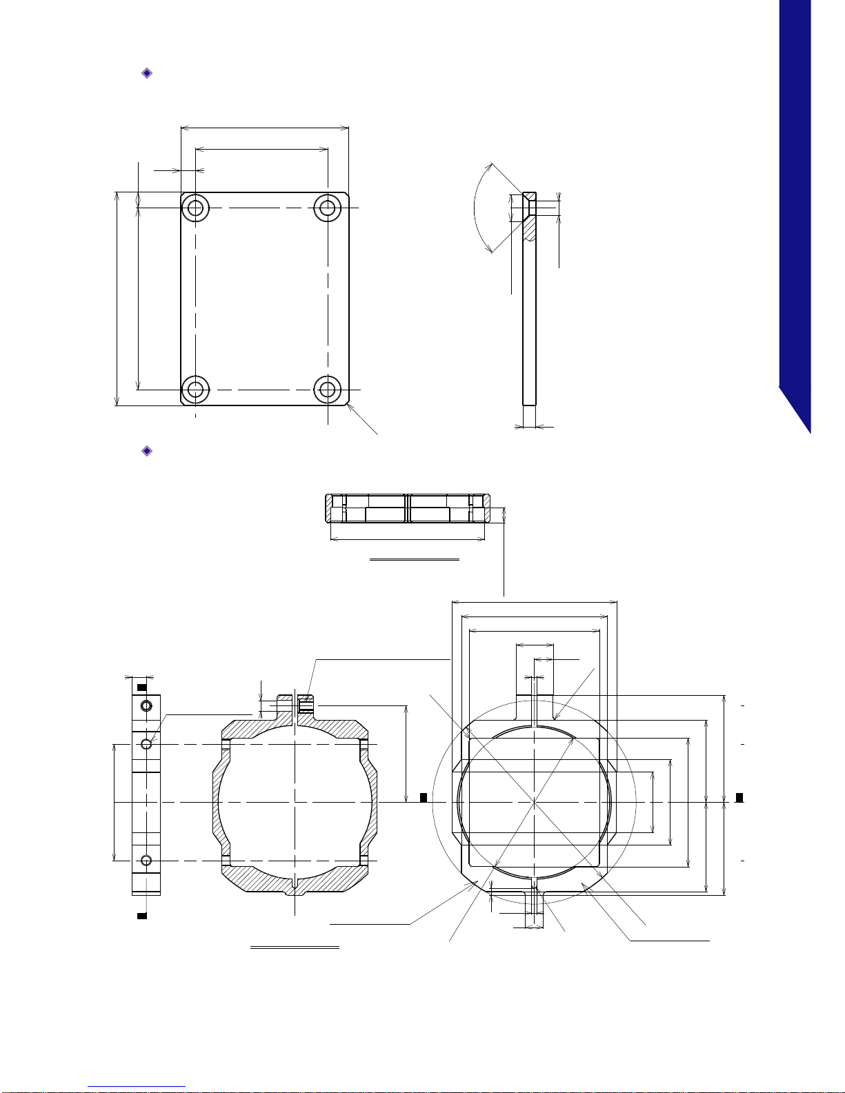
3.2.1. Hi-G Bracket
Hi-G Bracket (Side A)
(mm)
0.8
R
2
1
.
5
25
40
9.5
39.5
42.3
24.6
30
2
-
φ
3
.
4
59.5
55.5
50
2
-
φ
3
.
4
A
A
32
2
R
2
3.2
5.2
7.5
32.5
314.5
4.5 31
2-M3 Depth3 Diameter of drilling4
4-M4 Through tap
2-M3 Depth3 Diameter of drilling4

30
FASTCAM MH6
3.2 Dimensions
Hi-G Bracket (Side B)
(mm)
27.4
53.5
8.5
20.6
27.4
16.5
R
3
0
2
-
(
R
)
3.4
5
2.5
φ
4
.
5
25.3
5.9
4
.
6
(
C
o
n
s
t
a
n
t
)
2-M3 depth6 through tap8.5
Hi-G Bracket (Bottom)
(mm)
7
0.5
SEC.A-A
15.5
21.4
71
76.9
28
4
-
R
1
33
92.4
6.2
18.5
(
R
)
27.06
φ
6
.
6
4
-
φ
3
.
4
20.6
2
-
(
R
)
4
-
C
1
A
A
55.4
R
8
0
2-φ6.5
3.4
6
.
6
(
C
o
n
s
t
a
n
t
)
6.5(2places)
1/4inch helisad 1D
3(4places)
31
FASTCAM MH6
3.2 Dimensions
Hi-G Bracket (Top)
(mm)
4-φ3.4
4-φ6.3
4-90゚
3.5
31
42.5
3.75
3
50
39.5
4
C
1
Hi-G Bracket (Front)
(mm)
φ
5
7
1.5
4
R
1
φ3
1.5
27
SEC.A-A
2
2
(
R
)
36
17
26
30
φ
4
2
.
1
+
0
.
1
0
23
25
8
-
R
1
BB
24
1
6
5
46
40.8
36.4
5.25
10.25
SEC.B-B
φ43
+0.3
0
4
32.5
A
A
4.3 (6places)
2-M3 through tap
M2.6X4.5-SUS303 irisert
Sculpture letters
Inking (white)
Sculpture letters
Inking (white)
32
FASTCAM MH6
3.2 Dimensions
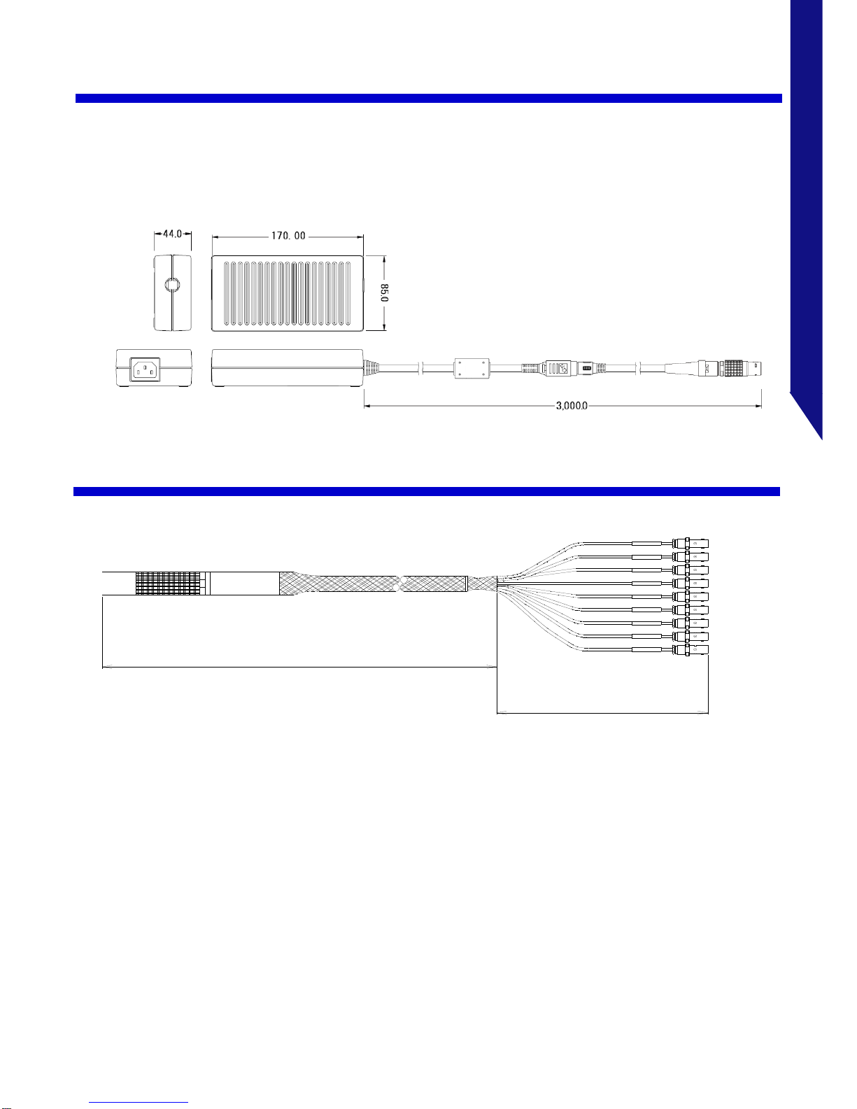
3.2.1. Power Supply Unit
(mm)
3.2.2. I/O 2 PORT Cable
I/O cable
TRIGTTL IN
GENERAL OUT3
GENERAL OUT2
GENERAL OUT1
GENERAL IN
S YN C I N
TRIG TTL OUT
TRIG SW IN
T RI G I N
400
500

4
Contacting Photron

34
FASTCAM MH6
4.1 About the Warranty
About the Warranty
This system has been shipped having undergone rigorous testing. However, in the
unlikely event that it malfunctions due to a manufacturing defect, it will be repaired, at no
charge, within the warranty period.
Warranty Exceptions
The following exceptions will result in fee-based repair, even within the warranty period.
①
Damage or malfunction as a result of fire, earthquake, water damage, lightning, other
natural disasters, pollution, or the effects of abnormal voltage.
②
Damage or malfunction as a result of dropping or mishandling during shipment or when
moving after purchase or misuse.
③
Consumable goods (cables)
④
When repair, adjustment, or alternation done by an entity other than Photron service has
been performed on the system, or damage or malfunction that is determined to be
attributed to a fault in the use the product.
For inquires related to malfunction, contact the dealer where the product was purchased,
or the nearest Photron office.
•
For inquires related to our product, refer to "5.1 Contact Information"36 page.
Reference

5
Contacting Photron
This chapter lists the contact
information to use when contacting
Photron if the system malfunctions or
if a portion of the manual is unclear.

36
FASTCAM MH6
5.1 Contact Information
Contact Information
For inquiries related to FASTCAM MH6, contact Photron at one of the contact points listed
below.
Additionally, the following items will be required for verification when inquiring. You are
kindly asked to prepare them in advance.
Items Verified
Required Information
Contact Information
Company, school or organization name,
customer contact name,
contact phone number,
contact e-mail address.
Product Name
FASTCAM MH6
Serial Number
Shown in the nameplate seal.
Condition of the system, nature of problem, etc.
Contact Information
In Americas and
Antipodes
PHOTRON USA, INC.
9520 Padgett Street, Suite 110, San Diego, CA 92126-4426, USA
Phone: 800-585-2129 or 858-684-3555
Fax: 858-684-3558
E-mail: image@photron.com / www.photron.com
In Europe, Africa
and India
PHOTRON EUROPE LIMITED
The Barn, Bottom Road, West Wycombe, Buckinghamshire
HP14 4BS, U.K.
Phone: +44(0) 1494 48 1011
Fax: +44(0) 1494 48 7011
E-mail: image@photron.com / www.photron.com
In China
PHOTRON (SHANGHAI) LIMITED
Room 20C Zhao-Feng World Trade Building, No. 369 Jiangsu Road Chang
Ning District, Shanghai 200050, China
Phone: 021-5268-3700
Fax: 021-5268-3702
E-mail: info@photron.cn.com / www.photron.cn.com
In other areas
PHOTRON LIMITED
21F, Jimbocho Mitsui Bldg.,
1-105 Kandajimbocho, Chiyoda-Ku, Tokyo 101-0051, Japan
Phone: +81 3 3518 6271
Fax: +81 3 3518 6279
E-mail : image@photron.co.jp / www.photron.co.jp

A
A. Appendix

38
FASTCAM MH6
A.1 Reference Information
A.1. Reference Information
A.1.1. Relative Spectral Response (monochrome)
•
The spectrum response curve is a nominal (a reference) data of the monochrome image
sensor device.
A.1.2. Relative Spectral Response (color)
•
The spectrum response curve is a nominal (a reference) data of the color image sensor
device.

©2018.PH O T R ON L I MITED, Al l right s reser v ed. P r i n ted i n Japa n .
Control No. J181001U
FASTCAM MH6
Hardware Manual Revision 4.00E
Publication Date: November,2018
Publisher: PHOTRON LIMITED
21F, Jimbocho Mitsui Bldg.,
1-105 Kandajimbocho, Chiyoda-Ku, Tokyo 101-0051
 Loading...