


AquaPen-C AP 110-C
AquaPen-P AP 110-P
Manual and User Guide
Please read this manual before operating this product
PSI, spol. s r. o., Drásov 470, 664 24 Drásov, Czech Republic
FAX: +420 511 440 901, TEL: +420 511 440 011, www.psi.cz

© PSI (Photon Systems Instruments), spol. s r. o.
2
© PSI (Photon Systems Instruments), spol. s r. o. (hereinafter PSI), 2018
This document and its parts can be copied or provided to a third party only with the express permission of PSI.
The contents of this manual have been verified to correspond to the specifications of the device. However, deviations cannot
be ruled out. Therefore, a complete correspondence between the manual and the real device cannot be guaranteed. The
information in this manual is regularly checked, and corrections may be made in subsequent versions.
The visualizations shown in this manual are only illustrative.
This manual is an integral part of the purchase and delivery of equipment and its accessories and both Parties must abide
by it.

© PSI (Photon Systems Instruments), spol. s r. o.
3

© PSI (Photon Systems Instruments), spol. s r. o.
4
TABLE OF CONTENTS
1 Information Before Using AquaPen Device .................................................................................................................... 6
2 Technical Specification .................................................................................................................................................... 7
3 General Information ....................................................................................................................................................... 8
3.1 Device Description ................................................................................................................................................. 9
4 List of Equipment and Customer Information .............................................................................................................. 10
5 Care and Maintenance .................................................................................................................................................. 11
6 Principle of Measurement ............................................................................................................................................ 12
7 How to Get Started ....................................................................................................................................................... 15
7.1 Measurements Based on Fluorescence ............................................................................................................... 15
7.1.1 Pulses Description and Setting ........................................................................................................................ 15
7.1.2 Measurement .................................................................................................................................................. 17
7.1.3 OJIP Protocol ................................................................................................................................................... 19
7.1.4 Non-Photochemical Quenching (NPQ) Protocol ............................................................................................. 20
7.1.5 Light Curve (LC) Protocol ................................................................................................................................. 23
7.2 Optical Density Measurement (AquaPen-C only) ................................................................................................ 26
7.2.1 Calibration ....................................................................................................................................................... 26
7.2.2 Measurement .................................................................................................................................................. 26
7.3 Multiple Measurement ....................................................................................................................................... 27
8 Control Menu Tree ........................................................................................................................................................ 28
9 USB Connection ............................................................................................................................................................ 36
10 Bluetooth Connection .............................................................................................................................................. 37
10.1 Bluetooth Pairing ................................................................................................................................................. 37
11 FluorPen Software ................................................................................................................................................... 41
11.1 Software Installation ........................................................................................................................................... 41
11.2 Menu and Icon Explanation ................................................................................................................................. 42
11.2.1 Main Menu ................................................................................................................................................. 42
11.2.2 Menu Settings ............................................................................................................................................. 43
11.2.3 Menu Online Control .................................................................................................................................. 44
11.3 Data Transfer and Visualization ........................................................................................................................... 47

© PSI (Photon Systems Instruments), spol. s r. o.
5
11.4 Firmware Update ................................................................................................................................................. 50
12 GPS Module ............................................................................................................................................................. 52
12.1 GPS / AquaPen Operation ................................................................................................................................... 52
12.2 Data Download .................................................................................................................................................... 53
13 Warranty Terms and Conditions .............................................................................................................................. 54
14 Troubleshooting and Customer Support ................................................................................................................. 55

© PSI (Photon Systems Instruments), spol. s r. o.
6
1 INFORMATION BEFORE USING AQUAPEN DEVICE
Read this manual carefully before operating the device. If you are not sure about anything in the manual, contact the
manufacturer for clarification.
By accepting the device, the customer agrees to follow the instructions in this guide.
Always follow corresponding manuals while working with the AquaPen device or doing the maintenance.
It is forbidden to interfere with the hardware or software of the AquaPen device in any way without previous agreement
with the manufacturer.
The following table presents basic highlight symbols used in this manual:
Symbol
Description
Important information, read carefully.
Complementary and additional information.
Tab. 1 Used symbols.

© PSI (Photon Systems Instruments), spol. s r. o.
7
2 TECHNICAL SPECIFICATION
Measured / Calculated Parameters:
F0, Ft, Fm, Fm‘, QY, NPQ 1, NPQ 2, NPQ 3, OJIP, LC 1, LC 2, LC 3, OD
680*, OD720
*
Saturating Pulse Illumination:
Adjustable from 10 to 100 % (up to 3,000 µmol.m-2.s-1)
Actinic Illumination:
Adjustable from 10 to 1,000 µmol.m-2.s-1
Measuring Illumination:
Adjustable from 0 to 100 % (up to 0.09 µmol.m-2.s-1 per pulse)
LED Emitter specification:
Blue (455 nm) and red-orange (630 nm)
Detector Wavelength Range:
PIN photodiode with 667 to 750 nm bandpass filters
PC Communication modules:
Bluetooth and USB
FluorPen Software:
Windows 7 or higher compatible**
Memory Capacity:
Up to 16 Mb
Internal Data Logging:
Up to 149,000 data points
Display:
Graphical display
Keypad:
Sealed, 2-key tactile response
Keypad Escape Time:
Turns off after 8 minutes of no use
Power Supply:
Li-Ion rechargeable battery
Battery Life:
48 hours typical with full operation
Low Battery Detection:
Low battery indication displayed
Size:
165 mm x 65 mm x 55 mm
Weight:
290 g
Sample Holder:
4 ml cuvette (AquaPen-C AP 110-C)
Submersible optical probe (AquaPen-P AP 110-P)
Operating Conditions:
Temperature: 0 to +55 ºC, 32 to 130 ºF; Relative humidity: 0 to 95 % (non-condensing)
Storage Conditions:
Temperature: -10 to +60 ºC, 14 to 140 ºF; Relative humidity: 0 to 95 % (non-condensing)
Warranty:
1 year parts and labor (see the last page of this Operation Manual for precise warranty conditions)
* Only in AquaPen-C AP 110-C.
** Windows is a registered trademark of Microsoft Corporation.

© PSI (Photon Systems Instruments), spol. s r. o.
8
3 GENERAL INFORMATION
AquaPen is a lightweight, hand-held fluorometer intended for quick and reliable measurements of photosynthetic activity
in algal, cyanobacterial or eventually plant cell suspensions. The photosynthetic activity is derived from the chlorophyll
fluorescence (ChlF) kinetics. ChlF is determined based on a Pulse Amplitude Modulated technique (PAM). For user comfort,
all illumination protocols are predefined and AP offers a set of illumination protocols (more in chapter 7.1) to determined
fast fluorescence kinetics known as OJIP-test as well as slow ChlF kinetics such as quenching analysis or Light response
curve.
AquaPen is equipped with blue and red LED emitters, optically filtered and precisely focused to deliver PAR values of up to
3,000 μmol.m-2.s-1 to measured volume. Blue excitation light (455 nm) is intended for excitation of chlorophylls and thus
for measurements of algal cultures and plant cell suspensions. Red-orange excitation light (630 nm) is suitable for
measurements of cyanobacteria which tend to absorb inefficiently the blue light.
AquaPen is available in two versions: AquaPen-C AP 110-C and AquaPen-P AP 110-P.
AquaPen-P AP 110-P is a probe version of AquaPen, which allows detection of chlorophyll fluorescence in liquid samples
by directly submersing the probe in the suspension medium. It is designed for laboratory measurement and also for field
studies, when it’s necessary to measure in natural conditions. This AquaPen version is supplied with single blue LED emitter
(optionally red or white).
AquaPen-C AP 110-C is a cuvette version of the fluorometer. The sample is measured in a plastic cuvette inserted into a
AP optical head and covered by a top lid. This version is suitable as a hand-held laboratory fluoro-turbidimeter. It can be
also used in field studies, in case it’s possible to sample. Thus, AP 110-C contains an inbuilt turbidimeter for measurements
of optical densities in addition to chlorophyll fluorescence. Due to ultra- high sensitivity of this version – up to 0.5 μg Chl/l
– the AquaPen-C can measure natural water samples containing very low concentrations of phytoplankton.
AP can be operated as a stand-alone instrument and thus is ideal for field studies. Measured data are sequentially stored
in the internal AquaPen memory. Data transfer is via USB or Bluetooth communication. Comprehensive FluorPen 1.1
software provides data transfer routines and many additional features for data presentation in tables and graphs.
AP 110-P is not able to measure Optical density.

© PSI (Photon Systems Instruments), spol. s r. o.
9
3.1 DEVICE DESCRIPTION
Fig. 1 Device description.

© PSI (Photon Systems Instruments), spol. s r. o.
10
4 LIST OF EQUIPMENT AND CUSTOMER INFORMATION
Standard version of the AquaPen device package consists:
• AquaPen-C AP 110-C or AquaPen-P AP 110-P
• Carrying Case
• 4 ml volume plastic cuvette with stopper (AquaPen-C only)
• FluorPen software and driver (on a USB flash disc)
• Operation Manual (PDF on a USB flash disc)
• USB Cable
• Other Accessories or Optional Features (according to your specific order)
For USB connection you need to have the USB driver installed in your PC. You find the driver on the
installation disk (USB driver folder).
If any item is missing, please, contact the manufacturer. Also check the carton for any visible external
damage. If you find any damage, notify the carrier and the manufacturer immediately. The carton and
all packing materials should be retained for inspection by the carrier or insurer.
For customer support, please write to: support@psi.cz

© PSI (Photon Systems Instruments), spol. s r. o.
11
5 CARE AND MAINTENANCE
AquaPen-P AP 110-P
• Never submerge the whole device in the measured sample!
• Keep in mind that only the optical tip can be submerged!
• Rinse the optical tip of the AquaPen-P in freshwater after each use.
• Inspect visually the optical window after each deployment. If cleaning is needed, use the soapy water and
soft, non-abrasive tissue for cleaning the optical part.
• The device should not come in contact with any organic solvents, strong acids or bases.
AquaPen-C AP 110-C
• Never submerge the device in water!
• To measure samples, use a standard 4 ml volume cuvette. Fill the cuvette almost full, i.e., about 3 ml of the
volume.
• Keep the optical part clean and dry. If cleaning is needed, use soft, non-abrasive tissue.
• The device should not come in contact with any organic solvents, strong acids or bases.

© PSI (Photon Systems Instruments), spol. s r. o.
12
6 PRINCIPLE OF MEASUREMENT
AquaPen is a new version of the FluorPen fluorometer which can measure different parameters in solutions of algae,
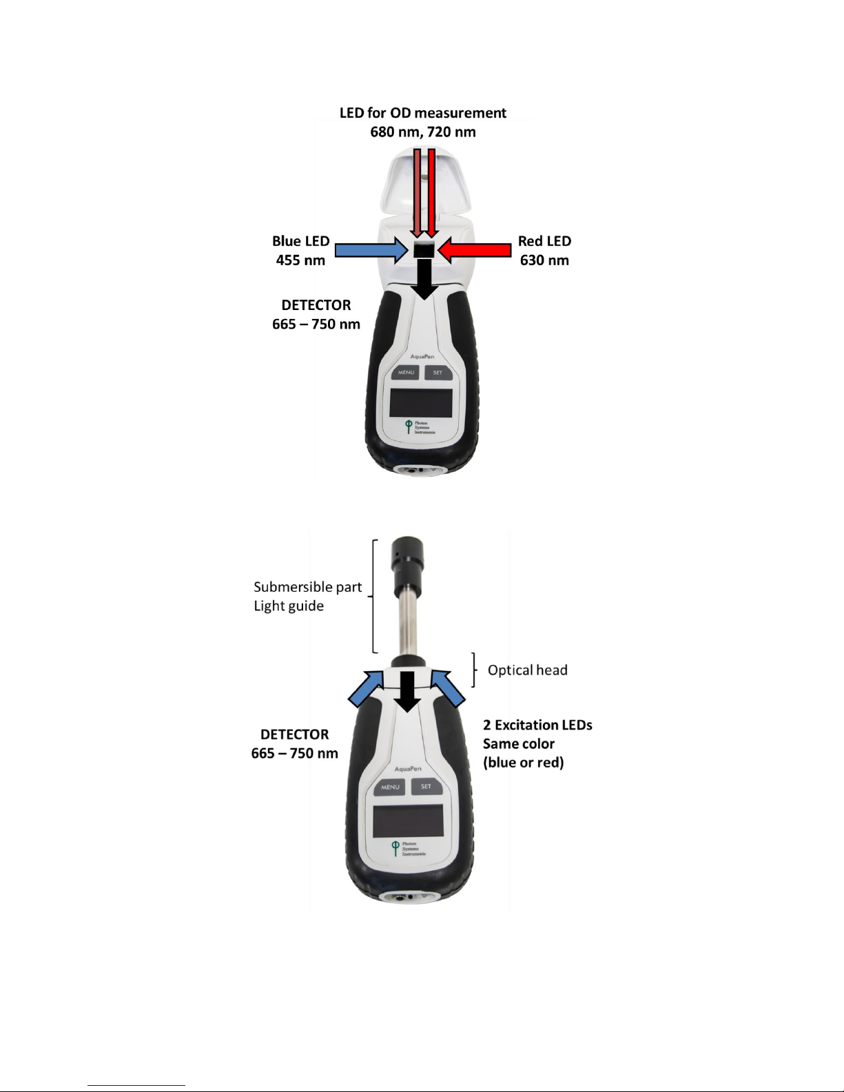
cyanobacteria and plant cell suspensions at very low concentrations. It is equipped with a blue and red LED emitter (Fig.
3, Fig. 4), optically filtered and precisely focused to deliver light intensities of up to 3,000 µmol.m-2.s-1 to measured
suspensions. Blue excitation light (455 nm) is intended for chlorophyll excitation, i.e., for measuring chlorophyll
fluorescence in algal cultures and plant cell suspensions. Red-orange excitation light (630 nm) is intended for excitation
through phycobilins and is suitable for measuring in cyanobacterial cultures. Due to high sensitivity - 0.5 µg Chl/l - the
AquaPen can measure natural water samples containing low concentrations of phytoplankton.
Parameters recorded by the AquaPen include Ft, QY, NPQ, OJIP Analysis, Light Curve, and also optical density at 680 and
720 nm (only AP 110-C).
To use measurements of chlorophyll fluorescence to analyze photosynthesis, researchers must distinguish between
photochemical quenching and non-photochemical quenching (heat dissipation). This is achieved by stopping
photochemistry, which allows researchers to measure fluorescence in the presence of non-photochemical quenching
alone. To reduce photochemical quenching to negligible levels, a high intensity, short flash of light is applied to the leaf.
This transiently closes all PSII reaction centers, which prevents energy of PSII being passed to downstream electron carriers.
Non-photochemical quenching will not be affected if the flash is short. During the flash, the fluorescence reaches the level
reached in the absence of any photochemical quenching, known as maximum fluorescence Fm. The efficiency of
photochemical quenching (which is a proxy of the efficiency of PSII) can be estimated by comparing Fm to the steady yield
of fluorescence in the light Ft and the yield of fluorescence in the absence of photosynthetic light F0. The efficiency of
non-photochemical quenching is altered by various internal and external factors. Alterations in heat dissipation mean
changes in Fm. Heat dissipation cannot be totally stopped, so the yield of chlorophyll fluorescence in the absence of nonphotochemical quenching cannot be measured. See picture below
Fig. 2.
Fig. 2 Chlorophyll fluorescence.

© PSI (Photon Systems Instruments), spol. s r. o.
13
Measuring the optical density of growing cultures is a common method to quantify various important culture parameters
like cell concentration, biomass production or changes in the cell morphology. Continuous measuring of optical density is
the most basic and powerful tool for providing optimal yields.
AquaPen measures:
FT - Instantaneous Chlorophyll Fluorescence
Ft is equivalent to F0 if the sample is dark-adapted.
QY - Quantum Yield
QY is a measure of the Photosystem II efficiency. QY is equivalent to Fv/Fm in dark-adapted samples and to F
v '
/F
m '
in
light-adapted samples.
OJIP - Chlorophyll Fluorescence Induction Kinetics
The OJIP curves enable observing major changes that occur during exposure of a sample to high irradiance (see more in
Chapter 0).
NPQ - Non-Photochemical Quenching
The NPQ protocol is the most typically used measuring approach to quantify photochemical and non-photochemical
quenching. The measurement should be performed with a dark-adapted sample. More in chapter 7.1.4.
LC - Light Curve
Photosystem II Quantum Yield estimated from fluorescence that is measured sequentially in several different light
levels. More in chapter 7.1.5.
OD - Optical Density* at 680 nm and 720 nm.
Optical density at 680 nm represents light scattering and chlorophyll absorption. Optical density at 720 nm represents
light scattering-corresponds to cell density. More in chapter 7.2.
*Optical density is defined as
OD = -Log(I/Io) - where "Io" is the irradiance that is transmitted through the cuvette filled with medium without algae or
cyanobacteria. This quantity must be measured as the reference. "I" is the irradiance transmitted through the cuvette with
algal or cyanobacterial suspension in which the OD is measured. "Log" is the decadic logarithm of the I/Io ratio. Thus, the
optical density OD=1 means that the light at the respective wavelength is attenuated by the algae or cyanobacteria 10
times relative to the reference. With OD=2, the attenuation relative to the reference is 100 times.
© PSI (Photon Systems Instruments), spol. s r. o.
14
Fig. 3 AquaPen-C AP 110-C.
Fig. 4 AquaPen-P 110-P.

© PSI (Photon Systems Instruments), spol. s r. o.
15
7 HOW TO GET STARTED
For more detailed information on particular steps of AquaPen operation please refer to chapter 8.
The device works on Li-Ion battery or is charged via USB cable from PC or grid.
The AquaPen is controlled using two buttons:
• Use the MENU key to scroll through sequential menu options on the digital display.
• Use the SET key to select a menu option based on cursor (>) position.
7.1 MEASUREMENTS BASED ON FLUORESCENCE
7.1.1 PULSES DESCRIPTION AND SETTING
Flash pulse
This function serves for setting of measuring pulses intensity. The measuring pulses are weak pulses, which are able to
induce the minimal chlorophyll fluorescence (F0 or Ft). It takes only 30 µs and the maximum intensity is
3,000 µmol.m-2.s-1. It means 30 µs * 3,000 µmol.m-2.s-1 = 0.09 µmol.m-2 per pulse is the maximal intensity of the flash pulse.
Super pulse
This function serves for setting intensity of the saturating pulse. Saturating pulse is able to induce maximum chlorophyll
fluorescence (Fm). 100 % of intensity equals approximately 3,000 µmol.m-2.s-1.
Actinic pulse
This function serves for setting intensity of measuring pulses. Actinic light is basically the ambient light in which the algae
are growing. 100 % of intensity equals approximately 1,000 µmol.m-2.s-1.
Pulses used in predefined protocols:
Measurements based on fluorescence
Used pulses
Ft
Flash pulse
QY
Flash pulse, Super pulse
OJIP
Super pulse
NPQ protocols
Flash pulse, Super pulse, Actinic pulse
Light Curves
Flash pulse, Super pulse (Actinic pulse is preset)
Default setting of light color and intensities:
Measuring color 455nm
Flash pulse 30 % = Measuring flash pulse
Super pulse 70 % = Saturating pulse
Actinic pulse 300 µmol.m-2.s-1 (30 %) = Actinic light
Please note that those paramets are recommended by manufacturer and you can change them according to your needs.

© PSI (Photon Systems Instruments), spol. s r. o.
16
Setting of optimal intensities of pulses:
Flash pulse setting
The optimum value of Flash pulse you can identify with QY measurement. Before QY measurement is recommended to set
the pulse color according to measured culture and intensity of Super pulse on 70 %.
Please note that QY measurement should be performed with dark adapted culture. If you use cuvette version of AquaPen,
“new” 4 ml of culture is needed for every measurement (culture can be inhibited after measurement).
F0 is increasing linearly with growing Flash pulse. Increasing Flash pulse is not affecting background value.
The Flash pulse setting recommended by manufacturer is 30 %. You can increase the intensity of Flash pulse in case of
culture with very low density. Please note that high intensities of Flash pulse can cause undesirable “actinic effect”. In this
case the Flash pulse initiates the photochemistry and affects F0 and the QY value will be lower.
The Flash pulse intensity at which the highest value of QY is reached is optimal for your culture (Fig. 5).
Fig. 5 QY measurement performed with different intensities of Flash pulse. Optimal setting is highlighted in red rectangle.
Super pulse setting
Best way to recognized the optimal intensity of Super pulse is perform OJIP measurement.
Please note that OJIP measurement should be performed with dark adapted culture. If you use cuvette version of AquaPen,
“new” 4 ml of culture is needed for every measurement (culture can be inhibited after measurement).
The Super pulse setting recommended by manufacturer is 70 %.
Perform the OJIP measurement with different intensities of Super pulse. When the value of Fv/Fm stops growing during the
measurement with various Super pulse intensities, the Super pulse intensity is optimal for your culture (Fig. 6).

© PSI (Photon Systems Instruments), spol. s r. o.
17
Fig. 6 OJIP measurement performed with different intensities of Super pulse.
Actinic pulse setting
Intensity of Actinic pulse should correspond with cultivation light intensity or should be set according to application.
If you see Overflow on display during measurement there is two options how to get required result.
You can dilute your sample or lower the intensity of pulse.
In case of Low value on display during measurement you can concentrate your sample or heighten
the intensity of pulse.
7.1.2 MEASUREMENT
No device calibration is needed before chlorophyll fluorescence measurement. Results of fluorescence measurement
depend on device settings.
Fluorescence measurement with AquaPen-C perform as follows:
• Fill the cuvette with the sample of algae or cyanobacteria and close the cuvette with the stopper. Minimal
volume of sample is 3 ml.
• Put cuvette with sample to AquaPen device and close the cover.
• If you want to prepare dark adapted sample (prior for F0, QY, NPQ, LC) please wait for defined period of
time. Duration of sufficient dark-adaptation depends on species, mostly varies between 5 and 15 minutes.
• Then mix up the sample in AquaPen (hold the cap and turn over a few times). You have to mix up the sample
after dark adaptation because of a risk of seating on the bottom of the cuvette. Sample could be wrong
measured.
• Turn ON device – hold SET button for 1 sec.
• Go to Measure > choose required parameter for example - Ft.
• Press SET to confirm.

© PSI (Photon Systems Instruments), spol. s r. o.
18
• AquaPen measure required parameter. If you choose protocol such as OJIP, LC or NPQ the display shows the
percentage of measurements.
• Value of required parameter appears on display after measuring. Result of OJIP, NPQ or LC protocol is a
graph, so all data you will see after data download using FluorPen Software. (page 47).
• During the measurement all data are stored into the device memory.
Fluorescence measurement with AquaPen-P perform as follows:
• If you want to prepare dark adapted sample (prior for Ft, QY, NPQ, LC) place the sample for defined period
on dark place. Duration of sufficient dark-adaptation depends on species, mostly varies between 5 and 15
minutes.
• Turn ON device – hold SET button for 1 sec.
• Go to Measure > choose required parameter for example - Ft.
• Submerge the probe into the sample.
• Press SET to confirm.
• AquaPen measures required parameter. If you choose protocol such as OJIP, LC or NPQ the display shows the
percentage of measurements.
• Value of required parameter appears on display after measuring. Result of OJIP, NPQ or LC protocol is a
graph, so all data you will see after data download using FluorPen Software. (page 47).
• During the measurement all data are stored into the device memory.

© PSI (Photon Systems Instruments), spol. s r. o.
19
7.1.3 OJIP PROTOCOL
The AquaPen device offers the possibility to capture rapid fluorescence transient – OJIP, which occurs during exposure of
photosynthesizing organisms to high irradiance. The FluorPen software enables data downloading to a personal computer
and subsequent OJIP analysis.
The OJIP protocol includes the following extracted and technical parameters:
Abbreviation
Explanation
Bckg
Background
F0
F0 = F
50µs
, fluorescence intensity at 50 µs
Fj
Fj = fluorescence intensity at J-step (at 2 ms)
Fi
Fi = fluorescence intensity at i-step (at 30 ms)
Fm
Fm = maximal fluorescence intensity
Fv
Fv = Fm - F0 (maximal variable fluorescence)
Vj
Vj = ( Fj - F0 ) / ( Fm - F0 )
Vi
Vi = ( Fi - F0 ) / ( Fm - F0 )
Fm / F0
FV / F0
Fv / Fm
M0 or (dV/dt)0
M0 = TR0 / RC - ET0 / RC = 4 ( F
300
- F0 ) / ( Fm - F0 )
Area
Area between fluorescence curve and Fm (background subtracted)
Fix Area
Area below the fluorescence curve between F
40µs
and F
1s
(background subtracted)
SM
SM = Area / ( Fm - F0 ) (multiple turn-over)
SS
SS = the smallest SM turn-over (single turn-over)
N
N = SM . M0 . ( 1 / VJ ) turn-over number QA
Phi_P0
Phi_P0 = 1 – ( F0 / Fm ) (or Fv / Fm)
Psi_0
Psi_0 = 1 - VJ
Phi_E0
Phi_E0 = ( 1 – ( F0 / F
M
)) . Psi_0
Phi_D0
Phi_D0 = 1 – Phi_P0 – ( F0 / Fm )
Phi_Pav
Phi_Pav = Phi_P0 ( SM / tFm ) t
Fm
= time to reach Fm (in ms)
ABS / RC
ABS / RC = M0 . ( 1 / VJ ) . (1 / Phi_P0 )
TR0 / RC
TR0 / RC = M0 . ( 1 / VJ )
ET0 / RC
ET0 / RC = M0 . ( 1 / VJ ) . Psi_0
DI0 / RC
DI0 / RC = ( ABS / RC ) – ( TR0 / RC )
Formulas Derived From:
R.J. Strasser, A. Srivastava and M. Tsimilli-Michael (2000): The fluorescence transient as a tool to characterize and screen
photosynthetic samples. In: Probing Photosynthesis: Mechanism, Regulation and Adaptation (M. Yunus, U. Pathre and P.
Mohanty, eds.), Taylor and Francis, UK, Chapter 25, pp 445-483.

© PSI (Photon Systems Instruments), spol. s r. o.
20
7.1.4 NON-PHOTOCHEMICAL QUENCHING (NPQ) PROTOCOL
The NPQ protocol is the most typically used measuring approach to quantify photochemical and non-photochemical
quenching. The measurement should be performed with a dark-adapted sample. Thereby, it may not be appropriate under
field conditions.
The NPQ protocol starts by giving a measuring light to acquire minimal level of fluorescence F0. A short saturating flash of
light is then applied to reduce the plastoquinone pool and measure maximum fluorescence in the dark-adapted state, Fm.
After a short dark relaxation, the sample is exposed to actinic irradiance for tens to hundreds of seconds to elicit a transient
of the Kautsky effect. Moreover, a sequence of saturating flashes is applied on top of the actinic light to probe the nonphotochemical quenching NPQ and effective quantum yield of photosynthesis QY in light adapted state. After exposure to
continuous illumination, the relaxation of non-photochemical quenching is determined by means of saturating pulses
applied in dark (Fig. 7).
Three NPQ protocols, NPQ1, NPQ2 and NPQ3 are predefined. The protocols differ in the duration of the light exposure and
the dark recovery phase, in the number and interval between pulses. See Tab. 2:
Phase
Duration
# of pulses
1st pulse
Pulse interval
NPQ1
Light
60 s 5 7 s
12 s
Dark recovery
88 s 3 11 s
26 s
NPQ2
Light
200 s
10
10 s
20 s
Dark recovery
390 s 7 20 s
60 s
NPQ3
Light
200 s
10
11 s
21 s
Dark recovery
60 s 2 20 s
21 s
Tab. 2 NPQ Protocols.
The protocol includes following measured and calculated parameters:
Abbreviation
Explanation
F
0
minimum fluorescence in dark-adapted state
F
m
maximum fluorescence in dark-adapted state, measured during the first
saturation flash after dark adaptation
F
p
fluorescence in the peak of fast Kautsky induction
Fm_L, Lss, D, Dss
1
maximum fluorescence
QYmax
2
maximum quantum yield of PSII in dark-adapted state - Fv/F
m
QY_L, Lss, D, Dss
1,3
effective quantum yield of PSII
NPQ_L, Lss, D, Dss
1,4
non-photochemical chlorophyll fluorescence quenching
Qp_L, Lss, D, Dss
1,5
coefficient of photochemical quenching, an estimate of open PSII reaction centers

© PSI (Photon Systems Instruments), spol. s r. o.
21
1
L - indicates light adapted parameters; D - refers to dark recovery phase after switching of the actinic illumination; n -
represents a sequential number of light phase; ss - steady state
2
Calculated as (Fm – F0) / Fm
3
Calculated as (Fm_Ln – Ft_Ln) / Fm_Ln or of corresponding steady state or dark recovery parameters
4
Calculated as (Fm – Fm_Ln) / Fm_Ln or of corresponding ss, Dn or Dss parameters
5
Calculated as (Fm_Ln – Ft_Ln) / (Fm_Ln – F0_Ln) or of corresponding ss, Dn or Dss parameters
F0_Ln is calculated as F0 / ((Fm – F0) / Fm + F0 / Fm_Ln).
For more details please refer to: Oxborough K., Baker N.R. (1997): Resolving chlorophyll a fluorescence images of
photosynthetic efficiency into photochemical and non-photochemical components: calculation of qP and Fv’/Fm’ without
measuring F0’. Photosynthesis Research 54: 135-142.

© PSI (Photon Systems Instruments), spol. s r. o.
22
Fig. 7 NPQ Protocol.

© PSI (Photon Systems Instruments), spol. s r. o.
23
7.1.5 LIGHT CURVE (LC) PROTOCOL
The protocol called Light Curve (LC) was designed to acquire parameters for construction of Light Response Curve relating
the rate of photosynthesis to photon flux density. The method is based on successive measurements of the sample exposed
to a stepwise increase of light intensity. The effective quantum yields of photosynthesis are determined under various light
intensities of continuous illumination. Measurement is based on pulse modulated fluorometry (PAM).
Several LC protocols are predefined in AP. These differ in number and duration of individual light phases and light
intensities.
# of phases
Phase duration
Light intensities [µmol.m-2.s-1]
LC1 6 60s
10; 20; 50; 100; 300; 500
LC2 5 30s
100; 200; 300; 500; 1000
LC3 7 60s
10; 20; 50; 100; 300; 500; 1000
Tab. 3 LC Protocols.
The protocol includes following measured and calculated parameters:
Abbreviation
Explanation
F
0
minimum fluorescence in dark-adapted state
F
m
maximum fluorescence in dark-adapted state
Fm_Ln
‡
maximum fluorescence in light adaptation state
Ft_Ln
‡
instantaneous fluorescence during light adaptation
QYmax*
maximum quantum yield of PSII in dark-adapted state - Fv/Fm
QY_Ln‡**
instantaneous PSII quantum yield induced in light
‡
n represents a sequential number of light phase
*Calculated as (Fm – F0) / Fm
** Calculated as (Fm_Lx – Ft_Lx) / Fm_Lx

© PSI (Photon Systems Instruments), spol. s r. o.
24
Fig. 8 LC1 Protocol.

© PSI (Photon Systems Instruments), spol. s r. o.
25
Fig. 9 LC2 Protocol.

© PSI (Photon Systems Instruments), spol. s r. o.
26
7.2 OPTICAL DENSITY MEASUREMENT (AQUAPEN-C ONLY )
7.2.1 CALIBRATION
Blank – either water or ideally medium used to cultivate the culture you plan to measure in AquaPen. Calibration assures
you that your measurements are accurate within the specification limits that led you to select the instrument in the first
place. It is better to calibrate your device before every set of samples.
It is necessary to calibrate AquaPen after every switch ON.
Prior OD measurement perform the calibration as follows:
• Use the standard 4 ml cuvette.
• Clean the cuvette with distilled water and paper tissue.
• As a calibration standard use cultivation medium (BBM, BG11 etc.) or distilled water.
• Put cuvette with medium (minimal volume 2 ml) into the AquaPen device.
• Turn ON device – hold SET button for 1 sec.
• Go to Measurement > OD > Calibration.
• Press SET button to confirm the calibration.
• For checking if the calibration went well go to Measurement > OD > OD680nm (or OD720nm).
• Press SET to confirm the measurement.
• On display should appear value 0.000.
• If the OD value is higher than 0.000 repeat OD calibration again.
• Remember that the calibration is done for the particular cuvette. If you want to use another cuvette, you
should make the calibration with this one.
• Calibration is automatically stored into the device memory and is save till the device turn OFF.
Please remember or mark the orientation of the cuvette in the device. For repeated measurements it
is recommended to position the cuvette always in the same orientation in the AP cuvette holder.
7.2.2 MEASUREMENT
• Fill the cuvette with a sample of algae or cyanobacteria and close the cuvette with the stopper. Minimal
volume of sample is 2 ml.
• Put cuvette with sample to AquaPen device.
• Close the cover.

© PSI (Photon Systems Instruments), spol. s r. o.
27
• Go to Measurement > OD680nm or OD720nm.
• Press SET to confirm.
• Value of required parameter appears on display after measuring. Measured data are stored into the device
memory and can be downloaded to PC (page 47).
7.3 MULTIPLE MEASUREMENT
Except single measurement you can perform multiple measurements.
In this mode AquaPen repeats measurements according to parameters, which you have set in Settings > Multi (see Menu
tree, page 28)
Multi type – choose your required parameter - Ft, QY, OD....
Multi interval – set the time interval between measurements
Multi repeats – set the number of repeated measurements
Use averaging – serves to confirm Repeat and Interval Options for each measurement within Multi Option – select YES or
NO.
• Prepare the sample like for single measurement.
• Go to Measurement > Multi.
• Press SET to confirm.
• Values appears on display after each repeat of measurement and are automatically stored to the device
memory. If you used protocol (OJIP, NPQ, LC) all data you will see after download data (page 47).
Modes of Multiple measurement:
1. AquaPen is connected via USB to computer
The device measures predefined number of repeats and does not swicht off between measurements. Progress of the
measurement is displayed in percentage.
2. AquaPen is not connected to the computer
The device measures continuously according to predefined protocol and interval. The multiple measurement is
interrupted only by manual switching on of the device. The device turns off between measurements.

© PSI (Photon Systems Instruments), spol. s r. o.
28
8 CONTROL MENU TREE
The next pages show the structure of the operation scheme, which includes the Main Menu, first-level Sub-Menus and
second-level Sub-Menus.
• The blue color represents the Main Menu and its Options.
• The yellow color represents the first-level Sub-Menus and their Options.
• The green color represents the second-level Sub-Menus and their Options.
• Full-line arrows are used for the SET key.
• Dashed-line arrows are used for the MENU key.

© PSI (Photon Systems Instruments), spol. s r. o.
29

© PSI (Photon Systems Instruments), spol. s r. o.
30

© PSI (Photon Systems Instruments), spol. s r. o.
31

© PSI (Photon Systems Instruments), spol. s r. o.
32

© PSI (Photon Systems Instruments), spol. s r. o.
33

© PSI (Photon Systems Instruments), spol. s r. o.
34

© PSI (Photon Systems Instruments), spol. s r. o.
35

© PSI (Photon Systems Instruments), spol. s r. o.
36
9 USB CONNECTION
Connect the USB cable with the AquaPen device. Please note that lock in system is used.
Pay attention when connecting the USB cable not to damage the outlet connector on the Pen
device. Make sure that you orient the cable correctly prior connecting the inlet with the outlet and
the cable is upright towards the device.
To connect AquaPen with your computer please follow steps below in Fig. 10:
Fig. 10 How to connect AquaPen with PC.
A) Outlet connector on AquaPen device. B) Inlet part on the USB cable. C – E) Position the cable horizontally, plug in the
inlet and screw the securing screw. F) Correct connection of the USB cable and Pen device.
Connect the USB cable to a computer. The AquaPen switches ON automatically after connecting the cable to the PC. For
USB connection you need to have the USB driver installed in your PC. You find the driver on the installation disk (USB driver
folder). If you check the Device Manager in Windows you should see the USB serial port in the device tree. In case of
missing driver, you may download it from PSI websites. When the driver is installed correctly you should be able to connect
to the device in the FluorPen software menu Setup > Device ID.
For more information about FluorPen software see chapter 11.

© PSI (Photon Systems Instruments), spol. s r. o.
37
10 BLUETOOTH CONNECTION
Before you set up the Bluetooth connection between the AquaPen and your PC, make sure you have these components:
1. Bluetooth enabled PC
The PC with which you connect must have Bluetooth wireless technology, either built-in or through a Bluetooth card. Make
sure that the PC's Bluetooth setting is "discoverable" (meaning that it shows up when other devices search for nearby
Bluetooth connections). Consult the user guide for your PC or Bluetooth card to learn how to do this.
2. Bluetooth configuration software properly set up on PC
Before you can download files to your PC, you will need to set up the Bluetooth software that came with your PC, or your
PC's Bluetooth card. This software varies by manufacturer. Please consult your PC's Bluetooth documentation for more
information.
3. Bluetooth must be switched on visible on both devices
To pair the AquaPen with another Bluetooth device, such as a computer, you will need to ensure that Bluetooth is switched
on visible on both devices.
10.1 BLUETOOTH PAIRING
1. Enabling Bluetooth in the AquaPen
• Switch ON the AquaPen (press and hold the SET key).
• Scroll to the Accessories menu (press the MENU key, then press the SET key).
• Select Bluetooth On (press the MENU key, then press the SET key) to enable Bluetooth.
Keep in mind that the AquaPen turns off automatically after about 8 minutes of no action.
Turning off the AquaPen always turns off Bluetooth.
2. Starting Bluetooth Application on Your PC
Be aware that this description is working on Windows 7; some of the steps may be different on your PC.
• Select: Start > Devices and Printers (Fig. 11).
You may also start your Bluetooth application via the Control Panel: Start > Control Panel >
Hardware and Sound > Devices and Printers.

© PSI (Photon Systems Instruments), spol. s r. o.
38
Fig. 11 Start Bluetooth Application.
3. Opening the Add Bluetooth Device Application
• Select: “Add a device” to start searching new Bluetooth device. Be sure that the AquaPen is in discoverable
mode (see step 1).
Fig. 12 Add a device.
4. Selecting the AquaPen
• Select: PSI AquaPen icon.
• Select: Next (Fig. 13).
Fig. 13 Select the AquaPen.

© PSI (Photon Systems Instruments), spol. s r. o.
39
5. Starting the Pairing Process
This step is different for old and new version of Bluetooth module.
Old version:
Your Bluetooth Pairing Code is: 0000
• Select: “Enter the device’s pairing code”.
• Enter: 0000 (four digits).
• Select: Next (Fig. 14).
Fig. 14 Pairing process.
New version:
• Select: Yes (Fig. 15). Please note that the FluorPen device does not display the verification number. The
verification code is not important for the BT connection.
• Select: Next.
Fig. 15 Verifying of the BT pairing.
6. Completing the AquaPen Pairing
• Select: Close (Fig. 16).

© PSI (Photon Systems Instruments), spol. s r. o.
40
Fig. 16 Finishing.
On computer run the program FluorPen 1.1. For more information about FluorPen software see chapter 11.

© PSI (Photon Systems Instruments), spol. s r. o.
41
11 FLUORPEN SOFTWARE
11.1 SOFTWARE INSTALLATION
1. Save the FluorPen software provided on the USB flash disk to your computer and launch the FluorPen program.
2. To connect and recognize your AquaPen device in the FluorPen software proceeds first with the registration of
your FluorPen software (Fig. 17).
• Select: Help > Register
• Enter: your serial registration number.
• Select: OK
Fig. 17 Software registration.
Please note that you will find your serial (registration) number in the file SN.txt, which is
included on the enclosed USB flash disk.
Please remember: it is not possible to download data from the AquaPen device without
software registration.
3. Switch on the AquaPen and enable Bluetooth or connect USB cable to the PC.
4. Make sure that your PC and the AquaPen are properly paired (see chapter 9 and 10 for complete information on
USB and Bluetooth pairing).
5. Select: Setup > Device ID (Ctrl+I). If properly connected, the message “Device: AquaPen” appears in the bottom
part of the screen (Fig. 18).

© PSI (Photon Systems Instruments), spol. s r. o.
42
Fig. 18 Connecting AquaPen with Software.
11.2 MENU AND ICON EXPLANATION
11.2.1 MAIN MENU
MENU: File
Load Loads previously saved data files.
Save Saves data to hard disc.
Export Exports data in .txt format.
Export to JSON Exports data in JavaScript Object Notation.
Close Closes the current experiment.
Close All Closes all running experiments.
Exit Exits the program.
MENU: Device
Download Downloads data from the AquaPen to your PC.
Erase Memory Erases data from the AquaPen memory.
Online Control Online control of AP device.
Attach GPS File Used for download data from GPS module (active
only in AquaPen version AP 100).

© PSI (Photon Systems Instruments), spol. s r. o.
43
MENU: Setup
Device ID Detects the connected device.
Update Firmware Used for firmware updates.
Settings Used for modification of the program
settings.
MENU: Help
About Offers basic information about the program.
Register Used for the FluorPen software registration.
Icon Explanation:
11.2.2 MENU SETTINGS
MENU > Setup > Settings
After Download – Memory Erase
If the box is checked the AquaPen memory is erased after each data
download.
Data – Inverted
If the box is checked the polarity of data is inverted, e.g., multiplied
by -1. This feature can be helpful for a certain type of experiment
when the measured data are undesirably interpreted as negative
values.
Data – Add to opened
If the box is checked the downloaded data are added to that of the
current opened experiment.
Download
Downloads data from the AquaPen to PC.
Load
Loads (opens) previously saved data files.
Save
Saves data to hard disc.
Export
Exports data in .txt format.

© PSI (Photon Systems Instruments), spol. s r. o.
44
Data – GPS Visible
This option is active only in older AquaPen version AP 100. In new version AP 110 the GPS data are automatically
downloaded and paired with protocol measurements.
Graf – Single
If the box is checked all measured data are visualized in one graph, i.e., the value of each new measurement is added to
the currently used graph window.
If the box is not checked a new graph is opened for every new measurement.
11.2.3 MENU ONLINE CONTROL
This function can be used for Online Control your AquaPen device after connection with your PC.
• Select: Menu > Device > Online Control
Online Control – Switches
Sound On/Off - choose On/Off for device beeping.
Measuring color – choose 455nm or 630nm for measuring fluorescence protocols. This function is active only in the
AquaPen-C 110-C model.
Multi use averaging (YES/NO) – serves to confirm Repeat (number of repetitions) and Interval (time between
measurements) Options for each measurement within Multi Option – select YES or NO.
Online Control – Values
You can change settings of Actinic, Super or Flash Pulse light. You can also set Averaging of Ft, OJIP, NPQ, LC measurements.
You can set time between measurements (Interval) and also you can set number of Multiprotocol measurements (1-1000),
type of Multiprotocol or time between measurements.

© PSI (Photon Systems Instruments), spol. s r. o.
45
Online Control – Time
Set the AquaPen time a date. You can also synchronize time of AquaPen device with computer time.
Online Control – Protocols
Choose the protocol for measuring. AquaPen device start to measure. After measuring you can download data.
Measuring of OD 680nm and OD 720nm is active only in the AquaPen-C 110-C model.

© PSI (Photon Systems Instruments), spol. s r. o.
46

© PSI (Photon Systems Instruments), spol. s r. o.
47
11.3 DATA TRA NSFER AND VISUALIZAT ION
1. Perform a measurement with your AquaPen. In Fig. 19 we did an OJIP measurement.
2. Click the Download icon or select Device > Download.
3. The Data table appears.
Fig. 19 Example of Data Transfer and Visualization.

© PSI (Photon Systems Instruments), spol. s r. o.
48
4. To visualize measurement in the graphic mode, click the Graph field in the bottom bar.
5. The colored Graph of measured data appears (Fig. 20).
Fig. 20 Graphic visualization of experiment.
6. For export press File > Export or Export icon, select what you want to export (Ft, QY, OJIP…) - Fig. 21.
Selected only – exports only one measurement that is selected by mouse, otherwise it will export everything.
Source data – exports raw data, in case of OJIP: points of the curve.
Description – exports the data description if any.
Computed values – export calculated data, in case of OJIP: F0, Fi, Fj...

© PSI (Photon Systems Instruments), spol. s r. o.
49
Fig. 21 Export data.

© PSI (Photon Systems Instruments), spol. s r. o.
50
11.4 FI RMWARE UPDATE
All data in the AquaPen memory are erased during the firmware update!
Before starting any firmware update, export all your data from the AquaPen memory into your
computer!
1. Starting Update
• Select: Setup > Update Firmware From File (Fig. 22).
Fig. 22 Update Firmware.
2. Warning
• Select: OK to start update (Fig. 23)
Fig. 23 Warning.
3. Selecting .bxn file
• Find: Binary file (with the extension .bxn) (Fig. 24).
• Select: Open.

© PSI (Photon Systems Instruments), spol. s r. o.
51
Fig. 24 Select .bxn file.
4. Finishing Upload
• Select: OK to start uploading of the update (Fig. 25).
Fig. 25 Data loss warning.
• The bottom bar indicates the upload progress (Fig. 26).
Fig. 26 Upload progress.
• Press: OK to finish upload (Fig. 27).
Fig. 27 Finish upload.

© PSI (Photon Systems Instruments), spol. s r. o.
52
12 GPS MODULE
AquaPen device has integrated GPS module which can be turned on during the measurement and the GPS coordinated will
be added to the downloaded data.
For proper GPS reading, the time in your AquaPen and in your computer must be synchronized. Preset
time and time zone must correspond to GPS time (time zone) in your location.
12.1 GPS / AQUAPEN OPERATION
1. Check the time setting in AquaPen device: Settings > Date & Time
2. Switch the GPS module on:
• Select: Accessories > GPS
• Press SET to confirm.
• Wait until the GPS position is found – “Starting GPS”.
• The GPS module is ready when the icon in upper panel change – see on Fig. 28.
Fig. 28 GPS icons.
3. Go to Measurement and choose required protocol.
The device may need a clear view of the sky to acquire satellite signal.
Keep in mind that the AquaPen turns off automatically after about 8 minutes of no action.
Turning off the AquaPen always turns off GPS module.
For prompt determination of the coordinates use the option Accessories > GPS > Location.

© PSI (Photon Systems Instruments), spol. s r. o.
53
12.2 DATA DOWNLOAD
1. Enabling Communication:
• Switch on the computer and the AquaPen. Set your computer to AquaPen communication: enable Bluetooth
or connect to USB port.
2. Downloading Data from the AquaPen
• Start FluorPen program.
• Connect AquaPen device: Setup > Device ID (Ctrl+I)
• Download measured data from the AquaPen to your PC. Data measured with activated GPS module are
downloaded with GPS coordinates (Fig. 29).
Fig. 29 GPS coordinates.

© PSI (Photon Systems Instruments), spol. s r. o.
54
13 WARRANTY TERMS AND CONDITIONS
• This Limited Warranty applies only to the AquaPen device. It is valid for one year from the date of shipment.
• If at any time within this warranty period the instrument does not function as warranted, return it and the
manufacturer will repair or replace it at no charge. The customer is responsible for shipping and insurance
charges (for the full product value) to PSI. The manufacturer is responsible for shipping and insurance on return
of the instrument to the customer.
• No warranty will apply to any instrument that has been (i) modified, altered, or repaired by persons
unauthorized by the manufacturer; (ii) subjected to misuse, negligence, or accident; (iii) connected, installed,
adjusted, or used otherwise than in accordance with the instructions supplied by the manufacturer.
• The warranty is return-to-base only and does not include on-site repair charges such as labor, travel, or other
expenses associated with the repair or installation of replacement parts at the customer's site.
• The manufacturer repairs or replaces faulty instruments as quickly as possible; the maximum time is one month.
• The manufacturer will keep spare parts or their adequate substitutes for a period of at least five years.
• Returned instruments must be packaged sufficiently so as not to assume any transit damage. If damage is
caused due to insufficient packaging, the instrument will be treated as an out-of-warranty repair and charged as
such.
• PSI also offers out-of-warranty repairs. These are usually returned to the customer on a cash-on-delivery basis.
• Wear & Tear Items (such as sealing, tubing, padding, etc.) are excluded from this warranty. The term Wear &
Tear denotes the damage that naturally and inevitably occurs as a result of normal use or aging even when an
item is used competently and with care and proper maintenance.

© PSI (Photon Systems Instruments), spol. s r. o.
55
14 TROUBLESHOOTING AND CUSTOMER SUPPORT
In case of troubles and for customer support, please, visit FAQ on our websites, write to support@psi.cz or contact your
local distributor.
 Loading...