

Page 1
PF32 QUICK START GUIDE
v1.4.9
Page 2

Page 2 of 28
W A R R ANTY AND D I S C L A I M E R S
Use of this product and the associated software implies acceptance of the Photon Force terms of use.
Bare electronic components are susceptible to electrostatic discharge (ESD). Failure to employ good
practice in handling the hardware, or to observe and comply with the warnings and handling precautions
stated in this guide will void the product warranty.
This product may not be used in military, aerospace, medical or other safety critical applications without
the express written permission of Photon Force Ltd. Any such use is undertaken entirely at the customer’s
own risk.
Specifications are subject to change without notice.
Page 3

Page 3 of 28
C O N T E N T S
Warranty and disclaimers ................................................................................................................... 2
Welcome ............................................................................................................................................. 4
Software Installation – Microsoft Windows ....................................................................................... 5
Java Runtime Environment Installation .......................................................................................... 6
PF32 Software Package Installation ................................................................................................ 9
PF32 Java Demo Application First Run .......................................................................................... 15
Connecting the camera for TCSPC mode .......................................................................................... 18
Java Demo Application Guide ........................................................................................................... 20
Overview ....................................................................................................................................... 20
Start Tab ........................................................................................................................................ 20
Image Display And Streaming Controls ......................................................................................... 22
Exposure Tab ................................................................................................................................. 23
Display Tab .................................................................................................................................... 24
TCSPC Tab ...................................................................................................................................... 24
Frame Data Tab ............................................................................................................................. 26
Advanced Tab – Bias Setup ........................................................................................................... 26
Page 4
Page 4 of 28
W E L CO M E
Thank you for choosing to purchase a PF32 system from Photon Force. We look forward to
supporting your research and hearing about your discoveries. Please do stay in touch!
We’ve put together the following quick start guide to help you get up to speed with your new
camera. If you have not yet already downloaded the software and documentation for your PF32
camera, this available online at https://www.photon-force.com/setup/
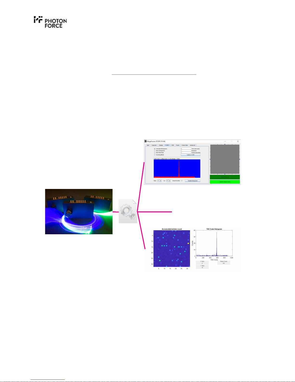
Photon Force supports a number of ways to use your PF32 camera, all built around our camera
driver. A Java demo application is provided, which can be used to quickly test the camera, view a
video stream, capture histograms, and explore the camera settings. The Java application is
discussed later in this guide. A MATLAB® wrapper is provided for scientific use, allowing the
camera to be operated and data acquired from within the MATLAB® environment. Demo
functions are provided for acquiring both live video for display, and high speed streaming of data
for analysis. The MATLAB® wrapper is discussed in a dedicated guide, available from the setup
link above. Finally, you may use the Photon Force API to communicate with the PF32 camera from
your own software. Please consult the API guide provided via the setup page above.
Illustration of software components.
PF32 camera
Driver
DLL
Java demo application
Your software
Photon Force MATLAB® wrapper
Page 5

Page 5 of 28
S O F T W AR E I N S T A L L A T I O N – M I C R O S O F T W I N D O W S
The PF32 application and USB driver are designed for 64-bit Windows 10, but are also compatible
with older versions of Windows. 32-bit Windows and Linux versions are available upon request.
Software installation is performed in two steps:
1. Obtain up-to-date Java Runtime Environment (JRE).
2. Install PF32 driver and demo application.
Page 6
Page 6 of 28
J A V A R U N T I M E EN V I R O N M E N T I N S T A L L A T I O N
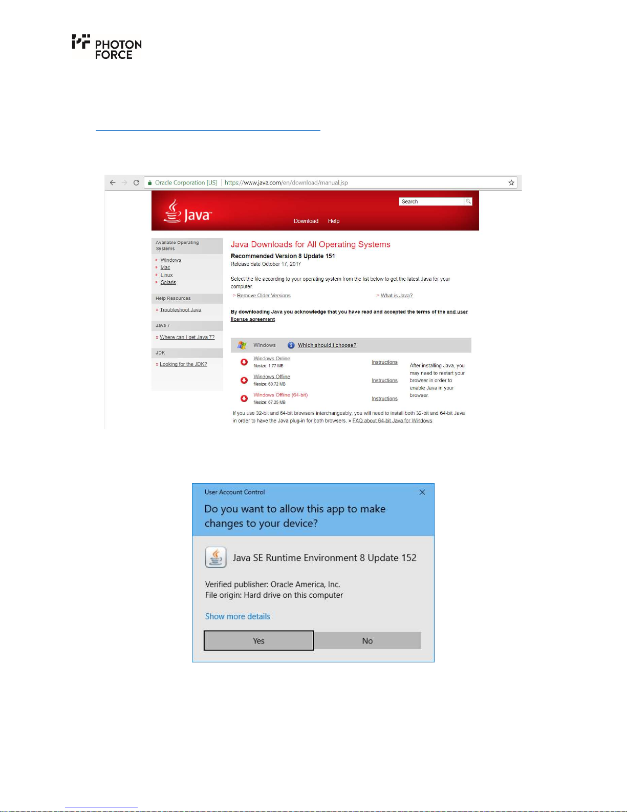
The PF32 Java application requires the Java Runtime Environment (JRE). If not installed already,
please download the JRE from the Oracle Java web site:
https://www.java.com/en/download/manual.jsp
To install the Oracle Java Runtime Environment, download and run the Windows Offline (64-bit)
installer.
The installation of the JRE requires the following steps:
1. Run the installer and provide the necessary administrator rights to allow the installation.
Page 7
Page 7 of 28
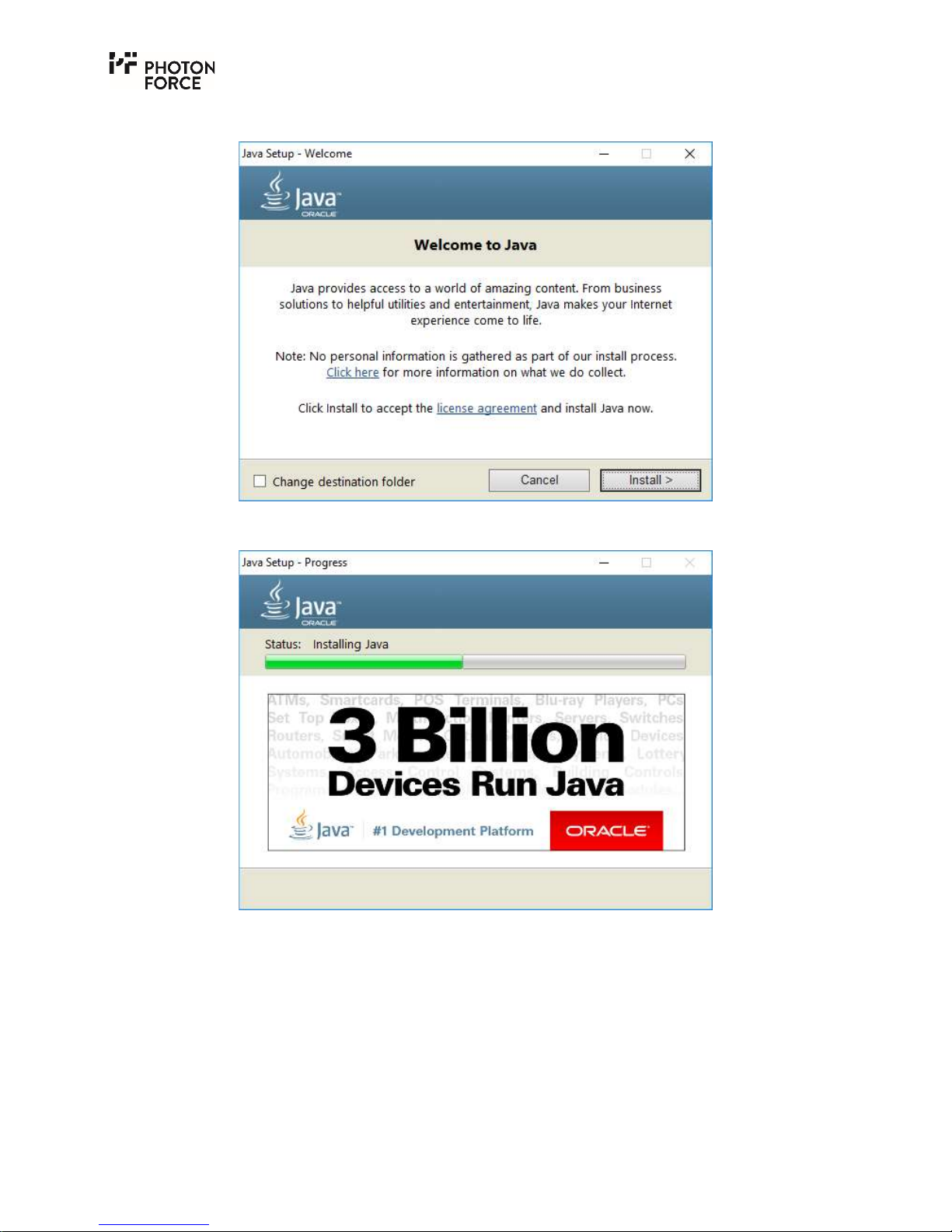
2. Accept the license agreement.
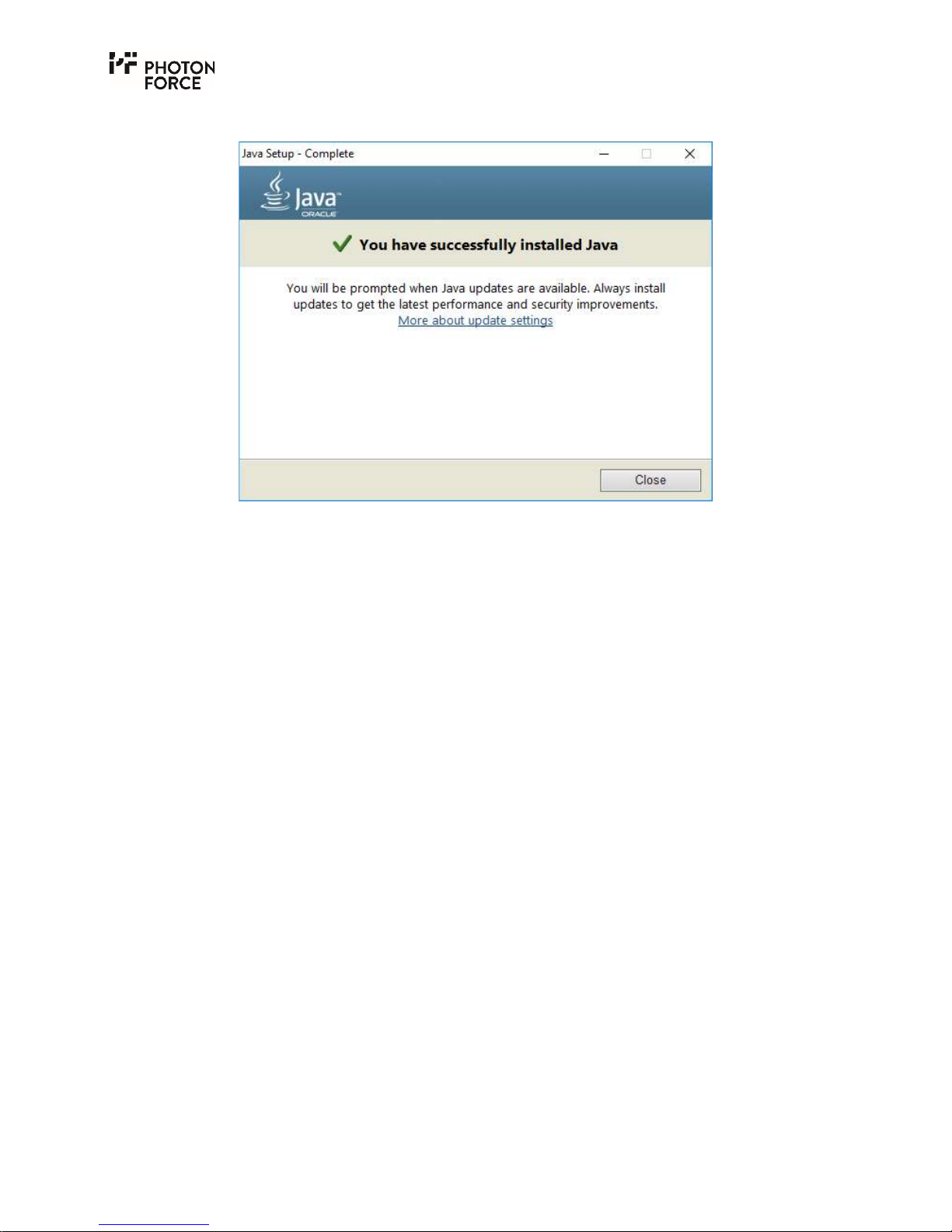
3. Wait for the installer to finish.
Page 8
Page 8 of 28
4. Close the installer and proceed to the installation of the PF32 software package.
Page 9
Page 9 of 28
P F 3 2 S O F T W A RE P A C K A G E I N S T A L L A T I O N
Regular updates for the USB driver and Java demo application are offered to Photon Force
customers.
Run the PF32 installer. The latest version 1.4.9 for Windows is called:
PF32-1.4.9-win64.exe
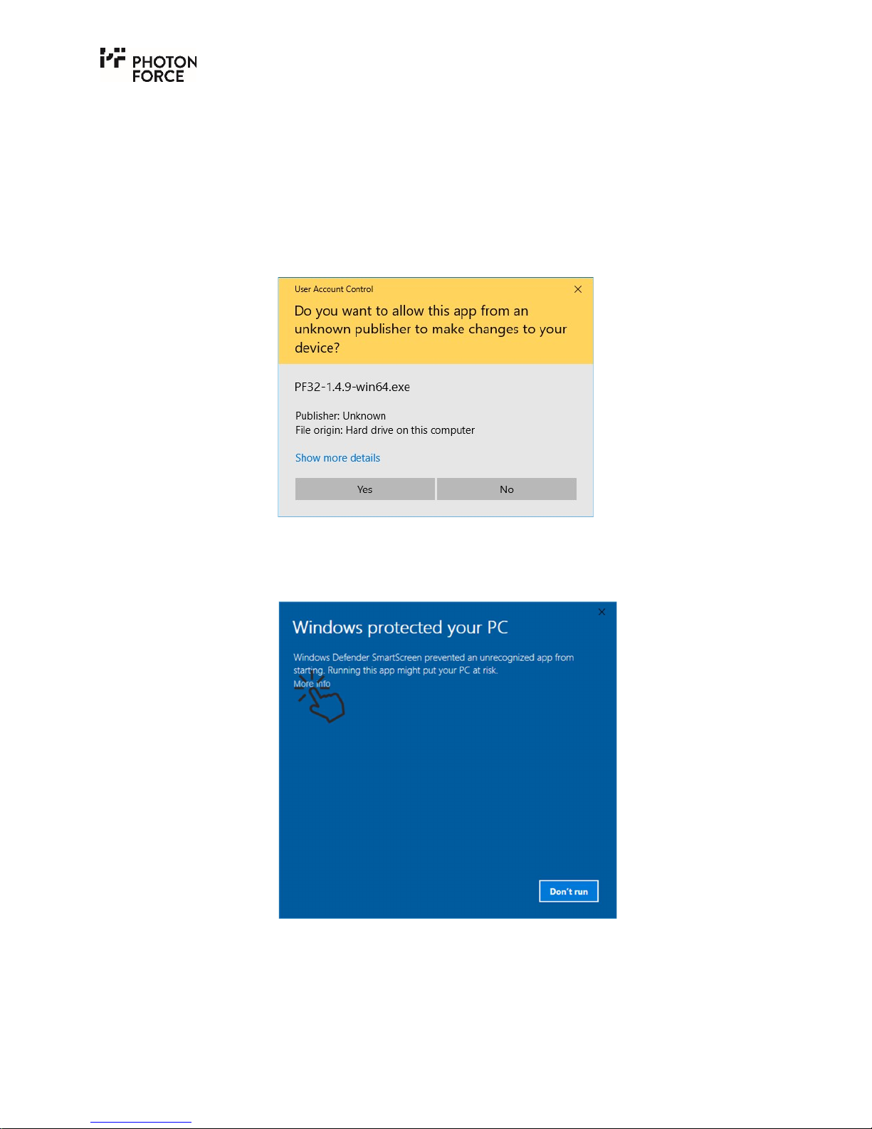
1. The installation may require Administrator permission. Press "Yes" when the following
window appears and provide the Administrator password if required.
2. The installer might not start immediately and you may need to provide the appropriate
permissions along the way. If so, Windows will guide the process. The following window
may appear before the installer starts. Click the "More info" link to proceed.
Page 10
Page 10 of 28
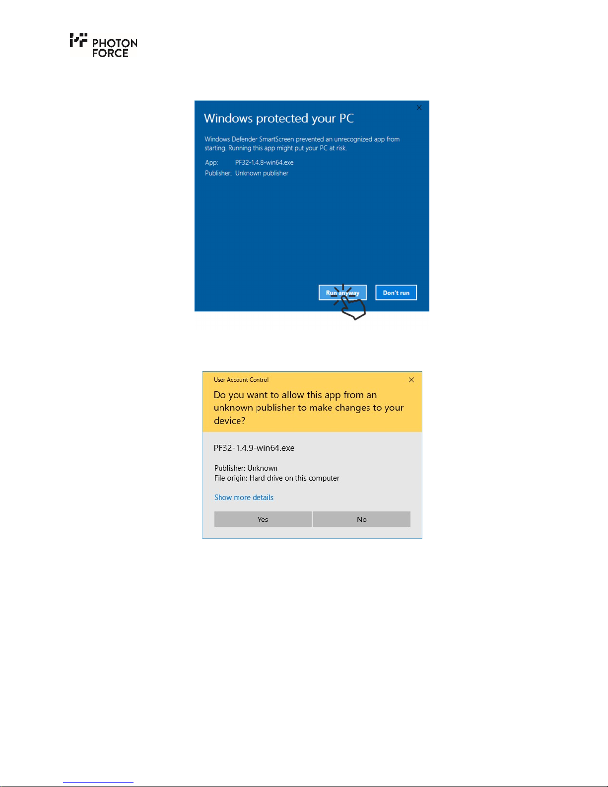
3. A new button "Run anyway" appears. Click this button to override the default Windows
security setting.
4. Once again, you might be asked for the permission to install the PF32 software package.
Press “Yes” to proceed.
Page 11
Page 11 of 28
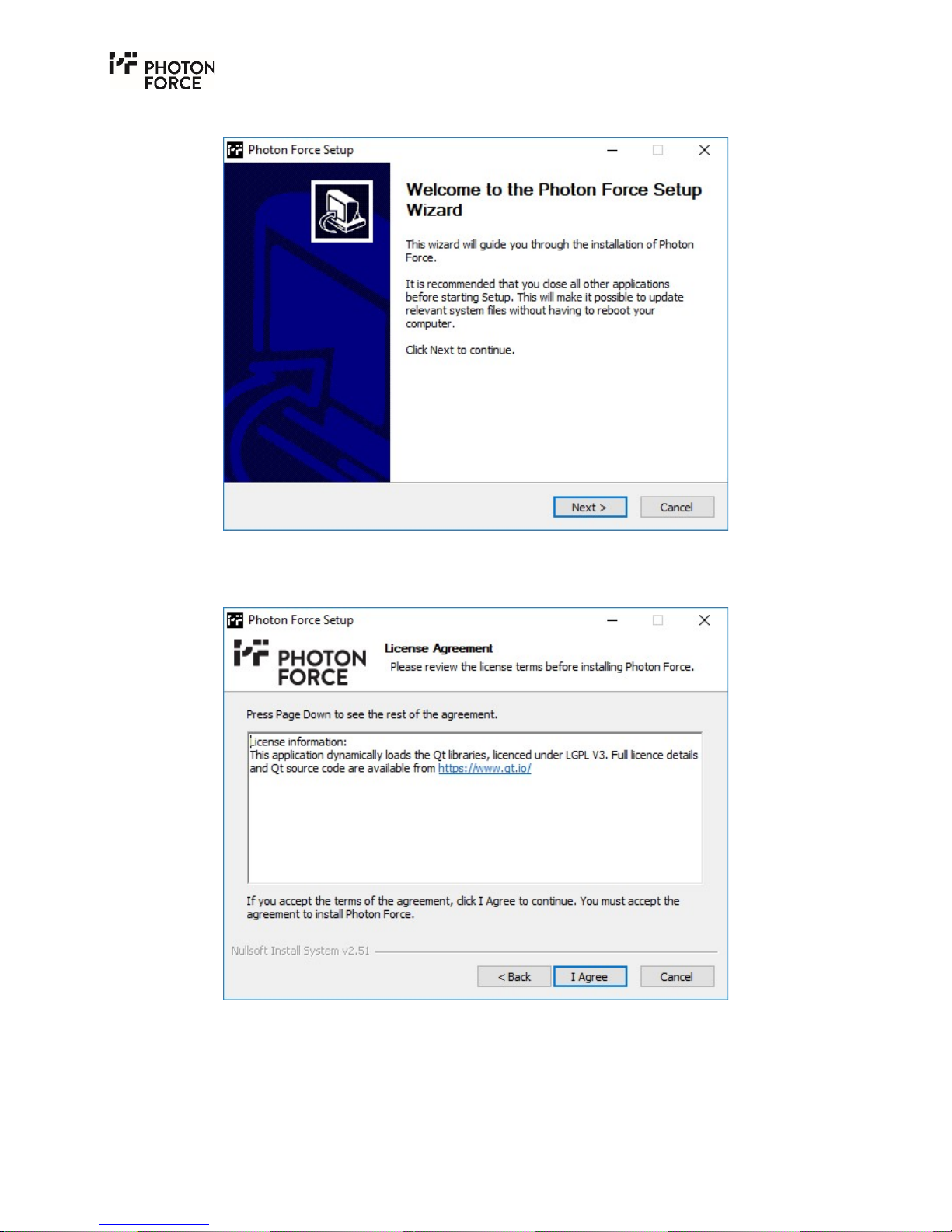
5. Start the installation.
6. Accept the license agreement.
Page 12
Page 12 of 28
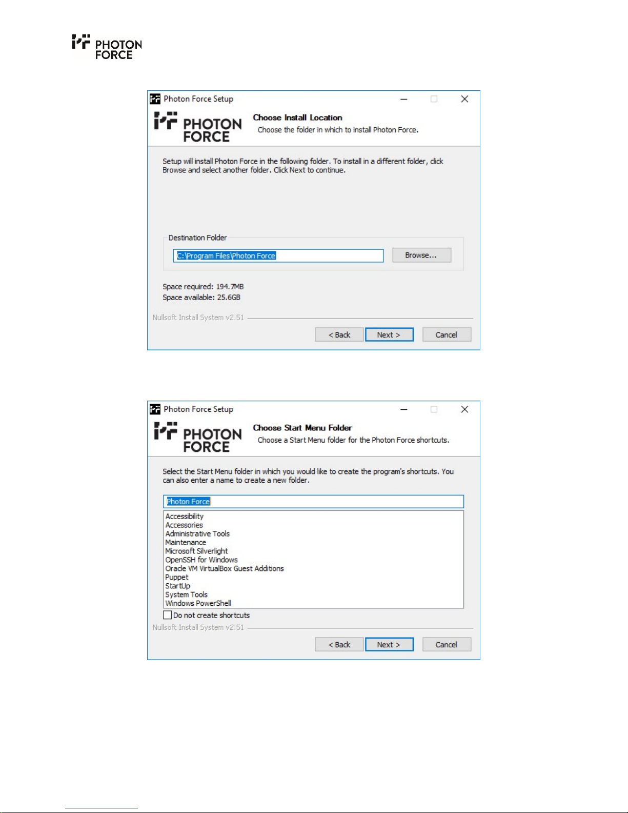
7. Choose the installation folder.
8. Choose the start menu folder in which Photon Force shortcuts will be created.
Page 13
Page 13 of 28
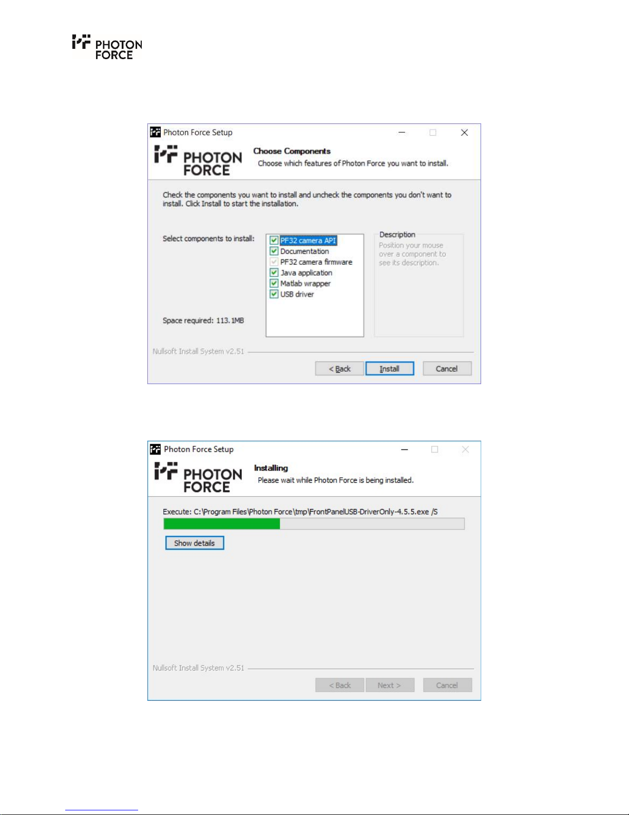
9. Choose the components to install. The PF32 camera API is the software interface to the
camera. The Java application is a standalone demo application and GUI to run the camera.
The USB driver is required for operating system communication with the camera.
10. Wait for the installer to finish.
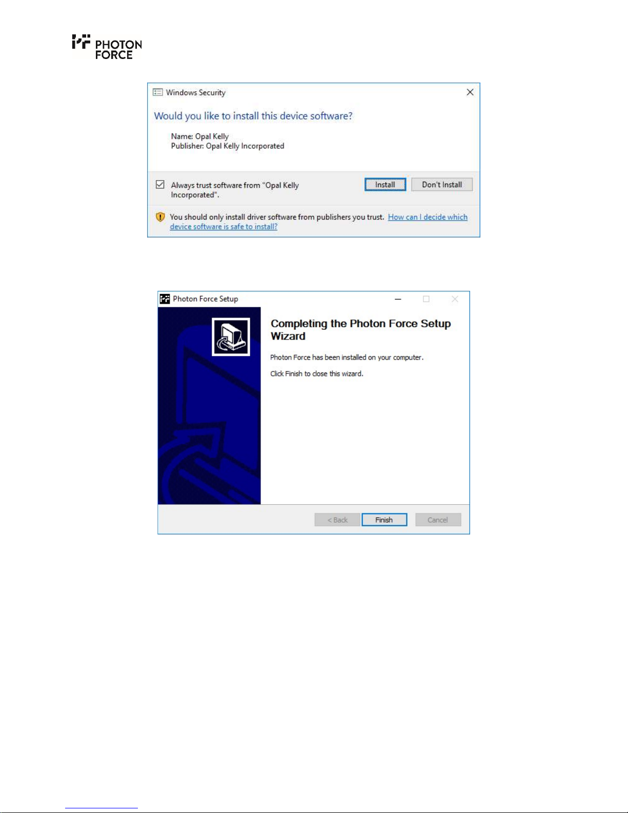
11. Provide permission to install the driver.
Page 14
Page 14 of 28
12. Finish the installer.
Page 15
Page 15 of 28
P F 3 2 J A V A DE M O A P P L I C A T I O N F I R S T R U N
USB3 and Power Connection
Included within the PF32 carry-case are the 5V power supply (PSU) and the USB3 cable. It is
crucial that no other PSU is used since an incorrect voltage, polarity, or current may irreversibly
damage the PF32.
Please connect the USB3 cable and PSU. Windows will then perform a driver installation the first
time the board is connected.
Start the PF32 Java Win_x64 application.
Windows may prevent the application from loading the first time you attempt to run it. This is
due to an inbuilt security feature preventing the execution of unverified programs. Permission
will have to be granted to run the PF32 Java Application as explained below. If the program does
not start at all, ensure that the Java Runtime Environment is installed first (see here).
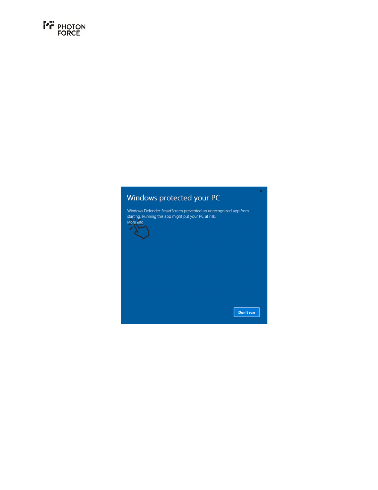
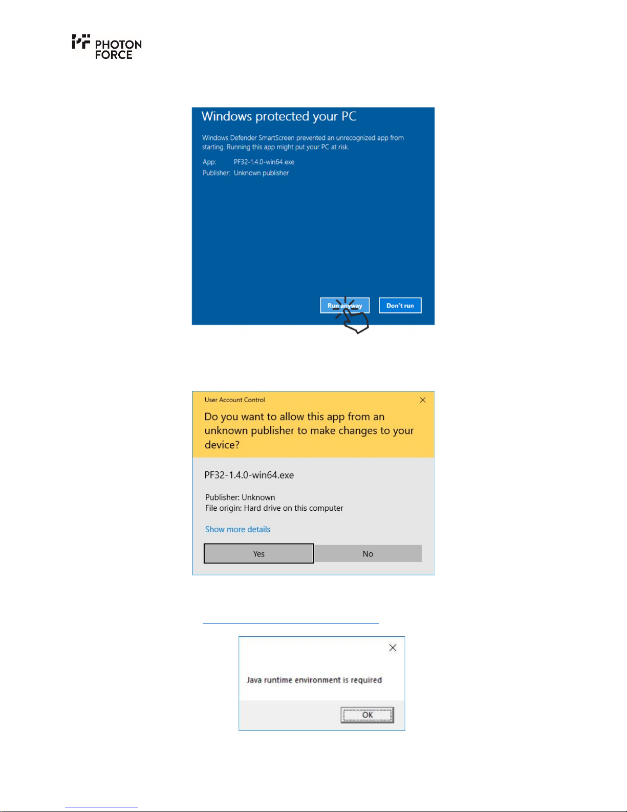
1. The following window will appear on the first run of the PF32 Java Win_x64 demo
application. Click the "More info" link to proceed.
Page 16
Page 16 of 28
2. A new button "Run anyway" appears. Click this button to override the default Windows
security setting.
3. Finally, one last prompt window appears, where permission to run the software must be
granted. This may require an Administrator password.
4. Note that if the Java Runtime Environment has not been installed, the following warning
will be displayed. Please install a Java Runtime Environment as described above before
continuing (see Java Runtime Environment Installation).
Page 17
Page 17 of 28
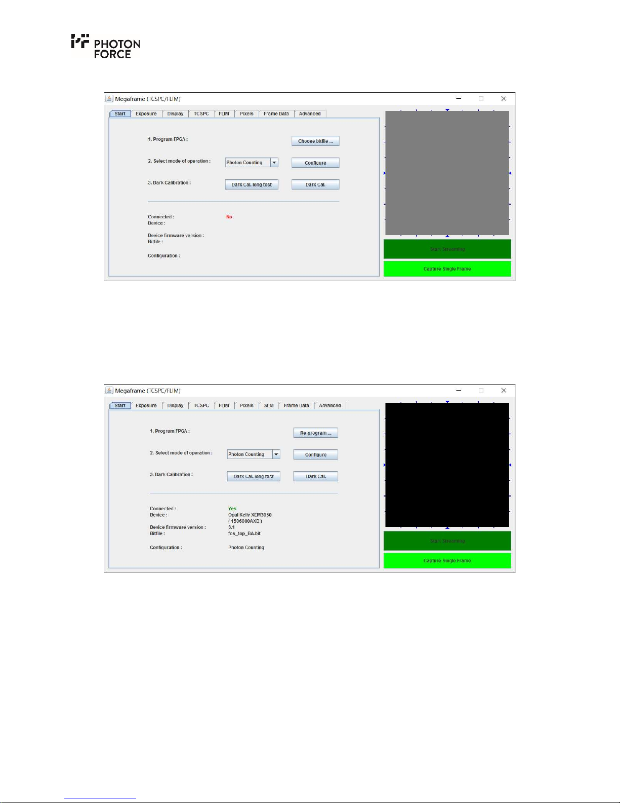
5. Once the application starts, the following window appears.
6. Ensure the PF32 system is connected and powered on.
7. Click “Choose bitfile” and select the “PF32_USB3.bit” file provided, which contains the
camera firmware. Note that other controls in the application are unresponsive until the
camera firmware has been programmed, and the connection status will display “NO”. If
programming is successful, the connection status will change to “YES” and the FPGA type,
serial number and system operating mode will be displayed.
By default, the system is configured in a photon counting mode, which does not provide timing
information. Settings may be changed by selecting the desired mode of operation from the dropdown menu and pressing configure, or by changing the appropriate settings in the control tabs.
At this point, in order to see an image within the software, you should attach a lens to the PF32.
The PF32 has a CS-mount on the front. Should you wish you to use a C-mount lens, an appropriate
spacer should be used. To use any other lens, adapters must be purchased separately.
Page 18
Page 18 of 28
C O N N E CT I N G T H E C A M E R A F O R T C S P C M O D E
The instructions for USB3 and Power Connection should already have been followed.
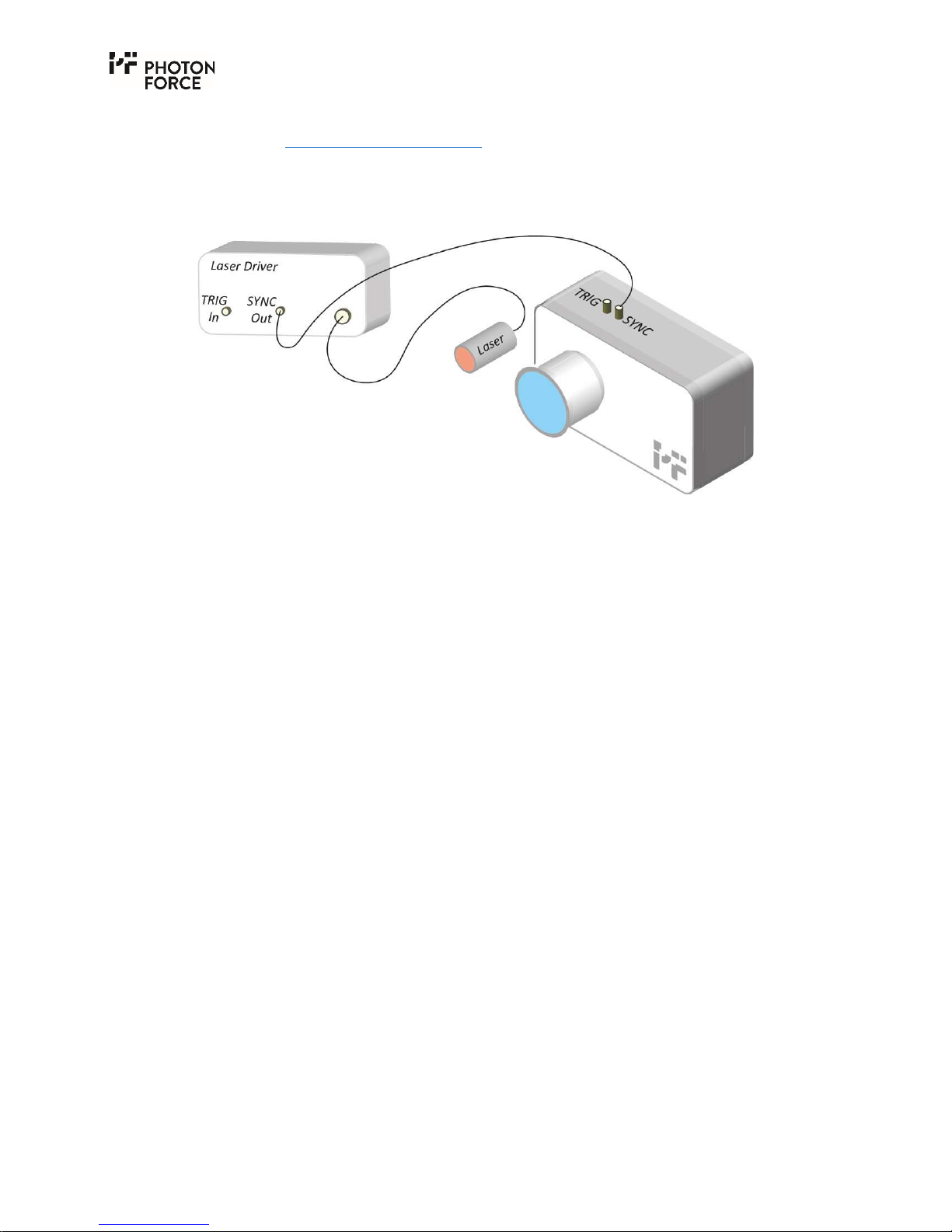
In order to synchronise your camera with a pulsed light source, there are a number of options
available to the user. The most common of these is for the camera to be used in slave mode,
whereby the timing reference is provided by an external source as shown in the example below:
PF32 Camera in slave TCSPC mode where the timing synchronisation is provided by the same
clock as the light source.
In this case, the laser driver provides an electrical synchronisation reference pulse to the camera
at the same time as the laser sends a pulse of light (to the target/sample depending on the
application). The camera, as standard, accepts +3.3V (measured with 50 Ω load) pulses as
reference through the SMA connector labelled “SYNC”, but can be configured to accept other
signals (NIM, for example) upon request. Care should be taken to ensure that the limits for the
synchronisation signal are not exceeded to prevent damage to the electronics and sensor. Note,
in the above example, the laser driver can also be triggered by an external source. In this case,
the external source could trigger both the PF32 and the laser, provided the electrical pulse is
within the limits stated in the PF32 SYNC Input Configuration document (supplied separately
according to the SYNC options chosen by the customer).
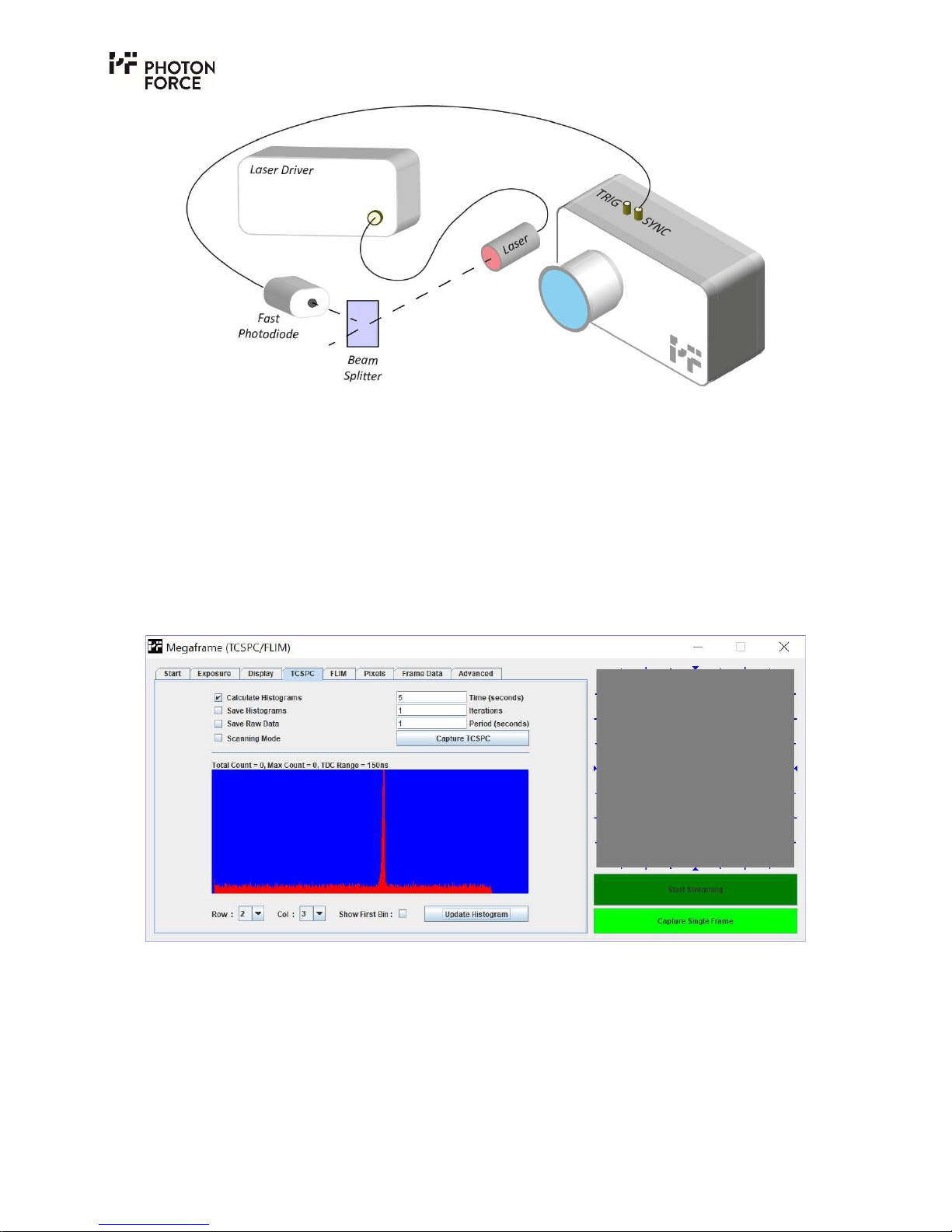
If the laser control unit does not include a synchronisation output, a portion of the outgoing beam
can be split off (using an appropriate beam splitter) and directed on to a fast photodiode with
circuitry that can provide an appropriate output signal. Photon Force can advise on the choice of
trigger detector. Please contact us if you have any queries in this area.
Page 19
Page 19 of 28
PF32 camera in slave TCSPC mode where the timing synchronisation signal is provided by an
optical detector (fast photodiode, for example) with an appropriate output.
With the SYNC signal connected to the camera, open the Java software. As before, program the
FPGA by clicking on “Choose bitfile”, then select “PF32_USB3.bit”. Check that the sync rate
displayed on the start tab matches the expected value. In the box “Select mode of operation” select
“TCSPC (laser master)” then click “Configure”. Navigate to the TCSPC tab.
The simplest test to observe time-correlated data is to direct the pulsed light source, safely and
diffusely, at a wall or scattering surface and image this surface with the camera. Within the TCSPC
tab, click on “Capture TCSPC”. The default measurement time is 5 seconds, after which, the
measurement will stop. Next, select which pixel’s histogram you wish to see by selecting a “Row”
and “Col” value and click “Update Histogram”. Below is an example of a TCSPC histogram.
PF32 Java application displaying a captured histogram.
Page 20
Page 20 of 28
J A V A D EM O A P P L I C A T I O N G U I DE
O V E R V I E W
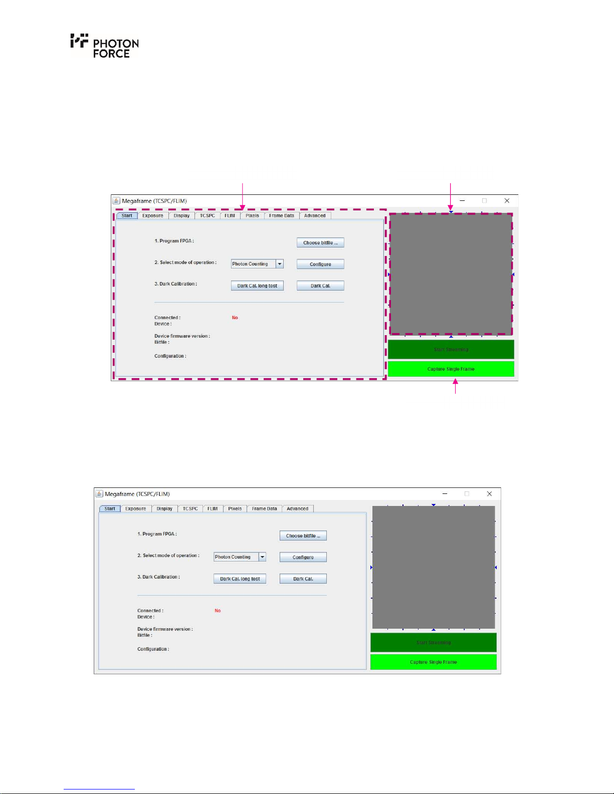
The PF32 Java demo application GUI is shown below. It consists of a tab-based control panel, an
image display area, and streaming controls. These features are discussed in turn. Note that none
of the features will be active until a PF32 camera has been connected, powered on, and configured
using the start tab as described below.
Overview of the main PF32 Java demo application GUI features.
S TA R T T A B
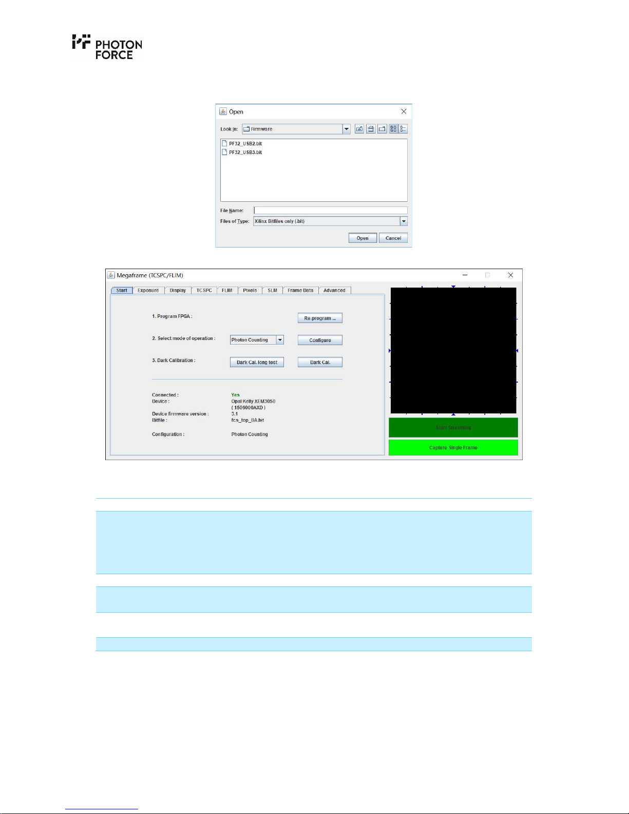
When the PF32 Java GUI is launched, it will initially display the Start tab, as shown below. The
start tab displays status information, and provides controls to load the camera’s firmware and set
the operating mode.
PF32 Java application Start tab, with no PF32 camera connected.
Note that none of the software features are active until a PF32 camera has been connected, and
the firmware loaded. With a PF32 camera connected and powered on, press the “Choose bitfile”
Image display area Tabbed control panel
Streaming controls
Page 21
Page 21 of 28
button, and select the appropriate firmware bit file for your PF32 camera (either USB2 or USB3)
from the dialog as shown below.
The start tab should then update as follows:
PF32 Java application Start tab, with a camera connected and configured.
The following status information is provided in the start tab:
Item Description
Connected: Indicates PF32 connection status. This will display either:
NO – PF32 camera is either not connected, or firmware has not
yet been loaded.
YES – PF32 camera is connected, and firmware has been
loaded.
Device: Displays the camera’s internal serial number.
Device firmware version: Displays the version number of the camera’s internal USB
firmware.
Bitfile: Displays the filename of the firmware bit file which has been
loaded.
Configuration: Provides confirmation of the camera’s mode of operation.
The camera’s operating mode may be quickly set by choosing the desired setting from the “Select
mode of operation” drop down box, and pressing the “Configure” button. If successful, the new
configuration will be indicated on the “Configuration” display mentioned above. The following
camera modes are available:
Page 22

Page 22 of 28
Mode Description
Photon Counting (default) In this mode, the camera pixels are configured to count the
number of detected photons each frame. 7-bit counters are
provided, delivering a maximum count of 127 photons per
pixel.
TCSPC (laser master) The camera is configured in Time Correlated Single Photon
Counting (TCSPC) mode, where each pixel timestamps the first
photon detected during each frame. In this mode, the camera
requires a sync signal to be provided from the laser, connected
via the SYNC input.
TCSPC (system master) The camera is configured in TCSPC mode as above, but
generates a trigger output signal provided on the TRIG port.
Test pulse counting A test mode, not required for user operation. In this mode, all
pixels count electrical test pulses instead of photons. The
number of test pulses is programmable via the “Advanced” tab.
Test data 1/2 Further electrical test modes, not required for user operation.
Additionally, an experimental dark count rate (DCR) calibration feature is provided. Before
conducting a DCR calibration, the lens cap should be fitted to the camera, ideally with the camera
situated in a completely dark environment. The Dark Cal. button may then be pressed. This
instructs the software to acquire data for a defined exposure time, and save the resulting image
as a dark reference. The ‘Dark Cal. Filter’ setting on the display tab allows this to be subtracted
from the images displayed.
I M A G E D I SP L A Y A N D S T R E A M I N G CO N T R O L S
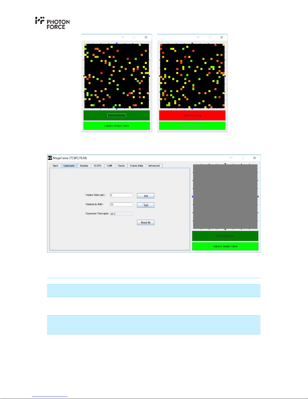
Once a PF32 camera has been connected, powered on, and configured using the start tab as
described above, images may be captured. The streaming controls may be used to capture single
frames or stream video rate images from the sensor, for live display in the image display area.
Clearly, a PC monitor cannot display the frame rates achievable with the PF32 camera, so this
feature should be considered as a useful preview tool, for example when aligning optics.
Page 23
Page 23 of 28
PF32 Java application image display area and streaming controls, showing idle (left) and
streaming in progress (right).
E X P O S U R E T A B
PF32 Java application Exposure tab.
The exposure tab allows the camera’s frame time to be set, specified in microseconds (µs). Please
note that unless otherwise specified, the camera provides a minimum frame time of 2µs.
Setting Description
Frame Time (µs) Specifies the sensor’s frame time in microseconds. Valid values
are 2 to 8,000µs.
Frames to Add This specifies the number of sensor frames which will be
digitally summed by the camera to produce each frame
transmitted to the PC. Valid values are 1 to 50,000.
Exposure Time (µs) Displays the total exposure time for each frame received by the
PC, defined as the sensor frame time multiplied by the number
of frames to add.
Page 24
Page 24 of 28
D I S P L A Y T A B
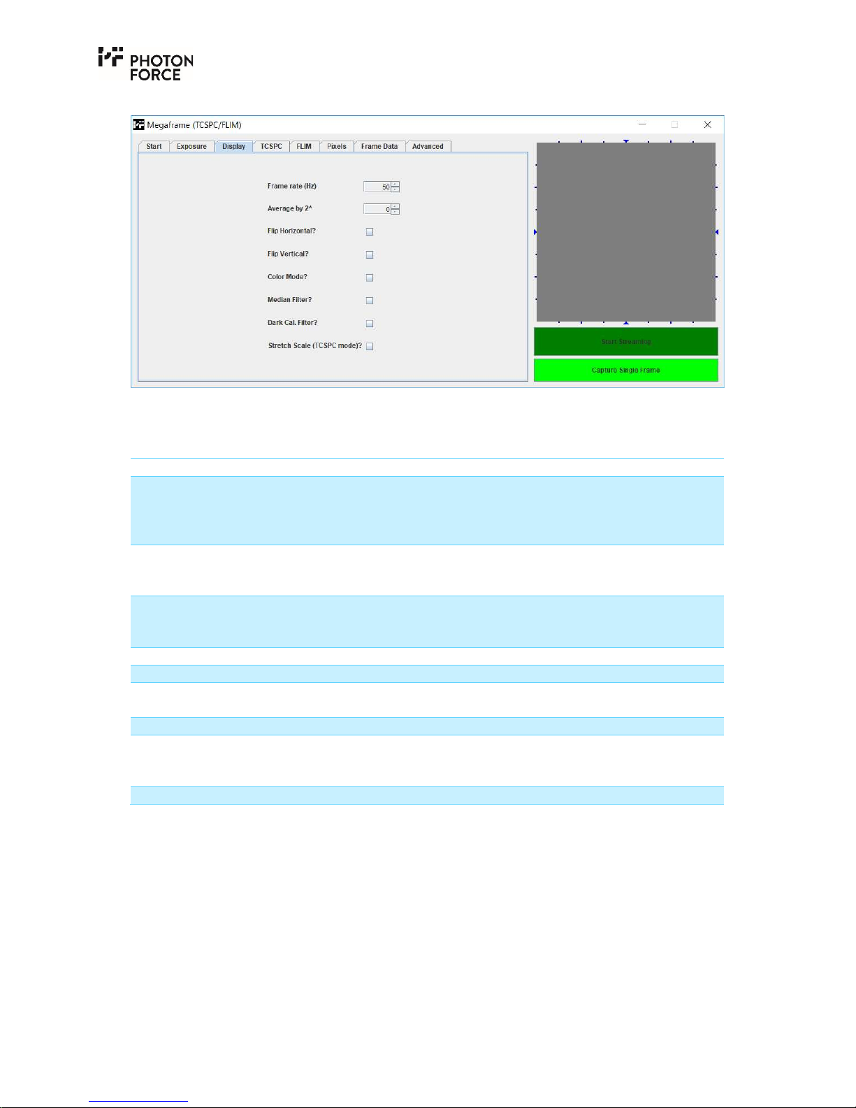
PF32 Java application Display tab.
The display tab provides settings controlling how image data is displayed in the image display
area.
Setting Description
Frame rate (Hz) Specifies the target frame rate that the application should
attempt to display in streaming mode. Note that the refresh
rate of most displays is around 60Hz, so streaming faster than
this is not useful.
Average by 2^ This setting instructs the Java application to average a number
of sensor frames, specified as 2N, and display the result instead
of raw data. This should not be applied in TCSPC mode.
Exposure Time (µs) Displays the total exposure time for each frame received by the
PC, defined as the sensor frame time multiplied by the number
of frames to add.
Flip Horizontal Inverts the displayed image horizontally.
Flip Vertical Inverts the displayed image vertically.
Color Mode When checked, enables false colour mode. This is enabled
automatically in TCSPC mode.
Median Filter Applies a noise filter to the displayed image data.
Dark Cal. Filter Applies a basic dark count (DCR) correction. Note that this
experimental feature is only operational if DCR calibration
data has been generated for your PF32 camera.
Stretch Scale (TCSPC mode)
T C S P C T A B
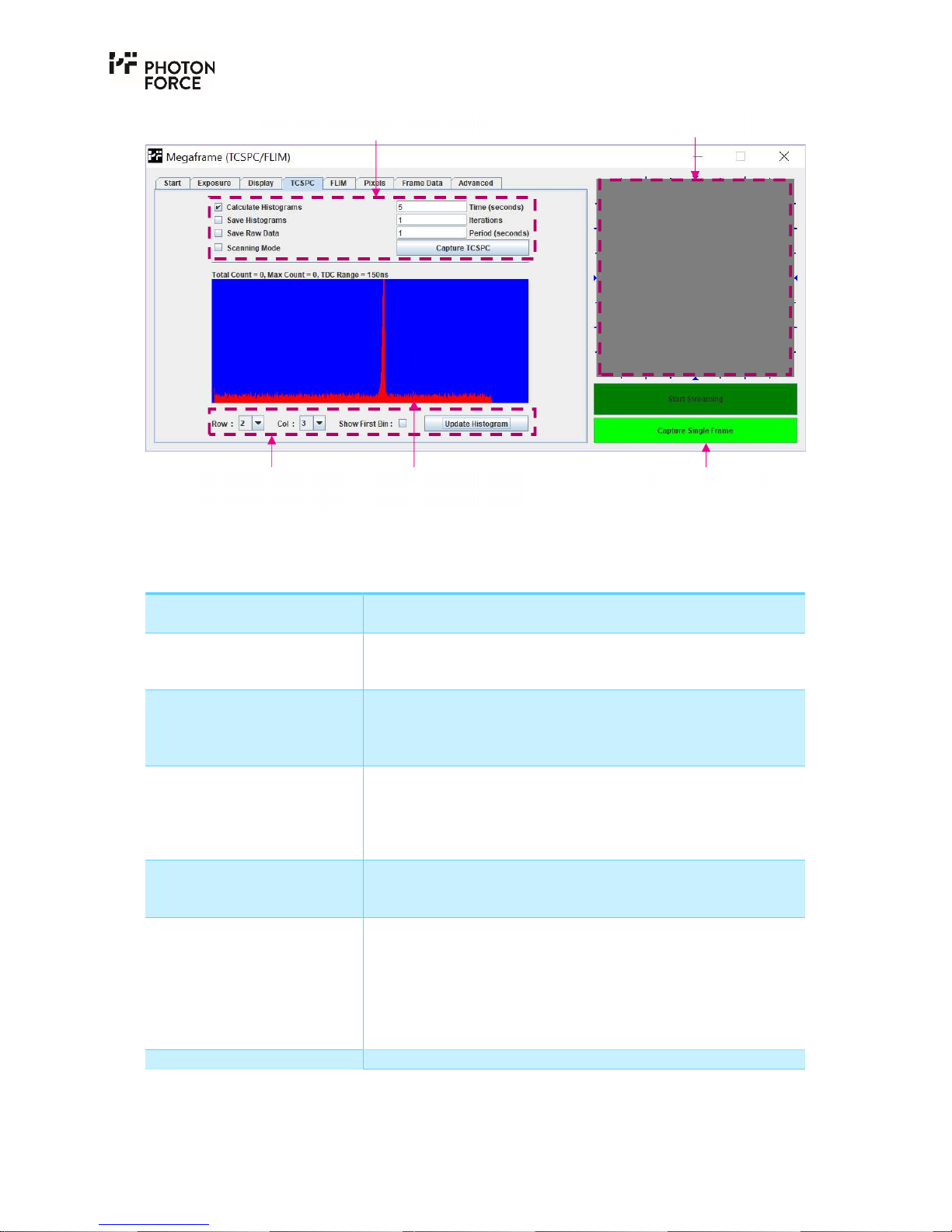
The TCSPC tab provides a basic means of capturing data at high speed from the sensor, and
performing software-based histogramming of the data received by each pixel. Note that high
speed capture and histogram generation is independent of the image display area and streaming
controls discussed previously. The image display area will not update during histogram capture.
Also note that if the camera is streaming to the image display area when “Capture TCSPC” is
pressed, streaming and image display will pause while histogram capture is in progress, and
resume automatically afterwards.
Page 25
Page 25 of 28
PF32 Java application TCSPC tab.
The following histogram controls are available:
Setting Description
Calculate Histograms Enabled by default. If disabled, the software will acquire data
but not calculate histograms.
Save Histograms If enabled, the software will save the generated histogram data
in a CSV format. Alternative file formats may be available on
request.
Save Raw Data If enabled, the sensor will save the captured raw frame data to
disk in CSV format. Note that enabling this feature may
significantly slow down data acquisition, depending on the
speed at which your PC can write to disk.
Time(seconds) Histogram update rate, specified in seconds. For example, if set
to 1 second, then a number of frames corresponding to 1
second of sensor exposure time will be acquired. Note that data
acquisition may take longer than the specified exposure time,
depending on the sensor frame rate and USB bus bandwidth.
Iterations Specifies the number of iterations of data capture to complete.
For example, if set to 10, then 10 sets of data of the specified
length will be captured.
Period (seconds) Optionally, a value may be given here to capture the number of
iterations within the specified interval (i.e., if time is set to 1,
iterations to 10, and period to 10, then a 1-second exposure
time will be captured followed by a 9-second pause before the
next data capture, repeated 10 times). Note that the period
setting will not take effect if set to less than the integration
time.
Capture TCSPC Starts the requested histogram capture.
Image display area Histogram acquisition controls
Streaming controls
Histogram display
controls
Single pixel
histogram display
Page 26
Page 26 of 28
The Histogram tab is able to display histogram data for one pixel at a time. This may be set using
the histogram display controls at the bottom of the tab.
Setting Description
Row Specifies the pixel for which histogram data is to be displayed.
Col
Show First Bin If enabled, histogram bin 0 will be included in the histogram
display. Otherwise, bin 0 will not be included. Since bin 0
corresponds to no photon being detected in TCSPC mode, it is
not typically useful to include this. At low light levels, the
number of no photon (bin 0) counts may vastly exceed the
values in other histogram bins.
Update Histogram When the “Row”, “Col”, or “Show First Bin” settings are
changed, the Update Histogram button should be pressed to
refresh the histogram display. Note that before a histogram can
be displayed, “Calculate Histograms” must be enabled and data
must be captured using “Capture TCSPC”.
F R A M E D A T A T A B
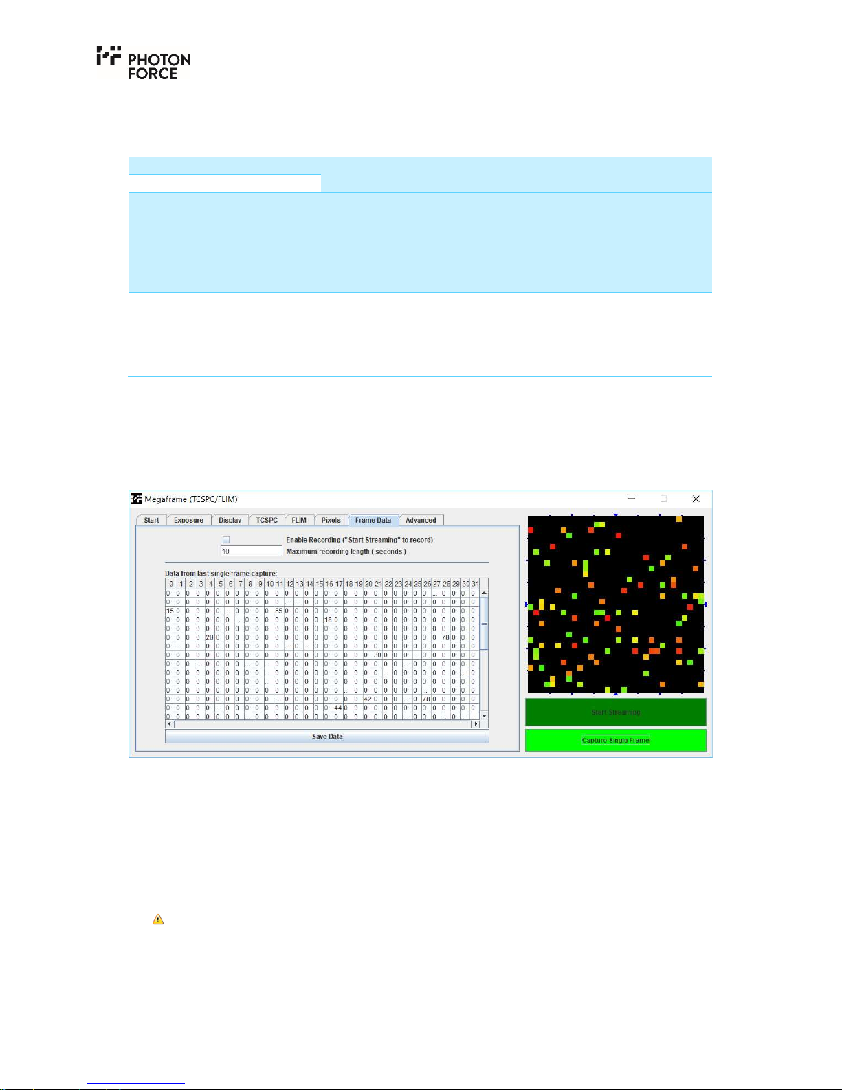
The frame data tab provides a means of inspecting the raw individual pixel values within the GUI.
Every time the ‘Capture Single Frame’ streaming control is clicked, this will be updated. Please
note that the raw values are not updated during streaming.
PF32 Java application Frame Data tab.
A D V A N C E D T A B – B I A S S E T U P
The Advanced tab contains 3 sub-tabs which provide access to a number of low level features not
typically required for customer applications. This tab should be ignored unless specifically
advised by Photon Force Ltd. or your distributor.
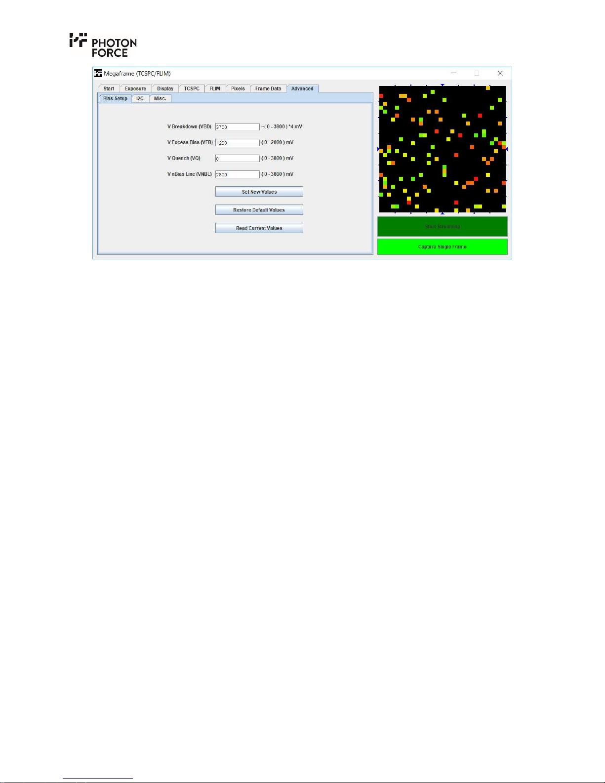
The bias tab allows the various configuration voltages to be adjusted to tune the performance of
your PF32 for specific applications.
Do not adjust the bias voltages without first consulting Photon Force or your authorized
distributor. Doing so may result in damage to your camera.
Page 27
Page 27 of 28
PF32 Java application Bias Setup tab.
SPAD Negative Bias Voltage (VBD)
This is the supply normally set at the reverse breakdown voltage of the detector. Note that the
sensor applies a gain of 4, i.e. the default value of 3700 = 14,800mV.
SPAD Excess Bias Voltage (VEB)
The excess bias voltage defines how far beyond the reverse breakdown voltage the SPADs are
biased. This is typically set to 1.2V.
SPAD Quench Time Control Voltage (VQUENCH)
VQUENCH allows the sensor's avalanche quenching or recharge time (dead time) to be adjusted.
For maximum quenching speed, VQUENCH should be set to the default value of 0V. Increasing
this voltage lengthens the recharge time.
TDC Supply Regulation Voltage (VNBIASLINE)
The TDC supply regulation voltage (VNBIASLINE) controls the camera’s TDC speed or histogram
bin width. The default value of 2800mV corresponds to approximately a 55ps TDC bin width.
Decreasing this value results in a slower TDC speed and wider bin width.
Page 28

Photon Force Ltd.
34 Melville Street,
Edinburgh
Scotland, UK,
EH3 7HA
 Loading...