

Photon Focus MV0 CMOSIS Series, MV0-D2048x1088-C01-160-G2, MV0-D2048-C01-160-G2 User Manual

Photonfocus
MV0 CMOSIS Camera Series
CMOS camera series with GigE Interface
MV0-D2048x1088-C01-160-G2
MV0-D2048-C01-160-G2
MAN078 12/2018 V1.1

All information provided in this manual is believed to be accurate and reliable. No
responsibility is assumed by Photonfocus AG for its use. Photonfocus AG reserves the right to
make changes to this information without notice.
Reproduction of this manual in whole or in part, by any means, is prohibited without prior
permission having been obtained from Photonfocus AG.
2 of 111 MAN078 12/2018 V1.1

Contents
1 Preface 7
1.1 IMPORTANT NOTICE! . . . . . . . . . . . . . . . . . . . . . . . . . . . . . . . . . . . . . 7
1.2 About Photonfocus . . . . . . . . . . . . . . . . . . . . . . . . . . . . . . . . . . . . . . 8
1.3 Contact . . . . . . . . . . . . . . . . . . . . . . . . . . . . . . . . . . . . . . . . . . . . . 8
1.4 Sales Offices . . . . . . . . . . . . . . . . . . . . . . . . . . . . . . . . . . . . . . . . . . 8
1.5 Further information . . . . . . . . . . . . . . . . . . . . . . . . . . . . . . . . . . . . . . 8
1.6 Legend . . . . . . . . . . . . . . . . . . . . . . . . . . . . . . . . . . . . . . . . . . . . . 9
2 Introduction 11
2.1 Introduction . . . . . . . . . . . . . . . . . . . . . . . . . . . . . . . . . . . . . . . . . . 11
2.2 Camera Naming Convention . . . . . . . . . . . . . . . . . . . . . . . . . . . . . . . . . 11
2.3 Camera list . . . . . . . . . . . . . . . . . . . . . . . . . . . . . . . . . . . . . . . . . . . 11
3 Product Specification 13
3.1 Introduction . . . . . . . . . . . . . . . . . . . . . . . . . . . . . . . . . . . . . . . . . . 13
3.2 Feature Overview . . . . . . . . . . . . . . . . . . . . . . . . . . . . . . . . . . . . . . . 15
3.3 Technical Specification . . . . . . . . . . . . . . . . . . . . . . . . . . . . . . . . . . . . 15
3.3.1 Absolute Maximum Ratings . . . . . . . . . . . . . . . . . . . . . . . . . . . . . 17
3.3.2 Electrical Characteristics . . . . . . . . . . . . . . . . . . . . . . . . . . . . . . . 17
3.3.3 Spectral Response . . . . . . . . . . . . . . . . . . . . . . . . . . . . . . . . . . . 18
3.4 RGB Bayer Pattern Filter (color models) . . . . . . . . . . . . . . . . . . . . . . . . . . 20
4 Image Acquisition 21
4.1 Overview . . . . . . . . . . . . . . . . . . . . . . . . . . . . . . . . . . . . . . . . . . . . 21
4.1.1 Vocabulary . . . . . . . . . . . . . . . . . . . . . . . . . . . . . . . . . . . . . . . 21
4.1.2 Structure . . . . . . . . . . . . . . . . . . . . . . . . . . . . . . . . . . . . . . . . 21
4.1.3 Image Acquisition, Frame and Exposure Control Parameters . . . . . . . . . . 22
4.1.4 Image Acquisition, Frame and Exposure Trigger . . . . . . . . . . . . . . . . . 23
4.1.5 Image Acquisition, Frame and Exposure Status . . . . . . . . . . . . . . . . . . 23
4.2 Acquisition Control . . . . . . . . . . . . . . . . . . . . . . . . . . . . . . . . . . . . . . 24
4.2.1 Acquisition Start and Stop Commands, Acquisition Mode and Acquisition
Frame Count . . . . . . . . . . . . . . . . . . . . . . . . . . . . . . . . . . . . . . 24
4.2.2 Acquisition Frame Rate and Acquisition Frame Rate Enable . . . . . . . . . . 24
4.2.3 Acquisition Start Trigger . . . . . . . . . . . . . . . . . . . . . . . . . . . . . . . 25
4.2.4 Acquisition End Trigger . . . . . . . . . . . . . . . . . . . . . . . . . . . . . . . . 26
4.2.5 Acquisition Control Output Signals . . . . . . . . . . . . . . . . . . . . . . . . . 26
4.3 Frame Control . . . . . . . . . . . . . . . . . . . . . . . . . . . . . . . . . . . . . . . . . 27
4.3.1 Frame Start Trigger . . . . . . . . . . . . . . . . . . . . . . . . . . . . . . . . . . 27
4.3.2 Frame Burst Start Trigger . . . . . . . . . . . . . . . . . . . . . . . . . . . . . . . 27
4.3.3 Frame Burst End Trigger . . . . . . . . . . . . . . . . . . . . . . . . . . . . . . . 28
4.3.4 Frame Control Output Signals . . . . . . . . . . . . . . . . . . . . . . . . . . . . 29
4.4 Exposure Control . . . . . . . . . . . . . . . . . . . . . . . . . . . . . . . . . . . . . . . 30
MAN078 12/2018 V1.1 3 of 111

CONTENTS
4.4.1 Exposure Mode . . . . . . . . . . . . . . . . . . . . . . . . . . . . . . . . . . . . 30
4.4.2 Exposure Start Trigger . . . . . . . . . . . . . . . . . . . . . . . . . . . . . . . . 30
4.4.3 Exposure End Trigger . . . . . . . . . . . . . . . . . . . . . . . . . . . . . . . . . 30
4.4.4 Exposure Control Output Signals . . . . . . . . . . . . . . . . . . . . . . . . . . 31
4.5 Overlapped Image Acquisition Timing . . . . . . . . . . . . . . . . . . . . . . . . . . . 32
4.6 Acquisition-, Frame- and Exposure-Trigger Configuration . . . . . . . . . . . . . . . . 34
4.6.1 Trigger Source Selection . . . . . . . . . . . . . . . . . . . . . . . . . . . . . . . 34
4.6.2 Trigger Software . . . . . . . . . . . . . . . . . . . . . . . . . . . . . . . . . . . 35
4.6.3 Trigger Mode . . . . . . . . . . . . . . . . . . . . . . . . . . . . . . . . . . . . . 35
4.6.4 Trigger Activation . . . . . . . . . . . . . . . . . . . . . . . . . . . . . . . . . . . 35
4.6.5 Trigger Divider . . . . . . . . . . . . . . . . . . . . . . . . . . . . . . . . . . . . . 36
4.6.6 Trigger Delay . . . . . . . . . . . . . . . . . . . . . . . . . . . . . . . . . . . . . . 36
4.7 Software Signal Pulse and User Output . . . . . . . . . . . . . . . . . . . . . . . . . . 37
5 Counter & Timer 39
5.1 Counter . . . . . . . . . . . . . . . . . . . . . . . . . . . . . . . . . . . . . . . . . . . . . 39
5.1.1 Counter Usage . . . . . . . . . . . . . . . . . . . . . . . . . . . . . . . . . . . . . 39
5.1.2 Counter Status . . . . . . . . . . . . . . . . . . . . . . . . . . . . . . . . . . . . . 40
5.1.3 Counter Active, -Start and -End Signal . . . . . . . . . . . . . . . . . . . . . . . 40
5.1.4 Counter Reset . . . . . . . . . . . . . . . . . . . . . . . . . . . . . . . . . . . . . 40
5.1.5 Counter Event Source . . . . . . . . . . . . . . . . . . . . . . . . . . . . . . . . . 41
5.1.6 Counter Trigger Source . . . . . . . . . . . . . . . . . . . . . . . . . . . . . . . . 42
5.1.7 Counter Reset Source . . . . . . . . . . . . . . . . . . . . . . . . . . . . . . . . . 43
5.2 Timer . . . . . . . . . . . . . . . . . . . . . . . . . . . . . . . . . . . . . . . . . . . . . . 44
5.2.1 Timer Usage . . . . . . . . . . . . . . . . . . . . . . . . . . . . . . . . . . . . . . 45
5.2.2 Timer Status . . . . . . . . . . . . . . . . . . . . . . . . . . . . . . . . . . . . . . 45
5.2.3 Timer Active, -Start and -End Signal . . . . . . . . . . . . . . . . . . . . . . . . 45
5.2.4 Timer Reset . . . . . . . . . . . . . . . . . . . . . . . . . . . . . . . . . . . . . . . 46
5.2.5 Timer Trigger Source . . . . . . . . . . . . . . . . . . . . . . . . . . . . . . . . . 46
6 I/O Control 47
6.1 Input Signal Path . . . . . . . . . . . . . . . . . . . . . . . . . . . . . . . . . . . . . . . 47
6.2 Output Signal Path . . . . . . . . . . . . . . . . . . . . . . . . . . . . . . . . . . . . . . 47
7 Action Control 49
7.1 Action Command Usage . . . . . . . . . . . . . . . . . . . . . . . . . . . . . . . . . . . 49
7.2 Action Control Output . . . . . . . . . . . . . . . . . . . . . . . . . . . . . . . . . . . . 50
8 Image Format Control 51
8.1 Region of Interest (ROI) . . . . . . . . . . . . . . . . . . . . . . . . . . . . . . . . . . . 51
9 Frame Rate 53
9.1 Exposure time is dominant . . . . . . . . . . . . . . . . . . . . . . . . . . . . . . . . . . 53
9.2 Image size is dominant . . . . . . . . . . . . . . . . . . . . . . . . . . . . . . . . . . . . 53
9.3 Maximum Frame Rate . . . . . . . . . . . . . . . . . . . . . . . . . . . . . . . . . . . . 53
10 High Dynamic Range Mode (HDR) 55
10.1 Multiple Slope Mode (High Dynamic Range) . . . . . . . . . . . . . . . . . . . . . . . 55
4 of 111 MAN078 12/2018 V1.1

CONTENTS
11 Image Data Processing 57
11.1 Overview . . . . . . . . . . . . . . . . . . . . . . . . . . . . . . . . . . . . . . . . . . . . 57
11.2 Column FPN Correction . . . . . . . . . . . . . . . . . . . . . . . . . . . . . . . . . . . . 59
11.2.1 Enable / Disable the Column FPN Correction . . . . . . . . . . . . . . . . . . . 59
11.2.2 Calibration of the Column FPN Correction . . . . . . . . . . . . . . . . . . . . . 59
11.2.3 Storing the calibration in permanent memory . . . . . . . . . . . . . . . . . . 60
11.3 Gain and Offset . . . . . . . . . . . . . . . . . . . . . . . . . . . . . . . . . . . . . . . . 60
11.4 Grey Level Transformation (LUT) . . . . . . . . . . . . . . . . . . . . . . . . . . . . . . 61
11.4.1 Gain . . . . . . . . . . . . . . . . . . . . . . . . . . . . . . . . . . . . . . . . . . . 61
11.4.2 Gamma . . . . . . . . . . . . . . . . . . . . . . . . . . . . . . . . . . . . . . . . . 63
11.4.3 User-defined Look-up Table . . . . . . . . . . . . . . . . . . . . . . . . . . . . . 64
11.4.4 Region LUT and LUT Enable . . . . . . . . . . . . . . . . . . . . . . . . . . . . . 64
11.5 Crosshairs . . . . . . . . . . . . . . . . . . . . . . . . . . . . . . . . . . . . . . . . . . . . 67
11.6 Status Line and Image Information . . . . . . . . . . . . . . . . . . . . . . . . . . . . . 69
11.6.1 Image Average Value . . . . . . . . . . . . . . . . . . . . . . . . . . . . . . . . . 69
11.6.2 Status Line Format . . . . . . . . . . . . . . . . . . . . . . . . . . . . . . . . . . 69
11.6.3 Camera Type Codes . . . . . . . . . . . . . . . . . . . . . . . . . . . . . . . . . . 71
11.7 Test Images . . . . . . . . . . . . . . . . . . . . . . . . . . . . . . . . . . . . . . . . . . . 72
11.7.1 Ramp . . . . . . . . . . . . . . . . . . . . . . . . . . . . . . . . . . . . . . . . . . 72
11.7.2 LFSR . . . . . . . . . . . . . . . . . . . . . . . . . . . . . . . . . . . . . . . . . . . 72
11.7.3 Troubleshooting using the LFSR . . . . . . . . . . . . . . . . . . . . . . . . . . . 72
12 Precautions 75
12.1 IMPORTANT NOTICE! . . . . . . . . . . . . . . . . . . . . . . . . . . . . . . . . . . . . . 75
13 Hardware Interface 79
13.1 Absolute Maximum Ratings . . . . . . . . . . . . . . . . . . . . . . . . . . . . . . . . . 79
13.2 Electrical Characteristics . . . . . . . . . . . . . . . . . . . . . . . . . . . . . . . . . . . 79
13.3 GigE Camera Connector . . . . . . . . . . . . . . . . . . . . . . . . . . . . . . . . . . . 79
13.4 Power Over Ethernet (PoE) . . . . . . . . . . . . . . . . . . . . . . . . . . . . . . . . . . 79
13.5 Status Indicator (GigE cameras) . . . . . . . . . . . . . . . . . . . . . . . . . . . . . . . 80
13.6 I/O Connector . . . . . . . . . . . . . . . . . . . . . . . . . . . . . . . . . . . . . . . . . 81
13.6.1 Overview . . . . . . . . . . . . . . . . . . . . . . . . . . . . . . . . . . . . . . . . 81
13.6.2 Single-ended Line Input . . . . . . . . . . . . . . . . . . . . . . . . . . . . . . . 82
13.6.3 Single-ended Line Output . . . . . . . . . . . . . . . . . . . . . . . . . . . . . . 83
13.6.4 Master / Slave Camera Connection . . . . . . . . . . . . . . . . . . . . . . . . . 84
14 Mechanical Considerations 85
14.1 Mechanical Interface . . . . . . . . . . . . . . . . . . . . . . . . . . . . . . . . . . . . . 85
14.1.1 Cameras with GigE Interface . . . . . . . . . . . . . . . . . . . . . . . . . . . . . 85
14.2 Optical Interface . . . . . . . . . . . . . . . . . . . . . . . . . . . . . . . . . . . . . . . . 86
14.2.1 Cleaning the Sensor . . . . . . . . . . . . . . . . . . . . . . . . . . . . . . . . . . 86
15 Troubleshooting 89
15.1 No images can be acquired . . . . . . . . . . . . . . . . . . . . . . . . . . . . . . . . . 89
15.1.1 No acquisition due to no triggers . . . . . . . . . . . . . . . . . . . . . . . . . . 89
16 Standards Compliance 91
16.1 Directives and General Standards . . . . . . . . . . . . . . . . . . . . . . . . . . . . . . 91
16.2 Country-specific Information . . . . . . . . . . . . . . . . . . . . . . . . . . . . . . . . 91
16.2.1 For customers in the USA . . . . . . . . . . . . . . . . . . . . . . . . . . . . . . . 91
16.2.2 For customers in Canada . . . . . . . . . . . . . . . . . . . . . . . . . . . . . . . 92
16.2.3 Pour utilisateurs au Canada . . . . . . . . . . . . . . . . . . . . . . . . . . . . . 92
MAN078 12/2018 V1.1 5 of 111

CONTENTS
16.3 Life support applications . . . . . . . . . . . . . . . . . . . . . . . . . . . . . . . . . . . 92
17 Warranty 93
17.1 Warranty Terms . . . . . . . . . . . . . . . . . . . . . . . . . . . . . . . . . . . . . . . . 93
17.2 Warranty Claim . . . . . . . . . . . . . . . . . . . . . . . . . . . . . . . . . . . . . . . . 93
17.3 Breach of Warranty . . . . . . . . . . . . . . . . . . . . . . . . . . . . . . . . . . . . . . 93
18 Support and Repair 95
18.1 Technical Support . . . . . . . . . . . . . . . . . . . . . . . . . . . . . . . . . . . . . . . 95
18.2 Repair and obtaining an RMA Number . . . . . . . . . . . . . . . . . . . . . . . . . . . 95
18.3 Temporal Abandoning and Scrapping . . . . . . . . . . . . . . . . . . . . . . . . . . . 95
19 References 97
A Pinouts 99
A.1 I/O Connector . . . . . . . . . . . . . . . . . . . . . . . . . . . . . . . . . . . . . . . . . 99
A.2 GigE Connector . . . . . . . . . . . . . . . . . . . . . . . . . . . . . . . . . . . . . . . . 99
B Camera Timing 101
B.1 Timed Exposure Mode Camera Timing . . . . . . . . . . . . . . . . . . . . . . . . . . . 101
C Use Cases 103
C.1 Acquisition . . . . . . . . . . . . . . . . . . . . . . . . . . . . . . . . . . . . . . . . . . . 103
C.1.1 Camera runs in "free-running" mode . . . . . . . . . . . . . . . . . . . . . . . 103
C.1.2 Camera runs in "constant frame rate" mode . . . . . . . . . . . . . . . . . . . 103
C.1.3 Camera runs in triggered mode . . . . . . . . . . . . . . . . . . . . . . . . . . . 104
C.1.4 Camera runs in burst triggered mode . . . . . . . . . . . . . . . . . . . . . . . 104
C.1.5 Triggered controlled exposure mode . . . . . . . . . . . . . . . . . . . . . . . . 105
C.2 Timer . . . . . . . . . . . . . . . . . . . . . . . . . . . . . . . . . . . . . . . . . . . . . . 106
C.2.1 Strobe Signal Output . . . . . . . . . . . . . . . . . . . . . . . . . . . . . . . . . 106
C.3 Counter . . . . . . . . . . . . . . . . . . . . . . . . . . . . . . . . . . . . . . . . . . . . . 107
C.3.1 Counter Reset . . . . . . . . . . . . . . . . . . . . . . . . . . . . . . . . . . . . . 107
C.3.2 Image Counter . . . . . . . . . . . . . . . . . . . . . . . . . . . . . . . . . . . . . 107
C.3.3 Real Time Counter . . . . . . . . . . . . . . . . . . . . . . . . . . . . . . . . . . 107
C.3.4 Missed Trigger Counter . . . . . . . . . . . . . . . . . . . . . . . . . . . . . . . . 108
C.4 Look-Up Table (LUT) . . . . . . . . . . . . . . . . . . . . . . . . . . . . . . . . . . . . . 109
C.4.1 Overview . . . . . . . . . . . . . . . . . . . . . . . . . . . . . . . . . . . . . . . . 109
C.4.2 Full ROI LUT . . . . . . . . . . . . . . . . . . . . . . . . . . . . . . . . . . . . . . 109
C.4.3 Region LUT . . . . . . . . . . . . . . . . . . . . . . . . . . . . . . . . . . . . . . . 109
C.4.4 User defined LUT settings . . . . . . . . . . . . . . . . . . . . . . . . . . . . . . 109
C.4.5 Predefined LUT settings . . . . . . . . . . . . . . . . . . . . . . . . . . . . . . . 110
D Document Revision History 111
6 of 111 MAN078 12/2018 V1.1

Preface
1.1 IMPORTANT NOTICE!
READ THE INSTRUCTIONS FOR USE BEFORE
OPERATING THE CAMERA
1
STORE THE INSTRUCTIONS FOR USE FOR
FURTHER READING
Photonfocus AG
Bahnhofplatz 10
CH-8853 Lachen SZ
Switzerland
www.photonfocus.com
info@photonfocus.com
+41 – 55 451 00 00
MAN078 12/2018 V1.1 7 of 111

1 Preface
1.2 About Photonfocus
The Swiss company Photonfocus is one of the leading specialists in the development of CMOS
image sensors and corresponding industrial cameras for machine vision.
Photonfocus is dedicated to making the latest generation of CMOS technology commercially
available. Active Pixel Sensor (APS) and global shutter technologies enable high speed and
high dynamic range (120 dB) applications, while avoiding disadvantages like image lag,
blooming and smear.
Photonfocus’ product range is complemented by custom design solutions in the area of camera
electronics and CMOS image sensors.
Photonfocus is ISO 9001 certified. All products are produced with the latest techniques in order
to ensure the highest degree of quality.
1.3 Contact
Photonfocus AG, Bahnhofplatz 10, CH-8853 Lachen SZ, Switzerland
Sales Phone: +41 55 451 00 00 Email: sales@photonfocus.com
Support Phone: +41 55 451 00 00 Email: support@photonfocus.com
Table 1.1: Photonfocus Contact
1.4 Sales Offices
Photonfocus products are available through an extensive international distribution network
and through our key account managers. Contact us via email at sales@photonfocus.com.
1.5 Further information
Photonfocus reserves the right to make changes to its products and documentation without notice. Photonfocus products are neither intended nor certified for
use in life support systems or in other critical systems. The use of Photonfocus
products in such applications is prohibited.
Photonfocus and LinLog®are registered trademarks of Photonfocus AG.
CameraLink®and GigE Vision®are a registered mark of the Automated Imaging Association. Product and company names mentioned herein are trademarks
or trade names of their respective companies.
Reproduction of this manual in whole or in part, by any means, is prohibited
without prior permission having been obtained from Photonfocus AG.
Photonfocus can not be held responsible for any technical or typographical errors.
8 of 111 MAN078 12/2018 V1.1

1.6 Legend
In this documentation the reader’s attention is drawn to the following icons:
Important note, additional information
Important instructions
General warning, possible component damage hazard
Warning, electric shock hazard
Warning, fire hazard
1.6 Legend
MAN078 12/2018 V1.1 9 of 111

1 Preface
10 of 111 MAN078 12/2018 V1.1

2
M V 0 - D 2 0 4 8 x 1 0 8 8 C - C 0 1 - 1 6 0 - G 2
P r e f i x 1
P r e f i x 2
S e n s o r w i d t h & h e i g h t
( o p t i o n a l )
S e n s o r t y p e
C a m e r a
s p e e d
I n t e r f a c e t y p e
S e n s o r
M a n u f a c t u r e r
S e n s o r
F a m i l y
Introduction
2.1 Introduction
This manual describes standard Photonfocus MV0 CMOSIS series cameras that have a Gigbit
Ethernet (GigE) interface. The cameras contain CMV2000 and CMV4000 from CMOSIS.
2.2 Camera Naming Convention
The naming convention of the MV0 CMOSIS camera series is summarized in Fig. 2.1.
Figure 2.1: Camera naming convention
Prefix1 Camera platform and usage prefix. The following prefix are available for this camera
series: MV0 with form factor 30x30.
Prefix2 Camera family specifier. The following specifiers are used in this manual: "D": digital
standard area scan cameras.
Sensor width Width of image sensor of the camera.
Sensor type Sensor types specification: "I": NIR enhanced sensors, "C": color cameras.
Cameras without sensor type specifier have a standard monochrome sensor.
Sensor Manufacturer Sensor manufacturer. "C": CMOSIS
Sensor Family Sensor family of the prior indicated manufacturer. "01": CMV2000/4000 series
Camera speed The camera speed is usually the product of the camera interface clock in MHz
and the number of parallel interface channels (taps).
Interface type Interface type specification: "CL": CameraLink®, "G2": Gigabit Ethernet
(GigEVision), "U3": USB3 (USB3 Vision).
2.3 Camera list
A list of all cameras covered in this manual is shown in Table 2.1.
MAN078 12/2018 V1.1 11 of 111

2 Introduction
Name Resolution Frame Rate Notes
MV0-D2048x1088-C01-160-G2 2048 x 1088 50 fps
1)
Gigabit Ethernet 2 MP
monochrome standard camera.
MV0-D2048-C01-160-G2 2048 x 2048 26 fps
1)
Gigabit Ethernet 4 MP
monochrome standard camera.
Table 2.1: Camera models covered by this manual (Footnotes:1)frame rate at at full resolution)
12 of 111 MAN078 12/2018 V1.1

3
Product Specification
3.1 Introduction
The Photonfocus MV0 CMOSIS GigE camera series is built around the CMOS image sensors
CMV2000 and CMV4000 from CMOSIS. They provide a resolution of 2048 x 1088 (CMV2000)
and 2048 x 2048 (CMV4000) pixels. The camera series is optimized for low light conditions and
there are standard monochrome, NIR enhanced monochrome (I) and colour (C) models. The
cameras are aimed at standard applications in industrial image processing where high
sensitivity and high frame rates are required.
The principal advantages are:
• Resolution of 2048x1088 (CMV2000) and 2048x2048 (CMV4000) pixels
• Optimized for low light conditions
• Spectral range: monochrome standard: 350 - 900 nm, NIR enhanced 350 - 970 nm
• Global shutter
• Micro lenses
• Color cameras: Bayer pattern filter and cut off filter @ 660nm
• Gigabit Ethernet interface, GigE Vision and GenICam compliant
• Power Over Ethernet (PoE).
• Frame rates at maximal resolution 50 fps (CMV2000) and 26 fps (CMV4000)
• I/O capabilities: 1 isolated input and 1 isolated output
• 2 look-up tables (12-to-8 bit) on user-defined image region (Region-LUT)
• Crosshairs overlay on the image
• Image information and camera settings inside the image (status line)
• Software provided for setting and storage of camera parameters
• The rugged housing at a compact size of 30 x 30 x 53 mm3makes the Photonfocus MV0
CMOSIS GigE camera series the perfect solution for applications in which space is at a
premium.
The general specification and features of the camera are listed in the following sections.
MAN078 12/2018 V1.1 13 of 111

3 Product Specification
Figure 3.1: Photonfocus MV0 CMOSIS GigE camera series
14 of 111 MAN078 12/2018 V1.1

3.2 Feature Overview
3.2 Feature Overview
The general specification and features of the camera are listed in the following sections. The
detailed description of the camera features is given in the following chapters.
Characteristics Photonfocus MV0 CMOSIS GigE Camera Series
Interface Gigabit Ethernet (PoE), GigE Vision and GenICam compliant
Camera Control GigE Vision Suite
Trigger Modes Software Trigger / External isolated trigger input
• Greyscale / colour resolution 10 bit / 8 bit
• Region of Interest (ROI)
• 2 look-up tables (12-to-8 bit) on user-defined image region
Features
(Region-LUT)
• Test pattern (LFSR and grey level ramp)
• Image information and camera settings inside the image (status line)
• Crosshairs overlay on the image
• 1 isolated trigger input and 1 isolated output
Table 3.1: Feature overview
3.3 Technical Specification
MAN078 12/2018 V1.1 15 of 111

3 Product Specification
2 MPix Cameras 4 MPix Cameras
Sensor Manufacturer CMOSIS
Sensor Type CMV2000 CMV4000
Technology CMOS active pixel
Scanning system progressive scan
Optical format / diagonal 2/3” (12.75 mm diagonal) 1" (15.92 mm diagonal)
Resolution 2048x1088 pixels 2048x1088 pixels
Pixel size 5.5 µm x 5.5 µm
Active optical area 11.26 mm x 5.98 mm 11.26mm x 11.26 mm
Full well capacity 11 ke
Readout noise 13 e
−
−
Spectral range standard sensor < 350 to 900 nm (to 10 % of peak responsivity)
Spectral range of (I) models < 350 to 970 nm (to 10 % of peak responsivity)
Spectral range of colour models 390 to 670 nm (to 10 % of peak responsivity)
Sensitivity (with micro lenses) 5.56 V / lux.s (with micro lenses @ 550 nm)
Optical fill factor 42 % (without micro lenses)
Dark current 125 e−/s @ 25°C
Dynamic range 58.5 dB
Micro lenses Yes
Colour format (C) cameras RGB Bayer Raw Data Pattern
Characteristic curve Linear, Piecewise linear (multiple slope)
Shutter mode global shutter
Sensor bit depth 10 bit
Maximal frame rate
1)
50 fps 26 fps
Camera pixel formats 10 / 8 bit
Digital gain 0.1 to 15.99 (Fine Gain)
Exposure time range 10 µs ... 419 ms
Table 3.2: General specification of the Photonfocus MV0 CMOSIS GigE camera series (Footnotes:1)at full
resolution)
16 of 111 MAN078 12/2018 V1.1

3.3 Technical Specification
Photonfocus MV0 CMOSIS GigE Camera Series
Operating temperature / moisture 0°C ... 50°C / 20 ... 80 % (camera needs to be connected
to heat sink)
Storage temperature / moisture -25°C ... 60°C / 20 ... 95 %
Trigger signal input range +5 .. +20 V DC
Maximal power consumption < 4.2 W
Lens mount C-Mount
I/O Inputs 1x Opto-isolated
I/O Outputs 1x Opto-isolated
Dimensions 30 x 30 x 54.1 mm
3
Mass 75 g
Connector I/O Binder M5 x 0.5, 4 pole, series 707
Connector Interface (Power) X-coded M12
Conformity CE / RoHS / WEEE
IP Code IP40
Table 3.3: Physical characteristics and operating ranges
3.3.1 Absolute Maximum Ratings
Parameter Value
Camera Control Input Signal Voltage Single Ended 0 V ... +24 V
Camera Control Output Signal Voltage Single Ended 0 V ... +24 V
Camera Control Output Signal Output Current Single Ended 0.1 A
Camera Control Output Signal Output Power Single Ended 0.15 W
ESD Contact Discharge Camera Control Signals 4 kV
ESD Air Discharge Camera Control Signals 8 kV
Fast Transients/Bursts Data and Camera Control Signals 2 kV
Surge immunity Data and Camera Control Signals 1 kV
Maximum Installation Altitude 2000m above sea level
Table 3.4: Absolute Maximum Ratings
3.3.2 Electrical Characteristics
Parameter Value
Camera Control Input Single Ended +5 V ... +20 V
Table 3.5: Electrical Characteristics
MAN078 12/2018 V1.1 17 of 111

3 Product Specification
0%
10%
20%
30%
40%
50%
60%
70%
400 500 600 700 800 900 1000
Wavelength [nm]
Monochrome
NIR
3.3.3 Spectral Response
Fig. 3.2 shows the quantum efficiency curve of the monochrome CMV2000/4000 sensors from
CMOSIS measured in the wavelength range from 400 nm to 1000 nm.
Figure 3.2: Quantum efficiency (QE) [%] of the CMV2000/4000 monochrome and near infrared image
sensors (with micro lenses)
Fig. 3.3 shows the quantum efficiency curve of the color CMV2000/4000 sensors from CMOSIS
used in the Photonfocus MV0 CMOSIS GigE color cameras.
18 of 111 MAN078 12/2018 V1.1

3.3 Technical Specification
0%
10%
20%
30%
40%
50%
60%
70%
400 500 600 700 800 900 1000
Wavelength [nm]
Red Bayer
Green Bayer
Blue Bayer
Figure 3.3: Quantum efficiency (QE) [%] of the CMV2000/4000 CMOS color image sensors (with micro
lenses)
MAN078 12/2018 V1.1 19 of 111

3 Product Specification
G B
0
C o l u m n
R o w
1 2 3
G B
G GR R
G B G B
G GR R
0
1
2
3
The color cameras are equipped with a IR cut-off filter to avoid false colors arising when an
infra-red component is present in the illumination. Fig. 3.4 shows the transmssion curve of the
cut-off filter.
Figure 3.4: Transmission curve of the cut-off filter in the Photonfocus MV0 Pyhton GigE cameras
3.4 RGB Bayer Pattern Filter (color models)
Fig. 3.5 shows the bayer filter arrangement on the pixel matrix which is often denoted as
"Green - Blue" pattern.
The fixed bayer pattern arrangement has to be considered when the ROI configuration is changed or the MROI feature is used (see Chapter 8). It depends on
the line number in which a ROI starts. A ROI can start at an even or an odd line
number.
Figure 3.5: Bayer Pattern Arrangement
20 of 111 MAN078 12/2018 V1.1

4
C o u n t e r / T i m e rI / O C o n t r o l
A c q u i s i t i o n
C o n t r o l
F r a m e
C o n t r o l
E x p o s u r e
C o n t r o l
S o f t w a r e S i g n a l
P u l s e
&
U s e r O u t p u t
L i n e I n
L E D
L i n e O u t
A c t i o n
S i g n a l R o u t i n g
Image Acquisition
This chapter gives detailed information about the controlling of the image acquisition. It
shows how the camera can be triggered or run in free-running mode, and how the frame rate
can be configured.
The structure offers a lot of flexibility in the configuration. It follows the GenICam naming convention. Typical camera configurations are included in the chapter "Use Cases" in the Appendix C.
4.1 Overview
The overview shows the major camera elements which are involved in the image acquisition.
The section starts with a description of the vocabulary and terms, which are used to explain the
acquisition related features.
4.1.1 Vocabulary
An acquisition is composed of one or many frames. A frame is a single acquired image which
consists of an exposure time and an image read out. A burst of frame is defined as a capture of
a group of one or many frames within an acquisition. An acquisition can be grouped in N
single frames or N burst of frames.
4.1.2 Structure
The image acquisition is controlled by the three sub-blocks acquisition control, frame control
and exposure control. Furthermore the camera contains controller blocks which take care of
the I/O signals, the counters, the timers, the action signals, the software signals and the user
outputs. All of these elements can be connected through an interconnect, which allows
controlling the image acquisition by these elements.
Figure 4.1: Structure
MAN078 12/2018 V1.1 21 of 111

4 Image Acquisition
Acquisition Control The acquisition control block takes care of the acquisition function. The
camera can only capture frames, when the acquisition has been started and is active (see
Section 4.2 for more information).
Frame Control The frame control block takes care of the capturing of one or many frames and
burst of frames (see Section 4.3 for more information).
Exposure Control The exposure control block takes care of the exposure time of a frame (see
Section 4.4 for more information).
Counter The camera has four independent counters. They count events from a selectable
source (see Section 5.1 for more information about counter configuration and usage).
Timer The camera has four independent timers. A timer delay and duration are configurable
and the timers are triggered by a selectable source (see Section 5.2 for more information
about timer configuration and usage).
Action There are four actions, which can be used to trigger functions in the GigE camera, such
like aquisition and frame capture or counter and timer. Action commands can be
generated by the host application and are transmitted via GigE interface to the camera
with low latency and low jitter.
I/O Control The I/O control unit manages physical camera inputs and outputs and LED. A
switch matrix within this block allows connecting internal status signals to the output
lines or LED. Status signals can come from the acquisition, frame or exposure control
block, also from timer or counter, or even input lines can be routed to an output. The
input lines can be used to control the acquisition, frame and/or exposure, also to start a
timer or count events with a counter (see Chapter 6 for more information).
Software Signal Pulse and User Output The camera has user outputs, which can be set to 1 or
0 by software access, and a software signal pulse generator block (see Section 4.7). These
user outputs and signal pulses can be used to control camera functions by software
access, such like acquisition and frame capture or counter and timer.
Signal Routing All these elements are connected to each other by the signal routing block. The
following sections show which signals are available and how they can be used in the
others blocks.
4.1.3 Image Acquisition, Frame and Exposure Control Parameters
Mainly the following commands/settings are involved in order to control and configure the
camera acquisition and frame capturing:
• Acquisition Start and Stop Command
• Acquisition Mode (Single Frame, Multi Frame, Continuous Frame)
• Acquisition Frame Count
• Acquisition Frame Burst Count
• Acquisition Frame Rate
• Exposure Mode (Timed, Trigger Controlled)
• Exposure Time
This list shows only an overview of available parameters. The function and usage of them are
explained in the following chapters.
22 of 111 MAN078 12/2018 V1.1

4.1 Overview
4.1.4 Image Acquisition, Frame and Exposure Trigger
The camera can run in "free-running" mode, which means that it captures images
automatically in full frame rate once the acquisition has been started. However the acquisition
and image capturing can be controlled by triggers. For this purposes, there are seven triggers
available:
• Acquisition Start Trigger
• Acquisition End Trigger
• Frame Start Trigger
• Frame Burst Start Trigger
• Frame Burst End Trigger
• Exposure Start Trigger
• Exposure End Trigger
The source of these trigger can be set for every trigger individually; it can come from an
external line, an internally generated pulse from the counters, the timers, the action signals or
from a pulse generated by a software command. Each of these triggers can be switched on or
off individually. The camera generates the triggers pulses internally, which are switched off.
The following sections (Acquisition, Frame & Exposure Control) show the usage of these
triggers.
Each trigger has its own source signal processing path. Section 4.6 gives more information
about the configuration.
4.1.5 Image Acquisition, Frame and Exposure Status
The following list shows the acquisition, frame and exposure related status signals:
• Acquisition Trigger Wait
• Acquisition Active
• Frame Trigger Wait
• Frame Active
• Exposure Active
These status signals are used within the camera to control the camera timing. The current state
of these signals can be read out by software. Furthermore it can be connected to an output
line or LED through the I/O control block (see Chapter 6), which allows tracking the status from
an external device. The timing of these signals are explained in the following sections.
MAN078 12/2018 V1.1 23 of 111

4 Image Acquisition
A c q u i s i t i o n C o n t r o l
A c q u i s i t i o n S t a r t T r i g g e r
A c q u i s i t i o n E n d T r i g g e r
A c q u i s i t i o n T r i g g e r W a i t
A c q u i s i t i o n S t a r t
A c q u i s i t i o n E n d
A c q u i s i t i o n T r i g g e r
A c q u i s i t i o n S t a r t ( )
A c q u i s i t i o n E n d ( )
A c q u i s i t i o n A c t i v e
4.2 Acquisition Control
Figure 4.2: Acquisition Control Block
4.2.1 Acquisition Start and Stop Commands, Acquisition Mode and Acquisition Frame Count
The camera can only capture frames when the acquisition is started. The acquisition start
command, which is executed by the software, starts the acquisition and prepares the camera to
acquire frames. The acquisition is stopped, when the acquisition stop command is executed or depending on the acquisition mode parameter - a certain number of frames is captured.
Following acquisition mode parameters are available:
Acquisition Mode = Single Frame When the acquisition is started, the camera stops the
acquisition automatically as soon as one frame has been captured. To capture another
frame, the acquisition start command needs to be performed again.
Acquisition Mode = Multi Frame When the acquisition is started the camera stops the
acquisition automatically after a certain number of frames, which are defined by
acquisition frame count parameter, or when the acquisition stop command is executed.
Acquisition Mode = Continuous Frame When the acquisition is started the camera captures
images continuously until the acquisition stop command is executed.
4.2.2 Acquisition Frame Rate and Acquisition Frame Rate Enable
With frame start trigger mode=off (see Section 4.3.1) and frame burst start trigger mode=off
(see Section 4.3.2), and when exposure mode is set to "timed" (see Section 4.4.1), the camera
generates frame start triggers internally according to the acquisition frame rate enable and
acquisition frame rate configuration:
Acquisition Frame Rate Enable = off The camera runs in the "free-running" mode. It means
frame start triggers are generated internally as soon as the camera is ready to start a new
image capture. The frame rate is defined by the exposure time and the ROI settings (see
Chapter 9).
Acquisition Frame Rate Enable = on The camera generates frame start triggers internally
according to the acquisition frame rate configuration. See Chapter 9 for more
information about the range of supported frame rates.
Fig. 4.3 shows the procedure of a capture of N frames. The modes of acquisition start trigger,
frame start trigger and frame burst start trigger is set to off and the exposure mode is timed.
Once an acquisition start command has been executed, the camera starts capturing frames
until the acquisition stop command is received.
24 of 111 MAN078 12/2018 V1.1
4.2 Acquisition Control
F r a m e 1 F r a m e 2 . . . . F r a m e N
A c q u i s i t i o n S t a r t ( )
A c q u i s i t i o n A c t i v e
F r a m e A c t i v e
A c q u i s i t i o n S t o p ( )
A c q u i s i t i o n S t a r t T r i g g e r M o d e = O f f
A c q u i s i t i o n E n d T r i g g e r M o d e = O f f
F r a m e S t a r t T r i g g e r M o d e = O f f
F r a m e B u r s t S t a r t T r i g g e r M o d e = O f f
E x p o s u r e M o d e = T i m e d
A c q u i s i t i o n A c t i v e
A c q u i s i t i o n S t a r t
T r i g g e r 1
A c q u i s i t i o n E n d
T r i g g e r 1
A c q u s i t i o n
T r i g g e r
W a i t
A c q u i s i t i o n S t o p ( )
A c q u s i t i o n
T r i g g e r
W a i t
A c q u i s i t i o n S t a r t ( )
F r a m e 1 F r a m e 2 . . . . F r a m e N
F r a m e A c t i v e
A c q u i s i t i o n S t a r t T r i g g e r M o d e = O n
A c q u i s i t i o n E n d T r i g g e r M o d e = O n
F r a m e S t a r t T r i g g e r M o d e = O f f
F r a m e B u r s t S t a r t T r i g g e r M o d e = O f f
E x p o s u r e M o d e = T i m e d
Figure 4.3: Free-running Image Capture, when Acquisition Start and End Trigger Mode is Off
4.2.3 Acquisition Start Trigger
The acquisition start trigger can be used to control the acquisition start procedure. The main
property of this trigger is the trigger mode. It can be set to on or off:
Acquisition Start Trigger Mode = on As soon as the acquisition is started by executing of the
acquisition start command, the camera goes into the state "Acquisition Trigger Wait". In
this state, the camera can’t start capturing images; it waits for an acquisition start trigger.
As soon as the trigger has been received, the camera goes then into the state
"Acquisition Active" and is ready to capture frames.
Acquisition Start Trigger Mode = off As soon as the acquisition is started by executing of the
acquisition start command, the camera goes immediately into state "Acquisition Active"
and is ready to capture frames.
Fig. 4.4 shows an example when the trigger mode of the acquisition start trigger is on. The
acquisition status goes to acquisition trigger wait once an acquisition start command has been
executed. As soon as an acquisition start trigger has been arrived, the acquisition status goes to
acquisition active.
Figure 4.4: Free-running Image Capture, when Acquisition Start and End Trigger Mode is On
MAN078 12/2018 V1.1 25 of 111

4 Image Acquisition
4.2.4 Acquisition End Trigger
The acquisition end trigger can be used to control the acquisition end procedure. The main
property of this trigger is the trigger mode. It can be set to on or off:
Acquisition End Trigger Mode = on When the acquisition status is "Acquisition Active", it goes
to "Acquisition Trigger Wait" as soon as an acquisition end trigger has been received. The
camera stops capturing images and waits until an acquisition start trigger has been issued
again.
Acquisition End Trigger Mode = off The acquisition end triggers are ignored and the
acquisition status remains active until an acquisition stop command has been executed or
the certain amount of frames has been captured, depending on the acquisition mode
parameter (see Section 4.2.1)
4.2.5 Acquisition Control Output Signals
The acquisition control block has the following output signals:
Acquisition Trigger Wait An asserted acquisition trigger wait indicates, that the acquisition
control is waiting for an acquisition start trigger (see Section 4.2.3).
Acquisition Active Acquisition active is a status signal, which is asserted, when the acquisition
has been started and deasserted, when the acquisition is stopped.
Acquisition Start The acquisition start is an event, which is generated, when the acquisition is
started.
Acquisition End The acquisition end is an event, which is generated, when the acquisition is
stopped.
Acquisition Trigger The acquisition trigger is an event, which is generated, when the
acquisition is started by the acquisition start trigger (see Section 4.2.3).
Acquisition trigger wait and acquisition active status signal are routed to the I/O control block
and can there be selected for output on the physical output line or on one of the available leds
(see Chapter 6). Acquisition start, acquisition end and acquisition trigger event can be used to
trigger or to control other function in the camera, like counter or timer.
26 of 111 MAN078 12/2018 V1.1

4.3 Frame Control
F r a m e C o n t r o l
F r a m e S t a r t T r i g g e r
F r a m e B u r s t S t a r t T r i g g e r
F r a m e T r i g g e r W a i t
F r a m e S t a r t
F r a m e E n d
F r a m e B u r s t E n d T r i g g e r
F r a m e T r i g g e r
F r a m e A c t i v e
F r a m e B u r s t S t a r t
F r a m e B u r s t E n d
4.3 Frame Control
Figure 4.5: Frame Control Block
As soon as the acquisition is active the camera is ready to capture frames, which is controlled by
the frame control block. The behaviour depends on the frame start trigger, frame burst start
trigger and frame burst end trigger configuration.
4.3.1 Frame Start Trigger
The frame start trigger can be used to start a single frame capture. The main property of this
trigger is the trigger mode. It can be set to on or off:
Frame Start Trigger Mode = on As soon as a frame start trigger has been received, a capture of
one frame will be started and the frame status goes to "Frame Active". Once one frame
has been processed, that camera status goes to "Frame Trigger Wait" again. The camera
is ready to process frame start triggers, when the acquisition is active, showed by the
"Acquisition Active" status, and when the "Frame Trigger Wait" status is asserted.
Frame Start Trigger Mode = off The frame start triggers are ignored.
The camera runs in free-running mode when the mode of both triggers, the
frame start trigger and frame burst start trigger, is set to off and the exposure
mode is set to "Timed" (see Section 4.4.1 for more information about the exposure mode).
Fig. 4.6 shows the procedure of a single frame capture started with a frame start trigger. The
acquisition start trigger mode is off, so the camera waits for a frame start trigger once the
acquisition command has been executed. Every receiving frame start trigger starts a capture of
one single frame.
4.3.2 Frame Burst Start Trigger
The frame burst start trigger can be used to start a burst of frame capture. The main property
of this trigger is the trigger mode. It can be set to on or off:
Frame Burst Start Trigger Mode = on As soon as a frame burst start trigger has been received,
a capture of a burst of frames has been started and the frame status goes to "Frame
Active". The number of frames is defined by the "Acquisition Burst Frame Count" value.
The camera goes to "Frame Trigger Wait" again, when the configured number of burst
frames has been captured. The camera is ready to process a frame burst start trigger,
when the acquisition is active, showed by the "Acquisition Active" status, and when the
"Frame Trigger Wait" status is asserted. The frame rate of a burst sequence is configured
MAN078 12/2018 V1.1 27 of 111

4 Image Acquisition
F r a m e 1 . . . . F r a m e N
A c q u i s i t i o n A c t i v e
F r a m e S t a r t
T r i g g e r 1
F r a m e S t a r t
T r i g g e r 2
F r a m e S t a r t
T r i g g e r N
F r a m e
A c t i v e
F r a m e
A c t i v e
F r a m e
T r i g g e r
W a i t
F r a m e
A c t i v e
F r a m e
T r i g g e r
W a i t
F r a m e
T r i g g e r
W a i t
F r a m e
T r i g g e r
W a i t
A c q u i s i t i o n S t o p ( )A c q u i s i t i o n S t a r t ( )
A c q u i s i t i o n S t a r t T r i g g e r M o d e = O f f
A c q u i s i t i o n E n d T r i g g e r M o d e = O f f
F r a m e S t a r t T r i g g e r M o d e = O n
F r a m e B u r s t S t a r t T r i g g e r M o d e = O f f
E x p o s u r e M o d e = T i m e d
Figure 4.6: Triggered Image Acquisition of single Frames
by the acquisition frame rate value and the acquisition frame rate enable configuration
(see Section 4.2.2 for more information)
Frame Burst Start Trigger Mode = off The frame burst start triggers are ignored. No capturing
of burst of frames is started.
It is possible to set both, the mode of frame start trigger and frame burst start
trigger, to on. In this case, the camera starts a single frame or a burst of frame
capture, depending which trigger arrives first.
Fig. 4.7 shows the procedure of a burst of frames and a single frame capture. The Acquisition
start and end trigger mode is on. So the camera waits for an acquisition trigger once the
acquisition command has been executed. During this period any frame burst start or frame
start triggers are ignored. As soon as an acquisition start trigger has been received, the camera
waits for frame triggers. It can be a frame start trigger or a frame burst start trigger.
Depending which trigger - frame start or frame burst start - arrives first, the camera starts a
single frame or burst of frame acquisition.
4.3.3 Frame Burst End Trigger
The frame burst end trigger can be used to abort a current running burst capturing cycle. The
main property of this trigger is the trigger mode. It can be set to on or off:
Frame Burst End Trigger Mode = on The frame burst end trigger is processed only, when burst
acquisition cycle is active. Once this trigger has been received, it waits, until the current
frame has been processed and then aborts the burst cycle. The camera status goes to
"Frame Trigger Wait" again.
Frame Burst End Trigger Mode = off The frame burst end triggers are ignored.
The value "Acquisition Burst Frame Count" is ignored when the mode of the
frame burst end trigger is set to on. It means, when a burst capture has been
started, the camera captures frames until a frame burst end trigger arrives.
28 of 111 MAN078 12/2018 V1.1

F r a m e 1 . . . . F r a m e N
A c q u i s i t i o n A c t i v e
A c q u i s i t i o n S t a r t
T r i g g e r 1
A c q u i s i t i o n E n d
T r i g g e r 1
F r a m e
T r i g g e r
W a i t
F r a m e
T r i g g e r
W a i t
A c q u s i t i o n
T r i g g e r
W a i t
A c q u i s i t i o n S t o p ( )
A c q u s i t i o n
T r i g g e r
W a i t
A c q u i s i t i o n S t a r t ( )
F r a m e B u r s t S t a r t
T r i g g e r 1
F r a m e B u r s t E n d
T r i g g e r 1
( o p t i o n a l )
F r a m e
A c t i v e
F r a m e S t a r t
T r i g g e r 1
F r a m e
A c t i v e
F r a m e
T r i g g e r
W a i t
F r a m e 1
A c q u i s i t i o n S t a r t T r i g g e r M o d e = O n
A c q u i s i t i o n E n d T r i g g e r M o d e = O n
F r a m e S t a r t T r i g g e r M o d e = O n
F r a m e B u r s t S t a r t T r i g g e r M o d e = O n
E x p o s u r e M o d e = T i m e d
Figure 4.7: Triggered Acquisition of a Burst of Frame and of a single Frame
4.3.4 Frame Control Output Signals
The frame control block has the following output signals:
4.3 Frame Control
Frame Trigger Wait An asserted frame trigger wait indicates, that the frame control is waiting
for a frame start trigger (see Section 4.3.1), frame burst start trigger (see Section 4.3.2) or
an exposure start trigger (see Section 4.4.2).
Frame Active An asserted frame active signal indicates, that one or more frames are being
captured.
Frame Start The frame start is an event, which is generated, when a new frame starts.
Frame End The frame end is an event, which is generated, when a frame is finished.
Frame Burst Start The frame burst start is an event, which is generated, when a new burst of
frame starts.
Frame Burst End The frame burst end is an event, which is generated, when a burst of frame is
finished.
Frame Trigger The frame trigger is an event, which is generated, when a frame is started by a
frame start trigger (see Section 4.3.1), by a frame burst start trigger (see Section 4.3.2) or
by an exposure start trigger (see Section 4.4.2).
Frame trigger wait and frame active status signal are routed to the I/O control block and can
there be selected for output on the physical output line or on one of the available leds. Frame
start, frame end and frame trigger event can be used to trigger or to control other function in
the camera, like counter and timer.
MAN078 12/2018 V1.1 29 of 111

4 Image Acquisition
E x p o s u r e C o n t r o l
E x p o s u r e S t a r t T r i g g e r
E x p o s u r e E n d T r i g g e r
E x p o s u r e A c t i v e
E x p o s u r e S t a r t
E x p o s u r e E n d
4.4 Exposure Control
Figure 4.8: Exposure Control Block
A frame consists of an exposure cycle and an image read out. The exposure control block takes
care of the exposure cycle. The camera has two modes of exposure time operations, which are
defined by the exposure mode settings:
• Timed Exposure
• Trigger Controlled Exposure
4.4.1 Exposure Mode
The exposure mode configuration defines, if the exposure time is controlled by the exposure
time registers or by the triggers. Following configurations are available:
Timed Exposure The exposure time is defined by the exposure time register. The value will
determine the exposure time for each frame.
Trigger Controlled Exposure The exposure time is controller by exposure start and exposure
end triggers (see Section 4.4.2 and Section 4.4.3 for more information).
4.4.2 Exposure Start Trigger
The exposure start trigger is used to start an exposure.
Exposure Start Trigger Mode = on As soon as a exposure start trigger has been received, the
camera starts with the exposure cycle, which is showed by the "Exposure Active" status.
The exposure remains until an exposure end trigger has been received (see Section 4.4.3).
The camera is ready to process exposure start triggers, when the acquisition is active,
showed by the "Acquisition Active" status, and when the "Frame Trigger Wait" status is
asserted.
Exposure Start Trigger Mode = off The exposure start triggers are ignored.
The exposure start trigger is only available, when the exposure mode is set to
"trigger controlled". The camera sets the trigger modes of this trigger automatically to on, when the exposure mode is set to "trigger controlled" and vice versa
to off when the exposure mode is set to "timed".
4.4.3 Exposure End Trigger
The exposure end trigger is used to terminate an active exposure cycle.
30 of 111 MAN078 12/2018 V1.1

4.4 Exposure Control
A c q u i s i t i o n A c t i v e
F r a m e A c t i v e F r a m e T r i g g e r
W a i t
F r a m e T r i g g e r
W a i t
F r a m e T r i g g e r
W a i t
A c q u i s i t i o n S t a r t ( ) A c q u i s i t i o n S t o p ( )
E x p o s u r e 1 R e a d O u t 1
F r a m e 1
E x p o s u r e S t a r t
T r i g g e r 1
E x p o s u r e E n d
T r i g g e r 1
F r a m e A c t i v e
E x p o s u r e 2 R e a d O u t 2
F r a m e 2
E x p o s u r e S t a r t
T r i g g e r 2
E x p o s u r e E n d
T r i g g e r 2
E x p o s u r e
A c t i v e
E x p o s u r e
A c t i v e
A c q u i s i t i o n S t a r t T r i g g e r M o d e = O f f
A c q u i s i t i o n E n d T r i g g e r M o d e = O f f
F r a m e S t a r t T r i g g e r M o d e = O f f
F r a m e B u r s t S t a r t T r i g g e r M o d e = O f f
E x p o s u r e M o d e = T r i g g e r C o n t r o l l e d
Exposure End Trigger Mode = on An activated exposure cycle will be terminated and the
image read out will be started, as soon as an exposure end trigger has been received. The
"Exposure Active" status goes to inactive. Exposure end triggers are only processed, when
an exposure start trigger has started a trigger controlled exposure cycle previously.
Exposure End Trigger Mode = off The exposure end triggers are ignored.
The exposure end trigger is only available, when the exposure mode is set to
"trigger controlled". The camera sets the trigger modes of this trigger automatically to on, when the exposure mode is set to "trigger controlled" and vice versa
to off when the exposure mode is set to "timed".
Fig. 4.9 shows procedure of a trigger controlled exposure mode. The Acquisition start trigger
mode is off. The camera goes directly into status "Frame Trigger Wait" once the acquisition
status has been executed. An exposure of a new frame is started as soon as an exposure start
trigger has been received. The exposure ends with an exposure end trigger.
Figure 4.9: Trigger Controlled Exposure Mode
4.4.4 Exposure Control Output Signals
The frame control block has the following output signals:
Exposure Active An asserted exposure active signal indicates, that an exposure time of a
current frame is active.
Exposure Start The exposure start is an event, which is generated, when a new exposure time
has been started.
Exposure End The exposure end is an event, which is generated, when a currently running
exposure time is finished.
Exposure active status signal is routed to the I/O control block and can there be selected for
output on the physical output line or on one of the available leds. Exposure start and exposure
end event can be used to trigger or to control other function in the camera, like acquisition,
frame and exposure control or counter and timer.
MAN078 12/2018 V1.1 31 of 111

4 Image Acquisition
E x p o s u r e 1 R e a d O u t 1
F r a m e 1
E x p o s u r e 2 R e a d O u t 2
F r a m e 2
E x p o s u r e N R e a d O u t N
F r a m e N
A c q u i s i t i o n A c t i v e
A c q u i s i t i o n S t a r t
T r i g g e r 1
A c q u i s i t i o n E n d
T r i g g e r 1
F r a m e S t a r t
T r i g g e r 1
F r a m e S t a r t
T r i g g e r 2
F r a m e S t a r t
T r i g g e r N
F r a m e
T r i g g e r
W a i t
F r a m e
T r i g g e r
W a i t
F r a m e
T r i g g e r
W a i t
A c q u s i t i o n
T r i g g e r
W a i t
A c q u s i t i o n
T r i g g e r
W a i t
A c q u i s i t i o n S t a r t ( ) A c q u i s i t i o n S t o p ( )
F r a m e A c t i v e
F r a m e
T r i g g e r
W a i t
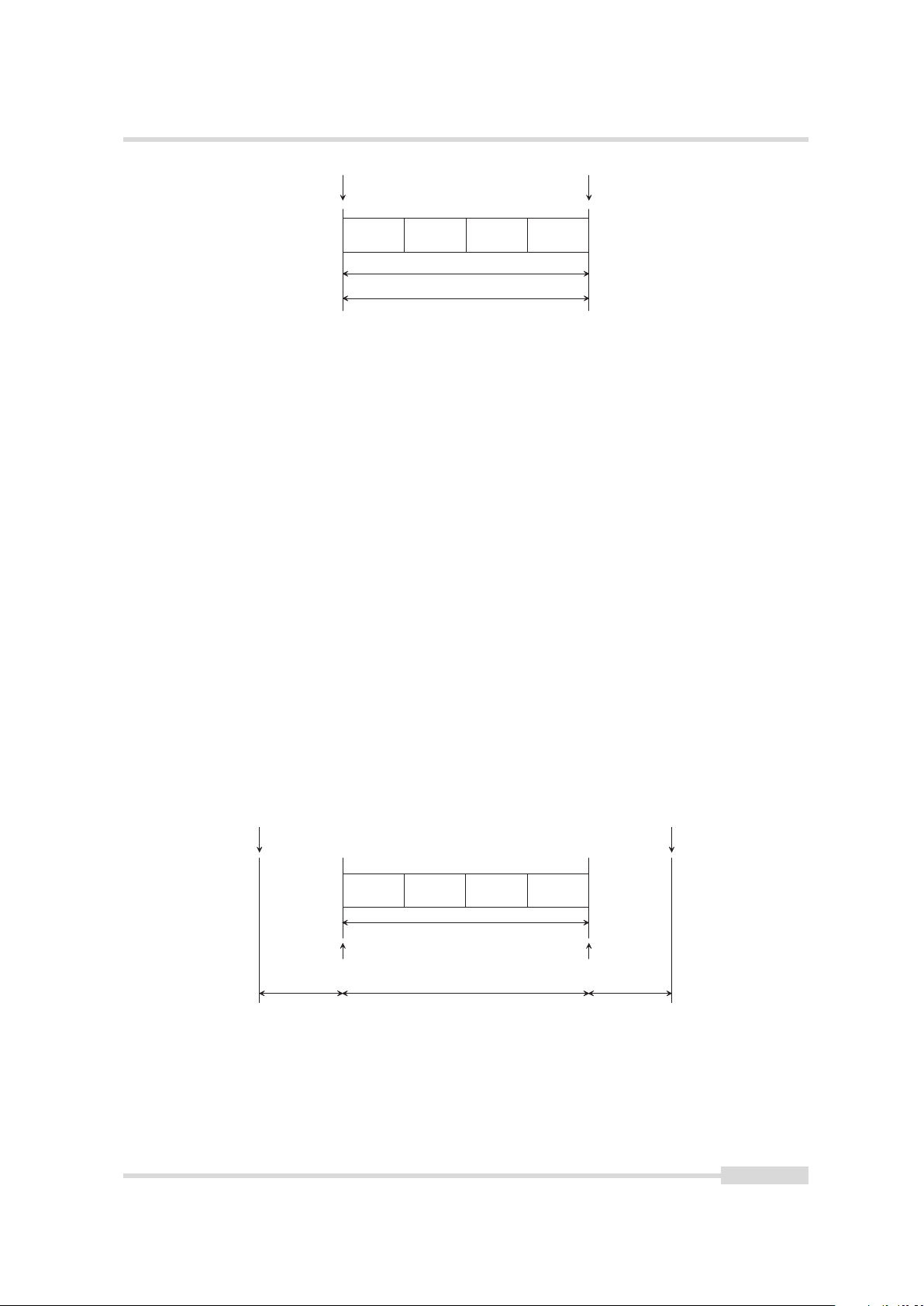
4.5 Overlapped Image Acquisition Timing
The camera is able to perform an overlapped image acquisition. It means, a new exposure can
be started during the image readout of the previous image. Fig. 4.10 shows an image
acquisition procedure when images are captured in overlapped mode. The status "Frame
Active" remains active during the acquisition of the three frames since there is no gap between
two frames. The "Frame Trigger Wait" is asserted during the frame read out in order to
indicate, that a new exposure can be started.
All examples in the previous sections show a non overlapping frame timing. A new frame is
always started after the previous image read out has been finished. All these examples work
also in the overlap mode. It doesn’t show the overlap mode in order to simplify the diagrams.
The overlapped image acquisition is not available, when the triggered controlled
exposure mode is configured.
Figure 4.10: Overlapped Image acquisition Timing
There is a restriction of the overlapped image acquisition: The exposure time of the current
frame must not end prior to the end of the read out of the previous frame. Two different
timing situation needs to be distinguished:
Exposure Time > Read Out Time An new exposure cycle can be started as soon as the read out
Exposure Time < Read Out Time The start of a new exposure has to be delayed by a certain
The camera adjusts the timing automatically, and ensures that it complies with this restriction.
of the previous frame has been started (See Fig. 4.11).
amount of time in order to ensure, that the exposure doesn’t end prior to the image read
out end of the previous frame (See Fig. 4.12).
Frame start or frame burst start triggers which arrive too early and which violates the
overlapping restriction, will be ignored by the camera and indicated by a missed trigger event,
32 of 111 MAN078 12/2018 V1.1

4.5 Overlapped Image Acquisition Timing
E x p o s u r e 1 R e a d O u t 1
F r a m e 1
E x p o s u r e 2 R e a d O u t 2
F r a m e 2
E x p o s u r e 1 R e a d O u t 1
F r a m e 1
E x p o s u r e 2 R e a d O u t 2
F r a m e 2
which can be counted by a counter (see Section 5.1.5 for more information how to count
missed triggers). Fig. 4.11 and Fig. 4.12 shows both timing situations, when the exposure time
longer than the read out time and when the exposure time is shorter than the read out time.
Figure 4.11: Overlapped Image acquisition when exposure time > read out time
Figure 4.12: Overlapped Image acquisition when exposure time < read out time
MAN078 12/2018 V1.1 33 of 111

4 Image Acquisition
E x p o s u r e E n d T r i g g e r
E x p o s u r e S t a r t T r i g g e r
F r a m e B u r s t E n d T r i g g e r
F r a m e B u r s t S t a r t T r i g g e r
F r a m e S t a r t T r i g g e r
A c q u i s i t i o n E n d T r i g g e r
D e l a yD i v i d e r
M o d e
O n
O f f
A c t i v a t i o n
R i s i n g E d g e
F a l l i n g E d g e
B o t h E d g e s
S o u r c e
. . .
S o f t w a r e
A c q u i s i t i o n S t a r t T r i g g e r
4.6 Acquisition-, Frame- and Exposure-Trigger Configuration
The acquisition-, frame- and exposure timing can be controlled by 7 triggers:
• Acquisition Start Trigger
• Acquisition End Trigger
• Frame Start Trigger
• Frame Burst Start Trigger
• Frame Burst End Trigger
• Exposure Start Trigger
• Exposure End Trigger
Fig. 4.13 shows the signal path which is available for every of the 7 triggers. It contains:
• Trigger Source Selection
• Trigger Software
• Trigger Mode
• Trigger Activation
• Trigger Divider
• Trigger Delay
Figure 4.13: Trigger Path
4.6.1 Trigger Source Selection
The user can select the source which is used to generate the corresponding trigger. The source
can come from an external line input, internal pulse generated by a counter or timer or a
pulse, which is generated by software. The following list shows the signal sources, which are
available:
Line In A trigger is generated by a line input signal. The activation configuration defines, if the
Software A trigger is generated by the locally trigger software command register (see Section
34 of 111 MAN078 12/2018 V1.1
rising edge, the falling edge or both edges are taken into account (see Section 4.6.4).
4.6.2 for more information).

4.6 Acquisition-, Frame- and Exposure-Trigger Configuration
Software Signal Pulse A trigger is generated by the software signal pulse, which comes from a
common software signal pulse register (see Section 4.7 for more information).
Counter Start A trigger signal is generated by the counter start event (see Section 5.1.3 for
more information about the counter start event).
Counter End A trigger signal is generated by the counter end event (see Section 5.1.3 for more
information about the counter end event).
Timer Start A trigger signal is generated by the timer start event (see Section 5.2.3 for more
information about the timer start event).
Timer End A trigger signal is generated by the timer end event (see Section 5.2.3 for more
information about the timer end event).
Action A trigger signal is generated by the action control block (see Chapter 7 for more
information about the action control).
4.6.2 Trigger Software
The trigger software is a software command register, which is available in the signal path of
each trigger. Accessing to this register generates an internal trigger, which will be processed in
the signal path.
Trigger source must be set to software in order that a trigger software command
will be processed.
4.6.3 Trigger Mode
The trigger mode defines, if the trigger is active. Following settings are available:
• On
• Off
4.6.4 Trigger Activation
The trigger activation defines, which edge of the selected trigger is processed in the trigger
signal path. Following configuration is available:
• Rising Edge
• Falling Edge
• Both Edges
The trigger activation configuration is only available, when the trigger source is
set to Line In.
MAN078 12/2018 V1.1 35 of 111

4 Image Acquisition
4.6.5 Trigger Divider
The trigger divider specifies a division factor of the incoming trigger pulses. A division factor of
1 processes every incoming trigger. A division factor of 2 processes every second trigger and so
on.
4.6.6 Trigger Delay
The trigger delay lets the user specify a delay, that will be applied between the reception of a
trigger event and when the trigger becomes active.
36 of 111 MAN078 12/2018 V1.1

4.7 Software Signal Pulse and User Output
4.7 Software Signal Pulse and User Output
The software signal pulse block contains eight general purpose registers which allow
generating internal pulse signals by software access. These pulse signals are internally
connected to following functions, where it can be used to start a procedure:
• Acquisition Start Trigger
• Acquisition End Trigger
• Frame Start Trigger
• Frame Burst Start Trigger
• Frame Burst End Trigger
• Exposure Start Trigger
• Exposure End Trigger
• Counter Trigger
• Counter Event
• Counter Reset
• Timer Trigger
The user output block is an eight bit status register. The bits can be set to 0 or 1 by software.
The bits are available in the following firmware blocks/functions:
• Counter Trigger
• Counter Reset
• LED S0, S1 and S2
• Line Out
MAN078 12/2018 V1.1 37 of 111

4 Image Acquisition
38 of 111 MAN078 12/2018 V1.1

Counter & Timer
C o u n t e r
S o u r c e
. . .
A c t i v a t i o n
R i s i n g E d g e
F a l l i n g E d g e
B o t h E d g e s
S o u r c e
. . .
A c t i v a t i o n
R i s i n g E d g e
F a l l i n g E d g e
B o t h E d g e s
S o u r c e
. . .
A c t i v a t i o n
R i s i n g E d g e
F a l l i n g E d g e
B o t h E d g e s
C o u n t e r
T r i g g e r
C o u n t e r
E v e n t
C o u n t e r
R e s e t
T i m e S t a m p
T i c k
C o u n t e r D u r a t i o n
C o u n t e r S t a r t V a l u e
C o u n t e r V a l u e
C o u n t e r S t a t u s
C o u n t e r R e s e t ( )
C o u n t e r V a l u e A t R e s e t
C o u n t e r A c t i v e
C o u n t e r S t a r t
C o u n t e r E n d
5.1 Counter
5
Figure 5.1: Counter Structure
Four general purpose counters are available (Counter0 . . . Counter3) which are used for
counting events. Each counter can be individually configured by software and controlled by
counter trigger, counter event and counter reset signals. This section describes the
configuration and the function of the counters.
Fig. 5.1 shows the structure of one counter. Along with the counter function itself it contains a
counter trigger source, a counter event source and a counter reset source selection and
activation block. Furthermore there is a counter active status signal, which is available in the
I/O control block (see Chapter 6). And the counter generates counter start and counter end
events, which can be used to trigger other blocks, like counter, timer, acquisition, frame or
exposure control.
5.1.1 Counter Usage
In a basic usage, at least a counter event source needs to be selected (see Section 5.1.5 for more
information about the counter event source selection). Once an event source has been
selected, the counter needs to be reset in order to start the counter. When started it counts
from a defined start value, which is configurable by the CounterStartValue property, and ends
counting events after a certain number of events, which is configurable by the
CounterDuration property.
MAN078 12/2018 V1.1 39 of 111

5 Counter & Timer
If additionally a trigger source is selected, the counter is waiting for a trigger. It ignores
counter events until a valid trigger event has been received. A valid trigger signal on the
selected trigger source starts the counter, which means, that it counts the predefined number
of events from the start value according to the counter start value and duration configuration.
The current counter value is readable by the property CounterValue.
5.1.2 Counter Status
The counter has different states, which depends on the configuration and usage. The current
state can be read out by the register CounterStatus. The following list shows the available
states:
Counter Idle Counter is idle, and doesn’t count any events.
Counter Trigger Wait As soon as a counter trigger source is selected (counter trigger source 6=
OFF), the counter goes into the counter trigger wait state and waits for a trigger signal
on the selected source. In this state, the counter does not count any events.
Counter Active Counter is active and is ready to count every event. The counter can be
temporarely stopped by setting the counter event source to OFF .
Counter Completed Counter has stopped as it reached its programmed duration.
Counter Overflow Counter has reached its counter limit, which is 2^32-1, and an additional
counter event signal has been received. Once the counter is in the state overflow, it has
to be reset by software or by counter reset signal in order to recover it from this state.
5.1.3 Counter Active, -Start and -End Signal
Each counter has the following output signals:
Counter Active An asserted counter active signal indicates, that the counter is active and is
counting events. The counter active signal is internally routed to the I/O control block and
can there be selected for output on the physical output line or on one of the available
leds.
Counter Start The counter start is an event, which is generated, when the counter goes into
the counter active state or is restarted during counter active period.
Counter End The counter end is an event, which is generated, when the counter arrives its
configured end condition; and changes to the state counter completed.
The counter start and end event can be used to trigger or to control other function in the
camera, like acquisition, frame and exposure control or counter and timer. It can also be used
to cascade counters in order to get a bigger counting range.
5.1.4 Counter Reset
There are two ways how to reset a counter: Either by a software reset command or by a
hardware reset source signal. The reset behaviour depends on the current counter event and
trigger source configuration:
Counter Trigger Source = Off and Counter Event Source = Off The state of the counter
changes to "idle".
Counter Trigger Source = Off and Counter Event Source 6= Off The state of the counter
changes to "active".
40 of 111 MAN078 12/2018 V1.1

5.1 Counter
Counter Trigger Source 6= Off The state of the counter changes to "trigger wait".
The counter reset source can be set to the counter end signal of the same
counter. This allows to restart the counter automatically as soon as it arrives
its end condition.
The current counter value at the time, when the reset is performed, is stored to the
CounterValueAtReset property, which can be read out by software.
5.1.5 Counter Event Source
The counter event source selects the signal event, which will be the used to increment the
counter. The following signal sources are available:
Off Counter is idle or has been stopped temporarely and doesn’t count any events.
Acquisition Trigger Counts the number of acquisition triggers.
Acquisition Start Counts the number of acquisition start events.
Acquisition End Counts the number of acquisition end events.
FrameTrigger Counts the number of frame triggers.
Frame Start Counts the number of frame start events.
Frame End Counts the number of frame end events.
Frame Burst Start Counts the number of frame burst start events.
Frame Burst End Counts the number of frame burst end events.
Exposure Start Counts the number of exposure start events.
Exposure End Counts the number of exposure end events.
Counter 0 ... 3 Start Counts the number of the chosen counter start events.
Counter 0 ... 3 End Counts the number of the chosen counter end events.
Timer 0 ... 3 Start Counts the number of the chosen timer start events.
Timer 0 ... 3 End Counts the number of the chosen timer end events.
Action 0 ... 3 Counts the number of the chosen action signal events.
Software Signal Pulse 0 ... 7 Counts the number of the chosen software signal pulse events
(see Section 4.7).
Line Input Counts the number of transitions on the line input according to the signal input
activation configuration.
MissedAcqStartTrigger Count the number of missed acquisition start triggers. A missed
acquisition start trigger event is generated, when a acquisition start trigger cannot be
processed.
MissedFrameStartTrigger Count the number of missed frame start triggers. A missed frame
start trigger event is generated, when a frame start trigger cannot be processed.
MAN078 12/2018 V1.1 41 of 111

5 Counter & Timer
MissedFrameBurstStartTrigger Count the number of missed frame burst start triggers. A
missed frame burst start trigger event is generated, when a frame burst start trigger
cannot be processed.
MissedExposureStartTrigger Count the number of missed exposure start triggers. A missed
exposure start trigger event is generated, when an exposure start trigger cannot be
processed.
Missed Trigger Counts the number of any generated missed triggers. The missed trigger is the
logical OR connection of MissedAcqStartTrigger, MissedFrameStartTrigger,
MissedFrameBurstStartTrigger and MissedExposureStartTrigger.
Time Stamp Tick Counts the number of time stamp ticks. A time stamp tick generator is
available for every counter. It generates events with a rate, which can be configured. For
instances if the rate is set to 1 us and the counter event source is set to count time stamp
ticks, the counter increments every 1 us.
Line input source has additionally an activation configuration, which needs to be set
accordingly. Following configuration values are available:
Rising Edge Counter counts rising edges on the selected line input.
Falling Edge Counter counts falling edges on the selected line input
Both Edges Counter counts both edges on the selected line input
Activation configuration has only effect when line input is selected as a counter
event source, otherwise this configuration is ignored.
The counter can be temporarely switched off, if the counter event source is set
to off. It continue counting events as soon as counter event source has been
selected again.
5.1.6 Counter Trigger Source
The counter trigger source selects the signal which will be used to start the counter. The
following signals sources are available:
Off Disables the counter trigger.
Acquisition Trigger Starts with the reception of the acquisition trigger event.
Acquisition Start Starts with the reception of the acquisition start event.
Acquisition End Starts with the reception of the acquisition end event.
FrameTrigger Starts with the reception of the frame trigger event.
Frame Start Starts with the reception of the frame start event.
Frame End Starts with the reception of the frame end event.
Frame Burst Start Starts with the reception of the frame burst start event.
Frame Burst End Starts with the reception of the frame burst end event.
42 of 111 MAN078 12/2018 V1.1

5.1 Counter
Exposure Start Starts with the reception of the exposure start event.
Exposure End Starts with the reception of the exposure end event.
User Output 0 ... 7 Starts and counts events as long as the selected user output bit is asserted.
When the counter is started, it ignores counter events as long as the corresponding user
output bit is deasserted (see Section 4.7).
Counter 0 ... 3 Start Starts with the reception of the chosen counter start event.
Counter 0 ... 3 End Starts with the reception of the chosen counter end event.
Timer 0 ... 3 Start Starts with the reception of the chosen timer start event.
Timer 0 ... 3 End Starts with the reception of the chosen timer end event.
Action 0 ... 3 Starts with the receiption of the chosen action signal event.
Software Signal Pulse 0 ... 7 Starts with the reception of chosen software signal pulse event
(see Section 4.7).
Line Input Starts when the specified counter trigger activation condition is met on the chosen
line.
Line input source has additionally an activation configuration, which needs to be set
accordingly. Following configuration values are available:
Rising Edge Counter starts with the rising edge on the selected line input.
Falling Edge Counter starts with the falling edge on the selected line input.
Both Edges Counter starts with any edge on the selected line input.
Level High Counter starts and is counting events as long as the level is high. When the counter
is started, it ignores counter events as long as the corresponding line input is low.
Level Low Counter starts and is counting events as long as the level is low. When the counter
is started, it ignores counter events as long as the corresponding line input is high.
Activation configuration has only effect when line input is selected as a counter
trigger source, otherwise this configuration is ignored.
5.1.7 Counter Reset Source
The counter reset source selects the signal which will be the used to reset the counter. The
following signals sources are available:
Off Disables the counter reset.
Counter Trigger Resets with the reception of a trigger on the counter trigger source (see
Section 5.1.6).
Acquisition Trigger Resets with the reception of the acquisition trigger.
Acquisition Start Resets with the reception of the acquisition start event.
Acquisition End Resets with the reception of the acquisition end event.
MAN078 12/2018 V1.1 43 of 111

5 Counter & Timer
FrameTrigger Resets with the reception of the frame trigger.
Frame Start Resets with the reception of the frame start event.
Frame End Resets with the reception of the frame end event.
Frame Burst Start Resets with the reception of the frame burst start event.
Frame Burst End Resets with the reception of the frame burst end event.
Exposure Start Resets with the reception of the exposure start event.
Exposure End Resets with the reception of the exposure end event.
User Output 0 ... 7 Resets the counter as long as the selected user output bit is asserted. The
counter remains in reset state until the selected user output bit is deasserted again (see
Section 4.7).
Counter 0 ... 3 Start Resets with the reception of the chosen counter start event.
Counter 0 ... 3 End Resets with the reception of the chosen counter end event.
Timer 0 ... 3 Start Resets with the reception of the chosen timer start event.
Timer 0 ... 3 End Resets with the reception of the chosen timer end event.
Action 0 ... 3 Resets with the reception of the chosen action signal event.
Software Signal Pulse 0 ... 7 Resets with the reception of chosen software signal pulse event
(see Section 4.7).
Line Input Resets when the specified counter trigger activation condition is met on the chosen
line.
Line input source has additionally a activation configuration, which needs to be set
accordingly. Following configuration values are available:
Rising Edge Resets with the rising edge on the selected line input.
Falling Edge Resets with the falling edge on the selected line input.
Both Edges Resets with any edge on the selected line input.
Activation configuration has only effect when line input is selected as a counter
reset source, otherwise this configuration is ignored.
5.2 Timer
Four general purpose timers are available in the camera (Timer0 ... Timer3). A timer can be
used to generate a timed pulse - for instances a strobe signal - or to generate an event after a
predetermined duration. Each timer can be configured individually by software and controlled
by timer trigger events. This section describes the configuration and the function of the timers.
Fig. 5.2 shows the structure of one timer. It contains a timer trigger source and activation
block. Furthermore it has three output signals: A timer active status signal, which is routed to
the I/O control block (see Chapter 6) and timer start and end event signals, which can be used
to trigger other blocks, like counter, timer, acquisition, frame or exposure control (see Section
5.2.3).
44 of 111 MAN078 12/2018 V1.1

5.2 Timer
T i m e r
S o u r c e
. . .
T i m e r
T r i g g e r
T i m e r A c t i v e
T i m e r S t a r t
T i m e r E n d
T i m e r V a l u e
T i m e r S t a t u s
T i m e r D e l a y
T i m e r S t a r t V a l u e
T i m e r D u r a t i o n
T i m e r R e s e t ( )
A c t i v a t i o n
R i s i n g E d g e
F a l l i n g E d g e
B o t h E d g e s
Figure 5.2: Timer Structure
5.2.1 Timer Usage
Timer delay and timer duration value needs to be configured accordingly. When a timer trigger
source is selected the timer is waiting for a trigger signal. Once this trigger signal has been
received, the timer starts first with the timer delay period, if the timer delay value is > 0, and
counts then for the specified timer duration.
When the timer trigger source is set to off (see Section 5.2.5), a software timer
reset command starts the timer immediately (see Section 5.2.4).
The current timer value can be read via software. A start value can also be set, which means,
that the timer starts from this configured value instead from zero.
5.2.2 Timer Status
The timer has different states, which depends on the configuration and usage. The current
state can be read out by the register TimerStatus. The following list shows the available states:
Timer Idle Timer is idle, and trigger source selection is set to off.
Timer Trigger Wait Timer is waiting for a timer trigger signal.
Timer Delay Timer is in timer delay count period.
Timer Active Time is active and counts for the specified timer duration.
Timer Completed Timer completed indicates, that the timer reached the timer duration count.
The timer remains in this state, until a new timer trigger event has been received, or the
timer is reset by a software command (see Section 5.2.4)
5.2.3 Timer Active, -Start and -End Signal
Timer Active An asserted timer active signal indicates, that the timer has started counting the
configured duration period. The timer active signal is internally routed to the I/O control
block and can there be selected for output on the physical output line or on one of the
available leds.
Timer Start The timer start is an event, which is generated, when the timer starts with the
timer duration period.
Timer End The timer end is an event, which is generated, when the timer arrives its configured
timer duration value.
The timer start and end event signals can be used to trigger other blocks, like counter, timer,
acquisition, frame or exposure control.
MAN078 12/2018 V1.1 45 of 111

5 Counter & Timer
5.2.4 Timer Reset
The timer can be reset by a software command. It performs a software reset of the timer
counter and starts the timer immediately (change to state timer active), when trigger source is
set to off; otherwise it goes into the state timer trigger wait.
5.2.5 Timer Trigger Source
The timer trigger source selects the events that will be the used to reset and to start the timer.
The following list of signals are available:
Off Disables the timer trigger.
Acquisition Trigger Starts with the reception of the acquisition trigger event.
Acquisition Start Starts with the reception of the acquisition start event.
Acquisition End Starts with the reception of the acquisition end event.
FrameTrigger Starts with the reception of the frame trigger event.
Frame Start Starts with the reception of the frame start event.
Frame End Starts with the reception of the frame end event.
Frame Burst Start Starts with the reception of the frame burst start event.
Frame Burst End Starts with the reception of the frame burst end event.
Exposure Start Starts with the reception of the exposure start event.
Exposure End Starts with the reception of the exposure end event.
User Output 0 ... 7 Starts when the selected user output bit is set to 1.
Counter 0 ... 3 Start Starts with the reception of the chosen counter start event.
Counter 0 ... 3 End Starts with the reception of the chosen counter end event.
Timer 0 ... 3 Start Starts with the reception of the chosen timer start event.
Timer 0 ... 3 End Starts with the reception of the chosen timer end event.
Action 0 ... 3 Starts with the reception of the chosen action signal event.
Software Signal Pulse 0 ... 7 Starts with the reception of chosen software signal pulse event
(see Section 4.7).
Line Input Starts when the specified counter trigger activation condition is met on the chosen
line.
Line input source has additionally a activation configuration, which needs to be set
accordingly. Following configuration values are available:
Rising Edge Timer starts with the rising edge on the selected line input.
Falling Edge Timer starts with the falling edge on the selected line input.
Both Edges Timer starts with any edge on the selected line input.
A self re-trigger timer can be configured, when the trigger source is set to its
own timer end event. The timer needs a software reset in order to start the self
re-trigger mode.
46 of 111 MAN078 12/2018 V1.1

6
I n p u t S i g n a l P a t h
S t a t u s
I n v e r t
L i n e I n
I/O Control
This chapter shows the structure of the physical input and physical output line. It describes the
signal path and how to configure it.
The I/O control block contains a signal input path and a signal output path.
6.1 Input Signal Path
The camera has one physical signal input line, which comes from the input opto-isolator of the
camera hardware interface (see Section 13.6) and which is fed into the input signal path of the
camera. Fig. 6.1 shows the structure of the input signal path. The user can invert this signal
and its current status can be read by software.
Figure 6.1: Input Signal Path
The output of the signal input path is distributed to following camera function:
• Acquisition Start Trigger
• Acquisition End Trigger
• Frame Start Trigger
• Frame Burst Start Trigger
• Frame Burst End Trigger
• Exposure Start Trigger
• Exposure End Trigger
• Counter Trigger
• Counter Event
• Counter Reset
• Timer Trigger
• Line Out
• LED S0, S1 or S2
6.2 Output Signal Path
The camera has one physical signal output line and three LEDs (S0, S1 & S2), which can be
configured according to the need of the application. The physical output line is connected to
the output opto-isolator in the camera hardware interface (see Section 13.6). The output line,
LED0, LED1 and LED2 have its own output signal path which is shown in Fig. 6.2. The source
can be selected and the selected signal can be inverted before it is sent out of the camera.
Furthermore the current status of the output signal can read by software.
Following signals are available and can be selected for the output:
MAN078 12/2018 V1.1 47 of 111

6 I/O Control
O u t p u t S i g n a l P a t h " L E D S 0 "
O u t p u t S i g n a l P a t h " L E D S 1 "
O u t p u t S i g n a l P a t h " L E D S 2 "
O u t p u t S i g n a l P a t h " L i n e O u t "
S t a t u s
I n v e r t
S o u r c e
. . .
L E D S 0
L E D S 1
L E D S 2
L i n e O u t
Figure 6.2: Output Signal Path
• Input Line
• Counter Active Status
• Timer Active Status
• User Output
• Acquisition Trigger Wait Status
• Acquisition Active Status
• Frame Trigger Wait Status
• Frame Active Status
• Exposure Active Status
• Frame Valid Status
• Line Valid Status
• Heartbeat
• Serial Communication
• Constant 0 Value
• Constant 1 Value
If the source heartbeat is selected, the led shows a pulsating behaviour, when the camera is
idle (no image capturing is active). It means, the intensity starts from dark and goes slowly to
bright and slowly to dark again. Every time, when the camera is acquiring and sending images,
the LED changes to a blinking characteristic.
If the source serial communication is selected, the led flashes every time when the host
communicates with the camera, due to changing or reading of camera parameters.
48 of 111 MAN078 12/2018 V1.1

7
A c t i o n C o n t r o l
A c t i o n D e v i c e K e y
A c t i o n G r o u p M a s k
A c t i o n G r o u p K e y
A c t i o n 3
A c t i o n 3
A c t i o n G r o u p M a s k
A c t i o n G r o u p K e y
A c t i o n 2
A c t i o n 2
A c t i o n G r o u p M a s k
A c t i o n G r o u p K e y
A c t i o n 1
A c t i o n 1
A c t i o n G r o u p M a s k
A c t i o n G r o u p K e y
A c t i o n 0
A c t i o n 0
A c t i o n U n c o n d i t i o n a l M o d e
Action Control
Figure 7.1: Action Control Structure
Action signals are a method to send triggers to multiple cameras in a common network at the
same time. Four action signals are available in the Photonfocus GigE cameras. Each of them
can be used as a trigger for the image acquisition, counter and/or timer. The commands are
sent via the transport layer as a broadcast protocol message. The configuration parameters
ActionDeviceKey, ActionGroupKey and ActionGroupMask in the camera allow filtering of these
broadcast messages: The corresponding action signal is only asserted, when the received
broadcast message matches to its key and mask configuration.
The action command enables triggering of the camera with low latency and low jitter.
7.1 Action Command Usage
Each action command message comes with the following key and mask information, which is
necessary to validate the requested action signal:
ActionUnconditionalMode Enables the unconditional action command mode where action
ActionDeviceKey The ActionDeviceKey authorize the action in the camera. The camera reacts
ActionGroupKey The ActionGroupKey defines a group of devices on which the action has to be
ActionGroupMask The ActionGroupMask filters out some of the devices of the group, which
The corresponding action signal is only asserted if:
• the configured ActionDeviceKey is equal to the action device key in the message.
• the configured ActionGroupKey is equal to the action group key in the message.
• the logical AND-wise operation of the action group mask in the message against the
MAN078 12/2018 V1.1 49 of 111
commands are processed even when the primary control channel is closed.
only, when the received action message includes the correct action device key value. In
the camera ActionDeviceKey value is configured once and applied globally to all four
action signals..
executed. This enables an action command to be applied to a specific subset of devices.
Each action signal has its own group key, which need to be defined in the camera.
are selected by the action group key. Each action signal has its own group mask, which
need to be defined in the camera.
selected ActionGroupMask is non-zero.

7 Action Control
7.2 Action Control Output
The action output signals can be used to trigger other blocks, like counter, timer, acquisition,
frame or exposure control.
50 of 111 MAN078 12/2018 V1.1

8
Image Format Control
The focus on the interesting parts of an image can be set by setting the region of interest (ROI)
(see Section 8.1).
The ROI influences the image size which leads into an increased frame rate (see Chapter 9 for
more information about the available frame rate).
8.1 Region of Interest (ROI)
Some applications do not need full image resolution. The image size can be reduced by setting
the horizontal image offset (Offset X) and the image width (Width) and by setting the vertical
image offset (OffsetY) and image height (Height). A region of interest can be almost any
rectangular window but it must be placed within the sensor area. OffsetX + Width must not
exceed the sensor width and OffsetY + Height must not exceed sensor height.
The ROI OffsetX and Width must be a multiple of 8 in the D2048x1088-C01 and
the D2048-C01 cameras.
MAN078 12/2018 V1.1 51 of 111

8 Image Format Control
52 of 111 MAN078 12/2018 V1.1

9
Frame Rate
The frame rate depends on the image size, the used exposure time and the max data rate of
the GigE interface (MaxDataRateInterface). The image size is given by the image size, which
can be configured by the ROI, MROI and decimation settings (see Chapter 8).
Two different timing situations has to be considered:
• Exposure time is dominant
• Image size is dominant
Depending on the timing situation the frame rate is calculated according to the formula in
Section 9.1 or in Section 9.2. In order to find out what is dominant, both timing situation needs
to be calculated and the lower value defines the maximum frame rate.
9.1 Exposure time is dominant
The frame rate is given by the configured exposure time. The maximal frame rate is in this
case:
FrameRate = (1 / (ExposureTime + FramePause))
FramePause is 40...85 µs
9.2 Image size is dominant
The fame rate is given by the configured image size. The maximal frame rate is in this case is
given by the max data rate of the GigE interface:
FrameRate = MaxDataRateInterface / (WidthMax x HeightMax x [Bits per Pixel])
Bits per pixel depends on the PixelFormat settings:
Mono8 8 bit per pixel
Mono10 16 bit per pixel
Mono10Packed 12 bit per pixel
Mono12 16 bit per pixel
Mono10Packed 12 bit per pixel
9.3 Maximum Frame Rate
A list of common used image dimension and its frame rates is shown in Table 9.1. It shows the
maximum possible frame rates when the exposure time is smaller than the read out time.
There is a frame rate calculator in the support section of the Photonfocus web
page www.photonfocus.com, which allows to determine the frame rates for any
available image dimensions and expsoure time settings.
MAN078 12/2018 V1.1 53 of 111

9 Frame Rate
ROI Dimension [Standard] D2048x1088-C01 (CMV2000) D2048-C01 (CMV4000)
2048 x 2048 n.a. 26 fps
2048 x 1088 50 fps 50 fps
1920 x 1080 (HD1080) 54 fps 54 fps
1280 x 1024 (SXGA) 75 fps 75 fps
1024 x 1024 106 fps 106 fps
1280 x 768 (WXGA) 100 fps 100 fps
800 x 600 (SVGA) 233 fps 233 fps
640 x 640 240 fps 240 fps
640 x 480 (VGA) 318 fps 318 fps
480 x 480 486 fps 486 fps
Table 9.1: Frame rates of different ROI settings (minimal exposure time).
54 of 111 MAN078 12/2018 V1.1

10
High Dynamic Range Mode (HDR)
10.1 Multiple Slope Mode (High Dynamic Range)
The Multiple Slope High Dynamic Range (HDR) mode is a special integration mode that
increases the dynamic range of the pixels, and thus avoids the saturation of the pixels in many
cases. The multiple slope mode is also called multiple slope mode or piecewise linear mode.
The multiple slope mode clips illuminated pixels which reach a programmable voltage, while
leaving the darker pixels untouched (see Fig. 10.1). The clipping level can be adjusted once (2
slopes) or twice (3 slopes) within the exposure time.
Parameters:
Multislope_Mode There are 3 predefined multiple slope parameter sets: LowCompression,
NormalCompression and HighCompression. If Multislope_Mode is set to UserDefined then the
individual parameters can be set to user defined values.
Multislope_NrSlopes Number of slopes. Multislope_NrSlopes=2: 2 slopes with only kneepoint B.
Multislope_NrSlopes=3: 3 slopes with kneepoints A and B.
Multislope_Value1 Corresponds to Vlow1: the higher the value, the higher the compression.
Multislope_Time1 Time corresponding to kneepoint B. The value is the fraction (per mill) of
the total exposure time.
Multislope_Value2 Corresponds to Vlow2: the higher the value, the higher the compression.
This value is ignored if Multislope_NrSlopes =2.
Multislope_Time2 Time corresponding to kneepoint A. The value is the fraction (per mill) of
the total exposure time. This value is ignored if Multislope_NrSlopes =2.
The red line in Fig. 10.1 shows a pixel with high illumination. Without the multiple slope
mode, the pixel would have reached its saturated value. With multiple slope mode, the pixel
reaches value P1 which is below the saturation value. The resulting pixel response in this case is
shown in Fig. 10.2. The blue line (P2) shows a pixel with low illumination. Its value never
reaches Vlow2 or Vlow1 at the kneepoints and the resulting response is linear.
The parameters Multislope_Value1 and Multislope_Value2 are only applied after
a camera trigger. Note that in free-running mode the camera trigger is applied
internally by the camera itself.
MAN078 12/2018 V1.1 55 of 111

10 High Dynamic Range Mode (HDR)
t i m e
V h i g h
V l o w 2 ( M u l t i s l o p e _ V a l u e 2 )
V l o w 1 ( M u l t i s l o p e _ V a l u e 1 )
P 1
P 2
P i x e l r e s e t
K n e e p o i n t A
K n e e p o i n t B
M u l t i s l o p e _ T i m e 2
M u l t i s l o p e _ T i m e 1
E x p o s u r e T i m e
n u m b e r o f e l e c t r o n s
S a t u r a t i o n l e v e l
O u t p u t s i g n a l
K n e e p o i n t A
K n e e p o i n t B
Figure 10.1: Multi Slope Mode
Figure 10.2: Piecewise linear response
56 of 111 MAN078 12/2018 V1.1

11
Image Data Processing
11.1 Overview
The pixel, which are read out of the image sensor, are processed in the cameras data path. The
sequence of blocks is shown in figure Fig. 11.1.
.
MAN078 12/2018 V1.1 57 of 111

11 Image Data Processing
I m a g e S e n s o r
D i g i t a l O f f s e t
D i g i t a l G a i n
L o o k - u p t a b l e ( L U T )
C r o s s h a i r s i n s e r t i o n
S t a t u s l i n e i n s e r t i o n
T e s t i m a g e s i n s e r t i o n
I m a g e o u t p u t
D i g i t a l F i n e G a i n
C o l u m n F P N
C o r r e c t i o n
R G B C o l o u r
C h a n n e l G a i n
Figure 11.1: Camera data path
58 of 111 MAN078 12/2018 V1.1

11.2 Column FPN Correction
11.2 Column FPN Correction
Due to the readout structure of the image sensors there is a column-wise fixed pattern noise
(FPN). The Column FPN Correction (ColCorrection) adds or subtracts a fixed value to a column.
These values are obtained by a calibration process. The ColCorrection of the camera was
calibrated at Photonfocus production facility.
11.2.1 Enable / Disable the Column FPN Correction
The Column FPN Correction can be enabled or disabled with the property ColCorrection_Enable
(in category Photonfocus/ColCorrection). By default the correction is enabled.
11.2.2 Calibration of the Column FPN Correction
The Column FPN Correction of the camera is correctly calibrated at Photonfocus production
facility. Although a new calibration is normally not required, you can recalibrate the Column
FPN Correction with the following instructions:
1. Setup the camera to the mode where it will be usually used. (Exposure time, ...). The
width and height should be set to its maximal value.
If different exposure times will be used, calibrate the camera under the longest
exposure time.
2. Start the aqcuisition of the camera.
3. Close the lens of the camera or put a cap on the lens. The calibration requires an uniform
dark image. The black level offset should be set so that all pixels (except defect pixels)
have values above 0.
4. Run the command ColCorrection_CalibrateBlack (category ColCorrection) by clicking on
the corresponding button.
The calibration process needs some images in order to do the calibration. If the
camera is in triggered mode, the user must apply the corresponding triggers.
To get the best calibration results, the camera should have achieved the working
temperatur.
5. Run the command ColCorrection_Update by clicking on the corresponding button. Read the
ColCorrection_Busy value which should be 0 after the calibration has finished. Repeat this
step if its value is not 0. If the ColCorrection_Busy value doesn’t show 0 after various tries,
check if the camera receive triggers, when the triggered mode is activated.
6. Check the values of the properties ColCorrection_Overflow and ColCorrection_Underflow. Both
should have the value 0 after calibration. If ColCorrection_Overflow is not 0, then decrease
BlackLevel (in category AnalogControl) and re-run the procedure from step 4 on. If
ColCorrection_Underflow is not 0, then increase BlackLevel (in category AnalogControl) and
re-run the procedure from step 4 on.
7. The Column FPN correction is now calibrated. The calibration values are stored in the
camera’s RAM and these values are lost when the camera power is turned off. To store the
calibration values to permanent memory see Section 11.2.3.
MAN078 12/2018 V1.1 59 of 111

11 Image Data Processing
Column noise changes with different analog gain settings. The column FPN correction of the camera needs to be recalibrated when the analog gain setting is
changed.
11.2.3 Storing the calibration in permanent memory
After running the calibration procedure (see Section 11.2.2) the calibration values are stored in
RAM. When the camera is turned off, their values are lost.
To prevent this, the calibration values must be stored in flash memory. This can be done by
clicking on the property ColCorrection_SaveToFlash (in category ColCorrection). Wait until the
command has been finished, i.e.the property ColCorrection_Busy (category Correction /
ColCorrection) is 0. ColCorrection_Busy can be updated by clicking on the property
ColCorrection_Update (in category Calibration).
Storing the calibration in permanent memory overwrites the factory calibration.
11.3 Gain and Offset
There are three different gain settings on the camera:
Analog Gain Analog gain on the image sensor. Available values: x1, x1.6, x2.0, x2.6, x3.2 and
x4.0. Note that Digital Offset is applied after the Analog Gain.
Gain (Digital Fine Gain) Digital fine gain accepts fractional values from 0.01 up to 15.99. It is
implemented as a multiplication operation. Colour camera models only: There is
additionally a gain for every RGB colour channel. The RGB channel gain is used to
calibrate the white balance in an image, which has to be set according to the current
lighting condition.
Digital Gain Digital Gain is a coarse gain with the settings x1, x2, x4 and x8. It is implemented
as a binary shift of the image data where ’0’ is shifted to the LSB’s of the gray values. E.g.
for gain x2, the output value is shifted by 1 and bit 0 is set to ’0’.
The resulting gain is the product of the three gain values, which means that the image data is
multiplied in the camera by this factor.
Digital Fine Gain and Digital Gain may result in missing codes in the output image data.
A user-defined value can be subtracted from the gray value in the digital offset block. If digital
gain is applied and if the brightness of the image is too big then the interesting part of the
output image might be saturated. By subtracting an offset from the input of the gain block it
is possible to avoid the saturation.
60 of 111 MAN078 12/2018 V1.1

11.4 Grey Level Transformation (LUT)
a
y = f ( x )
x
x
m a x
x
0
x
1
y
m a x
b
c
d
11.4 Grey Level Transformation (LUT)
Grey level transformation is remapping of the grey level values of an input image to new
values. The look-up table (LUT) is used to convert the greyscale value of each pixel in an image
into another grey value. It is typically used to implement a transfer curve for contrast
expansion. The camera performs a 12-to-8-bit mapping, so that 4096 input grey levels can be
mapped to 256 output grey levels. The use of the three available modes is explained in the next
sections. Two LUT and a Region-LUT feature are available in the camera (see Section 11.4.4).
The LUT is implemented as a 12-to-8 bit LUT to be compatible with other Photonfocus cameras. Bits 0 & 1 of the 12 bit LUT input data are set to random
values.
The output grey level resolution of the look-up table (independent of gain,
gamma or user-definded mode) is always 8 bit.
There are 2 predefined functions, which generate a look-up table and transfer it
to the camera. For other transfer functions the user can define his own LUT file.
Some commonly used transfer curves are shown in Fig. 11.2. Line a denotes a negative or
inverse transformation, line b enhances the image contrast between grey values x0 and x1.
Line c shows brightness thresholding and the result is an image with only black and white grey
levels. and line d applies a gamma correction (see also Section 11.4.2).
Figure 11.2: Commonly used LUT transfer curves
11.4.1 Gain
The ’Gain’ mode performs a digital, linear amplification with clamping (see Fig. 11.3). It is
configurable in the range from 1.0 to 4.0 (e.g. 1.234).
MAN078 12/2018 V1.1 61 of 111
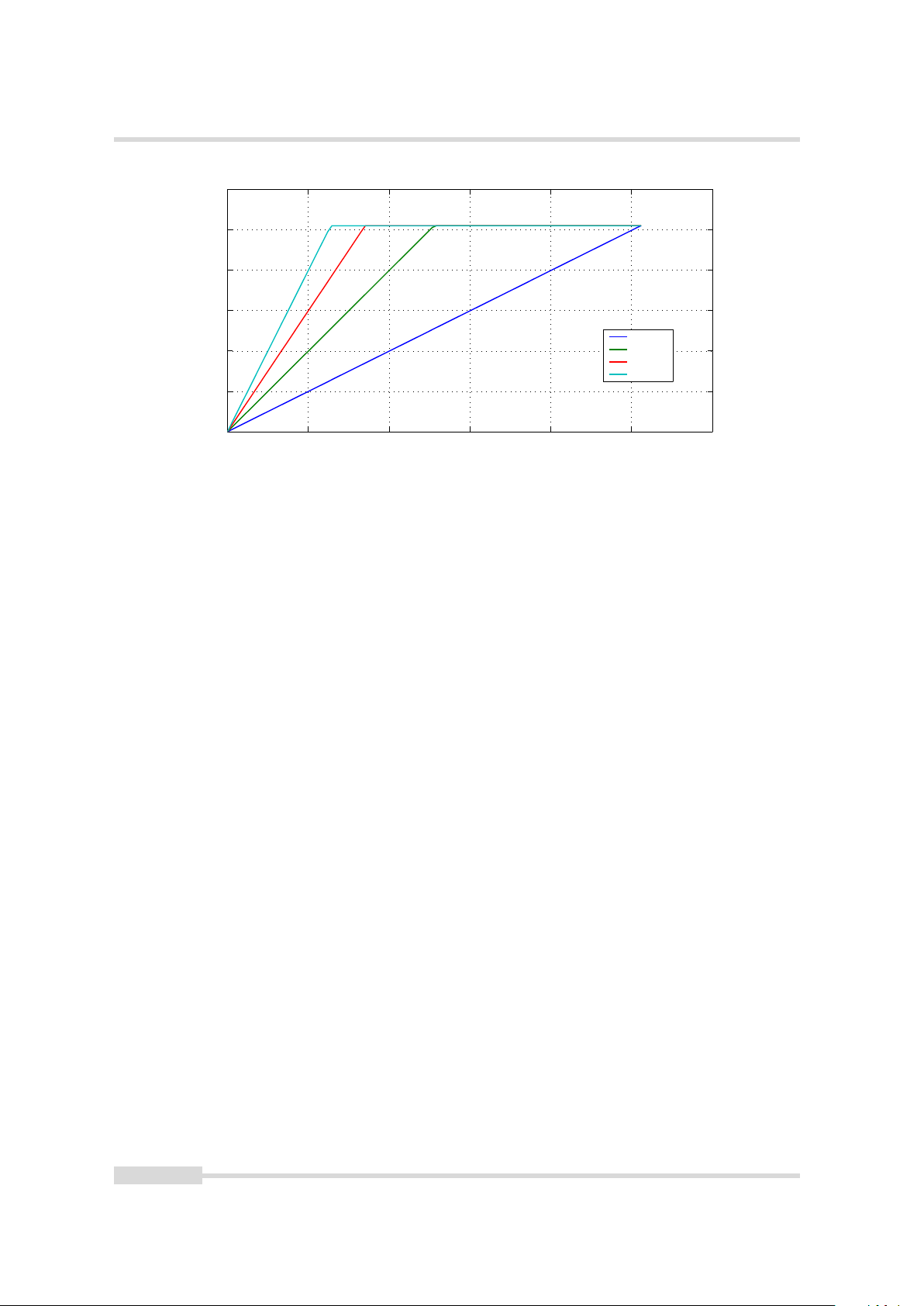
11 Image Data Processing
0 200 400 600 800 1000 1200
0
50
100
150
200
250
300
Grey level transformation − Gain: y = (255/1023) ⋅ a ⋅ x
x: grey level input value (10 bit) [DN]
y: grey level output value (8 bit) [DN]
a = 1.0
a = 2.0
a = 3.0
a = 4.0
Figure 11.3: Applying a linear gain with clamping to an image
62 of 111 MAN078 12/2018 V1.1

11.4 Grey Level Transformation (LUT)
0 200 400 600 800 1000 1200
0
50
100
150
200
250
300
Grey level transformation − Gamma: y = (255 / 1023γ) ⋅ xγ (γ ≥ 1)
x: grey level input value (10 bit) [DN]
y: grey level output value (8 bit) [DN]
γ = 1.0
γ = 1.2
γ = 1.5
γ = 1.8
γ = 2.5
γ = 4.0
0 200 400 600 800 1000 1200
0
50
100
150
200
250
300
Grey level transformation − Gamma: y = (255 / 1023γ) ⋅ xγ (γ ≤ 1)
x: grey level input value (10 bit) [DN]
y: grey level output value (8 bit) [DN]
γ = 1.0
γ = 0.9
γ = 0.8
γ = 0.6
γ = 0.4
11.4.2 Gamma
The ’Gamma’ mode performs an exponential amplification, configurable in the range from 0.4
to 4.0. Gamma > 1.0 results in an attenuation of the image (see Fig. 11.4), gamma < 1.0 results
in an amplification (see Fig. 11.5). Gamma correction is often used for tone mapping and
better display of results on monitor screens.
Figure 11.4: Applying gamma correction to an image (gamma > 1)
Figure 11.5: Applying gamma correction to an image (gamma < 1)
MAN078 12/2018 V1.1 63 of 111

11 Image Data Processing
U s e r L U T
y = f ( x )
1 2 b i t
8 b i t
11.4.3 User-defined Look-up Table
In the ’User’ mode, the mapping of input to output grey levels can be configured arbitrarily by
the user. This procedure is explained in Section C.4.
Figure 11.6: Data path through LUT
11.4.4 Region LUT and LUT Enable
Two LUTs and a Region-LUT feature are available in the camera. Both LUTs can be enabled
independently (see Table 11.1). LUT 0 superseeds LUT1.
Enable LUT 0 Enable LUT 1 Enable Region LUT Description
- - - LUT are disabled.
X don’t care - LUT 0 is active on whole image.
- X - LUT 1 is active on whole image.
X - X LUT 0 active in Region 0.
X X X LUT 0 active in Region 0 and LUT 1 active
in Region 1. LUT 0 supersedes LUT1.
Table 11.1: LUT Enable and Region LUT
When Region-LUT feature is enabled, then the LUTs are only active in a user defined region.
Examples are shown in Fig. 11.7 and Fig. 11.8.
Fig. 11.7 shows an example of overlapping Region-LUTs. LUT 0, LUT 1 and Region LUT are
enabled. LUT 0 is active in region 0 ((x00, x01), (y00, y01)) and it supersedes LUT 1 in the
overlapping region. LUT 1 is active in region 1 ((x10, x11), (y10, y11)).
Fig. 11.8 shows an example of keyhole inspection in a laser welding application. LUT 0 and LUT
1 are used to enhance the contrast by applying optimized transfer curves to the individual
regions. LUT 0 is used for keyhole inspection. LUT 1 is optimized for seam finding.
.
64 of 111 MAN078 12/2018 V1.1

L U T 0
( 0 , 0 )
( x
m a x
, y
m a x
)
L U T 1
x 0 0 x 1 0 x 0 1 x 1 1
y 1 0
y 0 0
y 0 1
y 1 1
Figure 11.7: Overlapping Region-LUT example
L U T 0
L U T 1
L U T 1
L U T 0
( 0 , 0 )
( 0 , 0 )
( x
m a x
, y
m a x
)
( x
m a x
, y
m a x
)
11.4 Grey Level Transformation (LUT)
Figure 11.8: Region-LUT in keyhole inspection
MAN078 12/2018 V1.1 65 of 111

11 Image Data Processing
Fig. 11.9 shows the application of the Region-LUT to a camera image. The original image
without image processing is shown on the left-hand side. The result of the application of the
Region-LUT is shown on the right-hand side. One Region-LUT was applied on a small region on
the lower part of the image where the brightness has been increased.
Figure 11.9: Region-LUT example with camera image; left: original image; right: gain 4 region in the are
of the date print of the bottle
.
66 of 111 MAN078 12/2018 V1.1

11.5 Crosshairs
11.5 Crosshairs
The crosshairs inserts a vertical and horizontal line into the image. The width of these lines is
one pixel. The grey level is defined by a 12 bit value (0 means black, 4095 means white). This
allows to set any grey level to get the maximum contrast depending on the acquired image.
The x/y position and the grey level can be set via the camera software. Figure Fig. 11.10 shows
two examples of the activated crosshairs with different grey values. One with white lines and
the other with black lines.
The 12-bit format of the grey level was chosen to be compatible with other
Photonfocus cameras.
Figure 11.10: Crosshairs Example with different grey values
MAN078 12/2018 V1.1 67 of 111

11 Image Data Processing
( 0 , 0 )
( x
a b s o l u t
, y
a b s o l u t
, G r e y L e v e l )
R O I
( 0 , 0 )
( x
m a x
, y
m a x
)
R O I
( x
a b s o l u t
, y
a b s o l u t
, G r e y L e v e l )
R O IR O I
( x
m a x
, y
m a x
)
The x- and y-positon is absolute to the sensor pixel matrix. It is independent on the image
format settings (see Chapter 8 for more information about the available image format
configurations).
Fig. 11.11 shows two situations of the crosshairs configuration. The same image format
settings are used in both situations. The crosshairs however is set differently. The crosshairs is
not seen in the image on the right, because the x- and y-position is set outside the ROI region.
Figure 11.11: Crosshairs absolute position
.
68 of 111 MAN078 12/2018 V1.1

11.6 Status Line and Image Information
4 8 1 2 1 6 2 0
P r e a m b l e
F i e l d 0
0P i x e l :
1 2 3 5 6 7 9 1 0 1 1 1 3 1 4 1 5 1 7 1 8 1 9 2 1 2 2 2 3
L S B
M S B
6 6 B B 0 0 F F
F i e l d 1 F i e l d 2 F i e l d 3 F i e l d 4
L S B L S B L S B L S B L S B
M S B M S B M S B M S B M S B
11.6 Status Line and Image Information
There are camera properties available that give information about the acquired images, such
as integration time, ROI settings or average image value. These properties can be queried by
software. Alternatively, a status line within the image data can be switched on that contains all
the available image information.
11.6.1 Image Average Value
The average image value gives the average of an image in 12 bit format (0 .. 4095 DN),
regardless of the currently used grey level resolution. Note that the 12-bit format was chosen
to be compatible with other Photonfocus cameras
11.6.2 Status Line Format
If enabled, the status line replaces the last row of the image with camera status information.
Every parameter is coded into fields of 4 pixels (LSB first) and uses the lower 8 bits of the pixel
value, so that the total size of a parameter field is 32 bit (see Fig. 11.12). The assignment of the
parameters to the fields is listed in Table 11.2.
The status line is available in all camera modes.
Figure 11.12: Status line parameters replace the last row of the image
.
MAN078 12/2018 V1.1 69 of 111

11 Image Data Processing
Start pixel index Parameter width [bit] Parameter Description
0 32 Preamble: 0x66BB00FF
4 32 Counter 0 Value (see Section 5.1)
8 32 Counter 1 Value (see Section 5.1)
12 32 Counter 2 Value (see Section 5.1)
16 32 Counter 3 Value (see Section 5.1)
20 32 Timer 0 Value in units of clock cycles (see Section
5.2)
24 32 Timer 1 Value in units of clock cycles (see Section
5.2)
28 32 Timer 2 Value in units of clock cycles (see Section
5.2)
32 32 Timer 3 Value in units of clock cycles (see Section
5.2)
36 24 Integration Time 1 in units of clock cycles
40 24 Integration Time 2 in units of clock cycles
44 32 Timer and Integration Time Clock Frequency
48 12 Image Average Value("raw" data without taking
in account gain settings) (see Section 11.6.1)
52 12 Horizontal start position of ROI (OffsetX)
56 12 Image Width
60 12 Vertical start position of ROI (OffsetY).
64 12 Image Height
68 2 Digital Gain
72 12 Digital Offset
76 16 FineGain. This is fixed a point value in the
format: 4 digits integer value, 12 digits
fractional value.
80 1 Line Input Level
84 16 Camera Type Code (see Table 11.3)
88 32 Camera Serial Number
92 32 Custom value 0: value of register
StatusLineCustomValue0 that can be set by the
user
96 32 Custom value 1: value of register
StatusLineCustomValue1 that can be set by the
user
Table 11.2: Assignment of status line fields
70 of 111 MAN078 12/2018 V1.1

11.6.3 Camera Type Codes
Camera Model Camera Type Code
MV0-D2048x1088-C01-160-G2 504
MV0-D2048-C01-160-G2 505
Table 11.3: Type codes of Photonfocus MV0 CMOSIS GigE camera series
11.6 Status Line and Image Information
.
MAN078 12/2018 V1.1 71 of 111

11 Image Data Processing
11.7 Test Images
Test images are generated in the camera FPGA, independent of the image sensor. They can be
used to check the transmission path from the camera to the acquisition software. Independent
from the configured grey level resolution, every possible grey level appears the same number
of times in a test image. Therefore, the histogram of the received image must be flat.
A test image is a useful tool to find data transmission errors or errors in the access
of the image buffers by the acquisition software.
The analysis of the test images with a histogram tool gives gives a flat histogram
only if the image width is a multiple of 1024 (in 10 bit mode) or 256 (in 8 bit
mode).
11.7.1 Ramp
Depending on the configured grey level resolution, the ramp test image outputs a constant
pattern with increasing grey level from the left to the right side (see Fig. 11.13).
Figure 11.13: Ramp test images: 8 bit output (left), 10 bit output (right)
11.7.2 LFSR
The LFSR (Linear Feedback Shift Register) test image outputs a constant pattern with a
pseudo-random grey level sequence containing every possible grey level that is repeated for
every row. The LFSR test pattern was chosen because it leads to a very high data toggling rate,
which stresses the interface electronic and the cable connection.
In the histogram you can see that the number of pixels of all grey values are the same.
Please refer to application note [AN026] for the calculation and the values of the LFSR test
image.
11.7.3 Troubleshooting using the LFSR
To control the quality of your complete imaging system enable the LFSR mode, set the camera
window to 1024 x 1024 pixels (x=0 and y=0) and check the histogram. The camera window can
also be set to a multiple of this resolution (e.g. 2048 x 2048 or 4096 x 3072) if the camera
model supports this resolution. If your image acquisition application does not provide a
real-time histogram, store the image and use an image viewing tool (e.g. ImageJ) to display
the histogram.
72 of 111 MAN078 12/2018 V1.1

11.7 Test Images
Figure 11.14: LFSR (linear feedback shift register) test image
In the LFSR (linear feedback shift register) mode the camera generates a constant
pseudo-random test pattern containing all grey levels. If the data transmission is correctly
received, the histogram of the image will be flat (Fig. 11.15). On the other hand, a non-flat
histogram (Fig. 11.16) indicates problems, that may be caused either by a defective camera, by
problems in the acquisition software or in the transmission path.
Figure 11.15: LFSR test pattern received and typical histogram for error-free data transmission
In robots applications, the stress that is applied to the camera cable is especially high due to
the fast movement of the robot arm. For such applications, special drag chain capable cables
are available. Please contact the Photonfocus Support for consulting expertise.
MAN078 12/2018 V1.1 73 of 111

11 Image Data Processing
Figure 11.16: LFSR test pattern received and histogram containing transmission errors
74 of 111 MAN078 12/2018 V1.1

Precautions
12.1 IMPORTANT NOTICE!
READ THE INSTRUCTIONS FOR USE BEFORE OPERATING THE CAMERA
STORE THE INSTRUCTIONS FOR USE FOR FURTHER READING
The installation of the camera in the vision system should be executed by trained
and instructed employees.
DANGER - Electric Shock Hazard
Unapproved power supplies may cause electric shock. Serious injury or death
may occur.
• You must use camera power supplies which meet the Safety Extra Low Voltage (SELV) and Limited Power Source (LPS) requirements.
• If you use a powered hub or a powered switch in PoE or USB vision systems
these devices must meet the SELV and LPS requirements.
12
WARNING - Fire Hazard
Unapproved power supplies may cause fire and burns.
• You must use camera power supplies which meet the Limited Power Source
(LPS) requirements.
• If you use a powered hub or a powered switch in PoE or USB vision systems
these devices must meet the LPS requirements.
Supply voltages outside of the specified range will cause damage. Check the
supply voltage range given in this manual. Avoid reverse supply voltages.
Respect the voltage limits and the common mode rails of the camera control
signals. Ensure that the output signals are not over loaded. Respect the power
limitations of the outputs. Carefully design the vision system before you connect
electronic devices to the camera. Use simulation tools to check your design.
Avoid compensation currents over data cables. Use appropriate ground connections and grounding materials in the installation of your vision system to ensure
equal potential of all chassis earth in your system.
MAN078 12/2018 V1.1 75 of 111

12 Precautions
Incorrect plugs can damage the camera connectors. Use only the connectors
specified by Photonfocus in this manual. Using plugs designed for a smaller or a
larger number of pins can damage the connectors.
The cameras deliver the data to the vision system over interfaces with high bandwidth. Use only shielded data cables to avoid EMC and data transmission issues.
High speed data cables are susceptible to mechanical stress. Avoid mechanical
stress and bending of the cables below the minimum bending radius of the cables during installation of your vision system. For robot applications appropriate
cables have to be used.
Inappropriate software code to control the cameras may cause unexpected camera behaviour.
• The code examples provided in the Photonfocus software package are in-
• To ensure that the examples will work properly in your application, you
cluded as sample code only. Inappropriate code may cause your camera to
function differently than expected and may compromise your application.
The Photonfocus software package is available on the Photonfocus website:
www.photonfocus.com.
must adjust them to meet your specific needs and must carefully test them
thoroughly prior to use.
Avoid dust on the sensor.
The camera is shipped with a plastic cap on the lens mount. To avoid collecting
dust on the camera’s IR cut filter (colour cameras) or sensor (mono and mono NIR
cameras), make sure that you always put the plastic cap in place when there is
no lens mounted on the camera. Follow these general rules:
• Always put the plastic cap in place when there is no lens mounted on the
camera.
• Make sure that the camera is pointing down every time you remove or replace the plastic cap, a lens or a lens adapter.
• Never apply compressed air to the camera. This can easily contaminate optical components, particularly the sensor.
Cleaning of the sensor
Avoid cleaning the surface of the camera sensor or filters if possible. If you must
clean it:
• Before cleaning disconnect the camera from camera power supply and I/O
connectors.
• Follow the instructions given in the section “Cleaning the Sensor” in this
manual.
76 of 111 MAN078 12/2018 V1.1

12.1 IMPORTANT NOTICE!
Cleaning of the housing
To clean the surface of the camera housing:
• Before cleaning disconnect the camera from camera power supply and I/O
connectors.
• Do not use aggressive solvents or thinners which can damage the surface,
the serial number label and electronic parts.
• Avoid the generation of ESD during cleaning.
• Take only a small amount of detergent to clean the camera body. Keep in
mind that the camera body complies to the IP40 standard.
• Make sure the detergent has evaporated after cleaning before reconnecting the camera to the power supply.
MAN078 12/2018 V1.1 77 of 111

12 Precautions
78 of 111 MAN078 12/2018 V1.1

Hardware Interface
13.1 Absolute Maximum Ratings
Parameter Value
Camera Control Input Signal Voltage Single Ended 0 V ... +24 V
Camera Control Output Signal Voltage Single Ended 0 V ... +24 V
Camera Control Output Signal Output Current Single Ended 0.1 A
Camera Control Output Signal Output Power Single Ended 0.15 W
ESD Contact Discharge Camera Control Signals 4 kV
ESD Air Discharge Camera Control Signals 8 kV
Fast Transients/Bursts Data and Camera Control Signals 2 kV
Surge immunity Data and Camera Control Signals 1 kV
Maximum Installation Altitude 2000m above sea level
Table 13.1: Absolute Maximum Ratings
13
13.2 Electrical Characteristics
Parameter Value
Camera Control Input Single Ended +5 V ... +20 V
Table 13.2: Electrical Characteristics
13.3 GigE Camera Connector
The GigE cameras are interfaced to external components via
• an x-coded M12 connector to power the camera (PoE) and to transmit configuration,
image data and trigger.
• a 4 pole Binder M5 x 0.5 connector for one I/O input and one I/O output.
The connectors are located on the back of the camera. Fig. 13.1 shows the plugs and the status
LED which indicates camera operation.
13.4 Power Over Ethernet (PoE)
Device: PoE compliant according to IEEE 802.3af standard Class: 2: (3.84-6.49W) supported
Mode: Mode A and Mode B Maximum working voltage according to Standard: 57V at PD side
MAN078 12/2018 V1.1 79 of 111

13 Hardware Interface
%
$
Figure 13.1: Rear view of the GigE camera
13.5 Status Indicator (GigE cameras)
Six LEDs on the back of the camera gives information about the current status of the GigE
CMOS cameras. LED S0, S1 and S2 are configurable. It can be selected, which camera status
information is showed by these LEDs (see Section 7.2 for the available camera status signals).
LED P0, P1 and P2 show the status of the GigE connection and can’t be configured by the user.
LED designator Default function
LED S0 It pulsates, when the camera is not grabbing images. It means, the
intensity starts from dark and goes slowly to bright and slowly to dark
again.When the camera is grabbing images the LED blinks at a rate equal
to the frame rate. At slow frame rates, the LED blinks. At high frame rates
the LED changes to an apparently continuous green light, with intensity
proportional to the ratio of readout time over frame time.
LED S1 Indicates an active serial communication with the camera.
LED S2 dark, not used in default configuration
Table 13.3: Default LED S0, S1 and S2 configuration of the GigE CMOS cameras
LED designator GigE Function
LED P0 not used, always off
LED P1 On: acitivity; Off: no activity
LED P2 On: link; Off: no link
Table 13.4: Meaning of LED P0, P1 and P2 of the GigE CMOS cameras
.
80 of 111 MAN078 12/2018 V1.1

13.6 I/O Connector
I S O _ I N
I S O _ O U T
I S O _ G N D
2
4 p o l . B i n d e r C o n n e c t o r
3
1
C a m e r a
C a m e r a F i r m w a r e
I / O C o n t r o l
L i n e I n
L i n e O u t
I S O _ G N D
I S O _ G N D
C A M E R A _ G N D
C A M E R A _ G N D
C u r r e n t
L i m i t e r
13.6 I/O Connector
13.6.1 Overview
The 4-pole Binder M5 x 0.5 I/O connector contains one external single-ended line input, one
external single-ended line output.
The pinout of the I/O connector is described in Appendix A.
A suitable trigger breakout cable for Binder 4 pole connector can be ordered
from your Photonfocus dealership.
Simulation with LTSpice is possible, a simulation model can be downloaded from
our web site www.photonfocus.com on the software download page (in Support
section). It is filed under "Third Party Tools".
Fig. 13.2 shows the schematic of the input and output for the I/O interface. The input and
output are isolated.
Figure 13.2: Schematic of inputs and output
.
MAN078 12/2018 V1.1 81 of 111

13 Hardware Interface
I S O _ I N
C a m e r a
1
4 p o l . B i n d e r
C o n n e c t o r
I S O _ G N D
2
Y O U R _ G N D
Y O U R _ G N D
I S O _ G N D
C u r r e n t
L i m i t e r
I S O _ I N
C a m e r a
1
4 p o l . B i n d e r
C o n n e c t o r
I S O _ G N D
2
Y O U R _ G N D
Y O U R _ G N D
&
Y O U R _ V C C
+
C o n t r o l L o g i c
I S O _ G N D
C u r r e n t
L i m i t e r
13.6.2 Single-ended Line Input
ISO_IN is a single-ended isolated input (see Fig. 13.2).
Fig. 13.3 shows a direct connection to the ISO_IN input.
Figure 13.3: Direct connection to ISO_IN
Fig. 13.4 shows how to connect ISO_IN to TTL logic output device.
Figure 13.4: Connection to ISO_IN from a TTL logic device
.
82 of 111 MAN078 12/2018 V1.1

13.6.3 Single-ended Line Output
I S O _ O U T
C a m e r a
3
4 p o l . B i n d e r
C o n n e c t o r
I S O _ G N D
2
Y O U R _ G N D
Y O U R _ G N D
C o n t r o l L o g i c
&
Y O U R _ P W R
+
4 k 7
+
Y O U R _ P W R
I S O _ G N D
Y O U R _ P W R
R
+
I S O _ O U T
C a m e r a
3
4 p o l . B i n d e r
C o n n e c t o r
I S O _ G N D
2
Y O U R _ G N D
I S O _ G N D
Y O U R _ P W R
L
Y O U R _ P W R
L
D
D
D
1
2
+
+
R e s p e c t t h e l i m i t s o f t h e o p t o c o p l e r !
I S O _ O U T
C a m e r a
3
4 p o l . B i n d e r
C o n n e c t o r
I S O _ G N D
2
Y O U R _ G N D
I S O _ G N D
ISO_OUT is a single-ended isolated output.
Fig. 13.5 shows the connection from the ISO_OUT output to a TTL logic device.
Figure 13.5: Connection example to ISO_OUT
Fig. 13.6 shows the connection from ISO_OUT to a LED.
13.6 I/O Connector
Figure 13.6: Connection from ISO_OUT to a LED
Respect the limits of the opto-isolator in the connection to ISO_OUT. Maximal
ratings that must not be exceeded: voltage: 24 V, current: 50 mA, power: 150
mW. (see also Fig. 13.7). The type of the opto-isolator is: Everlight EL3H7C.
Figure 13.7: Limits of ISO_OUT output
.
MAN078 12/2018 V1.1 83 of 111

13 Hardware Interface
4 k 7
+
Y O U R _ P W R
I S O _ O U T
3
I S O _ G N D
2
Y O U R _ G N D
I S O _ G N D
M a s t e r C a m e r a
I S O _ I N
S l a v e C a m e r a
1
2
I S O _ G N D
C u r r e n t
L i m i t e r
I S O _ G N D
13.6.4 Master / Slave Camera Connection
The trigger input of one Photonfocus MV0 GigE camera can easily connected to the strobe
output of another Photonfocus G2 camera as shown in Fig. 13.8. This results in a master/slave
mode where the slave camera operates synchronously to the master camera.
Figure 13.8: Master / slave connection of two Photonfocus MV0 GigE cameras
.
84 of 111 MAN078 12/2018 V1.1

14
[0
Mechanical Considerations
14.1 Mechanical Interface
During storage and transport, the camera should be protected against vibration, shock,
moisture and dust. The original packaging protects the camera adequately from vibration and
shock during storage and transport. Please either retain this packaging for possible later use or
dispose of it according to local regulations.
14.1.1 Cameras with GigE Interface
Fig. 14.1 shows the mechanical drawing of the camera housing for the Photonfocus MV0 GigE
camera series.
Figure 14.1: Mechanical dimensions of the Photonfocus MV0 CMOSIS GigE cameras
For long life and high accuracy operation, we highly recommend to mount the
camera thermally coupled, so that the mounting acts as a heat sink. To verify
proper mounting, camera temperature can be monitored using the GeniCam
command DeviceTemperature under GEVDeviceControl.
MAN078 12/2018 V1.1 85 of 111

14 Mechanical Considerations
14.2 Optical Interface
14.2.1 Cleaning the Sensor
The sensor is part of the optical path and should be handled like other optical components:
with extreme care.
Dust can obscure pixels, producing dark patches in the images captured. Dust is most visible
when the illumination is collimated. Dark patches caused by dust or dirt shift position as the
angle of illumination changes. Dust is normally not visible when the sensor is positioned at the
exit port of an integrating sphere, where the illumination is diffuse.
1. The camera should only be cleaned in ESD-safe areas by ESD-trained personnel using wrist
straps. Ideally, the sensor should be cleaned in a clean environment. Otherwise, in dusty
environments, the sensor will immediately become dirty again after cleaning.
2. Use a high quality, low pressure air duster (e.g. Electrolube EAD400D, pure compressed
inert gas, www.electrolube.com) to blow off loose particles. This step alone is usually
sufficient to clean the sensor of the most common contaminants.
Workshop air supply is not appropriate and may cause permanent damage to
the sensor.
3. If further cleaning is required, use a suitable lens wiper or Q-Tip moistened with an
appropriate cleaning fluid to wipe the sensor surface as described below. Examples of
suitable lens cleaning materials are given in Table 14.1. Cleaning materials must be
ESD-safe, lint-free and free from particles that may scratch the sensor surface.
Do not use ordinary cotton buds. These do not fulfil the above requirements and
permanent damage to the sensor may result.
4. Wipe the sensor carefully and slowly. First remove coarse particles and dirt from the
sensor using Q-Tips soaked in 2-propanol, applying as little pressure as possible. Using a
method similar to that used for cleaning optical surfaces, clean the sensor by starting at
any corner of the sensor and working towards the opposite corner. Finally, repeat the
procedure with methanol to remove streaks. It is imperative that no pressure be applied
to the surface of the sensor or to the black globe-top material (if present) surrounding the
optically active surface during the cleaning process.
86 of 111 MAN078 12/2018 V1.1

14.2 Optical Interface
Product Supplier Remark
EAD400D Airduster Electrolube, UK www.electrolube.com
Anticon Gold 9"x 9" Wiper Milliken, USA ESD safe and suitable for
class 100 environments.
www.milliken.com
TX4025 Wiper Texwipe www.texwipe.com
Transplex Swab Texwipe
Small Q-Tips SWABS
BB-003
Large Q-Tips SWABS
CA-003
Q-tips Hans J. Michael GmbH,
Germany
Q-tips Hans J. Michael GmbH,
Germany
www.hjm-reinraum.de
Point Slim HUBY-340 Q-tips Hans J. Michael GmbH,
Germany
Methanol Fluid Johnson Matthey GmbH,
Germany
Semiconductor Grade
99.9% min (Assay),
Merck 12,6024, UN1230,
slightly flammable and
poisonous.
www.alfa-chemcat.com
2-Propanol
(Iso-Propanol)
Fluid Johnson Matthey GmbH,
Germany
Semiconductor Grade
99.5% min (Assay) Merck
12,5227, UN1219,
slightly flammable.
www.alfa-chemcat.com
Table 14.1: Recommended materials for sensor cleaning
For cleaning the sensor, Photonfocus recommends the products available from the suppliers as
listed in Table 14.1.
Cleaning tools (except chemicals) can be purchased directly from Photonfocus
(www.photonfocus.com).
.
MAN078 12/2018 V1.1 87 of 111

14 Mechanical Considerations
88 of 111 MAN078 12/2018 V1.1

15
Troubleshooting
15.1 No images can be acquired
If no images can be acquired then the cause could be one of the following:
1. Camera is not triggered: see Section 15.1.1
First proceed with the above list in numerical order. If still no images can be acquired go back
to step 2. If the problem persists then write an e-mail to Photonfocus support
(support@photonfocus.com).
15.1.1 No acquisition due to no triggers
Set the camera to the free-running trigger mode (see Section C.1.1).
If no images can be acquired in free-running mode then triggering is not the main cause of the
acquisition problem.
If images can be acquired in free-running mode but not in your chosen trigger mode then
check the trigger configuration (see Section C.1.3 and Section C.1.4), or the electrical
connection of the trigger signal (see also Section 13.6).
MAN078 12/2018 V1.1 89 of 111

15 Troubleshooting
90 of 111 MAN078 12/2018 V1.1

16
Standards Compliance
16.1 Directives and General Standards
The products described in this manual in the form as delivered are in conformity with the
provisions of the following European Directives:
• 2014/30/EU Electromagnetic compatibility (EMC)
• 2014/35/EU Low Voltage (LVD)
• 2011/65/EU Restriction of hazardous substances (RoHS)
Conformity to the Directives is assured through the application of the following standards:
Emission:
• EN 61000-6-4:2007/A1:2011: Generic standards – Emission standard for industrial
environments
• EN 55022:2010: Information technology equipment – Radio disturbance characteristics,
Limits and methods of measurements, class A
• FCC (2010) Part 15: Limit for digital devices, class A
Immunity:
• EN 61000-6-2:2017: Generic standards –Immunity standard for industrial environments
– EN 61000-4-2:2009: Electronic discharge immunity tests
– EN 61000-4-3:2006/A1:2008/A2:2010: Radiated, radio-frequency, electromagnetic
field immunity test
– EN 61000-4-4:2012: Electrical fast transient/burst immunity test
– EN 61000-4-5:2014: Surge immunity test
– EN 61000-4-6:2014: Immunity to conducted disturbances, induced by radio-frequency
fields
For details consult the EC Declaration of conformity of the specific product. The declarations
are available on the Photonfocus website: www.photonfocus.com.
16.2 Country-specific Information
16.2.1 For customers in the USA
This equipment has been tested and found to comply with the limits for a Class A digital
device, pursuant to Part 15 of the FCC Rules. These limits are designed to provide reasonable
protection against harmful interference when the equipment is operated in a commercial
environment. This equipment generates, uses, and can radiate radio frequency energy and, if
not installed and used in accordance with the instruction manual, may cause harmful
interference to radio communications. Operation of this equipment in a residential area is
likely to cause harmful interference in which case the user will be required to correct the
interference at his own expense.
MAN078 12/2018 V1.1 91 of 111

16 Standards Compliance
You are cautioned that any changes or modifications not expressly approved in this manual
could void your authority to operate this equipment.
The shielded interface cable recommended in this manual must be used with this equipment in
order to comply with the limits for a computing device pursuant to Subpart B of Part 15 of FCC
Rules.
16.2.2 For customers in Canada
This apparatus complies with the Class A limits for radio noise emissions set out in Radio
Interference Regulations.
16.2.3 Pour utilisateurs au Canada
Cet appareil est conforme aux normes Classe A pour bruits radioélectriques, spécifiées dans le
Règlement sur le brouillage radioélectrique.
16.3 Life support applications
These products are not designed for use in life support appliances, devices, or systems where
malfunction of these products can reasonably be expected to result in personal injury.
Photonfocus customers using or selling these products for use in such applications do so at
their own risk and agree to fully indemnify Photonfocus for any damages resulting from such
improper use or sale.
92 of 111 MAN078 12/2018 V1.1

17
Warranty
The manufacturer alone reserves the right to recognize warranty claims.
17.1 Warranty Terms
The manufacturer warrants to distributor and end customer that for a period of two years
from the date of the shipment from manufacturer or distributor to end customer (the
"Warranty Period") that:
• the product will substantially conform to the specifications set forth in the applicable
documentation published by the manufacturer and accompanying said product, and
• the product shall be free from defects in materials and workmanship under normal use.
The distributor shall not make or pass on to any party any warranty or representation on
behalf of the manufacturer other than or inconsistent with the above limited warranty
set.
17.2 Warranty Claim
The above warranty does not apply to any product that has been modified or altered by any party other than manufacturer, or for any defects caused by any use
of the product in a manner for which it was not designed, or by the negligence
of any party other than manufacturer.
17.3 Breach of Warranty
To ensure that your warranty remains in force, adhere to the following rules:
1. Do not open the housing or destroy the warranty seal of the camera. Touching internal
electronic components of the camera may damage the camera electronic.
2. Do not remove the camera serial number label. If the label is removed and the serial
number cannot be read out from the camera registers, the product identification and the
product traceability is no longer ensured.
3. Avoid mechanical stress and damage of the camera connectors and the camera housing.
Secure the external connectors and cables against unusual force effects.
4. Avoid power supply voltage levels above the camera specifications and reverse voltages.
5. Avoid compensation currents over data cables. Use appropriate ground connections and
grounding materials in the installation of your vision system to ensure equal potential of
all chassis earth in your system.
6. Avoid electromagnetic fields strengths and electrostatic charging levels which are over the
limits of the industrial standards cited in the conformity declaration of the camera.
7. Prevent the camera especially water and moisture ingress. Prevent any liquid, flammable,
or metallic substances from entering the camera case.
MAN078 12/2018 V1.1 93 of 111

17 Warranty
8. Avoid cleaning the sensor with improper methods. Follow the instructions in the
corresponding chapter of this manual.
9. Transport and store the camera in its original packaging only and protect the sensor and
the lens mount with a camera body cap.
10. Read the manual carefully before installing and using the camera.
94 of 111 MAN078 12/2018 V1.1

18
Support and Repair
This chapter describes the product support and repair.
18.1 Technical Support
First level technical support is given from the sales department of Photonfocus or your local
dealer. In case your issue could not be solved in this way Photonfocus support team takes over.
The Photonfocus support team is available via email: support@photonfocus.com. For an
efficient handling of your case we need the following information from you:
1. Camera model name,
2. Camera serial number and
3. Detailed description of the issue.
With the camera name and serial number we can determine the exact product status in our
production data base. Without these numbers we cannot provide support for your issue.
Before mailing the support make sure that your description is based on the latest revision of
the camera manual and driver software. The camera manual and the latest driver software can
be downloaded from the Photonfocus homepage: www.photonfocus.com. Perform a factory
reset to be sure that the issue is not caused by your application settings or application
software.
In cases you need sales support contact the Photonfocus sales team via email:
<sales@photonfocus.com>.
18.2 Repair and obtaining an RMA Number
Whenever you want to return a camera to Photonfocus contact first the Photonfocus support
to be sure that the camera has to be repaired. In a repair case you will get from Photonfocus a
Return Material Authorization (RMA) number. The RMA number must be stated in your
delivery documents. Please send us together with the RMA a detailed description of the error.
In a warranty case we will repair the camera and return the camera to you with a repair report.
In cases without warranty we determine the effort to repair the camera. Before repair we will
send you an offer for the repair costs. With your acceptance the camera will be repaired and
shipped back to you. The repair will be documented in a repair report.
18.3 Temporal Abandoning and Scrapping
If you want to take the camera temporally out of service close the optical interface with the
camera body cap and store the camera in the camera transport package or comparable
package. Best practice is to seal the camera in an anti-static plastic bag
If you scrap your vision system or machine be aware that this camera must be disposed of in
compliance with the directive 2002/96/EC on waste electrical and electronic equipment (WEEE).
MAN078 12/2018 V1.1 95 of 111

18 Support and Repair
96 of 111 MAN078 12/2018 V1.1

19
References
All referenced documents can be downloaded from our website at www.photonfocus.com.
MAN078 12/2018 V1.1 97 of 111

19 References
98 of 111 MAN078 12/2018 V1.1

A
1
4
3
2
Pinouts
A.1 I/O Connector
The camera has a binder I/O connector, which is shown in Fig. A.1. The pin assignment is given
in Table A.2.
It is extremely important that you apply the appropriate voltages to your camera.
Incorrect voltages will damage or destroy the camera.
The connection of the input and output signals is described in Section 13.6.
Suitable I/O cables can be ordered from your Photonfocus dealership. Table A.1
indicates the corresponding order number.
Connector Type Order Nr.
Female cable connector, overmoulded, M5 x 0.5, Series 707 (2m) 704090.061
Female cable connector, overmoulded, M5 x 0.5, Series 707 (5m) 704090.062
Table A.1: I/O cable connector order information (Series 707)
Figure A.1: Schematic of cameras male I/O connector
A.2 GigE Connector
An X-coded M12 connector is used for the GigE interface and power supply of the camera.
Suitable GigE interface cables can be ordered from your Photonfocus dealership.
MAN078 12/2018 V1.1 99 of 111

A Pinouts
Pin I/O Type Name Description
1 I ISO_IN Trigger input (opto-isolated)
2 PWR ISO_GND I/O GND 0V
3 O ISO_OUT Strobe output (opto-isolated)
4 n.a. RESERVED Do not connect
Table A.2: I/O connector pin assignment
100 of 111 MAN078 12/2018 V1.1
 Loading...