

Page 1
PHOTOFLEX INSTRUCTION MANUAL
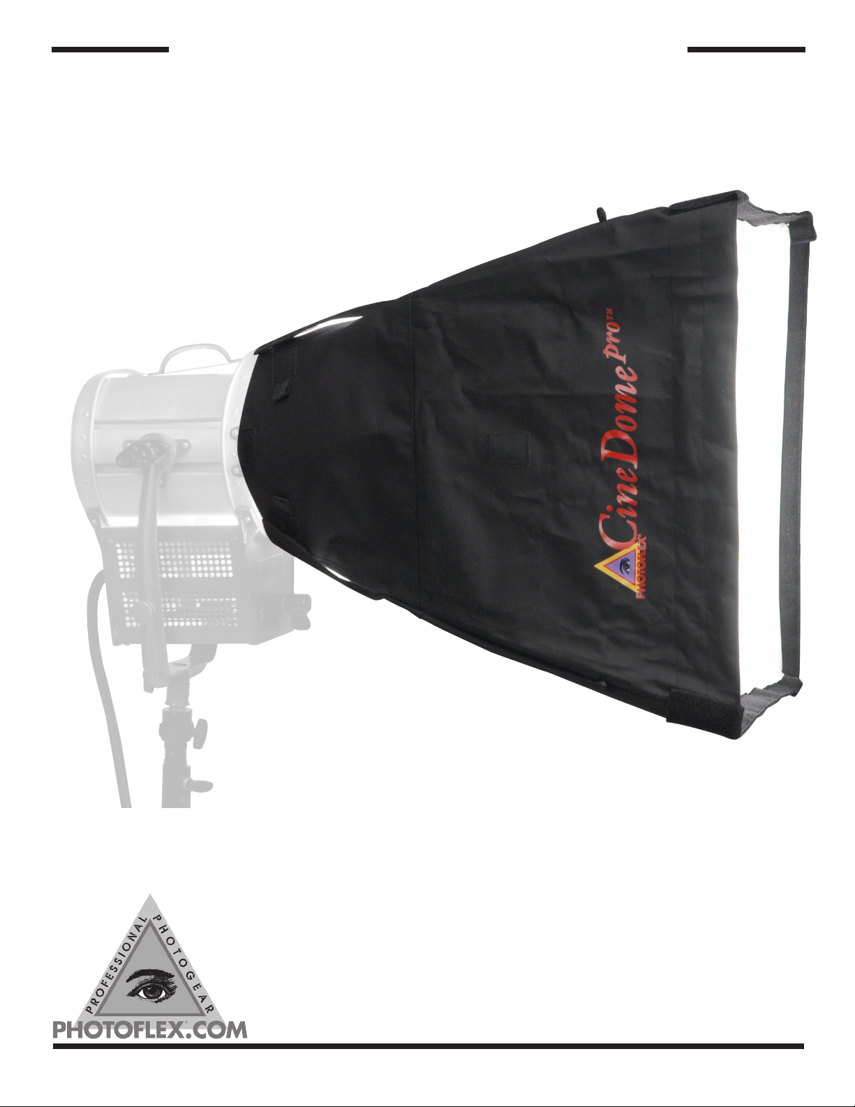
Photoflex CineDome
FV-CD1S, FV-CD2M, FV-CD3L
Customer Support (800)-486-2674
email [email protected]
Corporate Office (831) 786-1370 • FAX (831) 786-1371
97 Hangar Way, Watsonville, CA 95076
REV A 04/2009
Page 2
FV-CD1S, FV-CD2M, FV-CD3L
Steps in assembly
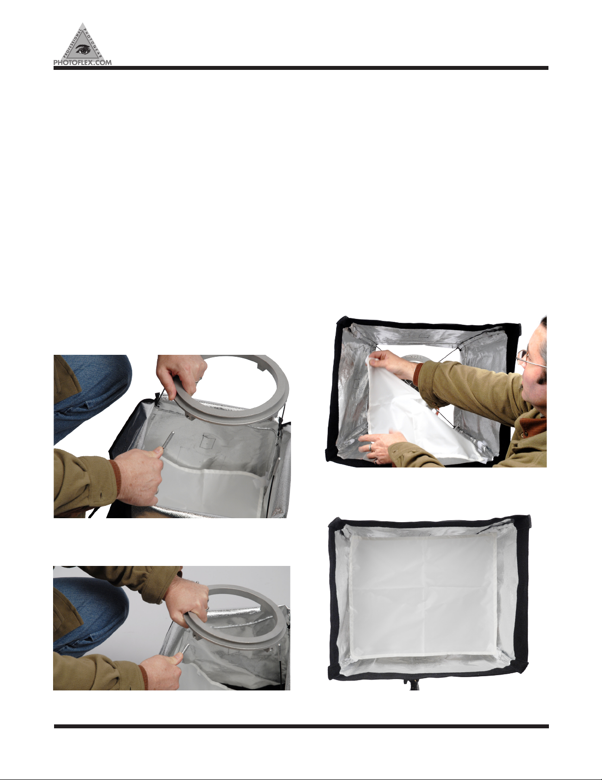
1. Inserting rods into connector
2. Installing inner baffle
3. Installing face diffuser
Parts List
CineDome soft box
Video connector to fit your specific light - (Sold sepa-
rately) Go to www.photoflex.com for a list of available
models
Four Steel rods
Inner baffle
Face diffuser
1. Inserting rods into the
connector
Place soft box face down on a flat, clean
surface. Insert the first rod into any receptacle on the con-
nector (Fig 1)
Insert the third rod through fourth rods following the order
in the same fashion as rods 1 and 2 above; inserting a rod
then inserting the one diagonal to it.
With all four rods positioned in the connector make sure
that all rod tips are securely seated into the connector’s
receiver holes by pushing down firmly on the connector to
ensure.
It is also a good idea to go around the front of the assembles dome and check each rod to be sure that the ends are
extended to the end of each sleeve.
The initial construction of the soft box is complete.
2. Installing Inner Baffle
The inner baffle has Velcro® tabs at each corner. These
tabs connect to the Velcro loops on each inner seam of
theCineDome.
Connect each corner of the inner baffle to each Velcro loop
inside the CineDome. (Fig 3)
Figure 1.
Insert the second rod into the hole diagonally opposite the
first hole. (Fig 2)
Figure 2.
2
Figure 3.
The baffle is installed. (Fig 4)
Figure 4
photoexlightingschool.com
Page 3
FV-CD1S, FV-CD2M, FV-CD3L
3. Installing The Face
Diffuser
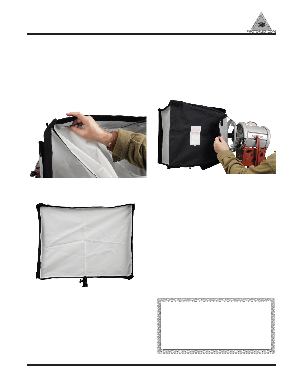
The face diffuser is rimmed with Velcro material that attaches to its counterpart that lines the front of the CineDome.
Find a corner of the diffuser and line up with the a corner
of the CineDome front. Starting at one corner, press the
face diffuser in place. Work your way around the rim of the
softbox until the diffuser is in place. (Fig 5)
Figure 5.
Your soft box is now fully constructed (Fig 6)
Safety Precautions:
1. This product is designed for use with hot light fixtures
but is not recommended for use with fixtures exceeding
2000 watts
2. Do not leave unattended when using with any constant
light fixture when lights are on as a hazardous situation
may be created.
3. Open Rear flaps as needed for ventilation (Fig 7)
Figure 7.
Figure 6.
Note: In most cases, the soft box connector is designed to
connect with your light head in the same manner as your
light head’s accessories such as “barn doors”. If using a
strobe light, make sure your Connector is the correct one
designed to fit your particular light.
PHOTOFLEX WARRANTY
• Warranties only cover manufacturer’s defects and
workmanship
• We reserve the right to inspect all merchandise returned
(end users and dealers) for warranty fulfillment.
• All returns must be accompanied by a receipt showing date
of purchase; waiver of this requirement will be at Photoflex’s
discretion.
• Freight must be paid both ways by the customer or dealer.
• Warranties are valid only from date of Original Purchase.
For warranty registration and information, please visit www.photoflex.com
3
 Loading...