

Page 1
General note
Please follow below instructions step by step. For more
detailed information or troubleshooting, please refer to the
User Manual (see CD-ROM). We recommend you to read
the User Manual to fully understand the system. Latest
versions of all documents can be downloaded on
www.phonomation.com.
INSTALLATION IN 8 STEPS
1. Check of contents
Please unpack carefully and check all items:
1
phonomator
®
1 mains cable
8 cable glands
1 documentation CD
1 quick installation guide
1 list of factory setting
1 drill template
4 screws and wall plugs
2. Mounting
Define the mounting position of the
phonomator® on
a planar wall.
Use a mobile phone to make sure that mobile phone
operation is possible in the chosen location.
A 230 VAC electric outlet must be within suitable distance
to plug in the provided power cable. Do not plug in the
plug yet!
Use the drill template when fixing your
phonomator
®
with the 4 provided wall plugs and screws.
3. Connect cables
Knock out 4 cable entries (see picture 2):
● The 2
nd
on the right for mains power.
● The 3
rd
on the right for motor cable.
● The 2
nd
on the left for lower photocell.
● The 3
rd
on the left for safety edge (with pre-limit
switch)
Mount 4 (or as much as you need for your application) of
the cable glands provided (see picture 2).
Connect cables (see picture 3 und 4).
CAUTION!
Electrical installation must only be
carried out by a qualified electrician!
picture 2 : Mounting position of cable glands
picture 4 : Connection of a lower
photocell and a safety edge with prelimit switch
Connecting the power input of the
photocell to terminal 3 (+12V) and 4
(SWGND= switched ground) allows
for selftesting of the photocell each
time the door will start to close.
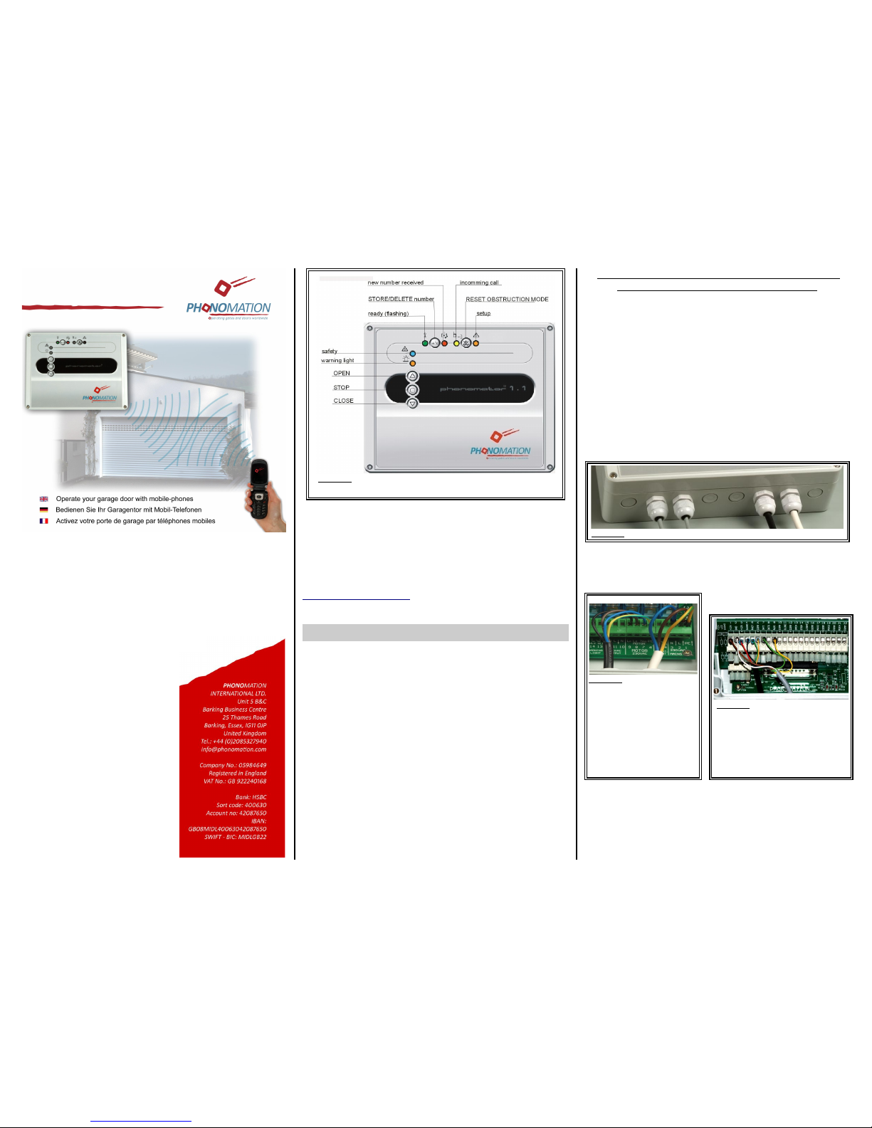
picture 1 : Main function of operating elements
Note: Colour of LED can only be seen when activated.
phonomator
®
This quick guide contains
important information Please
make sure to pass on this
document to the end-user
after installation.
QUICK INSTALLATION GUIDE
picture 3 : 230VAC connections
MAINS
Terminal 1: PE prot. earth
Terminal 2: L 230V phase
Terminal 3: N 230V neutral
MOTOR
Terminal 6: PE prot. earth
Terminal 7: NMOneutral
Terminal 8: LOphase/↑
Terminal 9: LCphase/↓
Version 3.1
Page 2
4. SIM-card preparation
For phone operation the
phonomator
®
needs a
SIM-card. Prior to use this card must be setup in a mobile
phone. If you are not familiar with mobile phones please
read your mobile phone manual or ask someone else to
do the following SIM-card setting:
1. PIN-code request must be deselected - or if this is
not possible - it must be set to „0000“ (4 x zero).
2. Any call forwarding must be deselected.
Power the mobile phone ON/OFF to check the correct
setting of the SIM-Card as follows:
1. Your mobile phone will not ask for the PIN or it will
accept „0000“ (4 x zero) as PIN.
2. Call the mobile phone from another phone.
Do not pick up or reject the call. Make sure that
your call will not be forwarded (e.g. to a mail box).
You might hear „the person you called is not
available ....“) or a similar information.
The SIM card is now ready to be installed in the
phonomator® as shown below :
5. Initial operation
Replace cover. Plug in mains cable.
As soon as the green LED will start flashing (after
about 30 sec.) your garage door will be connected to the
mobile phone network.
Your
phonomator
®
is now ready to be adapted to
your door.
6. Set max. running time of motor
1. Press push button for at least 10 seconds.
After releasing the button LED and LED
must be flashing alternately.
2. Adjust the limit switches of your door according to
the manufacturers' instructions.
(With push button and you can move the
door to any position.)
3. Press button to close the door completely.
4. Check the right setting of the limit switch for this
position of the door.
5. Press button to open the door completely.
6. Check the right setting of the limit switch for this
position of the door.
7. Push button briefly (do not keep pressed!).
LED and will stop flashing and the maximum running time will be stored.
8. Check if door can be properly operated by button
+ + .
Call your
phonomator
®
and listen to the number of
ringing tones you will hear:
If your call will be rejected after a short time (2 to 3 ringing
tones), the door will start to open. After a longer time (5 to
6 ringing tones), the door will start to close. Without being
in sight of your door you will thus know whether your door
will open or close.(Patent pending)
7. Check safety devices
While the door is closing check if moving direction will reverse when activating the photocell or the safety edge.
8. Authorise numbers
After initial set-up anyone who will know the phone number of the
phonomator
®
will be able to operate it.
To authorise your phone number just:
1. call the
phonomator
®
- red LED will light up.
2. Push button briefly (do not keep pressed!). Red
LED will switch off and green LED will jitter.
Only your phone number will now be authorised.
Other users (phone numbers) can be added accordingly.
By pressing push button for more than 3 seconds all
numbers will be deleted.
Up to 100 phone numbers can also be authorised and/or
deleted via SMS (text message) – see USER MANUAL.
Appendix: Terminal connection diagrams
(Numbering and notation as printed on PCB)
High voltage side
The closing contacts for the waring-light as well as for the
courtesy light are potential free (no power connected).
picture 5:
use your
fingertip to
open SIM
holder:
slide down –
lift up tray
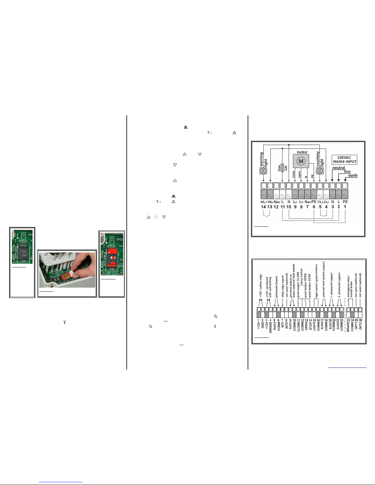
picture 8: Above terminals: connections for mains power and motor as
well as 230V circuit for warning light and courtesy light with external fuse.
Below terminals: Internal wiring.
______________________________________________
© Phonomation International Limited www.phonomation.com
picture 9: Connection of 12V safety devices and external operational
controls.
picture 7:
close SIM
holder and
slide tray up to
close
picture 6: insert SIM-card as shown
and drop holder
 Loading...