


direct digital synthesis FM
user guide
PE 560T transmitter
PE 500R receiver
PE 506R receiver
specs available on-line at www.phonicear.com

table of contents
Transmitter: PE 560T . . . . . . . . . . . . . . . . . . . . . . . . . . . . . . . . . . 1-2
Wide-band Receiver: PE 500R. . . . . . . . . . . . . . . . . . . . . . . . . . . . . . 3
Narrow-band Receiver: PE 506R . . . . . . . . . . . . . . . . . . . . . . . . . . . . 4
Ground Plane. . . . . . . . . . . . . . . . . . . . . . . . . . . . . . . . . . . . . . . . . . 5
Large Area Antenna . . . . . . . . . . . . . . . . . . . . . . . . . . . . . . . . . . . . . . 6
OnWave System Setup and Operation
Understanding hearing assistance . . . . . . . . . . . . . . . . . . . . . . . . . 7
Direct-mount a standard antenna. . . . . . . . . . . . . . . . . . . . . . . . . 7
Remote-mount a standard antenna. . . . . . . . . . . . . . . . . . . . . . . . . . . 8
Remote-mount a large-area antenna . . . . . . . . . . . . . . . . . . . . . . . 8
Mount the transmitter in rack or place on top of rack. . . . . . . . . . 9
Connect line input . . . . . . . . . . . . . . . . . . . . . . . . . . . . . . . . . . . 9
Connect microphone input . . . . . . . . . . . . . . . . . . . . . . . . . . . . 10
Activate phantom power . . . . . . . . . . . . . . . . . . . . . . . . . . . . . . 10
Adjust output levels (with adjustable volume). . . . . . . . . . . . . . . 11
Adjust output levels (without adjustable volume) . . . . . . . . . . . . 11
Music or speech? . . . . . . . . . . . . . . . . . . . . . . . . . . . . . . . . . . . . 12
Set bass cut . . . . . . . . . . . . . . . . . . . . . . . . . . . . . . . . . . . . . . . . 12
Set transmitter band & channel . . . . . . . . . . . . . . . . . . . . . . . . . 13
Tune PE 500R receiver . . . . . . . . . . . . . . . . . . . . . . . . . . . . . . . 13
Set PE 506R channel. . . . . . . . . . . . . . . . . . . . . . . . . . . . . . . . . 14
Walk and listen to confirm quality . . . . . . . . . . . . . . . . . . . . . . . 14
Lock/unlock your settings . . . . . . . . . . . . . . . . . . . . . . . . . . . . . 15
Save settings . . . . . . . . . . . . . . . . . . . . . . . . . . . . . . . . . . . . . . . 15
Receiver batteries. . . . . . . . . . . . . . . . . . . . . . . . . . . . . . . . . . . . 16
How to use the body-worn receiver . . . . . . . . . . . . . . . . . . . . . . 17
Warranty. . . . . . . . . . . . . . . . . . . . . . . . . . . . . . . . . . . . . . . . . . . . . 18
Troubleshooting . . . . . . . . . . . . . . . . . . . . . . . . . . . . . . . . . . . . . . . 19

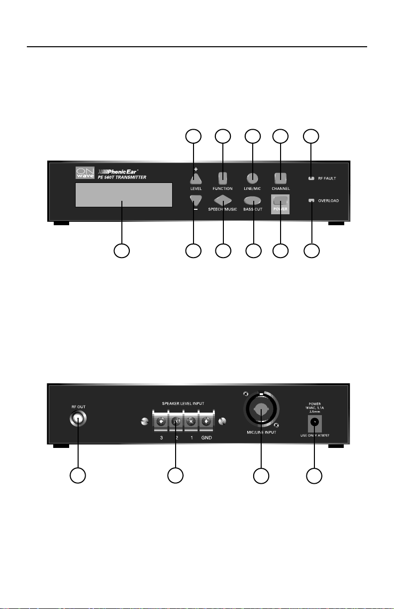
transmitter: PE 560T
1 digital display
2 level +
Increases output levels when the
volume of the sound source cannot
be adequately adjusted
3 level -
Reduces output levels when the
volume of the sound source cannot
be adequately adjusted.
4 function
Modifies the operation of other keys
(see step-by-step instructions on the
other side)
5 speech/music
The speech setting amplifies frequencies
in the 160Hz to 6kHz speech bandwidth, and can be further customized
using the bass cut options. The bandwidth for the music mode is expanded
to10kHz for a wider frequency response
and fuller sound.
6 line/mic
Press to select line or mic input (see 4b
on page 10).
7 bass cut
Listeners with high-frequency hearing
loss need high frequency emphasis and
low frequency de-emphasis. Press this
key to select 80Hz, 160Hz, or 320Hz
output levels for these individuals. Also
helps eliminate low frequency noise and
60 cycle electrical hum.
8 channel
Press the Channel key to select from 10
wide-band channels or 40 narrow-band
channels. (Press the Function key follo w ed
by the Channel key to switch between wide
1
and narrow-band transmission.Wide-band
channels are indicated by letters, narrowband channels are listed numerically.)
Check the front panel display to view the
channel being selected.
9 power
10 rf fault indicator
Lights if antenna is connected incorrectly
or if antenna is being detuned by other
electrical equipment
11 overload indicator
Lights if input exceeds maximum level for
transmitter. If this lights, reduce input
level to transmitter. (See 5a / 5b on
page 11 )
12 rf out
Screw in an AT0777 antenna or antenna
cable here (note that connector has lefthanded thread). US models are required
by the FCC to feature connectors unique
to Phonic Ear to prevent the use of nonregulation antennas. Contact your
Phonic Ear dealer.
13 speaker level input
To connect to levels of 2V, 10V or
70V
use the terminal block input
RMS
(sums inputs) and select the line level
setting on the front panel 6 .
14 universal line/mic input
Connect to sound system mixer via an
XLR or 1/4in cable. For connection to a
stand-alone mic use an XLR cable (see
page 11). Activate phantom power for
use with condenser mics.
15 power input
transmitter: PE 560T (cont’d)
front
2 4 6 8 10
3 5 7 9 111
12 13
back
14 15
2

wide-band receiver: PE 500R
Phonic Ear PE 500R
Wide Band Receiver
99 014737
22 volume/power
23 charge socket
1.3mm power jack. Connects to
PE 500C and AT0749 charger to
recharge NiCad batteries (Never
recharge Alkaline batteries!)
24 accessory socket
Connect listening accessories such
as teleloops, earbuds, and headsets.
3.5mm; stereo headset compatible.
25 indicator light
Lights when unit is on; flashes
when batteries are low (2 hours
remaining battery life); lights brighter
when charging
26 tuning screw
Multi-turn screw for setting the
receiver frequency.
Pre-tuned to 72.9 MHz
(channel E). (see 8b on page 13 )
22
front
23 24
25
back
27 battery door
Use 950mA/Hr rechargeable NiCad
or disposable alkaline batteries (never
recharge alkaline batteries!)
channel frequency channel frequency channel frequency
A 72.1 E 72.9 H 75.9
B 72.3 F 75.5 I 74.7
C 72.5 G 75.7 J 75.3
D72.7
26
3
27

narrow-band receiver: PE 506R
Phonic Ear PE 506R
99 014737
Narrow-Band Receiver
C
H
A
N
N
E
L
N
O
F
R
E
Q
C
O
D
E
7
8
9
10
11
12
33
34
35
36
37
38
+
—
— 72 MHz +
28 accessory/charge socket
3.5mm jack. Connect listening
accessories such as teleloops, earbuds, and headsets. Also connects to
PE 300C and AT0534 charger to
recharge NiCad batteries (Never
recharge Alkaline batteries!)
29 charge light
30 channel selector
Choose one of six different channels.
The frequency of each channel
is identified inside the battery
compartment (see 8C )
31 frequency code
label (inside)
Identifies the frequency code for
each of the six available channels
front
28
29
22
back
low band
frequency
channel code frequency
1 1 72.025
2572.225
31172.525
41472.675
5 17 72.825
6 19 72.925
27
mid band high band
channel code frequency
frequency
7 33 74.625
83474.675
93574.725
10 36 74.775
11 37 75.225
12 38 75.275
channel code frequency
13 22 75.475
14 24 75.575
15 26 75.675
16 28 75.775
17 30 75.875
18 32 75.975
30
31
frequency
4

ground plane (note that connectors have left-handed thread)
16 antenna jack
Attach antenna here
17 cable jack
Attach cable here
16
18 mounting holes
Use screws to mount on
a wall or, preferably, a
ceiling; may also be
placed on a tabletop
18
17
18
5

large area antenna
19 tuning ring
Do not deform or move
this ring, or you may
affect the antenna's
tuning and efficiency
20 worm clamps
Loosen both clamps; extend
the large center section to the
black ring; tighten lower
clamp; extend the smaller
element to the black ring;
tighten the top clamp
21 mounting hole/set screw
Use to mount on a tripod with
a mast. Ground your mounting
pole, tripod, or other holder to
a metal surface. You may also
hang the antenna from a railing
or metal superstructure (such as
in a stadium).
! warning
The antenna is an electrical
conductor. Contact with
power lines can result in
death or serious injury. Do
not install the antenna, supporting mast, or tower where
there is any possibility of contact with a high-voltage arc
from power cables or service
drops. Outdoor antennas
should be grounded against
lightning strikes. Consult the
National Electrical Code for
further details.
20
20
19
21
6

OnWave system setup and operation
understanding hearing
1
assistance
without the OnWave system
• distance
?
cough!
• noise
• echo
2a
but
direct-mount a
standard antenna
AT0777
PE 560T
1
then
2
cough!
100m
with the OnWave system
• distance
• noise
• echo
300ft
Attach antenna to back
1
of transmitter
Check RF Fault indicator.
2
If lit, adjust antenna
connection or remote
mount antenna.
or
continue to 2b
7

OnWave system setup and operation (cont’d)
2b
2c
remote-mount a
standard antenna
optimizes transmitter/antenna position
PE 560T
AT0775
AT0776
then
or
remote-mount a
large-area antenna
optimizes transmitter/antenna position
ground plane with
cable (AT0776)
or
ground plane with
connector kit
(AT0775)
PE 560T
100m
300m
300ft
1000ft
PE 560T
then
>2m/6ft
AT0773 Channels
A– E, 1–20
or
AT0774 Channels
F–J, 21– 40
PE 560T
NOTE:
! Ground mounting pole or
holder.
! Ground antenna if outdoors.
! Do not install near power
cables or service drops.
! Do not install parallel to metal
structure within 2m/6ft
(perpendicular to metal ok)
8

OnWave system setup and operation (cont’d)
mount the transmitter in rack
3
(requires remote mounting antenna)
or place on top of rack
AT0780/
AT0757
AT0781
2
Plug transformer into
1
OnWave power input
Plug transformer into
2
wall socket
1
or
4a
speaker terminal
9
connect line input
70V
block
10V
rms
rms2Vrms
or
or
then
GND
1
.25” pre-amp
100mV
rms
house system
2
Select Line-in
1
If overload indicator
2
lights when connecting
the sound system, use
XLR 250 mV
or
continue to 4b
rms
input

OnWave system setup and operation (cont’d)
4b
4c
connect microphone input
PE 560T
XLR input
2mV
1
then
rms
2
activate phantom power
(for electret condenser mics only†)
Plug in microphone
1
Select Mic-in
2
Press function
1
2
1
Press line/mic
2
Repeat steps to deactivate
phantom power
†Use phantom power only
with condenser microphones.
Plugging dynamic mic in
while phantom power is
activated may damage
the microphone
10

OnWave system setup and operation (cont’d)
adjust output levels
5a
(if your house system has adjustable volume)
5b
house system
1
2
4
6
or
3
adjust output levels
(if your house system has no adjustable volume
or if further adjustment is required)
house system
1
5
Turn on and play
1
test signal
Increase sound system
2
volume until...
...overload indicator lights
3
Slowly decrease sound
4
system volume until...
...overload indicator
5
goes out
Confirm that meter peaks
6
with signal
Turn on and play
1
test signal
Increase transmitter level*
2
until...
11
3
2
2-3 indicator bars appear
*
4
3
and peak with signal
Confirm that overload
4
indicator is off
* When transmitter level is
increased, the auto line level
control is activated and signal
strength is automatically adjusted for maximum volume without distortion or clipping.
OnWave system setup and operation (cont’d)
20
10
0
-10
-20
-30
-40
-50
-60
10
1
10
4
10
2
10
3
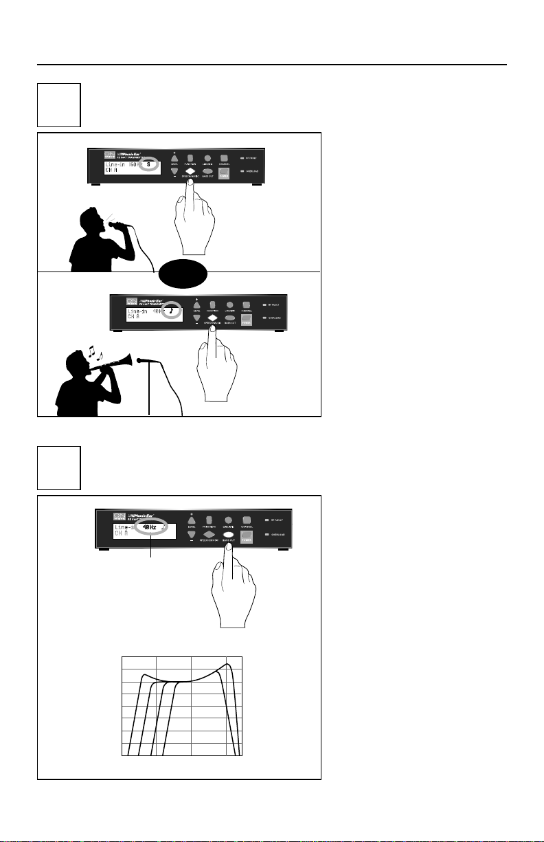
transmitted frequency response
4
0
H
z
speech
8
0
H
z
1
6
0
H
z
3
2
0
H
z
m
u
sic
music or speech?
6
(set for typical signal content)
or
set bass cut
7
(optimize for listeners or to reduce low-freq noise)
Recommended Standard Setting
Speech: 160Hz
Music: 40Hz
Recommended Noise Reduction Setting
(air conditioning, low frequency hum)
Speech: 160Hz
Music: 160Hz
12
OnWave system setup and operation (cont’d)
Phonic Ear PE 500R
Wide Band Receiver
99 014737
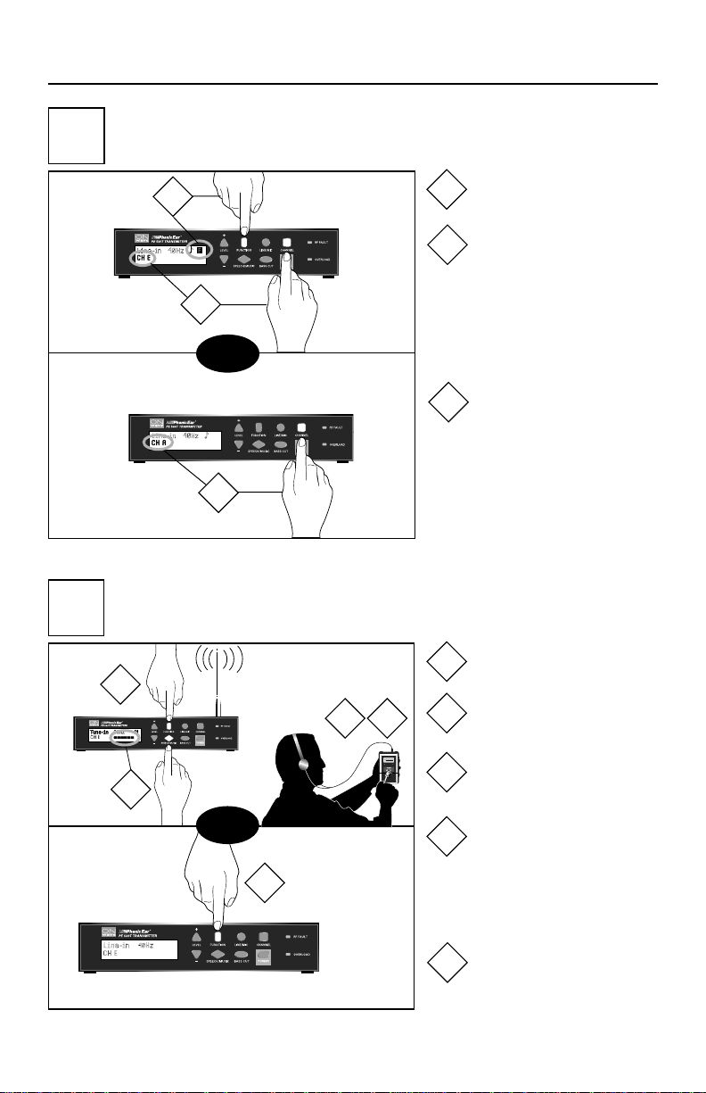
8a
8b
set transmitter band & channel
(optional; must tune your receiver to match!)
1
2
then
3
tune PE 500R receiver
(must match your transmitter!)
Press function
1
Press channel to select
2
wide-band for 500R
(channels indicated by
letters) or narrow-band
for 506R (channels
indicated by numbers)
Press channel to select
3
channel within your
chosen band
For narrow-band channel and
frequency information see 506R
receiver diagram on other side.
13
1
2
Press function
1
Press speech/music to
3 4
then
5
2
activate test tone
Set receiver at lowest
3
volume
Adjust screw until test
4
tone is audible
(Note: screw may require several turns to locate channel)
Press function to
5
deactivate test tone

OnWave system setup and operation (cont’d)
Phonic Ear PE 506R
99 014737
Narrow-Band Receiver
C
H
A
N
N
E
L
N
O
F
R
E
Q
C
O
D
E
7
8
9
10
11
12
1
5
11
14
17
19
+
–
– 72 MHz +
Phonic Ear PE 506R
Narrow-Band Receiver
99 014737
8c
9
set PE 506R channel
(must match your transmitter!)
1
1
then
2
2
walk and listen to confirm quality
(reposition antenna if necessary)
Find channel that
matches transmitter
frequency
Set channel
(Users can switch to
different channels if you
have set up multiple transmitters each with different
channel/program.)
14

OnWave system setup and operation (cont’d)
10
11
saves settings in temporary memory
lock/unlock your settings
save settings
or
2
4
1
3
1
Press function
1
Press level - to lock
2
Press function
3
Press level + to unlock
4
Press power to turn unit
1
off and save settings
saves settings permanently
if unplugging unit or power
outage occurs
15
or
2
1
Press function
1
Press power
2
OnWave system setup and operation (cont’d)
Phonic Ear PE 500R
Wide Band Receiver
99 014737
12
batteries are low
warning!
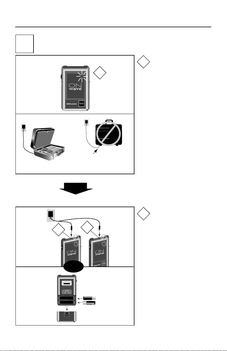
receiver batteries
Place charger case on its side when
connecting to charger cord.
1
Do not stand charger case on
bottom when charging. Damage
to charger may occur.
then
Light flashes when
1
2 hours of battery life
remain (4 hours with
alkaline battery)
charge
replace
AT0749
2
(PE 500R)
or
or AT0534
2
Push off
(PE 506R)
PE 500R or
PE 506R
Plug charger cord into
2
charger jack, not accessory jack
NOTE: Never recharge
Alkaline batteries
16

OnWave system setup and operation (cont’d)
how to use the body-worn
13
receiver
AT0489 wire clip
or
AT0737 pouch
or
AT0076
lavalier cord
17
1
then
then
2
On/Volume
1
(verify power light is on)
Switch to channel/
2
program (PE 506R only)

warranty
time period of warranty
This warranty will go into effect upon the date
of purchase and will stay in effect as long as
the instrument remains the property of the original owner. O
V
OCALIGHT
™
™
NWAVE
has a 3-year warranty;
has a 2 year warranty. All other
products have a 1 year warranty.
what is covered by this warranty
Any electronic component, which because of workmanship, manufacturing or design defects, fails to
function properly under normal use during the life of
this warranty will be replaced or repaired at no charge
for parts or labor, when returned to the factory
service center. Transportation in and out is paid by
the customer. If it is determined that repair is not
feasible, the entire unit may be replaced with an
equivalent unit upon mutual agreement of the
manufacturer and customer.
what is not covered by this warranty
This limited warranty does not apply to:
1. Malfunctions resulting from abuse, neglect
or accident
2.
I
nstruments connected, installed, used or adjusted
in any manner contrary to instructions provided
by the manufacturer
3. Consequential damages and damages resulting
from delay or loss of this instrument. The exclusive remedy under this warranty is strictly limited
to repair or replacement as herein provided
4. Products damaged in transit unless investigated
by the shipper and returned to the warrantor
with the investigation report
5. Peripheral accessories as itemized within the
product specification sheet as applicable, when
such items are returned within 90 days from
original purchase
6. Batteries if applicable
Phonic Ear Inc. reserves the right to make changes in
the design or construction of any of its instruments at
any time without incurring any obligation to make
any changes whatsoever on units previously purchased.
This warranty is in lieu of all other expressed warranties.
All expressed and implied warranties will terminate
upon the expiration of this written warranty . N o r epresentative or person is authorized to represent or assume
for us any liability in connection with the sale or use of
our products other than as set forth above.
what to do if you have questions
If you have any questions about service, call the service
department at
800.227.0735, then press 7.
what to do if you need service
If you require service under the warranty terms, obtain
a service order form either online at
com/support.asp
service department at
or through our U.S. customer
800.227.0735, then press 5
www.phonicear .
(or +1.707.769.1110 outside the U.S.). Fill the form
out completely remembering to include:
1. Description of the problem
2. Your billing address
3. Your shipping address (if different from
billing address)
4. Contact name and phone number
5. A P.O. number if the equipment is not under
a warranty or service contract
Then, carefully package the equipment in the
original shipping container
to prevent damage
and send it postpaid to the service center near you:
USA/International:
Phonic Ear Inc.
3880 Cypress Drive
Petaluma, CA 94954-7600
U.S.A.
In Canada:
Phonic Ear Ltd.
10-7475 Kimbel Street
Mississauga, Ontario
L5S 1E7 Canada
what to do if you have questions
If you have any questions about service, call the service
department at
about your batteries
800.227.0735, then press 7.
To ensure that your batteries are as fresh as possible
upon arrival, we have intentionally not installed
them in your equipment.
install your batteries in your equipment now,
then charge overnight before initial use
(see user guide for charging procedure).
avoid battery corrosion
To avoid battery corrosion and damage to your
equipment,
rechargeable alkaline batteries.
do not recharge disposable or
Before
charging any Phonic Ear equipment make sure
only NiCad or NiMH rechargeable batteries are
installed. As an added precaution, remove batteries
if the equipment will not be used for several weeks.
18

troubleshooting
no sound
• If using the 500R, verify the receiver is tuned correctly (see user instructions section 8b )
• If using the 506R, verify the channel selected on the receiver matches the channel selected on
the transmitter (see user instructions section 8c )
• If using 500R, check if the receiver power indicator light is on; if unlit, or flashing, replace or
recharge receiver batteries.
• Check if the transmitter is on (the front panel display window should be lighted).
• Verify the wall transformer is plugged into the transmitter and into a working wall outlet.
flashing light on receiver
• Replace or recharge batteries
sound too low/poor quality sound
• Check the transmitter line level indicators located in the display window. 2-3 bars should peak
with the audio signal. If no bars or only one bar appears, increase the volume on the sound
system and, if necessary, on the transmitter level control. Connect the sound system to the
1
/4in input on the transmitter for maximum output levels. Change to higher level output
connection on the sound system.
RF fault indicator is lighted
• Confirm that the antenna is connected properly to the transmitter. Relocate the antenna away from
any metal structures, power cords, or electronic equipment (see user instructions section 2b ).
intermittent audio
• Replace the receiver listening accessory.
• Check the RF fault indicator on the transmitter front panel and follow above instructions if lighted.
• The receiver may be out of range; for areas greater than 100m/300ft use a large area antenna.
overload indicator is lighted
• Confirm that the mic/line setting on the transmitter front panel is correct.
• Reduce the output level on the sound system.
• Connect the sound system to the XLR or speaker level inputs located on the back of the transmitter to reduce level.
• Change to lower output connection on the sound system.
low frequency hum
• Adjust the transmitter front panel bass cut settings to 160Hz or 320Hz
• Relocate the antenna away from electronic equipment, (see user instructions section 2b ).
batteries won’t recharge
• Verify that the wall transformer is plugged into the charger.
• Try different charge cords.
• Verify the receiver indicator light is brighter when the unit is plugged into charger.
• Check the receiver is turned off before charging.
• Check the receiver batteries are Nicad rechargeable.
19

us: 800.227.0735, then press 5 • canada: 800.263.8700
outside u.s./canada: Call your local Phonic Ear dealer • website: www.phonicear.com
© 2003 Phonic Ear Inc. Phonic Ear and the names of Phonic Ear products are trademarks or registered 821-7289-102/rev. E/3839 903
trademarks of Phonic Ear Inc. in the U.S. and other countries.
 Loading...