

Page 1
KT-8
User's Manual
Manual del Usuario
Page 2

KT-8
3-WAY LINE ARRAY SPEAKER
ALTAVOCES LINEARES ARRAY DE 3 VÍAS
ENGLISH .......................................I
ESPAÑOL ......................................II
APPENDIX ....................................III
V1.0 05/07/2015
KT-8
English Español
Page 3

3
KT-8
English
INTRODUCTION 1
FEATURES 1
ACCESSORIES 1
CONNECTORS 1
CONFIGURATION 1
WIRING 2
ASSEMBLY 2
SUGGESTED CONFIGURATION 3
SAFETY CONSIDERATIONS 4
APPENDIX
APPLICATIONS 1
DIMENSIONS 2
CONTENTS
USER'S MANUAL
Phonic preserves the right to improve or alter any information within this
document without prior notice
Page 4
4
KT-8
English
1. Read t hese instructions before operating t his
apparatus.
2. K eep these instructions for future reference.
3. H eed all warnings to ensure safe operation.
4. Follow all instructions provided in this document.
5. D o not use this apparatus near water o r in locations
where condensation may occ ur .
6. C lean only with d ry cloth. Do not use aerosol or liquid
cleaners. Unplug this apparatus before cleaning.
7. D o not block any of t he ventilation openings. Install
in accordance with the manufacturer
’
s instructions.
8. D o not install near any heat sources such a s radiators,
heat registers, stoves, or other apparatus (including
.
9. D o not defeat the safety purpose of t he polarized or
grounding-type plug. A polarized plug has two blades
with one wider than the other . A grounding type plug
has two blades and a third grounding p rong. The wide
blade or t he third prong is provided for your safety . If
the provided plug does not
into your outlet, consult
an electrician for replacement of the obsolete outlet.
10. Protect the power cord from being walked on o r
pinched particularly at plug, convenience receptacles,
and the point where they exit from the apparatus.
11 . Only use attachments/accessories
b y the
manufactur er .
12. Use only with a cart, s t and, t ripod, bracket, or
table
b y the manufacturer , or sold with
t he apparatus. When a c art is used, u se c autio n
when moving the cart/apparatus
combination to avoid injury from tip over .
13. Unplu g this apparatus during lighting
storms or w h en unused f or l on g
periods of time.
14. Refer all servicing to
service personnel.
Servicing is required when t he apparatus has been
damaged in any w ay , such as power-supply cord or
plug is damaged, liquid has been spilled or objects
have fallen into the apparatus, the apparatus has
been exposed to rain or m oisture, does not operate
normally , or has been dropped.
IMPORT ANT SAFETY INSTRUCTIONS
CAUTION: T O REDUCE THE RISK OF ELECTRIC SHOCK,
DO NOT REMOVE COVER (OR BACK)
NO USER SER VICEABLE P AR TS INSID E
REFER SER VICING T O QUALIFIED PERSONNEL
The lightning f lash with arrowhead symbol, w ithin an
equilateral triangle, is intended to alert the user to t he
presence of uninsulated
“
dangerous voltage ” within th e
product
’
magnitude to constitute a risk of electric shock to person s.
The exclamatio n point within an equilatera l triangle is i n-
tended to alert the user to the presence of important operat -
ing and maintenanc e (servicing ) instruction s in the literature
accompanying the applianc e.
W ARNING: To reduce the risk of or electric shock, do
not expose this apparatus to rain or moisture.
CAUTION: Use of controls o r adjustments o r performance
of procedures other than those
m ay result in
hazardous radiation exposure.
The apparatus shall not b e exposed t o dripping o r splashing and that n o objects
with liquids, such a s vases,
shall b e placed o n the apparatus. The MAINS plug i s used a s the disconnect device, the disconnect device shall
remain readily operable.
W arning : the user shall not place this apparatus i n the
area during the operation s o that the mains switch
can be easily accessible.
CAUTION
RISK OF ELECTRIC SHOC K
DO NOT OPEN
Installation should be performed by experienced, skilled
personnel only.
Inspection of hanging materials should be performed
before every use as to avoid accidents.
Ensure all locking devices are fitted correctly.
Ensure the capabilities of any lifting devices are greater
than the load being lifted.
Do not at any time use worn or defective materials.
Read this manual careful and retain for future reference.
Improper use of the array suspension system may result
in serious injury or critical damage to property.
Page 5
1
KT-8
English
INTRODUCTION
Congratulations on your purchase of another great
Phonic product. The KT-8 line array speakers were
carefully designed so as to provide phenomenal
performance in a low-weight, easily-manageable
constructions. Combined with your 2-way crossover
and power ampliers, the KT-8 passive line array
speakers can create phenomenal sound pressure
levels and extended coverage for all manner of largescale installations.
We know how eager you are to get started – getting
the speaker out and hooking up all your gear is probably your number one priority right now – but before
you do, be sure to carefully read through this manual.
Inside, you will nd important facts and gures on the
set up, use and applications of your brand new KT-
8. Remember that safe operation of a speaker is of
the utmost importance, so we strongly recommend
that users heed all warnings and instructions listed
in this manual.
FEATURES
48” bass-loaded woofer, 6.5” mid-range woofer with
2” voice-coils
4 Two 1.4” titanium diaphragm tweeters matched
with neodymium magnets
4Rated power (RMS): 150 Watts (LF), 110 Watts
(MF/HF)
4 Nominal Impedance: 16Ω (LF), 8Ω (MF/HF)
4Maximum sound pressure level: 128 dB (Peak)
4120° horizontal, 10° vertical dispersion pattern
4Straightforward rigging system allows splay
angles from 0° to 10°
4Exceptionally wide frequency response: 70Hz to
19KHz (-3dB)
4Bass-reex conguration for extended low-end
response
4Made of sturdy, multi-layer birch plywood with
tough black coating
4Two water and dust resistant Neutrik NL4 con-
nectors
ACCESSORIES
Included
U-Clip / Shackle
Flight Pins
Optional
Mounting Frame Model Number FF640 (640mm)
CONFIGURATION
The bi-amp system requires two amplier channels
to operate. Using a single cable, it is possible to connect the tweeter/mid-range and the woofer to their
own respective amplier channels. This conguration
guarantees greater sound delity, higher dynamism
and a signicant increase in sound pressure.
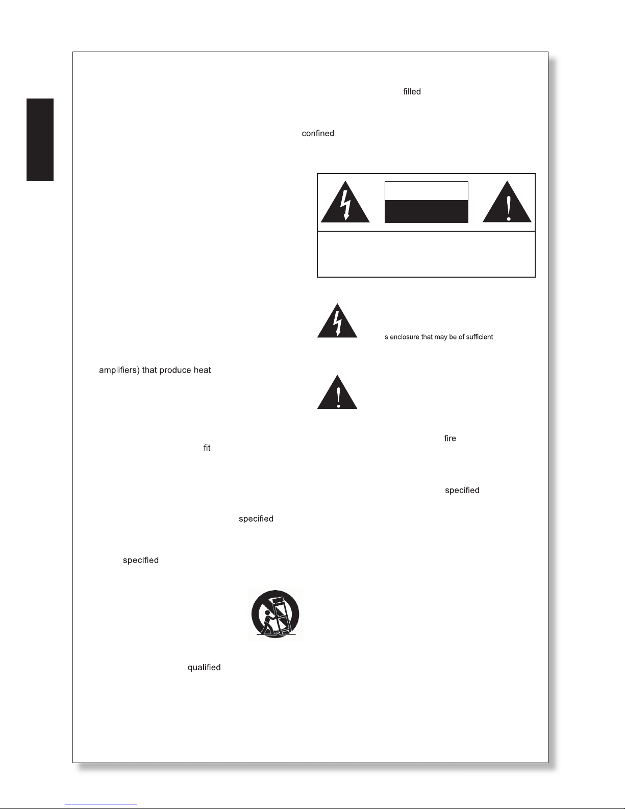
CONNECTORS
The KT-8 features a 4-pin NL4 speaker connection.
This provides positive and negative connectors for
the low frequency woofer as well as the mid-range
and tweeter.
The KT-8 line-array speaker has both an “IN” and a
“THRU” connector on the rear panel. The connector
labelled “IN” is for connecting your amplier to the
speaker, while the “THRU” connector is for chaining
additional speakers to share the amplier’s power.
1+
+
-
LF
HF
MF
2+
2-
1-
X-OVER
Page 6
2
KT-8
English
WIRING
Cables used to wire the KT-8 speakers should have
an appropriate diameter, as determined by the length
of the cables used. The resistance introduced by the
cable will reduce power output when run over long
distances. This being the case, a lower gauge cable
should be used when running over longer distances.
To avoid wasting amplier power we recommend use
of heavy-duty speaker cable (minimum 12 gauge).
Phonic suggests 10 gauge cable for longer distances.
Please note that extremely long distances may result
in resistive loss.
The image above indicates the polarity for each conductor found on the NL4 connector. Please ensure
this wiring is followed as to ensure correct operation
of the speaker.
Low
(-)
Low
(+)
High/
Low
(+)
High/
Low
(-)
1- 1+
2-2+
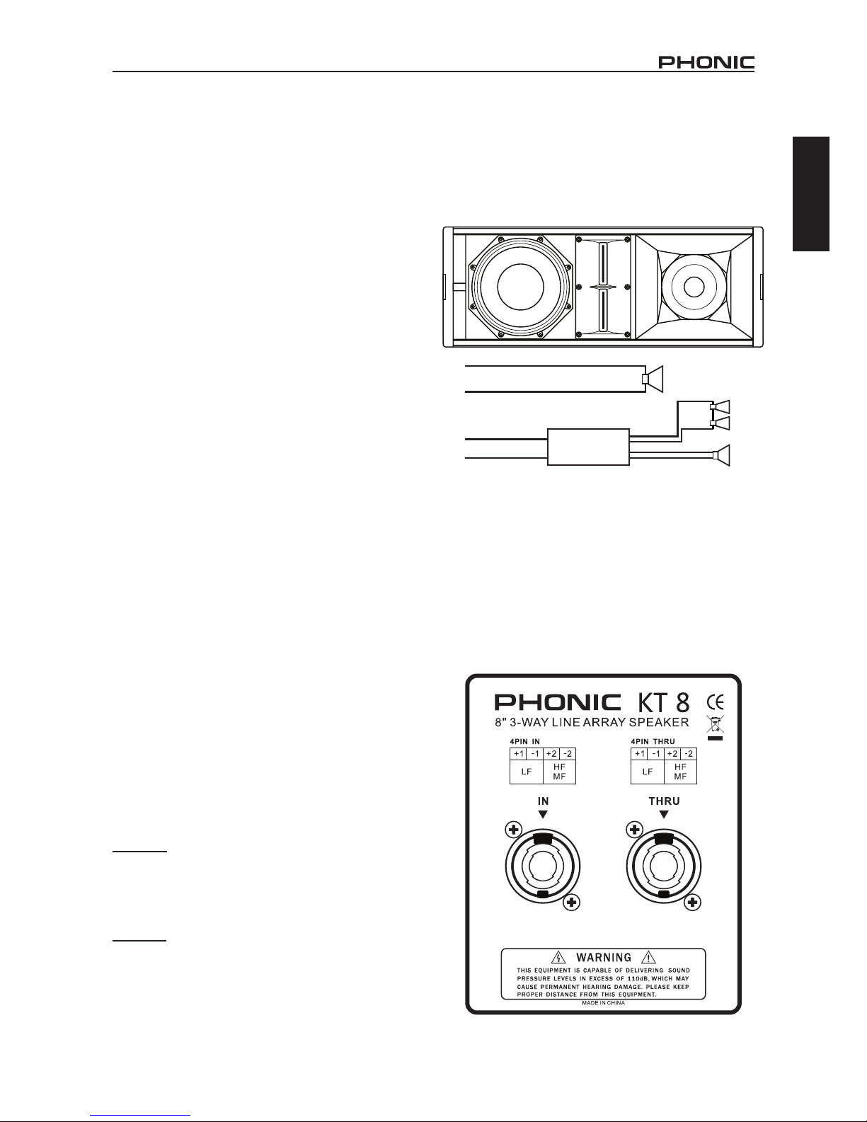
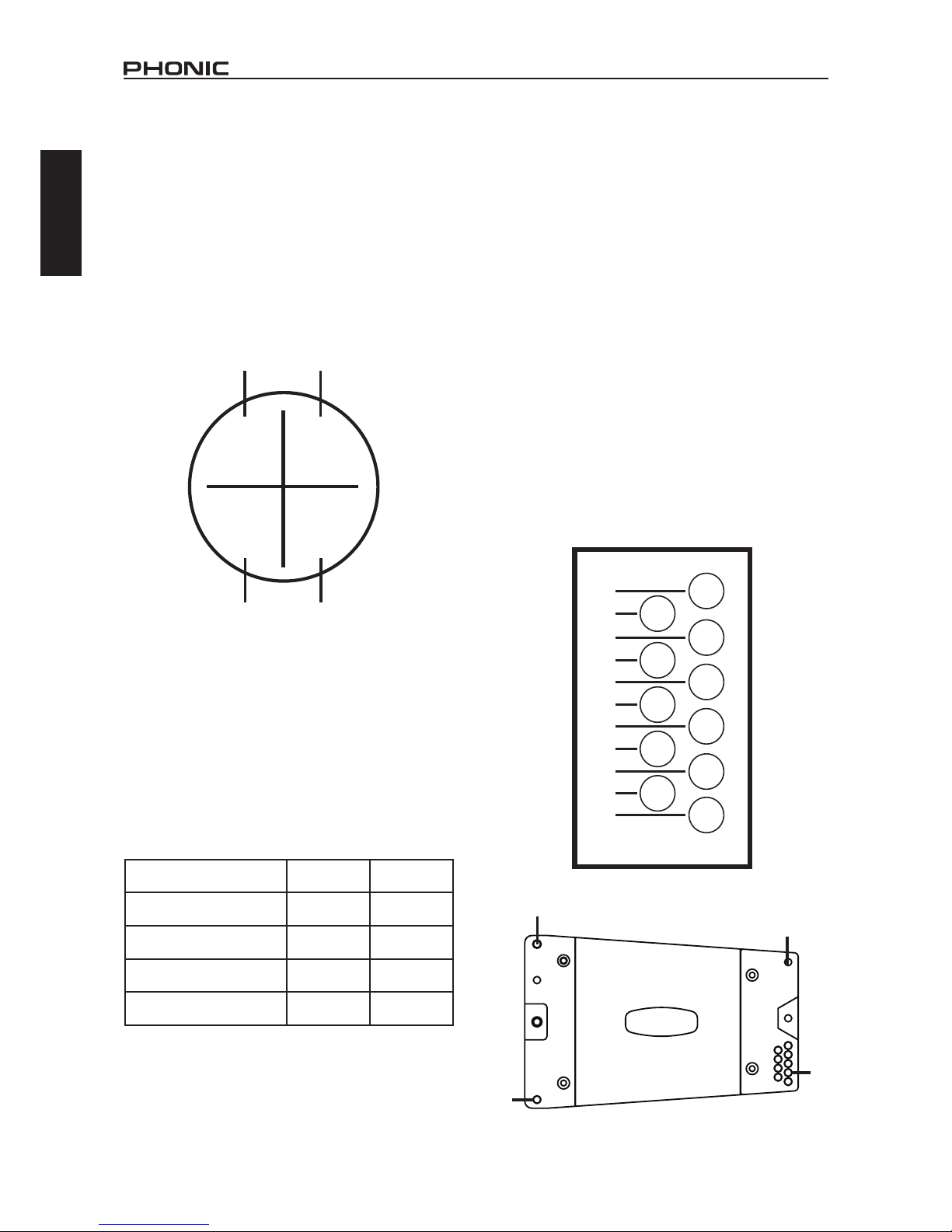
ASSEMBLY
The array conguration is accomplished through a
simple ‘pin-in-hole’ method of connection. The top
corners of the KT-8 each features a retractable joint
bar. These extend to be inserted into each of the four
slots at the bottom of the next unit in the array. The
four ight pins chained to the unit can be inserted in
the appropriate holes to x the units together.
The ight pins have a button on the end that can
be pushed to release the pin’s latch. This should
be pushed when inserting the pin into the mounting
holes.
The pins should sit ush with the side of the unit and
be unable to wiggle within the frame. To accomplish
this, the pin must be inserted completely through the
mounting holes on both of the KT-8 units being joined
in the array; through the outer-hole on the lower-part
of one unit, through the second unit’s joint bar, and
again through the rst unit’s inner-hole.
The lower-front corner of each unit features a single
mounting hole, while the lower-rear corner offers 11
individual holes that will determine the angle between
the two units. Connecting two units at 0° will create
narrower, yet more focused, dispersion. At 10° the
array will create a much wider vertical dispersion.
10°
9°
8°
7°
6°
5°
4°
3°
2°
1°
0°
NL4 Pin 1 (+/-) 2 (+/-)
Frequencies Low Mid / High
Speaker
8” 6.5” / 1.4
RMS Power Handling
150W 110W
Nominal Impedance
16Ω 8Ω
PIN HOLE
JOINT BAR
PIN HOLES
JOINT BAR
Page 7

3
KT-8
English
FLIGHT PIN
FLIGHT FRAME
(MODEL # FF640)
FLIGHT PIN
FLIGHT PIN
FLIGHT PIN
FLIGHT PIN
FLIGHT PIN
FLIGHT PIN
FLIGHT PIN
FLIGHT PIN
JOINT BAR
JOINT
BAR
0°
10°
FLIGHT PIN
10°
FLIGHT PIN
10°
FLIGHT PIN
10°
SUGGESTED CONFIGURATION
Page 8

4
KT-8
English
SAFETY CONSIDERATIONS
Please read all safety instructions found opposite
page 1 of this section of the manual.
KT-8 line array speakers should only be installed
by experienced personnel with adequate knowledge. Phonic takes no responsibility for incorrectly
mounted, suspended, or wired speakers, nor are we
responsible for issues arising from equipment not
inspected prior to use.
When working with the KT-8 line array systems, the
total working load should not exceed the resistance
of each individual component. This includes ight
pins, joint bars, ight frames and speaker cabinets.
While the Phonic ight frame and KT-8 speakers
have a maximum capacity of 1000 kg, consideration
of other elements of the setup should be taken into
consideration. This may including hoisting ropes and
other suspension materials.
Phonic suggests a safety ratio of 5:1. With this in
mind, a total load of 200 kg should be the aim when
creating your line array using the KT-8 and Phonic
FF640 ight frame. As previously stated, however,
the total resistance of other components of the setup
should be taken into account.
DO NOT ATTEMPT TO CARRY A LINE-ARRAY.
Under no circumstances should you attempt to lift a
line array by yourself. Mechanical winches and other
hoisting devices are recommended.
The KT-8 is equipped with an internal passive crossover for mid/highs. There is no crossover present on
the woofer. Please note that incorrectly wired speakers may cause damage to the unit.
Phonic recommends taking the utmost of care
when wiring and/or connecting speakers. A 2-way
crossover with a crossover point at 500Hz is best to
separate low frequencies from the mid/highs. The
ideal frequency range for the KT-8’s 8” woofer is
60Hz to 500Hz, while the mid/high range works best
at 500Hz to 20 kHz.
Page 9

5
KT-8
English
KT-8
Woofers 8"
Mid-range 6.5"
Tweeter Two 1.4" titanium diaphragm compression drivers
Frequency Range (-3dB) 70Hz - 19KHz
Horizontal Coverage 120°
Vertical Coverage 10°
RMS Power Handling
LF: 150 Watts
MF/HF: 110 Watts
On-Axis Sensitivity 1W/1m
LF: 96 dB
MF: 102 dB
HF: 105 dB
Rated Maximum Peak SPL at 1m
LF: 126 dB
MF: 129 dB
HF: 129 dB
Nominal Impedance
LF: 16Ω
MF/HF: 8Ω
Recommended Amplier Power
LF: 300W
MF/HF: 220W
Enclosure Material
18mm multi-layer birch plywood, 8mm hexagonal
black steel mesh with special accoustical foam
Color Black
Rigging System Included (0° to 10°)
Connectors 2 x Neutrik NL4
Dimension (HxWxD) 640 x 380 x 240 mm (25.2" x 15" x 9.4")
Weight 26 Kg (57 lbs)
SPECIFICATIONS
Page 10

6
KT-8
English Español
CONTENIDO
Manual del Usuario
Phonic se reserva el derecho de mejorar o alterar cualquier información
provista dentro de este documento sin previo aviso.
INTRODUCCIÓN 1
CARACTERÍSTICAS 1
ACCESORIOS 1
CONFIGURACIÓN 1
CONECTORES 1
CABLEADO....................................................................................2
MONTAJE..........................................................................2
CONFIGURACIÓN SUGERIDA.............................................3
CONSIDERACIONES DE SEGURIDAD 4
ESPECIFICACIONES 5
APÉNDICE
APLICACIONES 1
DIMENSIONES 2
Page 11

7
KT-8
English Español
La instalación debe ser realizada por un personal
cualificado y experimentado.
Una Inspección de materiales colgantes debe ser
realizada antes de cada uso para evitar accidentes.
Asegurarse de que todos los dispositivos de bloqueo de
seguridad están instalados correctamente.
Asegúrese de que los dispositivos de suspensión no
sujetan una carga superior de lo previsto.
No usar materiales de suspensión viejos o defectuosos.
Lea este manual atentamente y guárdelo para futuras
consultas.
El uso inapropiado del sistema de suspensión puede provocar
lesiones graves o daño crítico a la propiedad.
Page 12

1
KT-8
English Español
INTRODUCCIÓN
Le damos la enhorabuena por comprar otro gran producto
de Phonic. Los altavoces line array KT-8 lineares fueron
cuidadosamente diseñados para proporcionar un rendimiento fenomenal. Su construcción le permite ser ligero
y fácilmente manejable. Combinado con un crossover de
2 vías y amplicadores de potencia, los altavoces pasivos
line Array KT-8 pueden crear niveles de presión sonora
fenomenal y cobertura extendida para todo tipo de instalaciones a gran escala.
Sabemos que está impaciente para empezar - conseguir
el altavoz y conectar todo su equipo es probablemente su
prioridad número uno ahora mismo - pero antes de hacerlo, asegúrese de leer cuidadosamente este manual. En
el interior, encontrará datos y cifras importantes sobre la
conguración, uso y aplicaciones de su nueva KT-8. Recuerde que utilizar el altavoz de forma segura es sumamente
importante, por lo que se recomienda que los usuarios
presten atención a todas las advertencias e instrucciones
que guran en este manual.
CARACTERÍSTICAS
4Woofer de 8”, Woofer de gama media de 6.5” con
bobinas de voz de 2”
4Tweeter de 1.4” con diafragma de titanio e imanes
de neodimio (Dos)
4Potencia nominal (RMS): 150 vatios (LF), 110
vatios (MF / HF)
4Impedancia nominal: 16Ω (LF), 8Ω (MF / HF)
4Nivel de presión acústica máxima: 128 dB (Pico)
4Dispersión horizontal 120°, vertical 10°
4Sistema de aparejo sencillo permite ángulos de
separación de 0° a 10°
4Respuesta de frecuencia excepcionalmente am-
plia: 70Hz a 19KHz (-3 dB)
4Conguración Bass-reex para una respuesta de
gama baja ampliada
4Hecho de múltiples capas de abedul contracha-
pado con revestimiento resistente negro
4Dos conectores Neutrik NL4 resistentes al agua
y al polvo
ACCESORIOS
Incluido
U-Clip / Grillete
Flight Pins/ Bola pasador
Opcional
Número de modelo del marco de montaje FF640
(640mm)
CONFIGURACIÓN
Para operar el sistema bi-amp requiere dos canales
de amplicación. Es posible conectar el Tweeter / de
gama media y el Woofer, a sus respectivos canales
de amplicación con un solo cable. Esta conguración garantiza una reproducción de sonido más el,
mayor dinamismo y un aumento signicativo en la
presión acústica.
CONECTORES
El KT-8 cuenta con un conector de altavoces de 4
pines NL4. Esto proporciona conectores positivos
y negativos para el Woofer de baja frecuencia, y el
Tweeter de gama media.
El altavoz line-array KT-8 posee ambos conectores
“IN” y “THRU” en el panel posterior. El conector mar-
cado “IN” conecta el amplicador al altavoz, mientras
que el conector “THRU” encadena altavoces adicio-
nales para compartir el poder del amplicador.
1+
+
-
LF
HF
MF
2+
2-
1-
X-OVER
Page 13

2
KT-8
English Español
CABLEADO
Los cables utilizados para conectar los altavoces
KT-8 deben tener un diámetro adecuado. Ese diámetro se determina según la longitud de los cables
utilizados. La resistencia presentada por el cable
reducirá la potencia de salida de la señal cuando esa
está transferida a través largas distancias. Siendo
este el caso, un cable de menor diámetro se debe
utilizar en distancias más largas.
Para evitar la pérdida de potencia del amplicador,
se recomienda el uso de un cable de altavoz extrafuerte (calibre 12 mínimo). Phonic sugiere un cable
de calibre 10 para distancias más largas. Tenga en
cuenta que muy largas distancias pueden resultar
en pérdida de resistencia.
La imagen de arriba indica la polaridad de cada
conductor que se encuentra en el conector NL4. Por
favor, asegúrese que este cableado es seguido para
garantizar el funcionamiento correcto del altavoz.
Baja
(-)
Baja
(+)
Medias/
Altas
(+)
Medias/
Altas
(-)
1- 1+
2-2+
MONTAJE
La conguración de la matriz se lleva a cabo a través
de un método sencillo de conexión con pines de
bola de pasador. Cada esquina superior de la KT-8
dispone de una articulación retractable. Estas se
extienden para ser insertadas en cada una de las
cuatro ranuras en la parte inferior de la siguiente
unidad. Los pines de bola de pasador encadenados
a la unidad pueden ser insertados en los oricios
adecuados para jar las unidades juntas.
Los pines de bola de pasador tienen un botón en el
extremo que se puede empujar para liberar el pestillo
de la clavija. Esto debe ser empujado al insertar la
clavija en los oricios de montaje.
Los pines de bola de pasador deben estar al ras de la
unidad, y esta debería ser incapaz de mover dentro
del marco de construcción. Para lograr esto, el pin
bola de pasador debe insertarse completamente a
través de los oricios de montaje en ambas unidades
KT-8; a través de los oricios de montaje situados
en la parte inferior de la unidad, a través de la barra
de articulación de la segunda unidad, y en el centro
de la primera unidad.
La esquina inferior, en la parte frontal de cada uni-
dad cuenta con un oricio de montaje. Mientras que
la esquina inferior en la parte trasera de la unidad
ofrece 11 oricios de montaje individuales que van
a determinar el ángulo de dispersión acústica entre
las dos unidades. Si conecta dos unidades a 0 °
creará una dispersión acústica más estrecha, pero
más centrada. A los 10° las unidades crearán una
dispersión vertical mucho más amplia.
10°
9°
8°
7°
6°
5°
4°
3°
2°
1°
0°
Machos/Pines de
enchufe NL4
1 (+/-) 2 (+/-)
Frecuencias Baja
Medias/
Altas
Altavoz
8” 6.5” / 1.4
Manejo de Potencia
RMS
150W 110W
Impedancia Nominal
16Ω 8Ω
BARRA DE ARTICULACIÓN
INSERTOS DE PINES
DE CONEXIÓN
INSERTOS DE PINES
DE CONEXIÓN
Page 14

3
KT-8
English Español
INSERTOS DE PINES DE CONEXIÓN
MARCO DE MONTAJE
(MODELO # FF640)
INSERTOS DE PINES
DE CONEXIÓN
INSERTOS DE PINES
DE CONEXIÓN
INSERTOS DE PINES DE CONEXIÓN
INSERTOS DE PINES DE CONEXIÓN
INSERTOS DE PINES DE CONEXIÓN
INSERTOS DE PINES DE CONEXIÓN
INSERTOS DE PINES DE CONEXIÓN
INSER
TOS DE PINES DE CONEXIÓN
BARRA DE ARTICULACIÓN
0°
10°
10°
INSERTOS DE PINES DE CONEXIÓN
INSERTOS DE PINES DE CONEXIÓN
INSERTOS DE PINES DE CONEXIÓN
INSERTOS DE PINES DE CONEXIÓN
10°
10°
CONFIGURACIÓN SUGERIDA
Page 15

4
KT-8
English Español
NO INTENTE LEVANTAR UN LINE-ARRAY/
CONJUNTO DE ALTAVOCES. Bajo ninguna
circunstancia se debe intentar levantar un A rray
por sí mismo. Se recomienda utilizar diversos
dispositivos mecánicos de elevación.
El KT-8 está equipado con un Crossover pasivo
interno para medias/altas. No hay Crossover
presente en el Woofer. Tenga en cuenta que los
altavoces incorrectamente cableados/montados
pueden causar daños a la unidad.
Phonic recomienda tomar el máximo cuidado al
realizar el cableado y / o la conexión de los altavoces.
Un Crossover de 2 vías con un punto de corte en
500Hz es mejor separar las frecuencias bajas de
las frecuencias medias/altas. El rango de frecuencia
ideal para el Woofer de 8” del KT-8 es de 60 Hz a
500 Hz, mientras que la gama media/alta funciona
mejor de 500 Hz a 20 kHz.
Le pedimos que lea todas las instrucciones de
seguridad, las cuales se encuentran junto la página
1 de esta sección del manual.
Los altavoces KT-8 sólo deben ser instalados por
un personal experimentado con el conocimiento
adecuado. Phonic no se responsabiliza de los
altavoces montados incorrectamente que esos sean,
suspendidos o cableados, ni somos responsables
de un equipo que no ha sido inspeccionado antes
de su uso.
Cuando se trabaja con los sistemas line Array KT-8,
la carga total nunca debería superar la capacidad
de resistencia de cada componente individual. Esto
incluye Los pines de bola de pasador, articulaciones
de barras, marco de construcción de suspensión y
de los altavoces.
Mientras que el marco de construcción de suspensión
de los altavoces KT-8 de Phonic tiene una capacidad
de resistencia máxima de 1.000 kg, el examen de
otros elementos de la instalación debe ser tomado
en consideración. Esto puede incluir cables y otros
materiales de suspensión.
Phonic sugiere una margen de seguridad basada
en 1/5 (un quinto) de la capacidad de resistencia
de peso en total. Con esto en la mente, el peso
máximo del conjunto de Altavoces KT-8 / (Array) no
debería alcanzar más de 200 kg utilizando el marco
de construcción de suspensión de Phonic FF640.
Como se indicó anteriormente, sin embargo, el peso
y la resistencia total de otros componentes de la
conguración deben ser tomados en cuenta.
CONSIDERACIONES DE SEGURIDAD
Page 16

5
KT-8
English Español
KT-8
Woofers 8"
Rango-Medio 6.5"
Tweeter Dos driver de compresión diafragma de titanio de 1.4"
Gama de Frecuencia (-3dB) 70Hz - 19KHz
Cobertura Horizontal 120°
Cobertura Vertical 10°
Manejo de Potencia RMS
LF: 150 Vatios
MF/HF: 110 Vatios
Sensibilidad On-Axis 1W / 1m
LF: 96 dB
MF: 102 dB
HF: 105 dB
Capacidad Maxima de Pico / Rated
Maximum Peak SPL at 1m
LF: 126 dB
MF: 129 dB
HF: 129 dB
Impedancia Nominal
LF: 16Ω
MF/HF: 8Ω
Amplicación de Potencia
Recomendada
LF: 300W
MF/HF: 220W
Material de la Caja
Multicapa de abedul contrachapado de 18mm,
malla de acero negra hexagonal de 8 mm
con espuma acústica especial
Color Negro
Sistema Aparejo Incluido (0° to 10°)
Conectores 2 x Neutrik NL4
Dimensiones (HxWxD) 640 x 380 x 240 mm (25.2" x 15" x 9.4")
Peso 26 Kg (57 lbs)
ESPECIFICACIONES
LINK/
ENLACE
LINK/ENLACE
LINK/
ENLACE
PHONIC i2600 SPEAKER
MANAGEMENT SYSTEM
SUGGESTED CROSSOVER
FREQUENCY: 500Hz (-24dB/Oct)
CROSSOVER de 500Hz (-24 dB/Oct)
iAMP3020
AMPLIFIERS /
AMPLIFICADORAS
MIXER/
MEZCLADORA
HIGH/
MID
LOW/
BAJAS
RL
LINK/
ENLACE
ALTAS/
MEDIAS
Page 17

1
KT-8
Appendix Apéndice
KT-8
APPLICATIONS APLICACIONES
KT-8
LINK/
ENLACE
LINK/ENLACE
LINK/
ENLACE
PHONIC i2600 SPEAKER
MANAGEMENT SYSTEM
SUGGESTED CROSSOVER
FREQUENCY: 500Hz (-24dB/Oct)
CROSSOVER de 500Hz (-24 dB/Oct)
iAMP3020
AMPLIFIERS /
AMPLIFICADORAS
MIXER/
MEZCLADORA
HIGH/
MID
LOW/
BAJAS
RL
LINK/
ENLACE
ALTAS/
MEDIAS
In the above conguration, the front of house mix is
sent to a 2-way crossover before being sent to power
ampliers. The KT-8 speakers are then powered by
at least two separate power ampliers. A crossover
point of 500 Hz is suggested. For information on wiring the NL4 connectors of the KT-8 please consult
page 2 of this manual.
The array conguration has each speaker at a 10
degree angle. This provides wider vertical coverage,
able to cover longer distances for larger audiences.
Congurations can vary. For more direct, robust
audio, for example, the top two or three speakers
can be mounted at a 0 degree angle, while the lower
speakers can sit at 8 or 10 degrees. See the “Sug-
gested Conguration” section for one such example.
En la conguración anterior, la mezcla frontal se
envía a un cruce/Crossover de 2 vías antes de
ser enviada a los amplicadores de potencia. Los
altavoces KT-8 son entonces alimentados por (al
menos) dos amplicadores de potencia separados.
Para obtener información sobre el cableado de los
conectores NL4 del KT-8 por favor consulte la página
2 de este manual.
Cada altavoz de la conguración Array está colocado en un ángulo de 10 grados. Esto proporciona
una cobertura vertical más amplia, capaz de cubrir
grandes distancias para grandes audiencias. Las
conguraciones pueden variar. Para un audio más
robusto y más directo, por ejemplo, los dos o tres
altavoces de la parte superior del Array se pueden
montar en un ángulo de 0 grados, mientras que los
altavoces inferiores pueden ajustar en 8 o 10 grados.
Vea la sección “Conguraciones sugeridas” para
observar este ejemplo.
Page 18

2
KT-8
Appendix Apéndice
Measurements are shown in mm/inches
DIMENSIONS DIMENSIONES
Todas las medidas están mostradas en mm/pulgadas
380 / 15
640 / 25.2
240 / 9.4
380 / 15
8°
640 / 25.2
240 / 9.4
Page 19

3
KT-8
Appendix Apéndice
NOTES
Page 20

 Loading...