

Page 1
KT-8A
KT-210A
User's Manual
Manual del Usuario
Page 2

KT-8A / KT-210A
3-WAY ACTIVE LINE ARRAY SPEAKER
ALTAVOCES LINEARES ARRAY DE 3 VÍAS
ENGLISH .......................................I
ESPAÑOL ......................................II
APPENDIX ....................................III
V1.0 06/30/2015
KT-8A
KT-210A
English Español
Page 3

3
KT-8A / KT-210A
English
INTRODUCTION 1
FEATURES 1
ACCESSORIES 1
CONNECTORS 1
CONFIGURATION 1
WIRING 2
ASSEMBLY 2
SUGGESTED CONFIGURATION 3
SAFETY CONSIDERATIONS 4
APPENDIX
APPLICATIONS 1
DIMENSIONS 2
CONTENTS
USER'S MANUAL
Phonic preserves the right to improve or alter any information within this
document without prior notice
Page 4
4
KT-8A / KT-210A
English
1. Read t hese instructions before operating t his
apparatus.
2. K eep these instructions for future reference.
3. H eed all warnings to ensure safe operation.
4. Follow all instructions provided in this document.
5. D o not use this apparatus near water o r in locations
where condensation may occ ur .
6. C lean only with d ry cloth. Do not use aerosol or liquid
cleaners. Unplug this apparatus before cleaning.
7. D o not block any of t he ventilation openings. Install
in accordance with the manufacturer
’
s instructions.
8. D o not install near any heat sources such a s radiators,
heat registers, stoves, or other apparatus (including
.
9. D o not defeat the safety purpose of t he polarized or
grounding-type plug. A polarized plug has two blades
with one wider than the other . A grounding type plug
has two blades and a third grounding p rong. The wide
blade or t he third prong is provided for your safety . If
the provided plug does not
into your outlet, consult
an electrician for replacement of the obsolete outlet.
10. Protect the power cord from being walked on o r
pinched particularly at plug, convenience receptacles,
and the point where they exit from the apparatus.
11 . Only use attachments/accessories
b y the
manufactur er .
12. Use only with a cart, s t and, t ripod, bracket, or
table
b y the manufacturer , or s old with
t he apparatus. When a c art is used, u se c autio n
when moving the cart/apparatus
combination to avoid injury from tip over .
13. Unplu g this apparatus during lighting
storms or w h en unused f or l on g
periods of time.
14. Refer all servicing to
service personnel.
Servicing is required when t he apparatus has been
damaged in any w ay , such as power-supply cord or
plug is damaged, liquid has been spilled or objects
have fallen into the apparatus, the apparatus has
been exposed to rain or m oisture, does not operate
normally , or has been dropped.
IMPORT ANT SAFETY INSTRUCTIONS
CAUTION: T O REDUCE THE RISK OF ELECTRIC SHOCK,
DO NOT REMOVE COVER (OR BACK)
NO USER SER VICEABLE P AR TS INSID E
REFER SER VICING T O QUALIFIED PERSONNEL
The lightning f lash with arrowhead s ymbol, w ithin an
equilateral triangle, is intended to alert the user to t he
presence of uninsulated
“
dangerous voltage ” within th e
product
’
magnitude to constitute a risk of electric shock to person s.
The exclamatio n point within an equilatera l triangle is i n-
tended to alert the user to the presence of important operat -
ing and maintenanc e (servicing ) instruction s in the literature
accompanying the applianc e.
W ARNING: To reduce the risk of or electric shock, do
not expose this apparatus to rain or moisture.
CAUTION: Use of controls o r adjustments o r performance
of procedures other than those
m ay result in
hazardous radiation exposure.
The apparatus shall not b e exposed t o dripping o r splashing and that n o objects
with liquids, such a s vases,
shall b e placed o n the apparatus. The MAINS plug i s used a s the disconnect device, the disconnect device shall
remain readily operable.
W arning : the user shall not place this apparatus i n the
area during the operation s o that the mains switch
can be easily accessible.
CAUTION
RISK OF ELECTRIC SHOC K
DO NOT OPEN
Installation should be performed by experienced, skilled
personnel only.
Inspection of hanging materials should be performed
before every use as to avoid accidents.
Ensure all locking devices are fitted correctly.
Ensure the capabilities of any lifting devices are greater
than the load being lifted.
Do not at any time use worn or defective materials.
Read this manual careful and retain for future reference.
Improper use of the array suspension system may result
in serious injury or critical damage to property.
Page 5
1
KT-8A / KT-210A
English
INTRODUCTION
Congratulations on your purchase of another great
Phonic product. The KT-8A and KT-210A line array
speakers were carefully designed so as to provide
phenomenal performance in a low-weight, easilymanageable constructions. These active line array
speakers provide extensive signal processing as
well as reliable and robust amplication to provide
phenomenal sound pressure levels in all manner of
large-scale installations.
We know how eager you are to get started – getting
the speaker out and hooking up all your gear is probably your number one priority right now – but before
you do, be sure to carefully read through this manual.
Inside, you will nd important facts and gures on the
set up, use and applications of your brand new KT8A or KT-210A. Remember that safe operation of a
speaker is of the utmost importance, so we strongly
recommend that users heed all warnings and instructions listed in this manual.
FEATURES
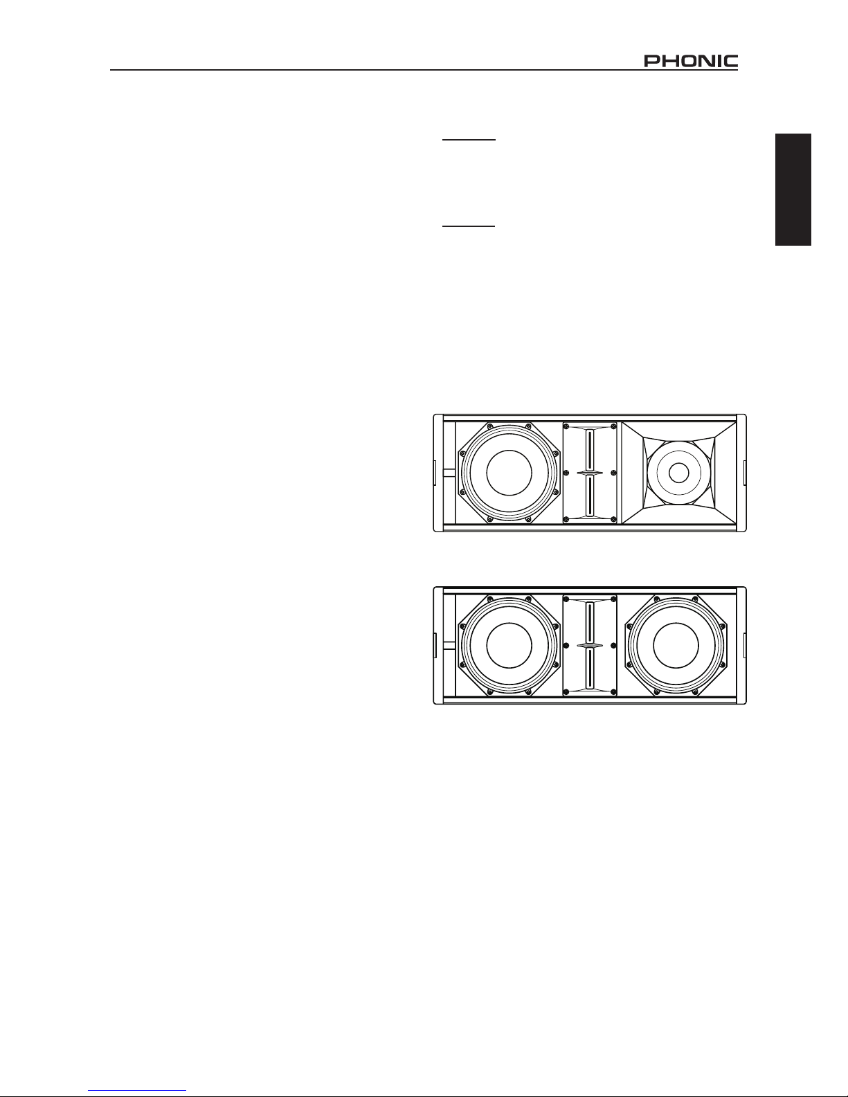
KT-8A
48” bass-loaded woofer, 6.5” mid-range woofer with
2” voice-coils
4860 Watt multichannel digital power amplier
4Maximum sound pressure level: 129 dB
4120° horizontal, 10° vertical dispersion pattern
4Exceptionally wide frequency response: 70Hz to
19KHz (-3dB)
4Bass-reex conguration for extended low-end
response
KT-210A
4Two 10” woofers with 2” voice-coils
41500 Watt dual channel digital power amplier
4Titanium diaphragm compression driver
4Maximum Sound Pressure Level: 132dB (Peak)
4Can be mounted in conjunction with the KTS-18/
KTS-18A subwoofer
4Frequency response: 65Hz to 19KHz (-3dB)
4110° horizontal, 10° vertical dispersion pattern
Common Features:
4 Two 1.4” titanium diaphragm tweeters matched
with neodymium magnets
4Straightforward rigging system allows splay
angles from 0° to 10°
4Made of sturdy, multi-layer birch plywood with
tough black coating
4XLR input and link ‘thru’ connectors as standard
4 PowerCON AC power input/output
ACCESSORIES
Included
U-Clip / Shackle
Flight Pins
Optional
KT-8A Mounting Frame Model # FF640 (640mm)
KT-210A Mounting Frame Model # FF760 (760mm)
CONFIGURATION
The KT-8A’s tri-amp system provides three amplier
channels to drive each of the individual drivers. The
low-range amplier provide 400 Watts of power to
the woofer, the mid-range amp provide 300 Watts to
the 6.5” speaker and the tweeter receives 160 Watts.
Similarly, the KT-210A features a bi-amp design that
provides 1200 Watts to the woofers and 300 Watts
to the tweeters.
These congurations guarantee greater sound delity, higher dynamism and a signicant increase in
sound pressure.
Page 6
2
KT-8A / KT-210A
English
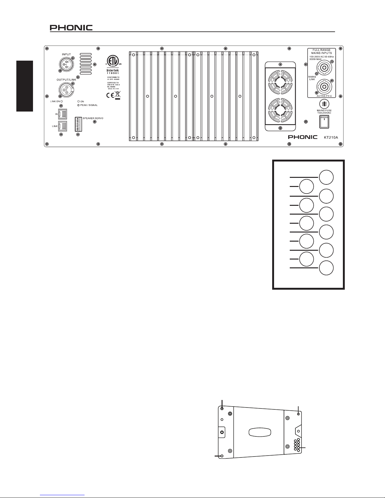
CONNECTORS
The KT-8A and KT-210A feature balanced XLR input
connection in addition to an XLR output/link connector. This is shown on the top left-hand side of the rear
panel image above.
In addition to this, the speaker features two RJ-45
connectors for utilizing the onboard CPU. By connecting the “LINK” port on one unit to the “IN” port
of another, you’re essentially creating a network of
the KT models.
The MAINS INPUT connections allow power to be
applied to the KT-8A and KT-210A systems. The
systems are powered by the uppermost connection,
while the lower connection (labelled “MAINS LINK”)
is used to link to power additional units.
FUSE & POWER
Below the power connectors you can nd a FUSE
holder and main power switch. The power switch can
be defeated within the KT series Windows software.
In the event that the power won’t turn on, ensure that
the power switch is activate within the PC software. If
it is and power will still not turn on, check the system’s
fuse has not blown.
DIP SWITCHES
DIP switches 1 to 5 of the KT series allow users to
establish the ID of the unit. Each unit must have an
independent ID for the KT series software to recognize the product within your network.
DIP 8 being set to ON will enable ‘Initialization Mode’
for the KT-8A or KT-210A. When in this mode, the sys-
tem can be restored and/or new rmware installed.
FANS
Two variable speed fans can be found on the rear of
the KT-8A and KT-210A. These work in conjunction
with the internal temperature control to ensure the
speaker runs cool. Please do not obstruct the fans
for any reason as doing so can be detrimental to the
speaker’s performance and reliability.
10°
9°
8°
7°
6°
5°
4°
3°
2°
1°
0°
PIN HOLE
JOINT BAR
PIN HOLES
JOINT BAR
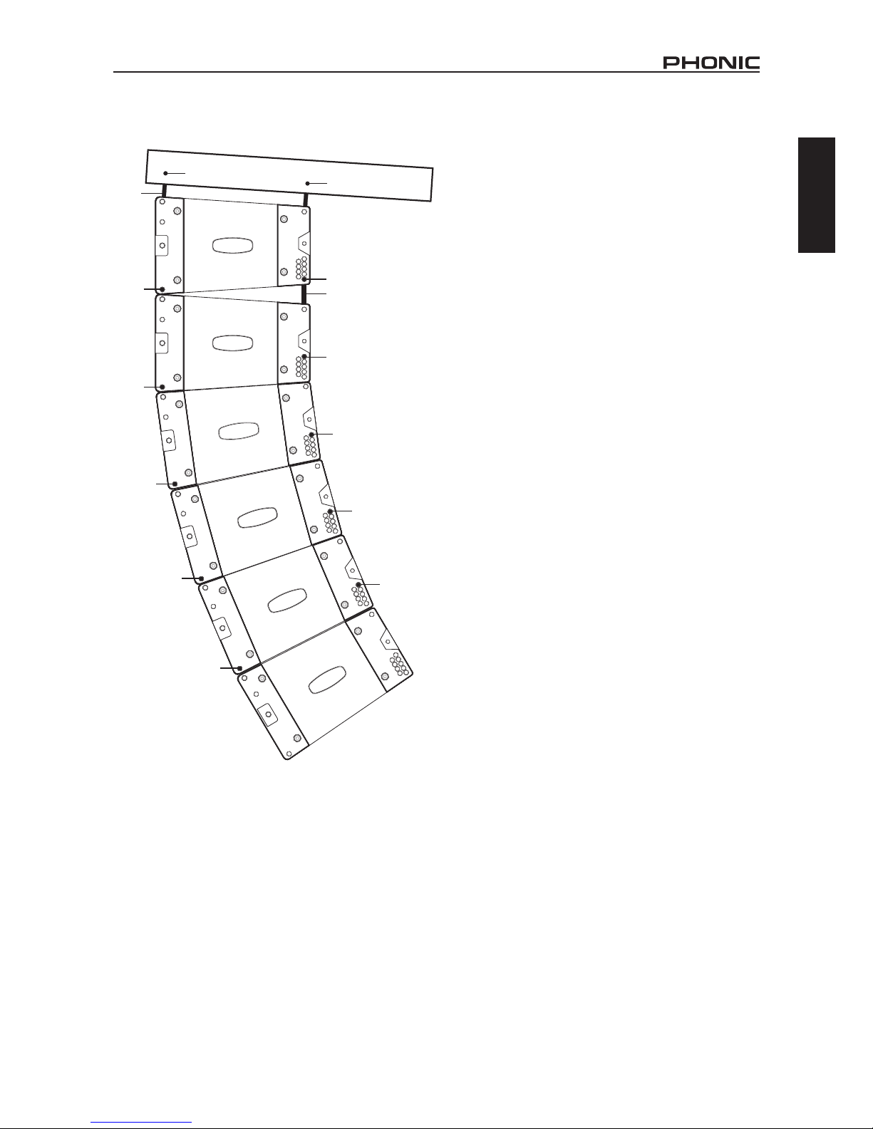
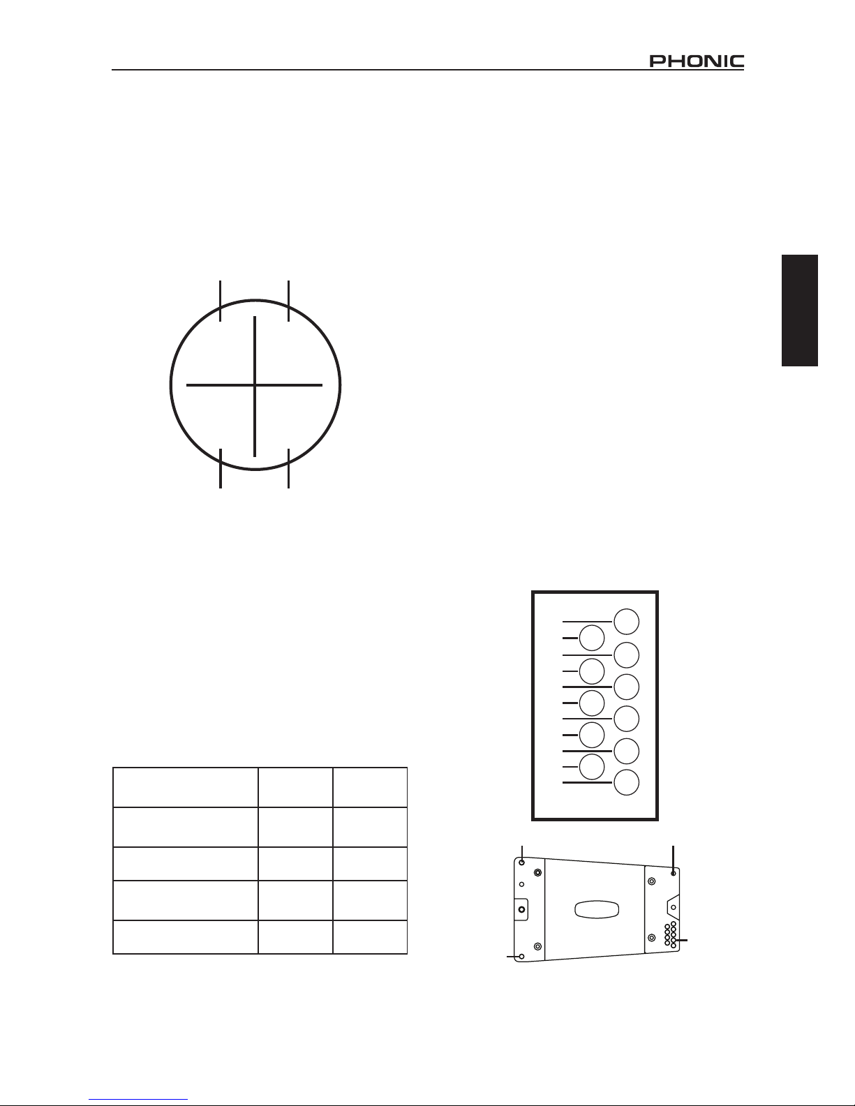
ASSEMBLY
The array conguration is
accomplished through a
simple ‘pin-in-hole’ method
of connection. The top
corners of the KT-8A and
KT-210A each feature a
retractable joint bar. These
extend to be inserted into
each of the four slots at
the bottom of the next unit
in the array. The four ight
pins chained to the unit can
be inserted in the appropri-
ate holes to x the units
together.
The ight pins have a but-
ton on the end that can
be pushed to release the
pin’s latch. This should be
pushed when inserting the
pin into the mounting holes.
The pins should sit ush with the side of the unit and
be unable to wiggle within the frame. To accomplish
this, the pin must be inserted completely through the
mounting holes on both of the KT units being joined
in the array; through the outer-hole on the lower-part
of one unit, through the second unit’s joint bar, and
again through the rst unit’s inner-hole.
The lower-front corner of each unit features a single
mounting hole, while the lower-rear corner offers 11
individual holes that will determine the angle between
the two units. Connecting two units at 0° will create
narrower, yet more focused, dispersion. At 10° the
array will create a much wider vertical dispersion.
Page 7
3
KT-8A / KT-210A
English
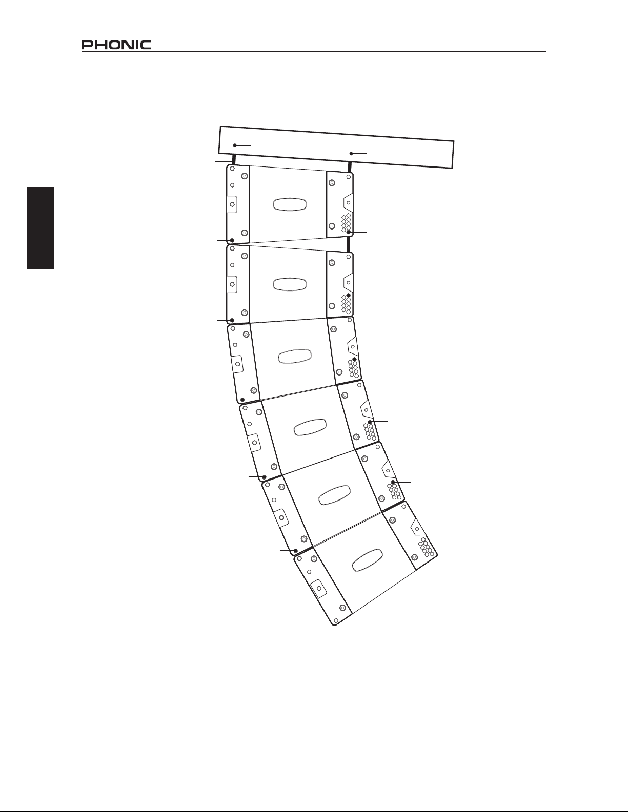
FLIGHT PIN
FLIGHT FRAME
(MODEL # FF640)
FLIGHT PIN
FLIGHT PIN
FLIGHT PIN
FLIGHT PIN
FLIGHT PIN
FLIGHT PIN
FLIGHT PIN
FLIGHT PIN
JOINT BAR
JOINT
BAR
0°
10°
FLIGHT PIN
10°
FLIGHT PIN
10°
FLIGHT PIN
10°
SUGGESTED CONFIGURATION
Page 8

4
KT-8A / KT-210A
English
BASIC SETUP
Making Connections
1. First and foremost, make sure the KT series is
turned off and unplugged before making any
connections.
2. Once you ensure the KT line array is off, you can
make your input and output connections. Connect
the main output of your mixer to the input of the
rst KT model in your array. The output connector
on that speaker should be connected to the input
of the next speaker, and so on.
3. The Ethernet connection of your computer or
network should be connected to the ‘IN’ Ethernet
port on the speaker. The ‘LINK’ port should be
connected to the ‘IN’ port of the next speaker, and
so on.
4. Using the included power cable, the ‘MAINS
INPUT’ connection should be connected to an
appropriate power supply. The ‘LINK’ connectors
should be connected to the ‘MAINS INPUT’ on the
next speaker. Continue this chain to power each
speaker in the array. Power on the electrical outlet
that the rst speaker is connected to ensuring it is
of a suitable voltage for the KT speaker.
Software Setup
5. Open the Windows software. Click the “Search
Device” button found at the top of the software.
This will seek KT line array units in your network.
6. Once an appropriate COM PORT is found, click
“Connect”. Once the KT is “Online”, it will appear
within the software. You can double-click the
image to use the software’s control functions.
7. It should be noted that power to the KT line array
speakers is not activated by default. To activate
the speakers, you will need to click ‘Online’ under
S/W Power in the Setup menu. Please note you
can also deactivate the physical power switch in
this menu.
FIRMWARE UPDATE
The latest rmware for the KT series line arrays can
always be found on www.phonic.com. To perform a
rmware update, ensure the speaker is connected
to the network and online. DIP switch 8 on the rear
of the system must also be set to “ON” in order to
receive the new rmware.
1. Select the Update pulldown menu and select
“Firmware Update.”
2. Locate the update le in your Download folder (or
wherever you saved the rmware update).
3. Select the “Update” button to update the rmware
on your KT-8A or KT-210A.
SAFETY CONSIDERATIONS
Please read all safety instructions found opposite
page 1 of this section of the manual.
KT-8 line array speakers should only be installed
by experienced personnel with adequate knowledge. Phonic takes no responsibility for incorrectly
mounted, suspended, or wired speakers, nor are we
responsible for issues arising from equipment not
inspected prior to use.
When working with the KT-8 line array systems, the
total working load should not exceed the resistance
of each individual component. This includes ight
pins, joint bars, ight frames and speaker cabinets.
While the Phonic ight frame and KT-8 speakers
have a maximum capacity of 1000 kg, consideration
of other elements of the setup should be taken into
consideration. This may including hoisting ropes and
other suspension materials.
Phonic suggests a safety ratio of 5:1. With this in
mind, a total load of 200 kg should be the aim when
creating your line array using the KT-8A or KT-210A
and the appropriate Phonic ight frame. As previously
stated, however, the total resistance of other components of the setup should be taken into account.
DO NOT ATTEMPT TO CARRY A LINE-ARRAY.
Under no circumstances should you attempt to lift a
line array by yourself. Mechanical winches and other
hoisting devices are recommended.
The KT-8A and KT-210A are equipped with internal
crossovers for mid/highs. There is no crossover present on the woofer. Please note that incorrectly wired
speakers may cause damage to the unit.
Phonic recommends taking the utmost of care
when wiring and/or connecting speakers. A 2-way
crossover with a crossover point at 500Hz is best to
separate low frequencies from the mid/highs. The
ideal frequency range for the KT-8A’s 8” woofer is
60Hz to 500Hz, while the mid/high range works best
at 500Hz to 20 kHz.
SOFTWARE INSTALLATION
The KT Windows software needs to be installed to
your system before it can be utilized by the KT line
arrays. Installation is fairly simple.
1. Insert the included CD into your computer’s CDROM drive and close the tray.
2. Navigate the disc to nd the “setup.exe” le. Run
in by either double-clicking the le or by rightclicking the le and select “Run as Administrator”.
3. Follow the installation instructions.
4. After installation is complete, the KT software can
be run by running the appropriate software icon.
Page 9
5
KT-8A / KT-210A
English
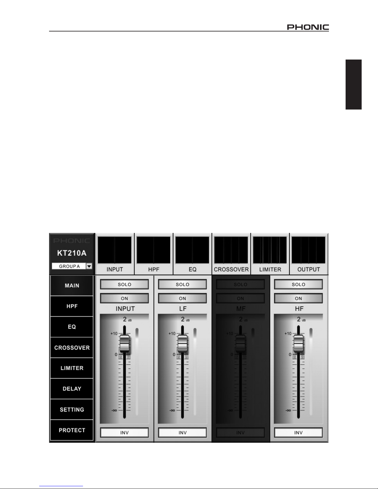
MAIN
The “Main” menu in the KT Windows software provides a number of controls for each of the frequency
ranges provided within the software.
SOLO BUTTON: This will solo the corresponding
mix, whether it’s the INPUT mix or the HF, LF or
MF. When a signal is soloed, all others will mute.
This includes all other speakers connected to your
network. This feature is useful for helping to detect
faults in speakers while suspended. If you “SOLO” the
“INPUT” of the speaker suspected of being at fault,
all others will mute and you can demo the speaker
individually and rule it out as the cause.
ON BUTTON: The on button simply turns the corresponding frequency range on and off. Turning the
“INPUT” off will effectively mute the speaker, while
turning off the “LF” (low frequency), “MF” (middle
frequency) or “HF” (high frequency) controls will cut
off their respective frequency ranges. Please note
that the KT-210A only features HF and LF while the
KT-8A features HF, MF and LF.
LEVEL CONTROL: The main menu features a “virtual fader” that can be adjusted by simply dragging
the fader up and down using your mouse. Click the
fader and move the mouse up or down to adjust.
LEVEL METER: Each of the individual level controls
also features a level meter located directly beside it.
When levels are obviously excessive, Phonic advises
reducing them to reduce the risk of distortion.
INVERT PHASE: Immediately below the level control and meter is an invert phase button. This will
immediately invert the phase of the incoming signal,
whether it’s the “input” signal, or the low, mid, or high
frequencies.
Page 10
6
KT-8A / KT-210A
English
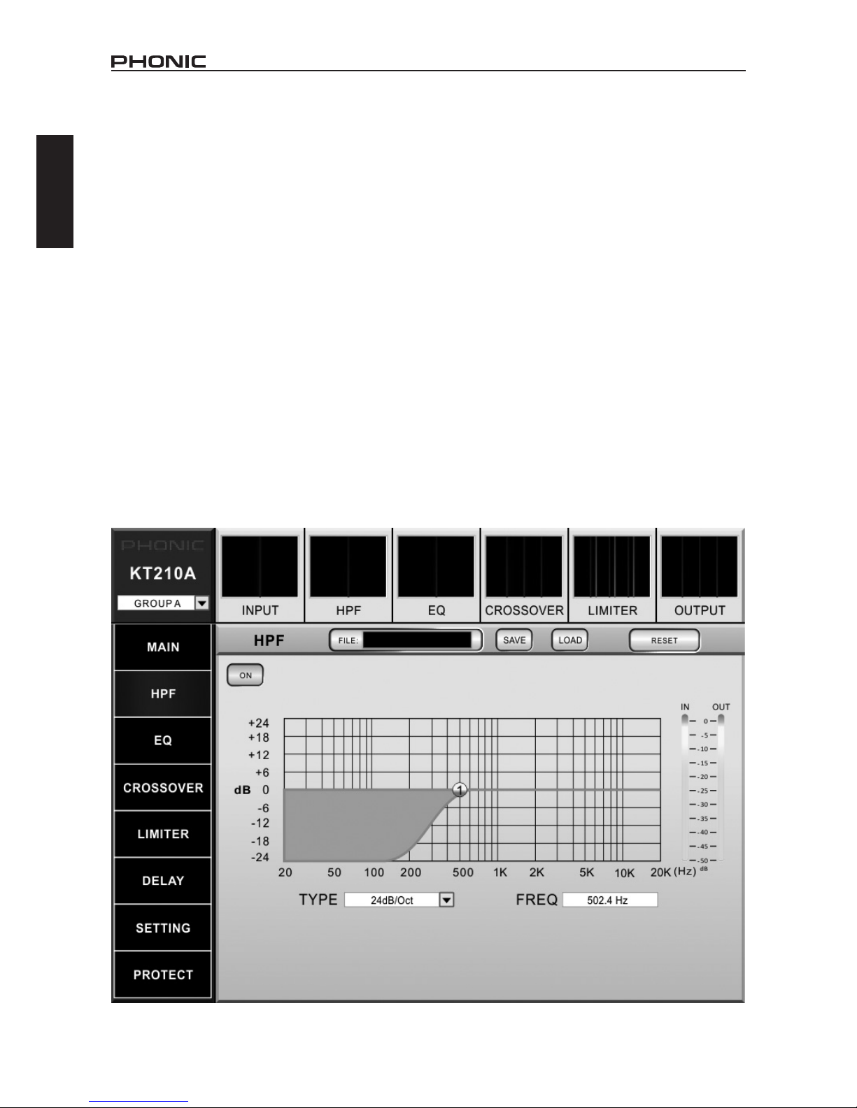
HPF
The KT software features a simple high-pass lter
(HPF) to effectively remove low-frequency audio from
your main signal. This can effectively remove stage
rumble and other low-frequency interference that
could ruin an otherwise perfect performance. It also
allows the KT’s internal amplier to concentrate more
on actual program and ignore this low-frequency
audio.
ON BUTTON: The on button simply turns the HPF
on and off.
DISPLAY GRAPH: The HPF can be adjusted within
the display graph. The small icon can be dragged left
or right to adjust the cut-off frequency for the HPF.
TYPE: The type of lter can be adjusted with this
pull-down menu. The default setting for this is 24dB/
Oct but other slopes are available.
FREQUENCY: The frequency is displayed within this
window located beside the TYPE pull-down menu.
The frequency is adjusted using the icon within the
display graph and can be set anywhere between
20Hz and 20kHz.
FILE: The le window will display the currently loaded
preset for the HPF. This can be selected by pushing
the LOAD button.
SAVE: Push the save button to save the current
settings of the HPF. These are saved locally on the
computer and can be recalled at a later time.
LOAD: Selecting load will allow you to recall any of
the previously saved HPF settings.
RESET: The reset button will return the HPF back to
its default settings.
Page 11

7
KT-8A / KT-210A
English
GRAPHIC EQUALIZER
The KT software includes two types of equalizers that
can be utilized. The rst is a 31-band GEQ with an
adjustable Q, while the second is a 10-band para-
metric equalizer with adjustable type, gain, frequency
and Q. The equalizer can be utilized
ON BUTTON: The on button simply turns the 31-
band GEQ on and off.
FUNCTION: The function button will allow you to
select whether the EQ is a 31-band GEQ or 10-band
PEQ.
DISPLAY GRAPH: This plotted graph allows you
to view the curve created by the graphic equalizer.
METER: Located beside the display graph, these
level meters provides up-to-the-second information
on your GEQ’s signal input and output levels.
GEQ BANDS: Each of the 31 bands can be adjusted
here. Frequencies available range between 20Hz
and 20kHz. Simply click the virtual control and drag
it up or down to adjust. The adjustment made will be
visible within the display graph.
Q CONTROL: This adjusts the ‘width’ of the bands of
the 31-band GEQ. Use the left mouse button to lower
the value or the right button to increase the value.
FILE: The le window will display the currently loaded
preset for the EQ. This can be selected by pushing
the LOAD button.
SAVE: Push the save button to save the current
settings of the EQ. These are saved locally on the
computer and can be recalled at a later time.
LOAD: Selecting load will allow you to recall any of
the previously saved EQ settings.
RESET: The reset button will return the EQ back to
its default settings.
Page 12

8
KT-8A / KT-210A
English
PARAMETRIC EQUALIZER
The KT software also includes a 10-band parametric
equalizer that can be utilized instead of the 31-band
graphic equalizer. Simply select the appropriate func-
tion button to activate the 10-band PEQ.
ON BUTTON: This simply turns the PEQ on and off.
FUNCTION: The function button will allow you to
select whether to use the PEQ or GEQ.
DISPLAY GRAPH: This plotted graph allows you to
view the curve created by the graphic equalizer. Each
of the EQ bands can simply be dragged (using the
mouse) to adjust the frequency and level.
METER: Located beside the display graph, these
level meters provides up-to-the-second information
on your PEQ’s signal input and output levels.
PEQ ON/OFF BUTTONS: Each of the 10 bands has
its own independent on/off buttons. When turned off,
the corresponding band will no longer appear in the
display graph.
TYPE: This determines the type of of band used. A
“PEAK” band will simply peak at the selected frequency/level, while a “SHELF” will level off at the selected
frequency. A “HIGH CUT” or “LOW CUT” will remove
all frequencies above/below the selected frequency.
GAIN/FREQUENCY/Q: The gain, frequency and Q
can be adjusted within these windows. The gain and
frequency can easily be adjusted within the display
graph by moving individual points, however all three
can also be edited here. Push the left mouse button
to reduce the values and the right mouse button to
increase.
FILE: The le window will display the currently loaded
preset for the EQ. This can be selected by pushing
the LOAD button.
SAVE: Push the save button to save the current
settings of the EQ. These are saved locally on the
computer and can be recalled at a later time.
LOAD: Selecting load will allow you to recall any of
the previously saved EQ settings.
RESET: The reset button will return the EQ back to
its default settings.
Page 13
9
KT-8A / KT-210A
English
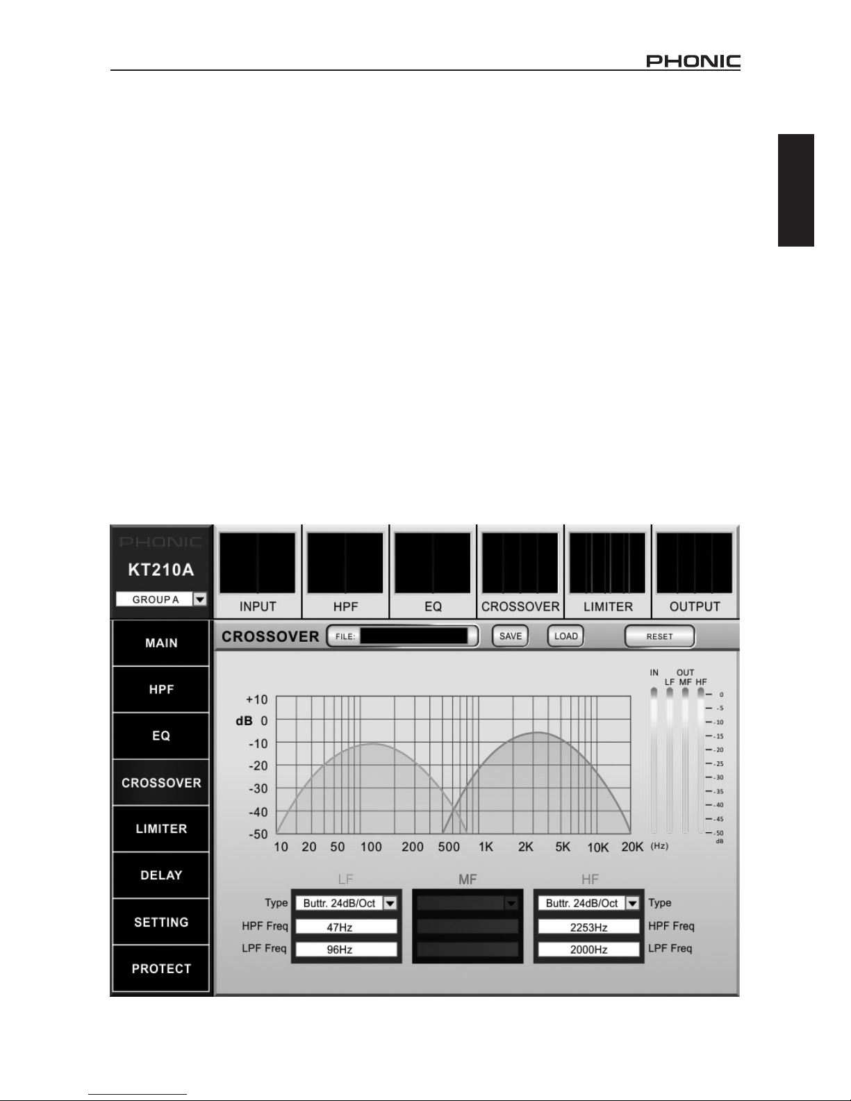
CROSSOVER
Both the KT-8A and KT-210A have an internal crossover. This essentially separates the high, mid and low
frequency audio from your main signal to be sent to
their respective speakers. LF is sent to woofers, MF
is sent to mid-ranges and the HF is sent to tweeters. The KT-8A includes a three-way crossover (LF,
MF, HF) while the KT-210 has a two-way crossover
(LF, HF).
TYPE: This determines the type of crossover the KT
series will use. The default setting for this is a 24dB/
octave butterworth but a number of other types and
curves are available.
DISPLAY GRAPH: This will show the properties of
your crossover, including frequencies, levels and the
selected curve.
HIGH PASS FILTER (HPF) FREQUENCY: This eld
determines the cut-off frequency of the corresponding
crossover’s HPF. Frequencies below this point will be
removed at a predetermined rate. The rate at which
the frequencies below this point are cut is dependent
on the selected “type”.
LOW PASS FILTER (LPF) FREQUENCY: This eld
determines the cut-off frequency of the corresponding
crossover’s LFP. Frequencies above this point will be
removed at a predetermined rate. The rate at which
the frequencies below this point are cut is dependent
on the selected “type”.
METER: These meters show the KT crossover’s input
and output levels. As this is a crossover, there are
independent level meters for each the low frequency,
mid frequency and high frequency outputs.
FILE: The le window will display the currently loaded
preset for the CROSSOVER. This can be selected
by pushing the LOAD button.
SAVE: Push the save button to save the current settings of the CROSSOVER. These are saved locally
on the computer and can be recalled at a later time.
LOAD: Selecting load will allow you to recall any of
the previously saved CROSSOVER settings.
RESET: The reset button will return the CROSSOVER back to its default settings.
Page 14
10
KT-8A / KT-210A
English
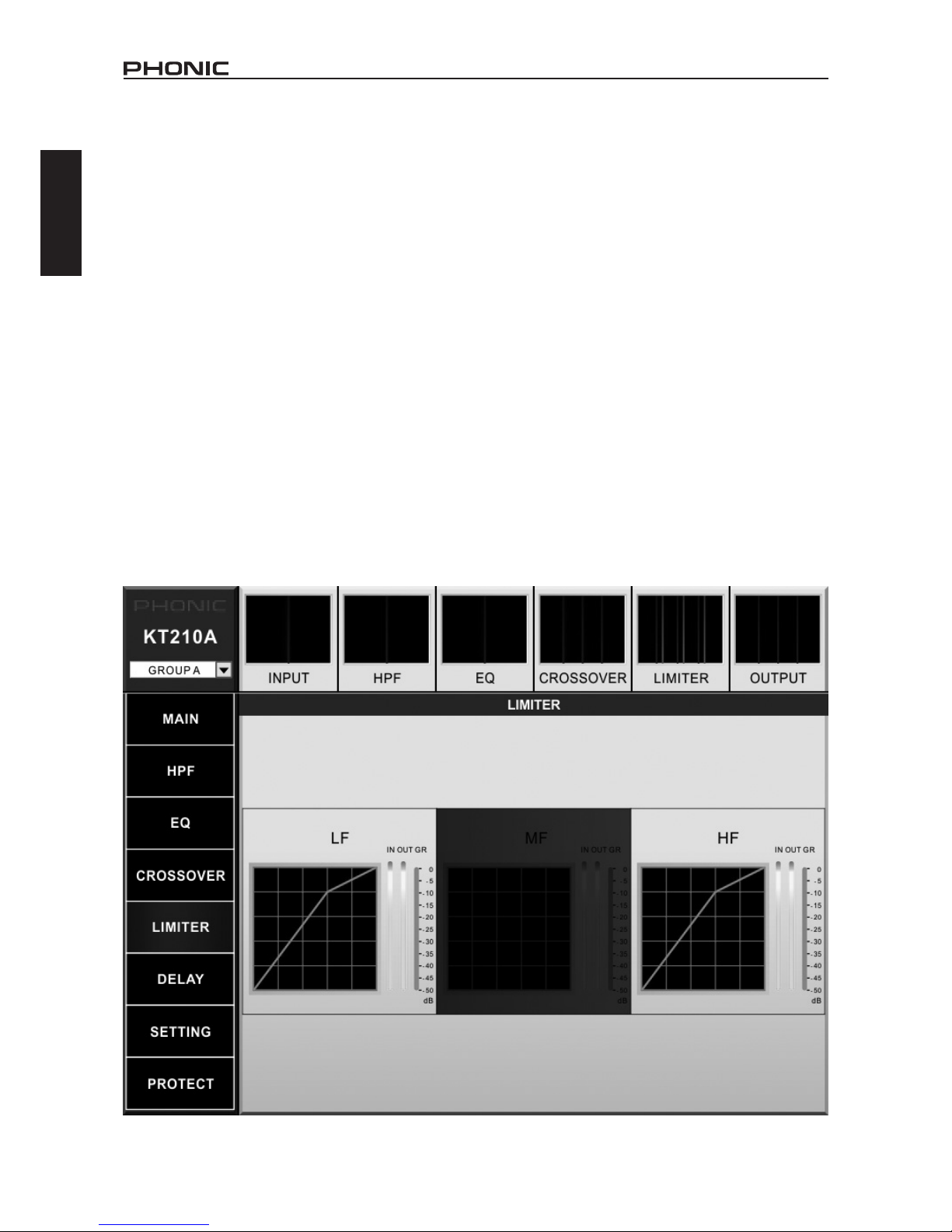
LIMITER
The KT series software includes a compressor/limiter
for each the high, mid and low-frequency audio. A
compressor essentially reduces excessive levels by
a pre-determined ratio. Once the output signal surpasses a user-set level, the signal over this level will
be ‘compressed’ at the user-determined ratio. Once
the signal then reaches the “limiter” threshold set by
the user, it will be cut off at that level. Essentially, the
signal level will not surpass the limiter’s threshold.
The rst page of the LIMITER section of the KT
software simply has display graphs for each the lowfrequency, mid-frequency and high-frequency. Users
can simply select these on screen to enter the limiter
for that particular frequency range.
In addition to the graph displaying the compressor/
limiter curve, these windows also include input and
output meters and a gain reduction meter. The gain
reduction meter will display the level that the signal
is reduced when the compressor and limiter are
activated.
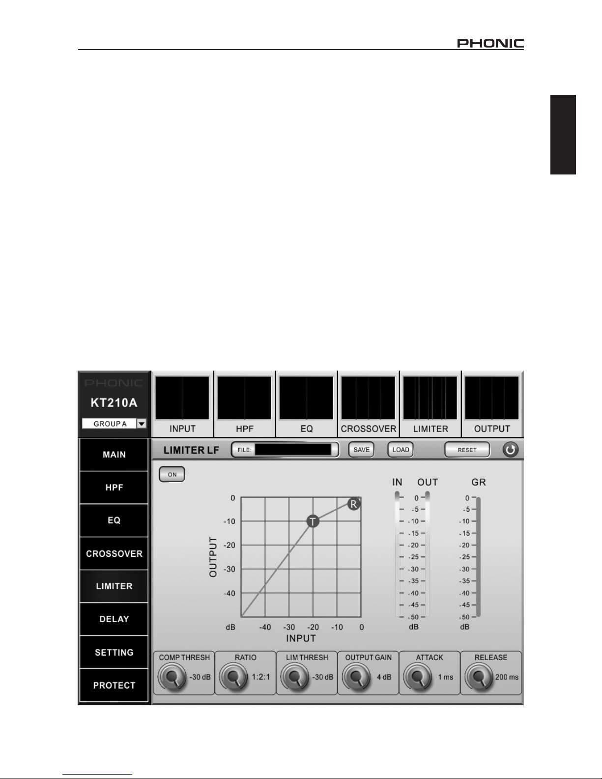
LIMITER LF / MF / HF
ON BUTTON: The on button will simply activate and
deactivate the corresponding limiter.
DISPLAY GRAPH: This plots the input/output levels of the compressor and limiter. The individual
threshold (T) and ratio (R) for the compressor can be
adjusted on screen by simply clicking and dragging
the points with your mouse.
LEVEL METER: Directly beside the display graph
is an input and output meter. If output levels are
excessive, the limiter can actually be utilized to help
combat this.
GAIN REDUCTION: This meter will display the level
in which the limiter reduces the output signal.
COMPRESSOR THRESHOLD: This adjusts the
threshold of the compressor. Once your signal level
passes the selected threshold, the compressor will
kick-in at the set ratio.
RATIO: This can be used to adjust the compressor
input/output signal ratio. This essentially determines
the level at which the signal will be cut after the
threshold is surpassed.
Page 15
11
KT-8A / KT-210A
English
LIMITER THRESHOLD: This adjusts the threshold
of the limiter function. This works in conjunction with
the compressor. A limiter could be seen simply as a
compressor with an ∞:1 ratio.
OUTPUT GAIN: Increases the nal output level of
the compressor/limiter.
ATTACK CONTROL: The attack control adjusts the
time it will take for the compressor/limiter to kick in
after the signal rises above the set threshold.
RELEASE CONTROL: The release control adjusts
the time it will take for the compressor/limiter to deactivate after the signal falls below the set threshold.
FILE: The le window will display the currently loaded
preset for the LIMITER. This can be selected by
pushing the LOAD button.
SAVE: Push the save button to save the current settings of the LIMITER. These are saved locally on the
computer and can be recalled at a later time.
LOAD: Selecting load will allow you to recall any of
the previously saved LIMITER settings.
RESET: The reset button will return the LIMITER
back to its default settings.
RETURN BUTTON: Clicking the circular button with
an arrow will return the user to the rst page of the
limiter function.
Page 16
12
KT-8A / KT-210A
English
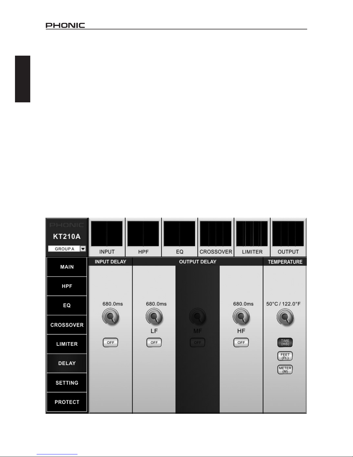
DELAY
Both the KT-8A and KT-210A feature a delay function.
An output delay can be applied to the entire speaker
or individual frequency outputs (high, mid and low).
Adding a delay to an entire speaker array can help to
compensate for distance between speakers in large
multi-speaker setups. A delay time of one millisecond
per foot (or 3 milliseconds per meter) that the speaker
is away from the stage is the general rule of thumb
in this application. This, however, is not always the
case. Thankfully, the KT Network System allows the
delay time to be set in “meters” or “feet” instead of
“milliseconds”, taking a lot of the guesswork out of
the setup.
DELAY CONTROLS: These controls adjust the total
delay time that would be added to their respective
channels (input delay, low frequency, mid frequency
or high frequency). The delay time can be adjusted
in milliseconds, meters and feet.
ON BUTTONS: The on buttons quite simply activate
the delay function of the corresponding channel.
TEMPERATURE: The temperature option allows the
user to set the ambient temperature of the current
venue. This allows the KT Network System to calculate a more accurate delay-time when set in “feet”
or “meters”. In addition to the temperature control,
this section of the Delay function offers “time (ms)”,
“feet” and “meter” buttons, changing the adjustable
delay between these parameters.
PARAMETER BUTTONS: Found on the bottom
right-hand side of the KT Network System software,
these three buttons allow users to select the parameter adjusted by the delay controls. Selecting “TIME”
will allow the delay to be adjusted in milliseconds
(recommended for experienced users), while “FEET”
and “METERS” will allow the delay to be adjusted
according to distance. When adjusting the delay by
distance, Phonic recommends using the distance
between the KT line array speaker and the front-ofhouse speakers.
Page 17
13
KT-8A / KT-210A
English
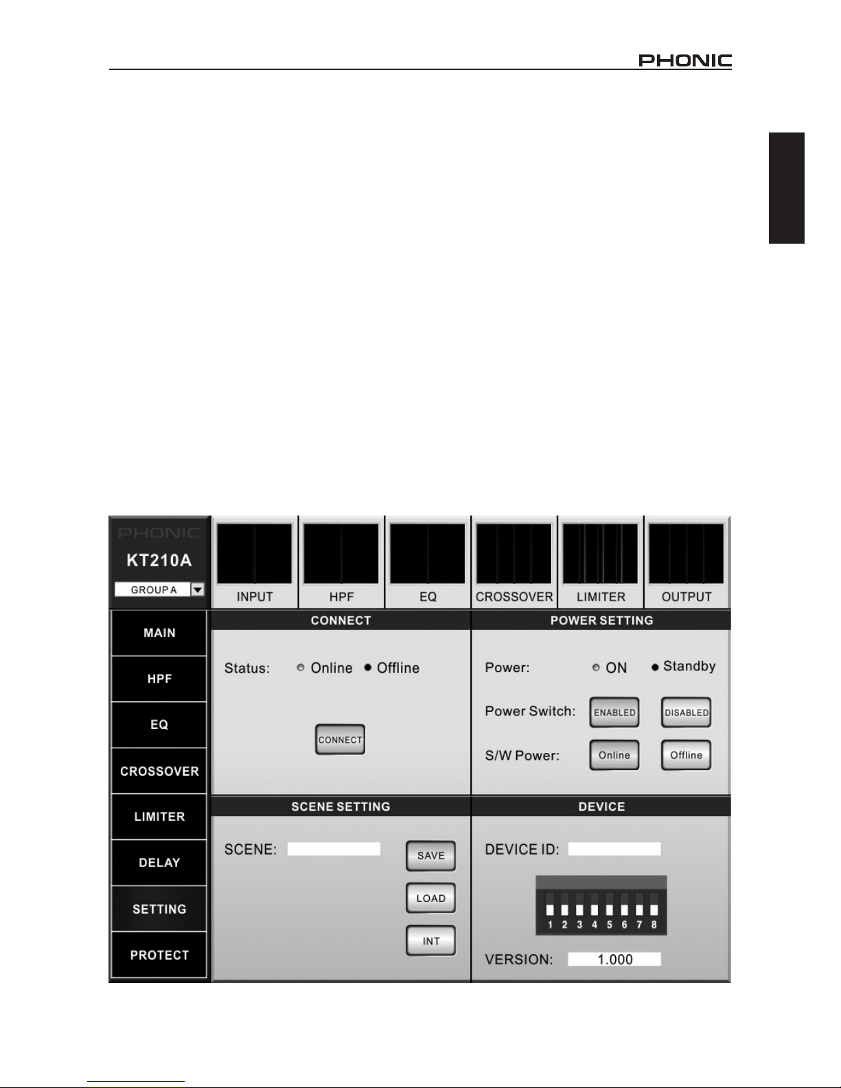
SETTING
The setting menu includes a number of properties
that can be adjusted, including connection and power
settings.
CONNECT: The connect window within the setting
menu simple provides the status of the currently
selected KT speaker. When “Online”, it means a
connection was successfully established between
the speaker and the software. The “Connect” button
should be pushed to establish a connection.
POWER SETTINGS: The power settings provide
indicators for the current status of the selected KT
speaker. “ON” indicates that the speaker is activated
while “Standby” means there is currently no sound
from the speaker but it is in standby. The status of
the KT speaker can be adjusted by the “S/W Power”
buttons. “Online” will activate the speaker while “Of-
ine” will put the speaker in standby mode. The power
switch can be de-activated by the “Power Switch”
option. Essentially the disable button will allow you to
bypass the hardwired power switch on the currently
selected KT speaker.
SCENE SETTINGS: The scene feature essentially
allows you to save all of your settings, including your
MAIN, HPF, EQ, CROSSOVER, LIMITER and DELAY
settings. The currently selected SCENE name will
be displayed in the scene window. The SAVE button
will allow you to save your scenes while the LOAD
button will let you load up a previous saved scene.
The “INT” button will initialize the system, basically
resetting all functions back to their factory presets.
When requiring identical settings on multiple speakers within the array, Phonic suggests saving the
scene after everything is set, then reloading these
scenes on all subsequent speakers. This will save
valuable setup time.
DEVICE: The device ID will be displayed within this
window, as set by the KT series’ DIP switches located
on the bottom of the unit. Please note that every device connected to your KT Network System software
should have its own unique Device ID. This allows
the software to correctly identify each independent
speaker.
Directly below this setting, the current rmware version of the system can be found. Please remember,
the latest rmware for your KT speakers can be found
on www.phonic.com.
Page 18
14
KT-8A / KT-210A
English
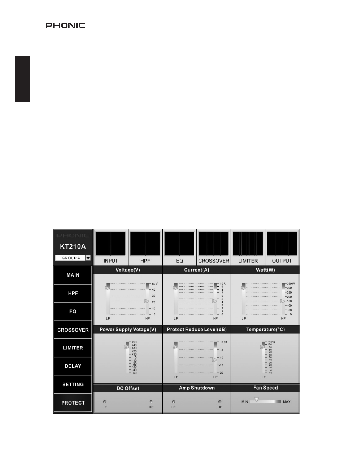
PROTECTION CIRCUITRY
The KT series line array speakers feature a number
of protection mechanisms in place to ensure no damage occurs to the speakers. This page offers clear,
concise monitoring of many aspects of the KT series.
VOLTAGE METER (V): This shows the voltage
that the amplier is delivering. This helps determine
whether a channel is currently sending high voltage
levels.
CURRENT METER (A): This shows the current that
the amplier is delivering to a load in amps. This is
useful in determining if a speaker load is open or
shorted.
WATT METER (W): This shows the power level in
Watts that the amplier is delivering to speakers. This
can be helpful in determining whether speakers are
receiving adequate power or if they can handle more.
The levels will reduce by 0.5 dB every 6 seconds
and return to normal levels at the same rate once
the issue has been resolved.
POWER SUPPLY VOLTAGE (V): This indicates the
+/- voltage provided to channel groups (1 to 4 and 5
to 8). When the supply voltage exceeds +/- 20%, the
power is automatically turned off. When the supply
voltage returns within +/- 20%, the power is automatically activated.
CHANNEL REDUCE LEVEL (dB): These individual
meters give an indication of when protection circuitry
has kicked in and input levels have been reduced to
compensate.
TEMPERATURE (°C): This meter displays the internal temperature of each channel. Temperatures in
excess of 100°C will trigger the protection circuitry.
DC OFFSET: This indicates if the DC offset protection
was triggered on any channel (LF, HF and/or HF).
AMP SHUTDOWN: These indicators show when an
amplier channel has shutdown. This could be in
response to excessive heat, or potentially overcurrent protection.
FAN SPEED: This meter gives an up-to-the-minute
indication of the speed of the internal fan. When the
speed hits maximum, over-temperature protection
may kick in as a response. We suggest manually
reducing levels to help avoid this occurring.
Page 19
15
KT-8A / KT-210A
English
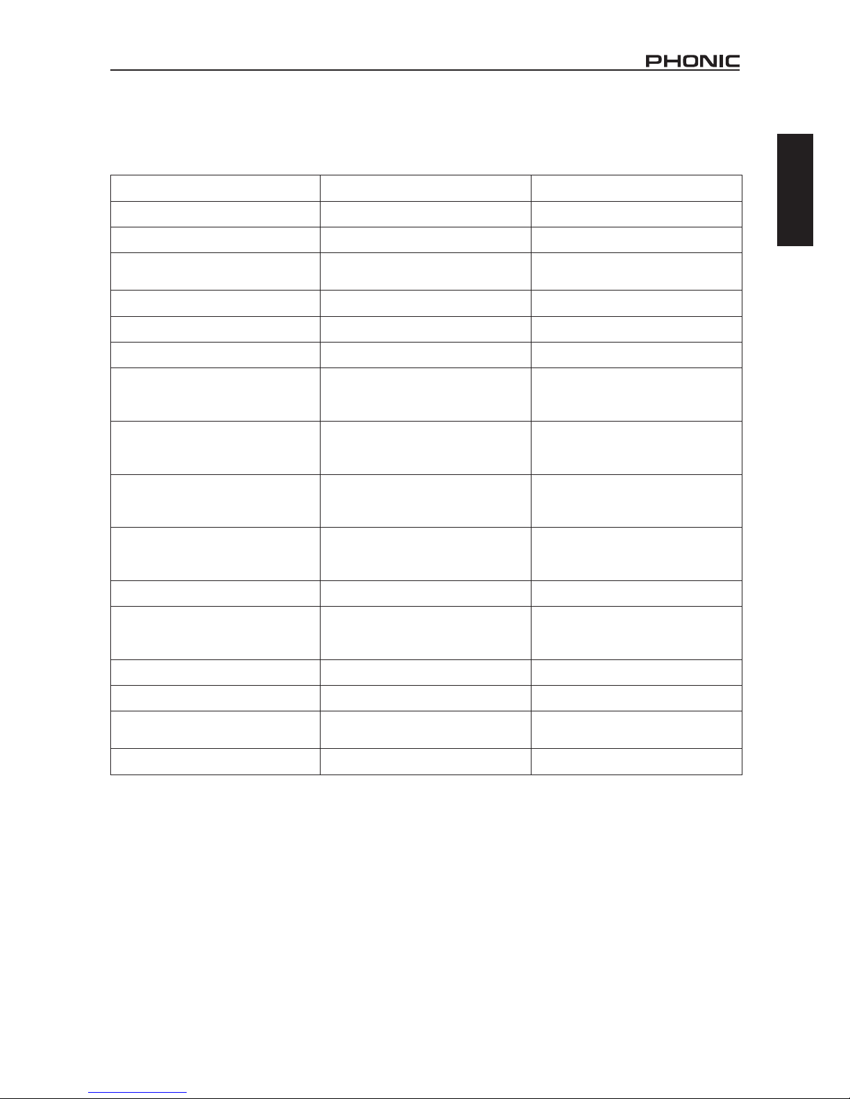
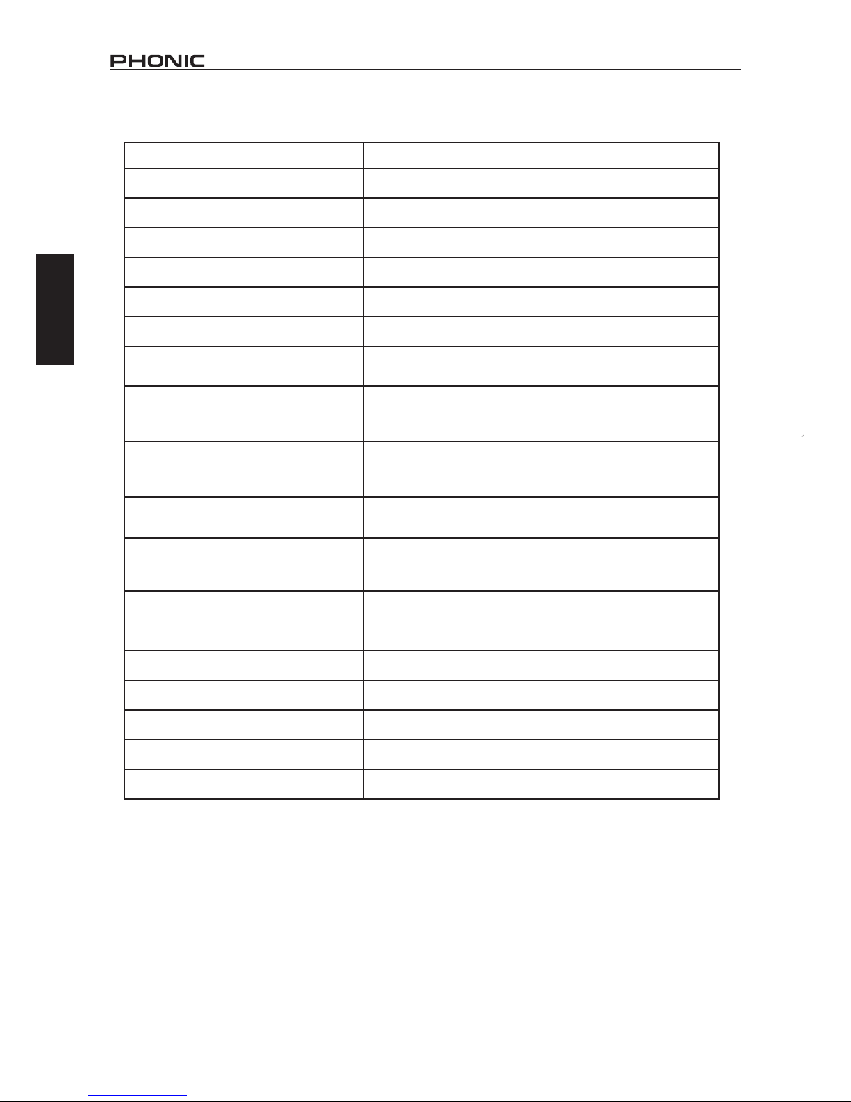
SPECIFICATIONS
KT-8A KT-210A
Woofers 8" 2 x 10"
Mid-range 6.5" -
Tweeter
Two 1.4" titanium diaphragm
compression driver
1.4" titanium diaphragm
compression driver
Frequency Range (-3dB) 70Hz - 19KHz 65Hz - 19KHz
Horizontal Coverage 120° 110°
Vertical Coverage 10° 10°
Nominal Amplier Power
LF: 420 Watts
MF: 320 Watts
HF: 160 Watts
LF: 1200 Watts
HF: 300 Watts
On-Axis SPL 1W/1m
LF: 96 dB
MF: 102 dB
HF: 105 dB
LF: 98 dB
HF: 113 dB
Rated Maximum Peak SPL at 1m
LF: 126 dB
MF: 129 dB
HF: 129 dB
LF: 132 dB
HF: 137 dB
Enclosure Material
18mm multi-layer birch plywood,
8mm hexagonal black steel mesh
with special accoustical foam
15mm multi-layer birch plywood,
8mm hexagonal black steel mesh
Color Black Black
Rigging System
Included ight pin
and u-clip/shackle
Optional grid assembly/ight frame
Included ight pin
and u-clip/shackle
Optional grid assembly/ight frame
Input & Output Connectors 2 x XLR 2 x XLR
Power Connectors 2 x PowerCON 2 x PowerCON
Dimensions (HxWxD)
270 x 580 x 400 mm
(10.6" x 22.8" x 15.7")
300 x 760 x 460 mm
(11.8" x 29.9" x 18.1")
Weight 25 kg (55.1 lbs)
Page 20

16
KT-8A / KT-210A
English Español
CONTENIDO
Manual del Usuario
Phonic se reserva el derecho de mejorar o alterar cualquier información
provista dentro de este documento sin previo aviso.
INTRODUCCIÓN 1
CARACTERÍSTICAS 1
ACCESORIOS 1
CONFIGURACIÓN 1
CONECTORES 1
CABLEADO....................................................................................2
MONTAJE..........................................................................2
CONFIGURACIÓN SUGERIDA.............................................3
CONSIDERACIONES DE SEGURIDAD 4
ESPECIFICACIONES 5
APÉNDICE
APLICACIONES 1
DIMENSIONES 2
Page 21
17
KT-8A / KT-210A
English Español
La instalación debe ser realizada por un personal
cualificado y experimentado.
Una Inspección de materiales colgantes debe ser
realizada antes de cada uso para evitar accidentes.
Asegurarse de que todos los dispositivos de bloqueo de
seguridad están instalados correctamente.
Asegúrese de que los dispositivos de suspensión no
sujetan una carga superior de lo previsto.
No usar materiales de suspensión viejos o defectuosos.
Lea este manual atentamente y guárdelo para futuras
consultas.
El uso inapropiado del sistema de suspensión puede provocar
lesiones graves o daño crítico a la propiedad.
Page 22
1
KT-8A / KT-210A
English Español
INTRODUCCIÓN
Le damos la enhorabuena por comprar otro gran producto
de Phonic. Los altavoces line array KT-8 lineares fueron
cuidadosamente diseñados para proporcionar un rendimiento fenomenal. Su construcción le permite ser ligero
y fácilmente manejable. Combinado con un crossover de
2 vías y amplicadores de potencia, los altavoces pasivos
line Array KT-8 pueden crear niveles de presión sonora
fenomenal y cobertura extendida para todo tipo de instalaciones a gran escala.
Sabemos que está impaciente para empezar - conseguir
el altavoz y conectar todo su equipo es probablemente su
prioridad número uno ahora mismo - pero antes de hacerlo, asegúrese de leer cuidadosamente este manual. En
el interior, encontrará datos y cifras importantes sobre la
conguración, uso y aplicaciones de su nueva KT-8. Recuerde que utilizar el altavoz de forma segura es sumamente
importante, por lo que se recomienda que los usuarios
presten atención a todas las advertencias e instrucciones
que guran en este manual.
CARACTERÍSTICAS
4Woofer de 8”, Woofer de gama media de 6.5” con
bobinas de voz de 2”
4Tweeter de 1.4” con diafragma de titanio e imanes
de neodimio (Dos)
4Potencia nominal (RMS): 150 vatios (LF), 110
vatios (MF / HF)
4Impedancia nominal: 16Ω (LF), 8Ω (MF / HF)
4Nivel de presión acústica máxima: 128 dB (Pico)
4Dispersión horizontal 120°, vertical 10°
4Sistema de aparejo sencillo permite ángulos de
separación de 0° a 10°
4Respuesta de frecuencia excepcionalmente am-
plia: 70Hz a 19KHz (-3 dB)
4Conguración Bass-reex para una respuesta de
gama baja ampliada
4Hecho de múltiples capas de abedul contracha-
pado con revestimiento resistente negro
4Dos conectores Neutrik NL4 resistentes al agua
y al polvo
ACCESORIOS
Incluido
U-Clip / Grillete
Flight Pins/ Bola pasador
Opcional
Número de modelo del marco de montaje FF640
(640mm)
CONFIGURACIÓN
Para operar el sistema bi-amp requiere dos canales
de amplicación. Es posible conectar el Tweeter / de
gama media y el Woofer, a sus respectivos canales
de amplicación con un solo cable. Esta conguración garantiza una reproducción de sonido más el,
mayor dinamismo y un aumento signicativo en la
presión acústica.
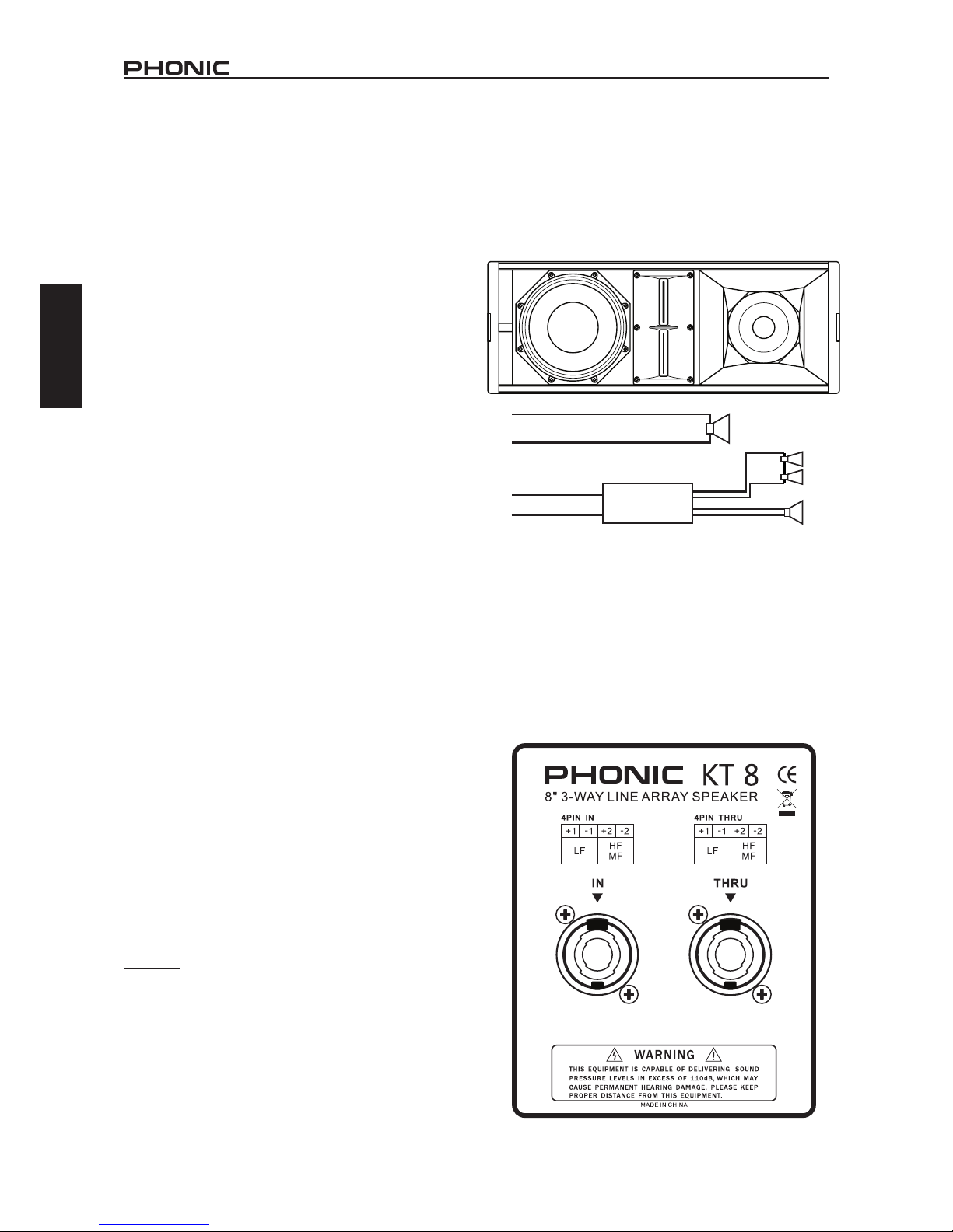
CONECTORES
El KT-8 cuenta con un conector de altavoces de 4
pines NL4. Esto proporciona conectores positivos
y negativos para el Woofer de baja frecuencia, y el
Tweeter de gama media.
El altavoz line-array KT-8 posee ambos conectores
“IN” y “THRU” en el panel posterior. El conector mar-
cado “IN” conecta el amplicador al altavoz, mientras
que el conector “THRU” encadena altavoces adicio-
nales para compartir el poder del amplicador.
1+
+
-
LF
HF
MF
2+
2-
1-
X-OVER
Page 23
2
KT-8A / KT-210A
English Español
CABLEADO
Los cables utilizados para conectar los altavoces
KT-8 deben tener un diámetro adecuado. Ese diámetro se determina según la longitud de los cables
utilizados. La resistencia presentada por el cable
reducirá la potencia de salida de la señal cuando esa
está transferida a través largas distancias. Siendo
este el caso, un cable de menor diámetro se debe
utilizar en distancias más largas.
Para evitar la pérdida de potencia del amplicador,
se recomienda el uso de un cable de altavoz extrafuerte (calibre 12 mínimo). Phonic sugiere un cable
de calibre 10 para distancias más largas. Tenga en
cuenta que muy largas distancias pueden resultar
en pérdida de resistencia.
La imagen de arriba indica la polaridad de cada
conductor que se encuentra en el conector NL4. Por
favor, asegúrese que este cableado es seguido para
garantizar el funcionamiento correcto del altavoz.
Baja
(-)
Baja
(+)
Medias/
Altas
(+)
Medias/
Altas
(-)
1- 1+
2-2+
MONTAJE
La conguración de la matriz se lleva a cabo a través
de un método sencillo de conexión con pines de
bola de pasador. Cada esquina superior de la KT-8
dispone de una articulación retractable. Estas se
extienden para ser insertadas en cada una de las
cuatro ranuras en la parte inferior de la siguiente
unidad. Los pines de bola de pasador encadenados
a la unidad pueden ser insertados en los oricios
adecuados para jar las unidades juntas.
Los pines de bola de pasador tienen un botón en el
extremo que se puede empujar para liberar el pestillo
de la clavija. Esto debe ser empujado al insertar la
clavija en los oricios de montaje.
Los pines de bola de pasador deben estar al ras de la
unidad, y esta debería ser incapaz de mover dentro
del marco de construcción. Para lograr esto, el pin
bola de pasador debe insertarse completamente a
través de los oricios de montaje en ambas unidades
KT-8; a través de los oricios de montaje situados
en la parte inferior de la unidad, a través de la barra
de articulación de la segunda unidad, y en el centro
de la primera unidad.
La esquina inferior, en la parte frontal de cada uni-
dad cuenta con un oricio de montaje. Mientras que
la esquina inferior en la parte trasera de la unidad
ofrece 11 oricios de montaje individuales que van
a determinar el ángulo de dispersión acústica entre
las dos unidades. Si conecta dos unidades a 0 °
creará una dispersión acústica más estrecha, pero
más centrada. A los 10° las unidades crearán una
dispersión vertical mucho más amplia.
10°
9°
8°
7°
6°
5°
4°
3°
2°
1°
0°
Machos/Pines de
enchufe NL4
1 (+/-) 2 (+/-)
Frecuencias Baja
Medias/
Altas
Altavoz
8” 6.5” / 1.4
Manejo de Potencia
RMS
150W 110W
Impedancia Nominal
16Ω 8Ω
BARRA DE ARTICULACIÓN
INSERTOS DE PINES
DE CONEXIÓN
INSERTOS DE PINES
DE CONEXIÓN
Page 24
3
KT-8A / KT-210A
English Español
INSERTOS DE PINES DE CONEXIÓN
MARCO DE MONTAJE
(MODELO # FF640)
INSERTOS DE PINES
DE CONEXIÓN
INSERTOS DE PINES
DE CONEXIÓN
INSERTOS DE PINES DE CONEXIÓN
INSERTOS DE PINES DE CONEXIÓN
INSERTOS DE PINES DE CONEXIÓN
INSERTOS DE PINES DE CONEXIÓN
INSERTOS DE PINES DE CONEXIÓN
INSER
TOS DE PINES DE CONEXIÓN
BARRA DE ARTICULACIÓN
0°
10°
10°
INSERTOS DE PINES DE CONEXIÓN
INSERTOS DE PINES DE CONEXIÓN
INSERTOS DE PINES DE CONEXIÓN
INSERTOS DE PINES DE CONEXIÓN
10°
10°
CONFIGURACIÓN SUGERIDA
Page 25

4
KT-8A / KT-210A
English Español
NO INTENTE LEVANTAR UN LINE-ARRAY/
CONJUNTO DE ALTAVOCES. Bajo ninguna
circunstancia se debe intentar levantar un A rray
por sí mismo. Se recomienda utilizar diversos
dispositivos mecánicos de elevación.
El KT-8 está equipado con un Crossover pasivo
interno para medias/altas. No hay Crossover
presente en el Woofer. Tenga en cuenta que los
altavoces incorrectamente cableados/montados
pueden causar daños a la unidad.
Phonic recomienda tomar el máximo cuidado al
realizar el cableado y / o la conexión de los altavoces.
Un Crossover de 2 vías con un punto de corte en
500Hz es mejor separar las frecuencias bajas de
las frecuencias medias/altas. El rango de frecuencia
ideal para el Woofer de 8” del KT-8 es de 60 Hz a
500 Hz, mientras que la gama media/alta funciona
mejor de 500 Hz a 20 kHz.
Le pedimos que lea todas las instrucciones de
seguridad, las cuales se encuentran junto la página
1 de esta sección del manual.
Los altavoces KT-8 sólo deben ser instalados por
un personal experimentado con el conocimiento
adecuado. Phonic no se responsabiliza de los
altavoces montados incorrectamente que esos sean,
suspendidos o cableados, ni somos responsables
de un equipo que no ha sido inspeccionado antes
de su uso.
Cuando se trabaja con los sistemas line Array KT-8,
la carga total nunca debería superar la capacidad
de resistencia de cada componente individual. Esto
incluye Los pines de bola de pasador, articulaciones
de barras, marco de construcción de suspensión y
de los altavoces.
Mientras que el marco de construcción de suspensión
de los altavoces KT-8 de Phonic tiene una capacidad
de resistencia máxima de 1.000 kg, el examen de
otros elementos de la instalación debe ser tomado
en consideración. Esto puede incluir cables y otros
materiales de suspensión.
Phonic sugiere una margen de seguridad basada
en 1/5 (un quinto) de la capacidad de resistencia
de peso en total. Con esto en la mente, el peso
máximo del conjunto de Altavoces KT-8 / (Array) no
debería alcanzar más de 200 kg utilizando el marco
de construcción de suspensión de Phonic FF640.
Como se indicó anteriormente, sin embargo, el peso
y la resistencia total de otros componentes de la
conguración deben ser tomados en cuenta.
CONSIDERACIONES DE SEGURIDAD
Page 26
5
KT-8A / KT-210A
English Español
KT-8
Woofers 8"
Rango-Medio 6.5"
Tweeter Dos driver de compresión diafragma de titanio de 1.4"
Gama de Frecuencia (-3dB) 70Hz - 19KHz
Cobertura Horizontal 120°
Cobertura Vertical 10°
Manejo de Potencia RMS
LF: 150 Vatios
MF/HF: 110 Vatios
Sensibilidad On-Axis 1W / 1m
LF: 96 dB
MF: 102 dB
HF: 105 dB
Capacidad Maxima de Pico / Rated
Maximum Peak SPL at 1m
LF: 126 dB
MF: 129 dB
HF: 129 dB
Impedancia Nominal
LF: 16Ω
MF/HF: 8Ω
Amplicación de Potencia
Recomendada
LF: 300W
MF/HF: 220W
Material de la Caja
Multicapa de abedul contrachapado de 18mm,
malla de acero negra hexagonal de 8 mm
con espuma acústica especial
Color Negro
Sistema Aparejo Incluido (0° to 10°)
Conectores 2 x Neutrik NL4
Dimensiones (HxWxD) 640 x 380 x 240 mm (25.2" x 15" x 9.4")
Peso 26 Kg (57 lbs)
ESPECIFICACIONES
LINK/
ENLACE
LINK/ENLACE
LINK/
ENLACE
PHONIC i2600 SPEAKER
MANAGEMENT SYSTEM
SUGGESTED CROSSOVER
FREQUENCY: 500Hz (-24dB/Oct)
CROSSOVER de 500Hz (-24 dB/Oct)
iAMP3020
AMPLIFIERS /
AMPLIFICADORAS
MIXER/
MEZCLADORA
HIGH/
MID
LOW/
BAJAS
RL
LINK/
ENLACE
ALTAS/
MEDIAS
Page 27
1
KT-8A / KT-210A
Appendix Apéndice
KT-8A / KT-210A
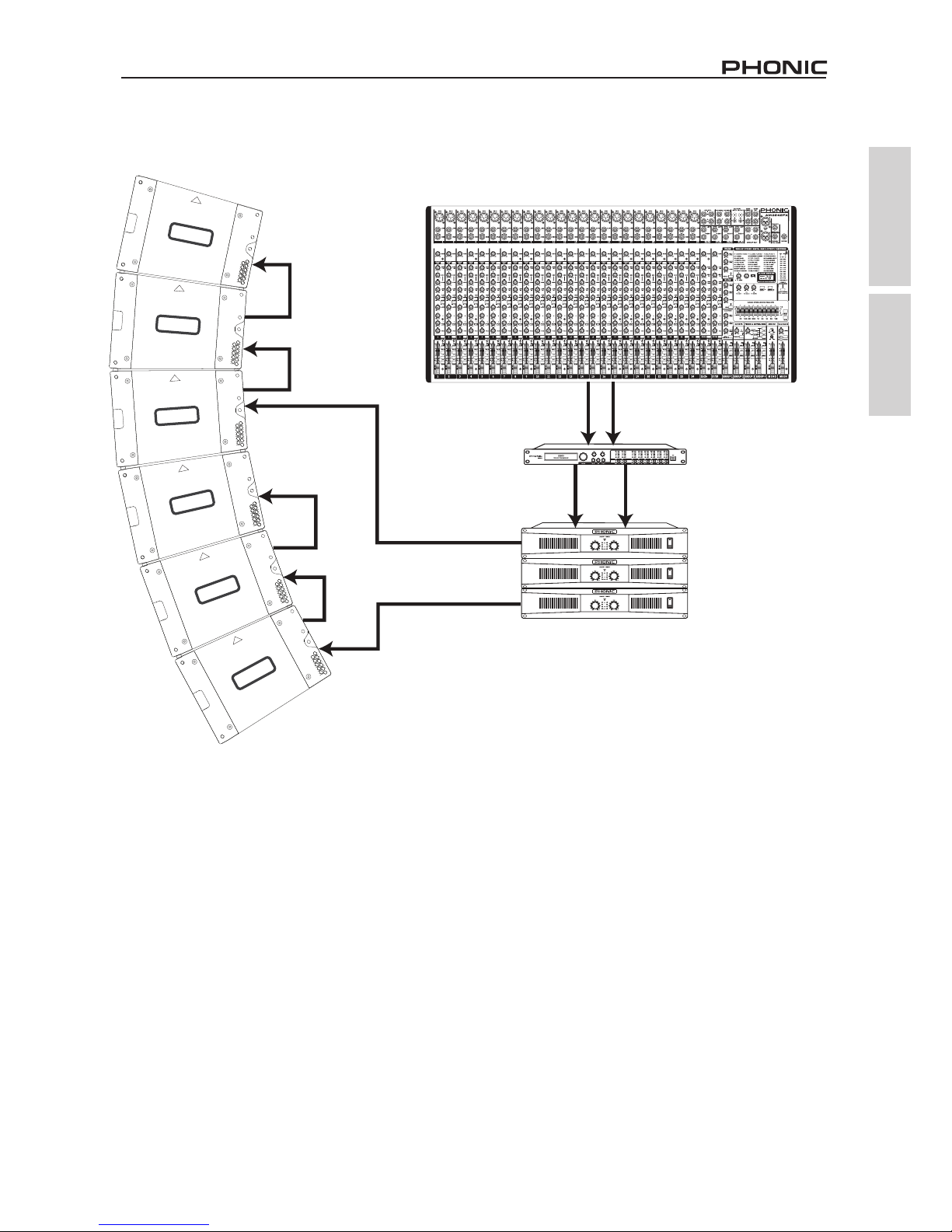
APPLICATIONS APLICACIONES
KT-8
LINK/
ENLACE
LINK/ENLACE
LINK/
ENLACE
PHONIC i2600 SPEAKER
MANAGEMENT SYSTEM
SUGGESTED CROSSOVER
FREQUENCY: 500Hz (-24dB/Oct)
CROSSOVER de 500Hz (-24 dB/Oct)
iAMP3020
AMPLIFIERS /
AMPLIFICADORAS
MIXER/
MEZCLADORA
HIGH/
MID
LOW/
BAJAS
RL
LINK/
ENLACE
ALTAS/
MEDIAS
In the above conguration, the front of house mix is
sent to a 2-way crossover before being sent to power
ampliers. The KT-8 speakers are then powered by
at least two separate power ampliers. A crossover
point of 500 Hz is suggested. For information on wiring the NL4 connectors of the KT-8 please consult
page 2 of this manual.
The array conguration has each speaker at a 10
degree angle. This provides wider vertical coverage,
able to cover longer distances for larger audiences.
Congurations can vary. For more direct, robust
audio, for example, the top two or three speakers
can be mounted at a 0 degree angle, while the lower
speakers can sit at 8 or 10 degrees. See the “Sug-
gested Conguration” section for one such example.
En la conguración anterior, la mezcla frontal se
envía a un cruce/Crossover de 2 vías antes de
ser enviada a los amplicadores de potencia. Los
altavoces KT-8 son entonces alimentados por (al
menos) dos amplicadores de potencia separados.
Para obtener información sobre el cableado de los
conectores NL4 del KT-8 por favor consulte la página
2 de este manual.
Cada altavoz de la conguración Array está colocado en un ángulo de 10 grados. Esto proporciona
una cobertura vertical más amplia, capaz de cubrir
grandes distancias para grandes audiencias. Las
conguraciones pueden variar. Para un audio más
robusto y más directo, por ejemplo, los dos o tres
altavoces de la parte superior del Array se pueden
montar en un ángulo de 0 grados, mientras que los
altavoces inferiores pueden ajustar en 8 o 10 grados.
Vea la sección “Conguraciones sugeridas” para
observar este ejemplo.
Page 28

2
KT-8A / KT-210A
Appendix Apéndice
Measurements are shown in mm/inches
DIMENSIONS DIMENSIONES
Todas las medidas están mostradas en mm/pulgadas
380 / 15
640 / 25.2
240 / 9.4
380 / 15
8°
640 / 25.2
240 / 9.4
Page 29

3
KT-8A / KT-210A
Appendix Apéndice
NOTES
Page 30

 Loading...