

Page 1
KA720
Karaoke Mixing Amplifier
KA720
1
Page 2
1. Re ad the se i ns tr uc ti on s be fo re o pe ra ti ng t hi s
apparatus.
2. Keep these instructions for future reference.
3. Heed all warnings to ensure safe operation.
4. Follow all instructions provided in this document.
5. Do not use this apparatus near water or in locations
where condensation may occur.
6. Clean only with dry cloth. Do not use aerosol or liquid
cleaners. Unplug this apparatus before cleaning.
7. Do not block any of the ventilation openings. Install
in accordance with the manufacturer’s instructions.
8. Do not install near any heat sources such as radiators,
heat registers, stoves, or other apparatus (including
.
9. Do not defeat the safety purpose of the polarized or
grounding-type plug. A polarized plug has two blades
with one wider than the other. A grounding type plug
has two blades and a third grounding prong. The wide
blade or the third prong is provided for your safety. If
the provided plug does not into your outlet, consult
an electrician for replacement of the obsolete outlet.
10. Protect the power cord from being walked on or
pinched particularly at plug, convenience receptacles,
and the point where they exit from the apparatus.
11. Only use attachments/accessories by the
manufacturer.
12. Use only with a cart, stand , tripod, bracket, or
table by the manufacturer, or sold with
the apparatus. When a cart is used, use caution
wh en m ov in g th e cart/apparatus
combination to avoid injury from tipover.
13. Unplug this apparatus during lighting
st or ms or when unused for lon g
periods of time.
14. Refer all servicing to service personnel.
Servicing is required when the apparatus has been
damaged in any way, such as power-supply cord or
plug is damaged, liquid has been spilled or objects
have fallen into the apparatus, the apparatus has
been exposed to rain or moisture, does not operate
normally, or has been dropped.
IMPORTANT SAFETY INSTRUCTIONS
CAUTION: TO REDUCE THE RISK OF ELECTRIC SHOCK,
DO NOT REMOVE COVER (OR BACK)
NO USER SERVICEABLE PARTS INSIDE
REFER SERVICING TO QUALIFIED PERSONNEL
The lightning flash with arrowhead symbol, within an
equilateral triangle, is intended to alert the user to the
presence of uninsulated “dangerous voltage” within the
product
’
magnitude to constitute a risk of electric shock to persons.
The exclamation point within an equilateral triangle is in-
tended to alert the user to the presence of important operat-
ing and maintenance (servicing) instructions in the literature
accompanying the appliance.
WARNING: To reduce the risk of or electric shock, do
not expose this apparatus to rain or moisture.
CAUTION: Use of controls or adjustments or performance
of procedures other than those may result in
hazardous radiation exposure.
The apparatus shall not be exposed to dripping or splashing and that no objects with liquids, such as vases,
shall be placed on the apparatus. The MAINS plug is used as the disconnect device, the disconnect device shall
remain readily operable.
Warning: the user shall not place this apparatus in the area during the operation so that the mains switch
can be easily accessible.
CAUTION
RISK OF ELECTRIC SHOCK
DO NOT OPEN
Page 3

KA720
Karaoke Mixing Amplifier
INTRODUCTION ........................................................................................................4
FEATURES ................................................................................................................ 4
BASIC SETUP
CONTROLS AND CONNECTIONS
APPLICATION ............................................................................................................ 9
SPECIFICATION ...................................................................................................... 10
BLOCK DIAGRAM
........................................................................................................... 4
........................................................................... 5
................................................................................................... 12
Phonic preserves the right to improve or alter any information within this document without prior notice.
V1.0 APR 3th,2008
Page 4
INTRODUCTION
BASIC SETUP
Congratulations for purchasing the Phonic KA720 Karaoke
Mixing Amplifier, another great innovation bound to provide
you with hours of enjoyment at a time. The power provided
to users by the KA720 surpasses that of the average
Karaoke mixer, pumping 360 Watts of power to each
channel.
Featuring a total of 6 microphone inputs, as well as 4 line
inputs, the KA720 features a fully functional key adjustment
and EQs for both vocals and music. Karaoke audio and
video are input via the four included sets of RCA inputs,
and send out via the two sets of RCA outputs.
This user’s manual should be read thoroughly and stored
in an easy to find place for future reference. If you do,
however, lose the manual, you can easily download another
one by logging onto www.phonic.com.
FEATURES
2 x 360W / 4 ohms maximum power output
Switching-mode power supplier for Clear, Powerful
Amplification
24-Bit DSP Reverb and Professional Digital Echo for
Superior Vocal Enhancement
9 Step Digital Key Controller Changes the Key of the
Music without Changing the Tempo
On Board Video Switching with 4 Sets of A/V Inputs, 2
Audio Outputs and 2 Video Output
6 Microphone Inputs
One AUX output and one Stereo AUX input
Individual Microphone Bass & Treble Controls
Music Bass & Treble Controls
Music Balance Control
Master Microphone and Music Volume Controls
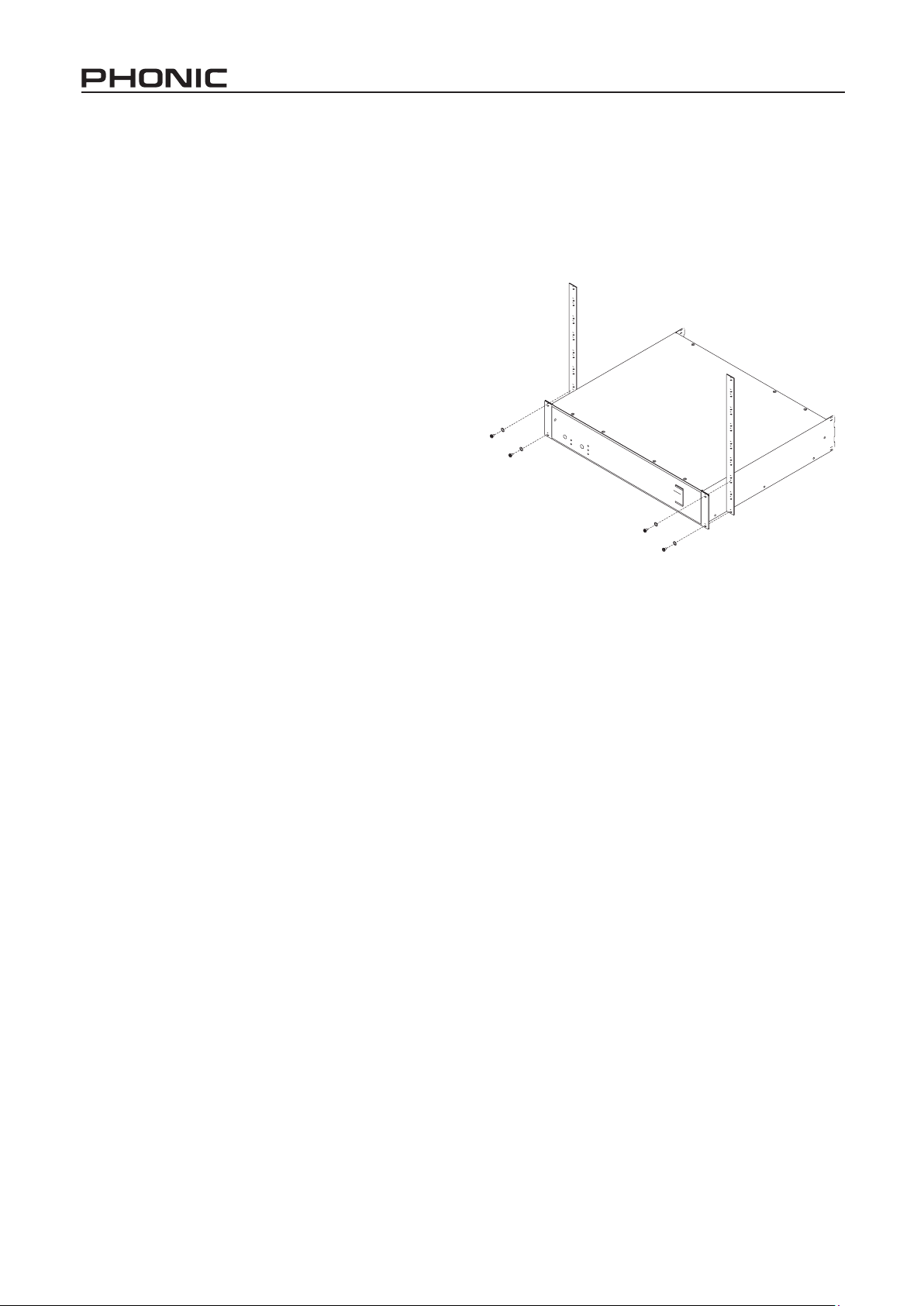
The KA720 Karaoke Mixing Amplifier can be rack mounted,
and will take up 3 standard rack units to do so. Your first
step, provided you wish to mount the KA720 into a rack,
should be to do so. Four screws, firmly in place on each
corner of the unit, will do the trick.
After this, you may wish to connect your various input, and
output, devices. The four different RCA input channels
provide you with enough to room for a DVD player with
karaoke function (or simply a DVD player, for use between
karaoke sets), an actual karaoke machine, a PC computer
(for users who opted to have the VGA inputs and outputs),
or even a standard CD player (which will not feature video
output, but can be used regardless). The Microphone inputs
on the front of the KA720 are provided for the addition of,
you guessed it, microphones. If condenser microphones
are added to the KA720, be sure to activate the Phantom
power.
Plugging the RCA audio and video outputs of the KA720
allows the audio and video to be sent to a television set
or video projection device. Passive speakers can be
connected to the main audio outputs and positioned for the
best listening experience.
Use the provided AC power cord to connect the KA720 to
an appropriate power source. Be sure to check the voltage
selector is adjusted correctly before turning the unit on.
4
KA720
Page 5

CONTROLS AND CONNECTIONS
1 2 3
5 6 7
4
Front Panel
1. Power Button
This button activates the KA720 Karaoke Mixer. When
pushed in, the LED will light up and your unit will be
functional.
Channel Strips
2. Line Input
This is a 1/4” TRS input, which accepts line-level devices
for signals to be fed through to the KA720 Karaoke Mixing
Console. This can be used for microphones that use 1/4”
jacks, however can also extend to certain instruments or
audio equipment.
3. Mic Input
This female XLR jack allows you to plug microphones into
the mixer. Singers are then able to do their thing, the result
of which will be sent to the main mix at a level determined
by the channel’s gain and level controls.
4. Gain Control
The gain control allows users to increase and decrease the
level of the signal received through the Mic and line inputs.
This can help boost the signal prior to it being adjusted by
the channel controls.
5. 2-band EQ (Low and High Controls)
These controls give a shelving boost or cut of 15 dB to high
frequency (12 kHz) and low frequency (80 Hz) sounds.
Depending on the strengths of the vocalist, it may be
desirable to cut middle frequency sounds a little bit, while
boost high and low frequencies slightly.
6. Delay+Rev Control
This control adjusts the level of audio that is sent from the
channel to the Echo Mixing Bus.
7. Level Control and Peak Indicator
This fader quite simply allows users to adjust the final
output level of that particular channel, the signal of which is
sent to the main mixing bus. The peak indicator will light up
when the output signal of the channel reaches high peaks
and should be lowered. For best results, the level control
can be adjusted to a level that allows the peak indicator to
ash infrequently.
KA720
5
Page 6

Main Section
8
9
10
11
12
13
20
17 19
14
18
1615
13. Mic Master Volume Control
This control adjusts the volume of all microphone input
channels combined, allowing users to easily adjust vocals
to suit the music.
14. 2-band Music EQ (Low & High Controls)
Just like the EQ on each channel, the system EQ gives a
shelving boost or cut of 15 dB to high frequency (12 kHz)
and low frequency (80 Hz) sounds. Only the music inputs
are affected by the system equalizer.
15. EFX In Control
This control adjusts the level of any signal fed through the
EFX input, sent to the main audio mix.
8. Mic 5 & 6
These individual Microphone inputs are similar to input
channels 1 through to 4, however do not feature 1/4” phone
jacks, EQs or level controls. These channels do feature
‘delay+rev’ and gain controls, however, allowing users to
adjust the audio level sent to the echo and main mixes,
respectively.
Built-in Echo
9. Echo Control
This control adjusts the level of saturation added to the signal
sent to the “echo” mix (the final level of which is adjusted by
the ‘delay+rev’ controls on individual channels).
10. Repeat Control
This control allows users to adjust level of the repeat effect,
built into the KA720, the final level of which is adjusted by
the ‘delay+rev’ controls on individual channels. Basically,
it determines the degree of attenuation between each
repeat.
11. Delay Control
This control allows users to adjust the delay time of the
signal sent to the Echo Mix. Working in conjunction with the
Repeat Control, users are able to apply a very interesting
echoing effect to vocals, if they wish.
12. Reverb Control
This control allows users to add a reverb effect to their
audio, basically controlling the level of the audio sent from
the Echo mix to the main mix.
16. Music Balance Control
This alternates the degree or level of the music signal that
the left and right side of the main mix should receive. By
adjusting the balance control, users affectively attenuate
the left or right audio signals according to the degree of
their rotations.
17. Input Selection
These buttons allow users to select from the various inputs
with the touch of a button. This ensures users to can simply
switch from a single input source to another, without the
hassle of rewiring
18. Master Volume Control
This control adjusts the volume of the music, allowing
users to attenuate or intensify the level accordingly.
6
KA720
Page 7

19. Level Meter
27
The KA720’s level meter gives an accurate indication
of when audio levels of the main signal reach certain
levels. To make the maximum use of audio, set the
various levels controls so that the uppermost LED of
the level meter ashes only occasionally, or not at
all.
20. Key Control and Indicators
This area allows users to control the key of the music
currently selected (through use of the input select
buttons), and does not affect the vocal channels
whatsoever. The key can be increased or decreased
in half-key increments by pressing the appropriate
buttons (the top button being increase, the lower
button being decrease). The center key is used to
return the music back to its original state.
When a key is increase by half a step, two of the
included LEDs will illuminate to indicate the key is half
way between the two. When the key is increased by
another half step, only the single LED will illuminate
(and so on). The maximum a user can increase or
decrease the key by is 4 steps.
23
26
25
24
23. EFX Input
These 1/4” phone jacks are for returning the EFX signal
to the KA720, after being processed by an external signal
processor. The EFX Input signal is adjusted by the EFX In
control located on the front panel of the KA720.
24. EFX Output
This jack outputs the main signal to external processors to
be returned via the EFX input.
Rear Panel
21. Video and Audio Inputs
These RCA jacks allow users to connect video and audio
inputs to the KA720. The RCA jacks are color-coded,
yellow being video, white being the left audio channel and
red being the right audio channel. Users are able to select
from these inputs by using the Input Selection buttons on
the front panel.
22. Video and Audio Outputs
These two sets of RCA jacks are for the output of video and
audio from the KA720 to televisions or video projectors and/
or stereo systems. The Preamp output (the output of which
is not affected by the balance control on the front panel)
can be used for displaying the video and audio signals to a
small television set for monitoring purposes.
21 22
25. EQ In and Out
These stereo RCA inputs and outputs allow users to extract
the main audio signal from the KA720, send it off to an
external equalizer, and then return it to the device once
more.
26. Remote Key Control
These 1/8” TRS inputs are for customized key control
pedals. Users should wire their pedal so that when the
connector’s tip and sleeve form a connection, the key will go
up by half a step and that when the ring and sleeve touch,
the key will go down by half a step. A total of two remote
key controls can be used simultaneously, both of which will
affect the main Key Control unit on the front panel.
27. Fan
This fan is for cooling of the KA720 karaoke mixer, and
should not be obstructed at any time. Doing so may cause
overheating in the product.
KA720
7
Page 8

28. Main Output Jacks
28
These binding-post terminals are for the addition of passive
speakers to the KA720. Users can connect standard
banana plugs to these terminals to get the final amplified
signal of the KA720. In addition to using banana plugs with
the included binding posts, users may also opt to use freewires to connect to the KA720. To do so, simply unscrew
the binding post, slide the wire into the small hole in the
binding post, and screw the binding post back in. Ensure
no wire is exposed after the connection is made.
29. Voltage Selector
This switch allows users to adjust the KA720 to areas with
varying voltage levels. For example, in the United States,
the switch would be set to 115V, whereas in, say, England,
it would be set to 230V. Users should check local voltage
levels before operating this unit.
29
30. Power Connector
This is for the addition of an AC power source to the KA720
unit.
30
Connecting speakers
Binding Posts
8
KA720
Page 9

APPLICATION
KA720
9
Page 10

SPECIFICATION
Power Amp 2 x 360W into 4 ohms
Inputs
Mic 6 x XLR
Line 4 x 1/4”
EFX In Stereo 1/4”
EQ in 1 stereo RCA
RCA Audio Source 6 stereo
RCA Video Source 4
Output
Preamp out 1 stereo RCA + 1 video RCA
Monitor out 1 stereo RCA + 1 video RCA
EQ out 1 stereo RCA
Echo Send 1 Phone Jack
Speaker Two pair Stereo Binding Post
Channels
Fader 60 mm (-∞ to +10dBu)
EQ 2-band
Echo Send per Channel
LED Indicators
Input Channel Peak Light Red (x4)
Source Input Green (x4)
Key Change Red (x8) - pitch shift; Green (x1) - neutral
Level Meter 2 x 10
EQ 2-band system
High 12 kHz +/-15dB
Low 80 Hz +/-15dB
Key Control
Touch Control (face panel) Up# & Downb in Half-key step
Wired Control (back panel) Two Mini-TRS phone-jack for Individual control
Echo on Board
Repeat (FB%) 0 - 96 %
Delay (ms) 0 - 800 ms
Reverb (sec) 0 - 2 sec
System
Main Mic Volume +10 dBu (max)
Main Music Volume +18 dBu (max)
Frequency Response 20 Hz ~ 20 kHz ±2dB
Hum (all CH@0dB unity gain) >-74 dBu
THD 0.02%
AC Mains 110-120V, 220-240V/50-60Hz
Crosstalk >-80 dB
Dimensions (W x H x D) 482 x 133 x 415 mm (19” x 5.24” x 16.3”)
Weight 10.3 kg (22.6 lb)
10
KA720
Page 11

BLOCK DIAGRAM
LE
N
NA
HC
O
NO
M
B
D
0
1
+
B
D
0
1
+
KA
E
P
B
D
0
1
+
B
D
0
1
+
BD01
+
R
P
M
A
L
P
M
A
BD0
1+
PM
A
PM
A
ECHO
MIC L
LN
I
SUM
RN
I
SUM
MAIN L
MAIN R
MIC R
N
I
CI
M
HCTIP
/
PS
D
N
I
R
XUA
4
~1H
C
N
I
EN
IL
R
E
D
A
F
HC
OH
C
E
N
I
L
D
L
C
D
L
C
REDAF
HC
T
UO/NI
Q
E
)
T
U
O
X
F
E
(
O
HC
E
wo
L
4
~1HC
N
I
RL
X
R
E
TEM
+
-
N
I
L
XU
A
TUPN
I
C
I
S
UM
L
P
M
A
E
R
P
T
APER
Y
ALED
DVD
LN
I
X
U
A
1
2
3
b
O
E
D
IV
PM
AERP
LO
V
C
I
S
UM
L
O
V
C
I
M
#
w
o
L
+
-
RN
I
X
U
A
1
2
3
OHCE
R R
O
TIN
OM
N
I
O
E
DI
V
D
L
C
L R
O
TIN
O
M
NI
OEDI
V
D
VD
NI
O
EDI
V
XU
A
N
I
R
D
V
D
M
GB
N
I
L MGB
h
giH
N
I
R
D
L
C
O
E
D
I
V ROTINOM
hg
i
H
X
U
A
D
V
D
N
I
L
D
V
D
3
2
1
6
/
5
H
C
N
I
RLX
OH
C
E
N
IA
G
N
IA
G
DLC
QE
M
G
B
QE
HC
BREV
ER
X
U
A
R
PM
A
E
R
P
NI
O
EDI
V M
G
B
OEDI
V
NI X
U
A
E
C
N
AL
A
B
N
I
R
M
GB
KA720
11
Page 12

TO PURCHASE ADDITIONAL PHONIC GEAR AND ACCESSORIES
To purchase Phonic gear and optional accessories, contact any authorized Phonic
distributor. For a list of Phonic distributors please visit our website at www.phonic.com and
click on Get Gear. You may also contact Phonic directly and we will assist you in locating
a distributor near you.
SERVICE AND REPAIR
For replacement parts, service and repairs please contact the Phonic distributor in your
country. Phonic does not release service manuals to consumers, and advice users to not
attempt any self repairs, as doing so voids all warranties. You can locate a dealer near you
at http://www.phonic.com/where/.
WARRANTY INFORMATION
Phonic stands behind every product we make with a no-hassles warranty. Warranty
coverage may be extended, depending on your region. Phonic Corporation warrants this
product for a minimum of one year from the original date of purchase against defects in
material and workmanship under use as instructed by the user’s manual. Phonic, at its
option, shall repair or replace the defective unit covered by this warranty. Please retain the
dated sales receipt as evidence of the date of purchase. You will need it for any warranty
service. No returns or repairs will be accepted without a proper RMA number (return
merchandise authorization). In order to keep this warranty in effect, the product must have
been handled and used as prescribed in the instructions accompanying this warranty. Any
tempering of the product or attempts of self repair voids all warranty. This warranty does
not cover any damage due to accident, misuse, abuse, or negligence. This warranty is
valid only if the product was purchased new from an authorized Phonic dealer/distributor.
For complete warranty policy information, please visit http://www.phonic.com/warranty/.
CUSTOMER SERVICE AND TECHNICAL SUPPORT
We encourage you to visit our online help at http://www.phonic.com/support/. There you
can find answers to frequently asked questions, tech tips, driver downloads, returns
instruction and other helpful information. We make every effort to answer your questions
within one business day.
support@phonic.com http://www.phonic.com
Page 13

 Loading...