

Instruction Manual
Specification:
Wingspan: 133 cm (52.3 inches)
Length : 104 cm (40.9 inches)
Weight : 1830gr
Engine : 25 - 32 two stroke
Radio : 4 channel - 4 servo
HIGH WING

1
AIR FRAME ASSEMBLIES
(2) Wing halves with ailerons
(1) Fuselage with motor mount
(1) Horizontal stabilizer
with elevator halves
(1) Vertical stabilizer with rudder
MAIN GEAR ASSEMBLY
(2) Main gear
(2) 50mm diameter wheels
(4) Wheel collars
(4) 3mm x 6mm set screws
(2) Nylon strap
(4)
3mm x 12mm sheet metal screw
NOSE GEAR
(1) Nose gear
(1) Steering arm
(1) 50mm diameter wheel
(2) Wheel collars
(2) 3mm x 6mm set screws
(1) Metal connector
(1) 4mm x 4mm machine screw
(1) 1,3mm x 500mm wire
(1) 3,5mm x 350mm nylon pushrod
ELEVATOR CONTROL SYSTEM
(1) Nylon clevis
(1) Silicone tube
(1) Nylon snap keeper
(1) Nylon control horn w/plate
(2)
2mm x 12mm sheet metal screw
RUDDER CONTROL SYSTEM
(1) Nylon clevis
(1) Silicone tube
(1) Nylon snap keeper
(1) Nylon control horn w/plate
(2) 2mm x 12mm sheet metal screw
AILERON CONTROL SYSTEM
(2) 2mm x 180mm threaded wires
(2) Nylon clevis
(2) Silicone tube
(2) Nylon snap keeper
(2) Nylon thread connector
(1) Plywood
(2) 8mm x 9mm x 45mm light wood
KIT CONTENTS: We have organized the parts as they come out of the box for better
identification during assembly. We recommend that you regroup the parts in the same
manner. This will ensure you have all of parts required before you begin assembly.
KIT CONTENTS
SUGGESTION:
To avoid scratching your new
airplane, do not unwrap the pieces
until they are needed for assembly.
Cover your workbench with an old
towel or brown paper, both to
protect the aircraft and to protect
the table. Keep a couple of jars or
bowls handy to hold the small parts
after you open the bag.
NOTE:
Please trial fit all the parts. Make
sure you have the correct parts and
that they fit and are aligned
properly before gluing! This will
assure proper assembly. The
SONIC ARF is hand made from
natural materials, every plane is
unique and minor adjustments may
have to be made. However, you
should find the fit superior and
assembly simple.
The painted and plastic parts used
in this kit are fuel proof. However,
they are not tolerant of many harsh
chemicals including the following:
paint thinner, C/A glue accelerator,
C/A glue debonder and acetone. Do
not let these chemicals come in
contact with the colors on the
covering and the plastic parts.
SAFETY PRECAUTION:
• This is not a toy
• Be sure that no other flyers are
using your radio frequency.
• Do not smoke near fuel
• Store fuel in a cool, dry place,
away from children and pets.
• Wear safety glasses.
• The glow plug clip must be
securely attached to the glow
plug.
• Do not flip the propeller with your
fingers.
• Keep loose clothing and wires
away from the propeller.
• Do not start the engine if people
are near. Do not stand in line with
the side of the propeller.
• Make engine adjustments from
behind the propeller only. Do not
reach around the spinning
propeller.
MOTOR MOUNT ASSEMBLY
(4) 3mm x 25mm machine screws
(4) 4mm x 25mm wood screws
THROTTLE CONTROL SYSTEM
(1) 1,3mm x 500mm wire
(1) 3,5mm x 350mm nylon
pushrod housing
(1) Metal connector
(1) 4mm x 4mm machine screw
FUEL TANK
(1) Nylon fuel tank
(1) Metal clunk
(1) Silicone tube / 80mm
(1) Pre - assembled stopper w / 2 tube
(1) 165mm x 250mm foam rubber
MISCELLANEOUS ITEMS
(1) Plywood dihedral brace
(2) 15mm x 15mm x 8mm blok of wood
(2) 15mm wood triangle stock
(1) 25mm x 600mm trim tape
(2) 115mm wood dowels
(12) Ruber bands
(1) Set of two pushrods
(2) Plywood
ADDITIONAL ITEMS REQUIRED
• 25 - 32 two stroke engine
• 4 channel radio with 4 servo
• Glow plug to suit engine
• Propeller to suit engine
• Protective foam rubber
• Silicone fuel line
• Stick on weight for balance
• Spinner: 2" (52mm)
TOOLS AND SUPPLIES NEEDED
• Medium thick C/A glue.
• 30 minute epoxy
• 6 minute epoxy
• Hand or electric drill
• Assorted drill bits
• Modeling knife
• Straight edge ruler
• Pliers large and small
• Wire cutters
• Masking tape
• Thread lock
• Paper towels
• Rubbing alcohol
2
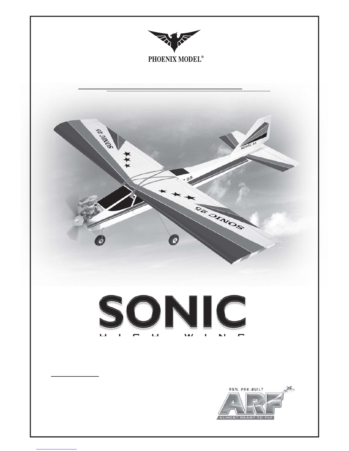
• Draw a center line on the wing joiner.
• Glue wing joiner in wing halves with 30 minute
epoxy. Put epoxy on wing joiner and in wing
joiner pocket. Wipe off excess epoxy with a
paper towel and alcohol.
• Hold wing halves together with tape while
epoxy cures.
• Cover wing joint with self adhesive trim strip.
• Glue 2 pieces of plywood onto the wing
with CA glue.
Center line
Tape
Joiner
4
Tape
WING ASSEMBLY
5
Ply wood

3
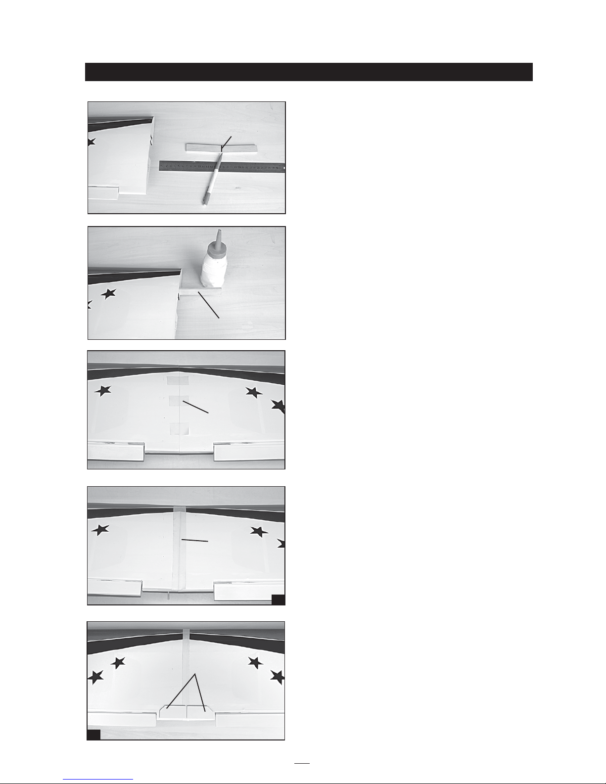
• Locate aileron servo mouting tray. Trim covering
from bottom of wing for aileron servo and tray. 6
minute epoxy the tray in place centered over the
aileron servo opening using the supplied spacer
blocks (trim to fit as needed).
• Install aileron servo using hardware supplied
with radio gear.
• Install the threaded connectors onto the aileron
torque rods.
• Thread one nylon clevis at least 6mm onto one of
the 2mm x 180mm threaded wires. Install a
silicone tube on the clevis. Attach the clevis to the
hole in the threaded connector. Locate one nylon
servo arm and using a wire cutter remove all but
two of the arms. Using a 2mm drill bit, enlarge the
third hole out from the cnter to accommodate the
aileron pushrod wire. Plug the aileron servo into
receiver and ceter the servo. Install the servo arm
onto the servo. The servo arm should be
perpendicular to the servo. Center the aileron and
hold it place using a masking tape.
With the aileron and aileron servo centered, carefully place a mark on the aileron pushrod wire where it crosses the
hole in the servo arm. Using pliers, carefully make a 90 degree bend down at the mark made. Cut off the excess wire,
leaving about 4mm beyond the bend. Insert the 90 degree bend down through the hole in the servo arm. Install one
nylon snap keeper over the wire to secure it to the arm. Install the servo arm retaining and remove the masking tape
from the aileron. Repeat for the second aileron linkage.
Thread connector
20mm
Silicone tube
Snap
keeper
Clevis
Servo tray
Tape
Snap keeper
Clevis
Thread connector
Aileron pushrod

4
• Center the wing. Cut the covering from the slots
in the fuselage for the horizontal stab and vertical
fin. Put horizontal stab on fuselage and center like
the wing, also level the stab to match up with the
wing. Mark the horizontal stab where it will glue
to the fuselage.
• Glue stab on with 30 minute epoxy and recheck
alignment.
• Trim the covering from the stab where it will glue
onto the fuselage. Cut only through the covering,
do not cut into the balsa.
• Cut the covering from the holes for the wing
dowels in the fuselage. Glue the dowels in place
with C.A
• Rubber band wing onto fuselage with suppied
rubber bands. See photo.
horizontal - vertical installation
BB
BB
AA
AA
Remove the covering
Dowel

5
• Put vertical fin in fuselage slot, mark where
covering needs to be trimmed. Carefully trim
covering. Line up vertical fin and epoxy in place
keeping the vertical fin perpendicular to the stab.
• Cut the covering the slot in the landing gear mount.
• Put landing gear wires in fuselage bottom and secure
using screws and nylon straps.
main gear installation
Nylon step
Landing gear
Screw
• Fit the nose leg steering arm onto the "Z" bend on
the steering pushrod. Now slide the steering arm
into the middle of the pre-fitted nylon nose gear
bearing. Hold the nose gear steering arm in place
then slide the nose wire into the nylon mount,
passing through the steering arm. Note that the
ground flat section of the leg should face forward.
Now tighten the nose gear steering arm retaining
screw onto the nose leg. This will ensure that the
nose leg cannot turn in the steering arm.
• Put wheels on the gear and secure using the
wheel collars.
Nose gear
Steering arm
Wire
pushrod
Remove the
covering
Glue epoxy
Collar

6
• Assemble the fuel tank.
Collar
• Install nose wheel using supplied wheel collars.
• Put the fuel tank in the fuselage using foam rubber
to cushion the tank, and route the fuel lines out
the hole in the firewall.
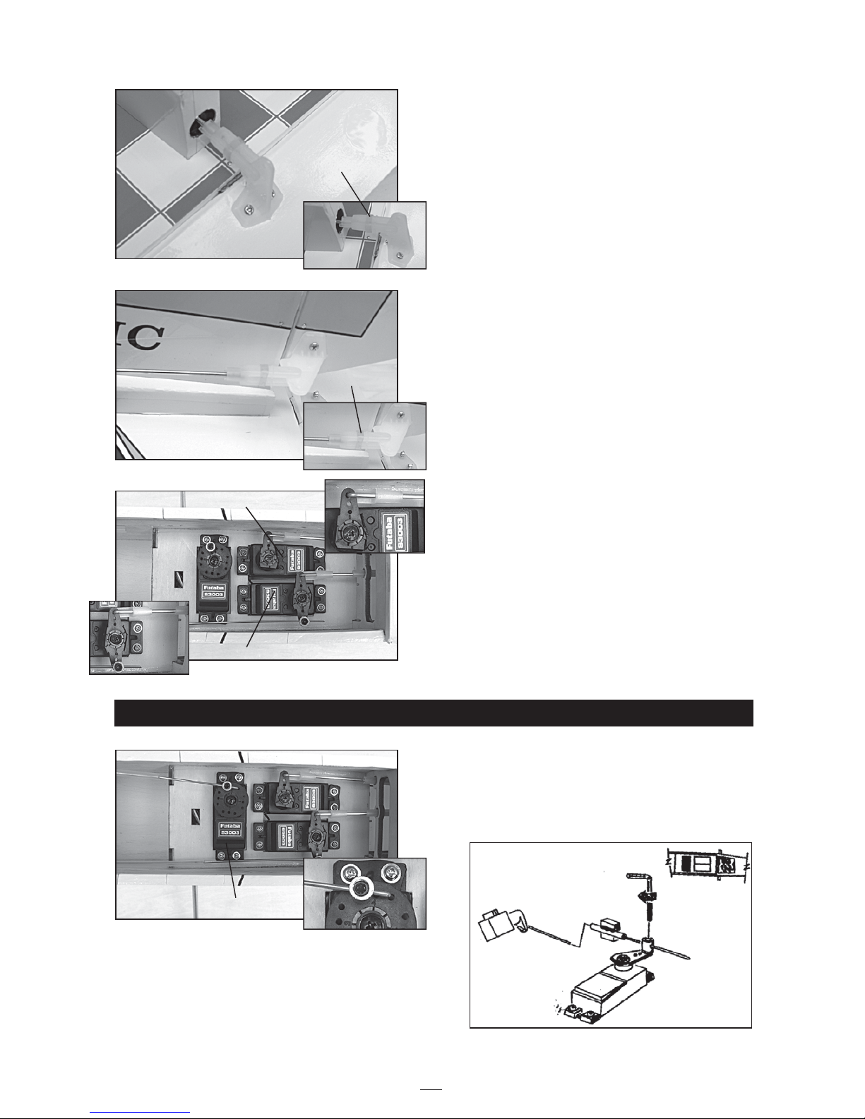
. Insert the Z - bend of the throttle pushrod into the
throttle arm of the engine. See the "high throttle"
photo on page 9.
. Istall the engine of your choice using the Philip
head screws. Make sure the engine is pointing
straight ahead or pointing a little to the right, i. e.
with right thrust. Mark the locations of the screws
and drill mounting holes with a drill bit that is
slightly smaller than the screw threads. Test to get
the right size drill bit before drilling holes in the
engine mount.
fuel tank installation
engine installation
To muffler
To carburator
Down thrust 2
0
To muffler
To carburator
80mm
2.5mm
Right thrust 2
0

7
• Install the rubber grommets and brass eyelets into
the elevator, rudder and throttle servos. Test fit
the servos into the servo tray.
• Mount the servos to the tray using the mounting
screws provided with your radio system.
servo installation
elevator - rudder linkage
Throttle servo
Rudder servo
Elevator servo
• Remove the covering from the hole as shown.
• The elevator control horn should be mounted on
the bottom of the elevator at the leading edge,
IN LINE WITH THE ELEVATOR PUSHROD.
• Cut the covering from the exit slot for the rudder
pushrod on the top of the fuselage, on the left side
of the vertical fin.
• The rudder control horn should be mounted on
the left of the rudder at the leading edge,
IN LINE WITH THE RUDDER PUSHROD.
Hole
Screw
Control horn
Screw
Control horn
8
throttle linkage
• Install the elevator pushrod in fuselage. Thread a
nylon clevis at least 6mm onto the pushrod. Route
it to the elevator, attach clevis to horn and secure
using small piece of silicone tubing.
Silicone tube
• Install the rudder pushrod in fuselage. Thread a
nylon clevis at least 6 mm onto the pushrod. Route
it to rudder, attach clevis to horn and secure using
small piece of silicone tubing.
• Trim and attach the pushrod to the servos using
fast loc connectors.
• Install a metal connector onto the rudder servo
arm and connect the nose wheel steering
pushrod to it.
• Attach throttle pushrod to throttle servo arm using
a metal connector. Use two wood blocks to hold
the pushrod securely.
Silicone tube
Throttle servo
Rudder servo
Elevator servo
9
This is a very important stage in the completion of
the model. The throttle must open and close fully without the linkage binding at either end of its travel.
Work by setting the "mid throttle" position first,
followed by the low and high. Once the linkage
has been properly set-up it can be adjusted
mechanically or by using the Travel Adjust, or
ATV/EPA feature on most modern transmitters.
Note: The final adjustment of the low throttle point
can only be carried out with the engine running.
setting up the throttle
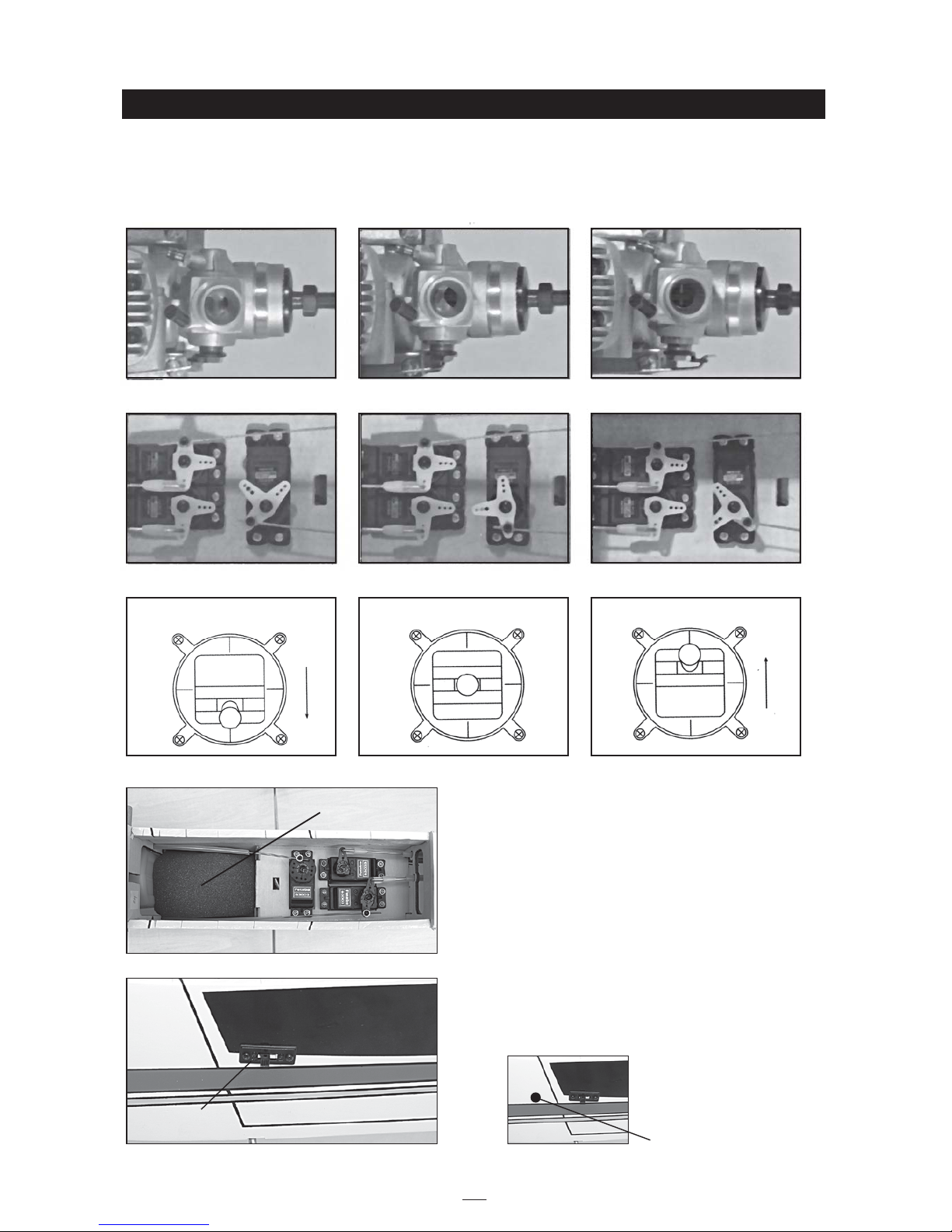
• Wrap battery and receiver in protective
foam padding.
• Install the switch.
Low throttle Mid throttle High throttle
Low throttle stick position Mid throttle stick position High throttle stick position
Antenna exit
Switch
Receiver - battery

10
BALANCING
1. It is critical that your airplane be balanced correctly.
Improper balance will cause your plane to lose
control and crash.
Place receiver and battery in radio compartment and
adjust their position to make the plane blance on the
center of gravity (70mm from leading edge of wing).
Make sure the center of gravity is located where it is
indicated before flying. If additional tail or nose
weigh is needed, securely attach it at the nose or tail
as needed.
2. Wrap battery and receiver in protective foam
padding. Route the receiver antenna out of the
fuselage and to the rear of the airplane. Secure to
the vertical fin or one side of the horizontal stab with
a pin and small rubber band.
CONTROL THROWS
1.
We highly recommed setting up a plane using the
control throws listed. Adjust pushrod positions on
control arms or horns to provide control surface
throws as illustrated. Center all control surfaces.
2. The control throws should be measured at the
widest point of each surface!
FLIGHT PREPARATION
PRE FLIGHT CHECK
1. Completely charge your transmitter and receiver
batteries before your first day of flying.
2. Check every bolt and every glue joint in your
plane to ensure that everything is tight and well
bonded.
3. Double check the balance of the airplane
4. Check the control surface
5. Check the receiver antenna . It should be fully
extended and not coiled up inside the fuselage.
6. Properly balance the propeller.
7. Use at leat 5 rubber bands per side to hold the
wing onto the fuselage.
We wish you many enjoyable flights with
your plane and once again thank you for
your choosing a Phoenix Model's product.
Ailerons : 5mm up 5mm down
Elevator : 8mm up 8mm down
Rudder : 13mm right 13mm left
65 - 70mm
Elevator Control
Aileron Control
5mm
5mm
Rudder Control
13mm
13mm
8mm
8mm
Metric Conversions
Inches x 25.4 = mm (conversion factor)
1/64" = .4 mm 3/16" = 4.8 mm 1" = 25.4 mm 21" = 533.4 mm
1/32" = .8 mm 1/4" = 6.4 mm 2" = 50.8 mm 24" = 609.6 mm
1/16" = 1.6 mm 3/8" = 9.5 mm 3" = 76.2 mm 30" = 762.0
mm
3/32" = 2.4 mm 1/2" = 12.7 mm 6" = 152.4 mm 36" = 914.4 mm
1/8" = 3.2 mm 5/8" = 15.9 mm 12" = 304.8 mm
5/32" = 4.0 mm 3/4" = 19.0 mm 18" = 457.2 mm
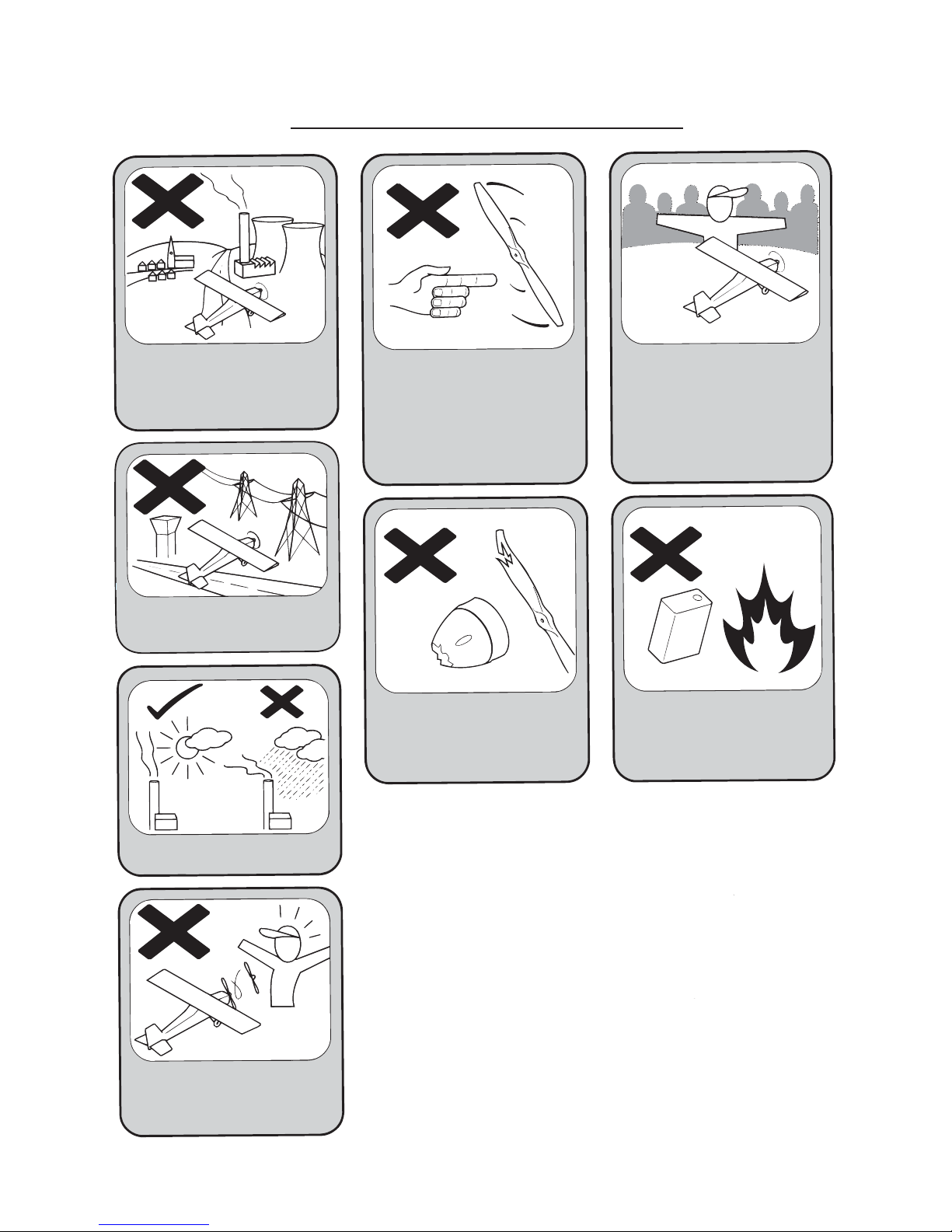
I/C FLIGHT WARNINGS
Always operate in open areas, away
from factories, hospitals, schools,
buildings and houses etc. NEVER fly
your aircraft close to people or built
up areas.
THE PROPELLER IS DANGEROUS
Keep fingers, clothing (ties, shirt
sleeves, scarves) or any other loose
objects that could be caught or drawn
in, away from the propeller. Take care
at ALL times.
Keep all onlookers (especially small
children and animals) well back from
the area of operation. This is a flying
aircraft, which will cause serious
injury in case of impact with a person
or animal.
NEVER fly near power lines, aerials
or other dangerous areas including
airports, motorways etc.
NEVER use damaged or deformed
propellers or spinners.
DO NOT dispose of empty fuel
containers on a fire, this can lead to
an explosion.
NEVER fly in wet conditions or on
windy or stormy days.
ALWAYS adjust the engine from
behind the propeller, and do not allow
any part of your body to be in line
with the propeller.
Made in Vietnam
 Loading...