

Page 1

OVENS and INCUBATORS
User Manual
Page 2

Index
1 Warranty ............................................................................................................................................................ 1
2 Contents of package .......................................................................................................................................... 1
3 First use ............................................................................................................................................................. 1
3.1 Getting started ........................................................................................................................................... 1
3.2 Instrument parts ........................................................................................................................................ 1
4 Display and commands ..................................................................................................................................... 2
5 Instrument versions ........................................................................................................................................... 3
6 Operation (Basic version) .................................................................................................................................. 4
6.1 Switching on the instrument ...................................................................................................................... 4
6.2 Setting of parameters ................................................................................................................................ 4
6.2.1 Working temperature ........................................................................................................................ 4
6.2.2 Working time ..................................................................................................................................... 4
6.2.3 Fan speed (forced air instruments only) ........................................................................................... 4
6.3 Start/stop heating cycle ............................................................................................................................. 5
6.4 Functions with password access ............................................................................................................... 5
6.4.1 Access to menu with password ......................................................................................................... 5
6.4.2 Delay of heating cycle start ............................................................................................................... 5
6.4.3 Safety temperature limiter for samples protection ............................................................................ 6
6.4.4 Restart mode after absence of power supply ................................................................................... 6
6.4.5 Temperature range for over temperature alarm ................................................................................ 7
6.4.6 Temperature offset on single point, on entire ramp, on room temperature sensor ........................... 7
7 Operation (Professional version) ....................................................................................................................... 9
7.1 Switching on the instrument ...................................................................................................................... 9
7.2 Programming ............................................................................................................................................. 9
7.2.1 Calling programs ............................................................................................................................... 9
7.2.2 Modify a program .............................................................................................................................. 9
7.3 Start/stop of a program ............................................................................................................................ 10
7.4 Functions with password access ............................................................................................................. 10
7.4.1 Access to menu with password ....................................................................................................... 10
7.4.2 Number of program to which apply the Delay and Cycle functions ................................................ 11
7.4.3 Ripetition of a program .................................................................................................................... 11
7.4.4 Delay of the program start .............................................................................................................. 11
7.4.5 Safety temperature limiter for samples protection .......................................................................... 12
7.4.6 Restart mode after absence of power supply ................................................................................. 12
7.4.7 Temperature range for over temperature alarm .............................................................................. 13
7.4.8 Temperature offset on single point, on entire ramp, on room temperature sensor ......................... 13
8 Clean and maintenance ................................................................................................................................... 14
9 Disposal of electronic equipment ..................................................................................................................... 14
9.1 Technical specifications and service ................................................................................................................ 14
Page 3

Ver. 1.1 – 14/05/2015
1
1 Warranty
Thank you for purchasing a product from Phoenix Instrument GmbH. In normal use conditions, the
instrument is guaranteed for a period of 24 months from the date of purchase.
The warranty is valid only if the product is original. It does not apply to any product or parts of it
that have been damaged due to incorrect installation, improper connections, improper use,
accident or abnormal conditions of operation. The manufacturer declines all responsibility for
damage caused by failure to follow instructions, lack of maintenance and any unauthorized
modification
2 Contents of package
The instrument is delivered complete with the following parts:
1. n. 2 stainless steel wire shelves
2. n. 4 brackets for shelves
3. Power supply cable
4. User manual
3 First use
3.1 Getting started
The oven should be installed in follow conditions:
1. Dry, clean and stable work table with a flat horizontal surface
2. Respect minimum spaces around instrument 30-50 cm
3. Room temperature between 5 °C and 40 °C, and relative humidity maximum of 85%
4. Power supply socket with earth connection
5. Power feed between 220-240 V - 50 Hz
3.2 Instrument parts
Picture 1
Display
Adjustment
keys
ON/OFF key
Opening/
closing handle
Page 4
Ver. 1.1 – 14/05/2015
2
4 Display and commands
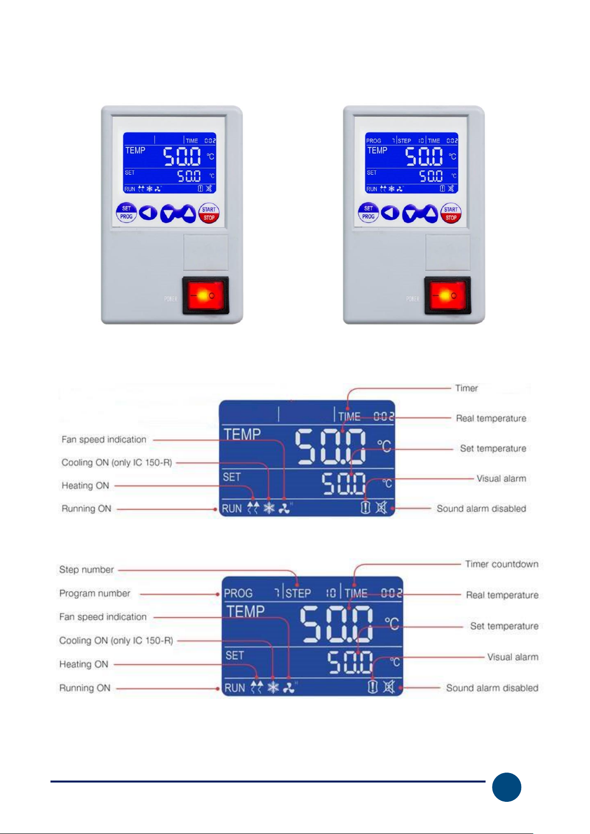
Picture 2 – BASIC version
Picture 3 - PROFESSIONAL (PRO) version
Picture 4 – Display BASIC version
Picture 5 - Display PROFESSIONAL (PRO) version
Page 5
Ver. 1.1 – 14/05/2015
3
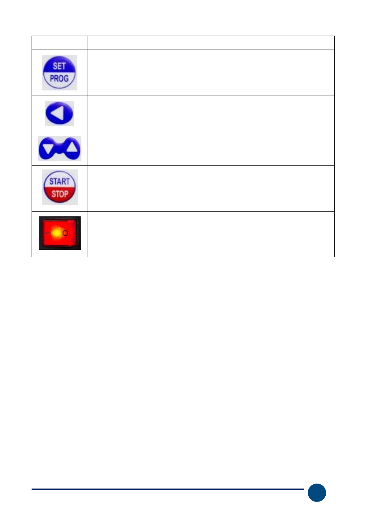
COMMANDS
DESCRIPTION
The SET/PROG button permits the working parameters setting and to
enter/escape from the programs (PRO version only).
In combination with the SHIFT key allows access to menus with password (see
paragraph 6.4).
The SHIFT button permits to change quickly the digit (decimal, units, tens, etc.)
of the value of the parameter you are editing.
In combination with the SET/PROG key allows access to menus with password
(see paragraph 6.4).
Adjustment buttons allow you to increase or decrease the value of the
operating parameter being edited.
The START / STOP button permits to start / stop a cycle operation or a
program (PRO version only).
The ON/OFF button allows to turn on and turn off the instrument.
5 Instrument versions
The instruments are sold in two versions: BASIC (without programming) and PROFESSIONAL
(with programming).
Depending the purchased version please follow this manual in the appropriate sections:
- BASIC (paragraph 6 at page 4)
- PROFESSIONAL (paragraph 7 at page 9)
Page 6
Ver. 1.1 – 14/05/2015
4
6 Operation (Basic version)
6.1 Switching on the instrument
Connect the power cord to a power outlet with a protective ground connection.
Turn on the instrument by pressing the button ON / OFF. Button and the display will light up.
The display shows the initialization sequence and then the instrument is ready for use.
NOTE: every time you turn the instrument beeps intermittently, the icon of visual alarm and the
word “end” appear on the display, indicating that a heating cycle had been done before. Press any
button to silence the audible signal and the icon appears.
6.2 Setting of parameters
6.2.1 Working temperature
When the instrument is switched on, pressing one time the SET/PROG button, the set
temperature value starts to blink.
Set the desired temperature value (in Celsius degrees) pressing keys.
It’s possible a quick movement between the digits using the SHIFT button.
Confirm the set value with another press of SET/PROG button.
6.2.2 Working time
After confirming the temperature, the last value of the set time (timer) starts flashing.
Set the desired value (hh:mm) by pressing keys. It’s possible a quick movement between the
digits using the SHIFT button.
Confirm the set value with another press of SET/PROG button.
NOTE: the value “00:00” indicates the operating mode "continuous", that means once you start
the operating cycle by the START / STOP button, it continues maintaining the set temperature
until it is stopped manually (START/STOP ).
If you set a value of time, such as 1 hour, the instrument will reach the set temperature and will
maintain it for an hour.
6.2.3 Fan speed (forced air instruments only)
After confirming the desired timer, the icon starts to blink indicate the last level of fan speed
selected H = High (100%), M = Medium (75%), L = Low (50%). Set the desired level by pressing
the keys .
Confirm the set value with another press of SET/PROG button.
Page 7
Ver. 1.1 – 14/05/2015
5
6.3 Start/stop heating cycle
After setting the operating parameters, pressing START / STOP button with long pressure (4-5
seconds), the heating cycle starts for the defined time in hh:mm or continuous (00:00). The word
“end” at the top right corner of display disappears, the message RUN appears in the bottom left
corner and display shows contemporary: timer, temperature measured inside the chamber, set
temperature and fan speed if present (see Picture 4Picture 4).
At any time you can always manually stop the cycle by pressing the START / STOP button
with long pressure (4-5 seconds).
Once the set time or after manual stop, the instrument beeps intermittently, the icon of visual alarm
and the word "end" appear on the display. Pressing any button it’s possible to silence the
audible signal and the icon appears.
NOTE: the acoustic signal will not end until it is stopped by the operator, but the heating cycle is
terminated so for the samples inside the instrument will remain exposed to the internal temperature
the chamber.
6.4 Functions with password access
6.4.1 Access to menu with password
Simultaneously pressing the SET / PROG and SHIFT for few seconds, you can access
some functions and parameters that are password protected.
To access these submenus and avoid mistakenly entering in the operating parameters setting, it is
recommended to firstly press the SHIFT key, keep it pressed, and then press the SET / PROG
for few seconds.
After have made this keys combination, on the right top part of display instead of word TIME, “Lk”
(lock) appears close to “0000” (password).
Below the passwords and access sequence to the various parameters/functions.
PASSWORD
FUNCTION/
PARAMETER
DESCRIPTION
0000
dy
Delay of heating cycle start
0003
tm
Safety temperature limiter for samples protection
Po
Restart mode after absence of power supply
AL
Temperature range for over temperature alarm
Pb
Temperature offset on single point
PK
Temperature offset on the entire ramp
PA
Temperature offset of the room temperature probe
6.4.2 Delay of heating cycle start
It’s possible to set a delay (hour and minutes) of heating cycle start.
Please follow the instructions reported at paragraph 6.4.1 and confirm the“0000” password
pressing shortly one time SET/PROG .
On the top right part of display the parameter “dy” (delay) appears close to value 00:00.
Page 8
Ver. 1.1 – 14/05/2015
6
Set the desired delay value (hh:mm) pressing keys. It’s possible a quick movement between
the digits using the SHIFT button. Confirm the set value with another press of SET/PROG
button.
The display comes back to the standby screen (see Picture 4).
Pressing the START/STOP button with long pressure (4-5 seconds) the instrument starts the
work cycle but it doesn’t immediately heat: the word “end” and the set delay time alternately blink
on the top right part of display, counting the wait time until the real starting of heating.
Once the delayed time is passed the instrument starts to heat and the regular timer appears on
display.
6.4.3 Safety temperature limiter for samples protection
The instrument has the possibility to limit the maximum work temperature for the samples
protection from an erroneous setting of the working temperature.
Please follow the instructions reported at paragraph 6.4.1 and using the keys set the “0003”
password. It’s possible a quick movement between the digits using the SHIFT button.
Confirm the set value with another press of SET/PROG button.
On the top right part of display the parameter “tm” (temperature max) and the maximum expected
value for the kind of instrument (different for oven and incubator) appear.
Set the maximum temperature value you want the instrument doesn’t exceed during work cycle by
the keys. It’s possible a quick movement between the digits using the SHIFT button.
Confirm the set value with another press of SET/PROG button.
Example
If the set temperature for the work cycle is 100 °C and the safety temperature is fixed at 70°C, the
instrument tries to achieve the set temperature (100°C), even if it’s major than the safety
temperature set in this menu (tm).
When the 70 degrees are achieved the instrument goes in alarm emitting an audible intermittent
alarm (silence it pressing any keys) and the heating element doesn’t receive power supply until to
the temperature will go below the safety temperature (tm).
NOTE: the instrument tries in any moment to achieve the set work temperature; as a consequence,
until it is bigger than the safety temperature (tm), it goes in over temperature alarm as described in
the previous paragraph.
6.4.4 Restart mode after absence of power supply
It’s possible to set the restart mode of the instrument after a power supply absence:
Po VALUE
DESCRIPTION
0
On return of the power supply, the instrument does not automatically resume the
heating cycle, but you must manually restart.
1
On return of the power supply, the instrument automatically resumes operation
from the beginning of the heating cycle interrupted
2
On return of the power supply, the instrument automatically resumes operation at
the very point of the heating cycle in which it was interrupted
Page 9

Ver. 1.1 – 14/05/2015
7
Please follow the instructions reported at paragraph 6.4.1 and using the keys set the “0003”
password. It’s possible a quick movement between the digits using the SHIFT button.
Confirm the set value with another press of SET/PROG button.
On the top right part of display the parameter “tm” (temperature max), pass to the next parameter
“Po” (Power) pressing shortly SET/PROG .
Confirm pressing shortly another time SET/PROG . Set the desidered value (0, 1, 2) pressing
the keys. Confirm pressing shortly SET/PROG .
6.4.5 Temperature range for over temperature alarm
The instrument has the opportunity to set the range of temperature over which it goes in over
temperature alarm.
NOTE: even if this value is adjustable by the operator, it’s already set by factory and perfectly
calibrated in function of instrument type, natural/forced air oven or incubator.
We recommend to do not change this value unless absolutely necessary, because temperature
fluctuations more or less than the set one, especially in models with natural convection, are normal
and thus reducing dramatically the value of AL, it would risk do go frequently and unnecessarily
alarmed the instrument.
Please follow the instructions reported at paragraph 6.4.1 and using the keys set the “0003”
password. It’s possible a quick movement between the digits using the SHIFT button.
Confirm the set value with another press of SET/PROG button
On the top right part of display the parameter “tm” (temperature max), pass to the next parameters
pressing shortly SET/PROG more times.
Find the parameter AL (alarm), set the minimum temperature value above which you want the
instrument goes in alarm pressing the keys. It’s possible a quick movement between the
digits using the SHIFT button. Confirm the set value with another press of SET/PROG
button.
6.4.6 Temperature offset on single point, on entire ramp, on room temperature
sensor
The instrument has the opportunity to set the offset value on a single temperature point, on the
entire temperature ramp and on the room temperature sensor.
NOTE: even if these values are adjustable by the operator, they are already set by factory and
perfectly calibrated with certified and referable Accredia measurement instruments.
We recommend that you do not change these values unless absolutely necessary, for example if
after a check with digital certified thermometer you find a discrepancies between the reading of the
instrument and the external thermometer.
Please follow the instructions reported at paragraph 6.4.1 and using the keys set the “0003”
password. It’s possible a quick movement between the digits using the SHIFT button.
Confirm the set value with another press of SET/PROG button
Page 10

Ver. 1.1 – 14/05/2015
8
On the top right part of display the parameter “tm” (temperature max), pass to the next parameters
pressing shortly SET/PROG more times.
PARAMETER
DESCRIPTION
Pb
Changing this parameter you can correct the reading of PT100 sensor inside the
instrument on one point temperature. The correction will therefore be attributable
to one specific point.
PK
Changing this parameter you can correct the reading PT100 sensor inside the
instrument over the entire temperature ramp, that is going to change the
inclination of the ramp reading of the sensor.
PA
Changing this parameter you can correct the reading of environmental PT100
sensor installed on the instrument (only refrigerated versions) on only one
temperature point. The correction will therefore be attributable to one specific
point.
Page 11

Ver. 1.1 – 14/05/2015
9
7 Operation (Professional version)
7.1 Switching on the instrument
Connect the power cord to a power outlet with a protective ground connection.
Turn on the instrument by pressing the button ON / OFF. Button and the display will light up.
The display shows the initialization sequence and then the instrument is ready for use.
NOTE: every time you turn the instrument beeps intermittently, the icon of visual alarm and the
word “end” appear on the display, indicating that a heating cycle had been done before. Pressi
any button to silence the audible signal and the icon appears.
7.2 Programming
In the Professional version the instrument can manage until 7 programs with 10 steps each one in
which temperature, timer and fan speed (if present) are settable.
Moreover them, it’s possible to set a simple work cycle at single work step, with temperature, timer
and fan speed (if present). This is called “PROG 0” and it is equivalent what the instrument does in
the Basic version.
7.2.1 Calling programs
When the instrument is switched on, in standby or during a work cycle both, pressing shortly one
time the SET/PROG button, the word “PROG” and the program number (see Picture 5) start to
blink together.
Calling the desired program by the keys. Confirm pressing shortly one time the SET/PROG
button. The selected program is ready to start.
7.2.2 Modify a program
To modify a program it’s necessary keep pressed for few seconds the SET/PROG button: the
word “PROG” and the program number start to blink together and after some moment only the
program number blinks.
Now it’s possible to choose the desired program to be modified by the keys and to confirm it
by a short press of SET/PROG button.
Then the instrument enters in the modification mode and the temperature value of the first step
blinks together the word “PROG” to indicate that you are in programming phase.
STEP 1
Set by the and SHIFT keys the temperature value of the first step. Press shortly
SET/PROG to confirm it and pass to the next value (timer), always of the first STEP. Set by the
and SHIFT keys the desired timer value of the first step and confirm by a short press of
SET/PROG .
If the instrument is a forced air model, the next parameter to be set is the fan speed, adjustable by
the keys in (H=High, M=Medium, L=Low), otherwise you pass to STEP 2.
STEP 2
Page 12

Ver. 1.1 – 14/05/2015
10
Set by the and SHIFT keys the temperature value of the second step. Press shortly
SET/PROG to confirm it and pass to the next value (timer), always of the second STEP. Set by
the and SHIFT keys the desired timer value of the second step and confirm by a short
press of SET/PROG .
If the instrument is a forced air model, the next parameter to be set is the fan speed, adjustable by
the keys in (H=High, M=Medium, L=Low), otherwise you pass to STEP 3.
REPEAT THE ABOVE INSTRUCTIONS FOR EVERY STEP YOU WANT TO PROGRAM
NOTE: if you do not want to use all 10 STEP of the program you are editing, it is necessary to
communicate to the instrument the end of the program. To do this, simply set in the next step after
the last step you want to use the time equal to "00:00".
EXAMPLE
If the last work step you want to use is the fifth, it’s sufficient set in the sixth step the timer equal to
“00:00”, imposing in this way to the instrument to stop it at the end of the fifth step.
NOTE: to modify the program 0, recall it as explained in paragraph 7.2.1 and proceed to the
various parameters (temperature, timer and fan speed when present) as shown in paragraph 6.2 of
the Basic version.
7.3 Start/stop of a program
After setting the program, simply call one of them and press the START / STOP with long
pressure (4-5 seconds) to start the selected program.
The word "end" at the top right of the display disappears, the message RUN appears on bottom left
part and display shows simultaneously: program number, step in progress, timer, measured
temperature inside the chamber, set temperature and fan speed if present (see Picture 5).
At any time you can always manually stop the cycle by pressing the START / STOP button
with long pressure (4-5 seconds).
Once the set program is finished or after a manual stop, the instrument beeps intermittently, the
icon of visual alarm and the word “end” appear on the display. Pressing any button will silence
the audible signal and the icon appears.
NOTE: the acoustic signal will not end until it is stopped by the operator, but the heating cycle is
terminated so for the samples inside the instrument will remain exposed to the internal temperature
the chamber.
7.4 Functions with password access
7.4.1 Access to menu with password
Simultaneously pressing the SET / PROG and SHIFT for few seconds, you can access
some functions and parameters that are password protected.
Page 13
Ver. 1.1 – 14/05/2015
11
To access these submenus and avoid mistakenly entering in the operating parameters setting, it is
recommended to firstly press the SHIFT key, keep it pressed, and then press the SET / PROG
for few seconds.
After have made this keys combination, on the right top part of display instead of word TIME, “Lk”
(lock) appears close to “0000” (password). Below the passwords and access sequence to the
various parameters/functions.
PASSWORD
FUNCTION/
PARAMETER
DESCRIPTION
0000
Pn
Number of program to which to apply the dy e Cy functions
Cy
Number of repetitions of the work cycle
dy
Partenza ritardata del programma selezionato
0003
tm
Safety temperature limiter for samples protection
Po
Restart mode after absence of power supply
AL
Temperature range for over temperature alarm
Pb
Temperature offset on single point
PK
Temperature offset on the entire ramp
PA
Temperature offset of the room temperature probe
7.4.2 Number of program to which apply the Delay and Cycle functions
On the contrary of the Basic version that doesn’t have more programs but a unique work cycle, in
the Professional version it’s necessary to define to which program (from 1 to 7) apply the functions
of starting delayed (Delay) and repetition of cycle (Cycle).
To do that it’s necessary enter in the first submenu with password access (0000) and modify the
parameter Pn (program number) by keys and confirm the selected program by a short press
of SET/PROG button.
7.4.3 Ripetition of a program
The instrument allows the repeating from one to more times of the selected program. After have
chosen the program to which apply the function by the parameter Pn it’s possible set the Cy value
(Cy)= 1, 2, 3,...with keys and SHIFT and confirm it pressing shortly SET/PROG .
NOTE: it’s also possible set the continuous repetition of a program, setting it in continuous “loop”,
with the parameter Cy=0.
7.4.4 Delay of the program start
It’s possible to set a delay (hour and minutes) of the program start.
After have chosen the program to which apply the function by the parameter Pn it’s possible set
the desired delay value (hh:mm) pressing keys. It’s possible a quick movement between the
digits using the SHIFT button. Confirm the set value with another press of SET/PROG
button. The display comes back to the standby screen (see Picture 5). Pressing the START/STOP
button with long pressure (4-5 seconds) the instrument starts the program but it doesn’t
immediately heat: the word “end” and the set delay time alternately blink on the top right part of
display, counting the wait time until the real starting of the program.
Once the delayed time is passed the instrument starts to heat and the regular timer appears on
display.
Page 14
Ver. 1.1 – 14/05/2015
12
7.4.5 Safety temperature limiter for samples protection
The instrument has the possibility to limit the maximum work temperature for the samples
protection from an erroneous setting of the working temperature.
Please follow the instructions reported at paragraph 6.4.1 and using the keys set the “0003”
password. It’s possible a quick movement between the digits using the SHIFT button.
Confirm the set value with another press of SET/PROG button.
On the top right part of display the parameter “tm” (temperature max) and the maximum expected
value for the kind of instrument (different for oven and incubator) appear.
Set the maximum temperature value you want the instrument doesn’t exceed during work cycle by
the keys. It’s possible a quick movement between the digits using the SHIFT button.
Confirm the set value with another press of SET/PROG button.
Example
If the set temperature for the work cycle is 100 °C and the safety temperature is fixed at 70°C, the
instrument tries to achieve the set temperature (100°C), even if it’s major than the safety
temperature set in this menu (tm).
When the 70 degrees are achieved the instrument goes in alarm emitting an audible intermittent
alarm (silence it pressing any keys) and the heating element doesn’t receive power supply until to
the temperature will go below the safety temperature (tm).
NOTE: the instrument tries in any moment to achieve the set work temperature; as a consequence,
until it is bigger than the safety temperature (tm), it goes in over temperature alarm as described in
the previous paragraph.
7.4.6 Restart mode after absence of power supply
It’s possible to set the restart mode of the instrument after a power supply absence:
Po VALUE
DESCRIPTION
0
On return of the power supply, the instrument does not automatically resume the
heating cycle, but you must manually restart.
1
On return of the power supply, the instrument automatically resumes operation
from the beginning of the heating cycle interrupted
2
On return of the power supply, the instrument automatically resumes operation at
the very point of the heating cycle in which it was interrupted
Please follow the instructions reported at paragraph 6.4.1 and using the keys set the “0003”
password. It’s possible a quick movement between the digits using the SHIFT button.
Confirm the set value with another press of SET/PROG button.
On the top right part of display the parameter “tm” (temperature max), pass to the next parameter
“Po” (Power) pressing shortly SET/PROG .
Confirm pressing shortly another time SET/PROG . Set the desidered value (0, 1, 2) pressing
the keys. Confirm pressing shortly SET/PROG .
Page 15
Ver. 1.1 – 14/05/2015
13
7.4.7 Temperature range for over temperature alarm
The instrument has the opportunity to set the range of temperature over which it goes in over
temperature alarm.
NOTE: even if this value is adjustable by the operator, it’s already set by factory and perfectly
calibrated in function of instrument type, natural/forced air oven or incubator.
We recommend to do not change this value unless absolutely necessary, because temperature
fluctuations more or less than the set one, especially in models with natural convection, are normal
and thus reducing dramatically the value of AL, it would risk do go frequently and unnecessarily
alarmed the instrument.
Please follow the instructions reported at paragraph 6.4.1 and using the keys set the “0003”
password. It’s possible a quick movement between the digits using the SHIFT button.
Confirm the set value with another press of SET/PROG button
On the top right part of display the parameter “tm” (temperature max), pass to the next parameters
pressing shortly SET/PROG more times.
Find the parameter AL (alarm), set the minimum temperature value above which you want the
instrument goes in alarm pressing the keys. It’s possible a quick movement between the
digits using the SHIFT button. Confirm the set value with another press of SET/PROG
button.
7.4.8 Temperature offset on single point, on entire ramp, on room temperature
sensor
The instrument has the opportunity to set the offset value on a single temperature point, on the
entire temperature ramp and on the room temperature sensor.
NOTE: even if these values are adjustable by the operator, they are already set by factory and
perfectly calibrated with certified and referable Accredia measurement instruments.
We recommend that you do not change these values unless absolutely necessary, for example if
after a check with digital certified thermometer you find a discrepancies between the reading of the
instrument and the external thermometer.
Please follow the instructions reported at paragraph 6.4.1 and using the keys set the “0003”
password. It’s possible a quick movement between the digits using the SHIFT button.
Confirm the set value with another press of SET/PROG button
On the top right part of display the parameter “tm” (temperature max), pass to the next parameters
pressing shortly SET/PROG more times.
PARAMETER
DESCRIPTION
Pb
Changing this parameter you can correct the reading of PT100 sensor inside the
instrument on one point temperature. The correction will therefore be attributable
to one specific point.
PK
Changing this parameter you can correct the reading PT100 sensor inside the
instrument over the entire temperature ramp, that is going to change the
Page 16

Ver. 1.1 – 14/05/2015
14
inclination of the ramp reading of the sensor.
PA
Changing this parameter you can correct the reading of environmental PT100
sensor installed on the instrument (only refrigerated versions) on only one
temperature point. The correction will therefore be attributable to one specific
point.
8 Clean and maintenance
Proper maintenance and cleaning of the instrument guarantee its good conditions.
The inner chamber of the instrument is made of stainless steel, so it can be cleaned with any
detergent provided it is not aggressive and / or corrosive.
You should clean the inside and outside surfaces with a standard all-purpose cleaner sprayed on a
soft cloth.
Before proceeding with any cleaning or decontamination, the user must ensure that the method
used does not damage the instrument.
IMPORTANT:
If the instrument must be returned for service, it is necessary to provide for proper cleaning and
possible decontamination by pathogens of the same.
It is also recommended to put the instrument in its original packaging to send it in for repairs and if
it is missed it is necessary to provide to pack it properly in order to the transport.
Any damage caused from the incorrect shipping will not be covered by warranty.
9 Disposal of electronic equipment
The electrical and electronic equipment marked with this symbol may not be
disposed of in landfills.
In accordance with EU Directive 2002/96/EC, the European users of
electrical and electronic equipment have the opportunity to give back to the
distributor or manufacturer upon purchase of a new one.
The illegal disposal of electrical and electronic equipment is punished with an administrative fine.
Page 17

Ver. 1.1 – 14/05/2015
15
Technical Specifications
Natural convection oven
TIN-TN30
TIN-TN50
TIN-TN115
TIN-TN200
Usable Volume
30 Liters
50 Liters
115 Liters
200 Liters
Max. Temperature/Resolution
+200/0,1°C
+300/0,1°C
+300/0,1°C
+300/0,1°C
Temperature homogeneity at
150°C
±3,5°C
±3,5°C
±3,5°C
±4°C
Temperature variation at 150°C
±0,5°C
±0,5°C
±0,5°C
±0,7°C
Heating time at 150°C (min)
20
24
30
50
Timer
99:59/
continuous
operation
99:59/ continuous
operation
99:59/ continuous
operation
99:59/ continuous
operation
Internal Dimension (WxHxD) in
mm
320 x 320 x 285
400 x 420 x 330
520 x 495 x 450
650 x 640 x 495
No. of shelves (standard/max)
2/4
2/5
2/6
2/9
Min. distance between shelves
50mm
50mm
50mm
50mm
Max. load of shelves (kg)
10
15
20
20
Voltage/Power
230V/700W
230V/1000W
230V/1900W
230V/2100W
External Dimension (WxHxD) in
mm
460 x 660 x 530
660 x 630 x 470
790 x 750 x 600
915 x 905 x 600
Weight (kg)
40
53
74
103
Safety class
3.1
3.1
3.1
3.1
Forced Air oven
TIN TF-50
TIN-TF120
TIN-TF200
TIN-TF400
Volume
50 Liters
120 Liters
200 Liters
400 Liters
Max. Temperature/Resolution
+300/0,1°C
+300/0,1°C
+300/0,1°C
+300/0,1°C
Temp. homogeneity at 150°C
±2%
±2%
±2%
±2%
Temperature variation at 150°C
±0,3°C
±0,3°C
±0,4°C
±0,5°C
Heating time at 150°C (min)
14
16
18
20
Timer
99:59/continuous
operation
99:59/continuous
operation
99:59/continuous
operation
99:59/continuous
operation
Int. Dimension (WxHxD) in mm
400 x 415 x 310
520 x 530 x 435
645 x 650 x 495
1000 x 800 x 500
No. of shelves (standard/max)
2/5
2/7
2/9
2/10
Min. distance between shelves
50mm
50mm
50mm
50mm
Max. load of shelves (kg)
15
20
20
20
Voltage/Power
230V/980W
230V/1900W
230V/2400W
230V/3200W
Ext.Dimension (WxHxD) in mm
665 x 635 x 570
785 x 750 x 690
920 x 870 x 755
1260 x 1060 x 750
Weight (kg)
54
74
103
160
Safety class
3.1
3.1
3.1
3.1
Page 18

Ver. 1.1 – 14/05/2015
16
Incubators
TIN-IN16
TIN-IN35
TIN-IN55
Volume
16 Liters
35 Liters
55 Liters
Max. Temperature/Resolution
+70/0,1°C
+70/0,1°C
+70/0,1°C
Temp. homogeneity at 37°C
±0,4°C
±0,4°C
±0,5°C
Temperature variation at 37°C
±0,3°C
±0,3°C
±0,3°C
Heating time at 37°C (min)
18
22
25
Timer
99:59/continuous
operation
99:59/continuous
operation
99:59/continuous
operation
Int. Dimension (WxHxD) in mm
270 x 230 x 255
360 x 300 x 320
400 x 360 x 385
No. of shelves (standard/max)
2/6
2/6
2/5
Min. distance between shelves
25mm
30mm
50mm
Max. load of shelves (kg)
5
7,5
10
Voltage/Power
230V/85W
230V/125W
230V/250W
Ext. Dimension (WxHxD) in mm
505 x 370 x 400
595 x 440 x 460
635 x 500 x 545
Weight (kg)
23
33
42
Safety class
2 2 2 Incubators
TIN-IN120
TIN-IN200
Volume
120 Liters
200 Liters
Max. Temperature/Resolution
+70/0,1°C
+70/0,1°C
Temp. homogeneity at 37°C
±0,5°C
±0,5°C
Temperature variation at 37°C
±0,3°C
±0,3°C
Heating time at 37°C (min)
30
35
Timer
99:59/continuous
operation
99:59/continuous
operation
Int. Dimension (WxHxD) in mm
520 x 460 x 500
610 x 600 x 575
No. of shelves (standard/max)
2/7
2/9
Min. distance between shelves
50mm
50mm
Max. load of shelves (kg)
10
10
Voltage/Power
230V/350W
230V/600W
Ext. Dimension (WxHxD) in mm
755 x 610 x 645
850 x 755 x 710
Weight (kg)
61
77
Safety class
2
2
Page 19

Ver. 1.1 – 14/05/2015
17
Service
When help needed, please contact your local distributor our the service department
of Phoenix Instrument GmbH for technical support in the following ways:
Phoenix Instrument GmbH
Heinkelstraße 10
30827 Garbsen
05131/9081830
[email protected]
Phoenix Instrument GmbH – Heinkelstraße 10 – 30827 Garbsen
Telefon 05131 90818-30 – [email protected]
 Loading...