

Page 1

POWERFUL AND COMPACT, CLASS D AMPLIFIERS
ZR
• High Level Auto-Turn On - powers on the amp when audio signal is supplied
• OEM Connection Ready - compatible with aftermarket/original source units
• Remote Bass Ready - control bass with included ZRBC (ZR10001 & ZR20001)
Model: ZR6004 / ZR10001 / ZR20001
SPECIFICATIONS
• Fanless Design - regulates temperature internally for quiet operation
• High & Low Level Inputs - versatile connectivity to suit any vehicle
• Heavy Duty Connector Block - enables maximum current supply
• 4-Way Protected Circuit - protection against thermal damage,
reversed power, speaker polarity and low voltage
All specications subject to change without notice.
© 2021 Phoenix Gold • www.phoenixgold-eu.com
Page 2

ZR6004 / ZR10001 / ZR20001 - ZR-Series Ampliers
ZR6004 ZR10001 ZR20001
Class
Frequency
Response
Dims (LxWxH(mm))
RMS Power
Ratings
Signal to
Noise Ratio
High & Low Pass
Crossover
Subsonic Filter
Crossover
Range
Subsonic
Crossover Range
Bass Boost
@ 45Hz
Low Level
Input Range
High Level
Input Range
Minimum Load
Impedance
Class D Class D Class D
20Hz-20KHz 20Hz-400Hz 20Hz-400Hz
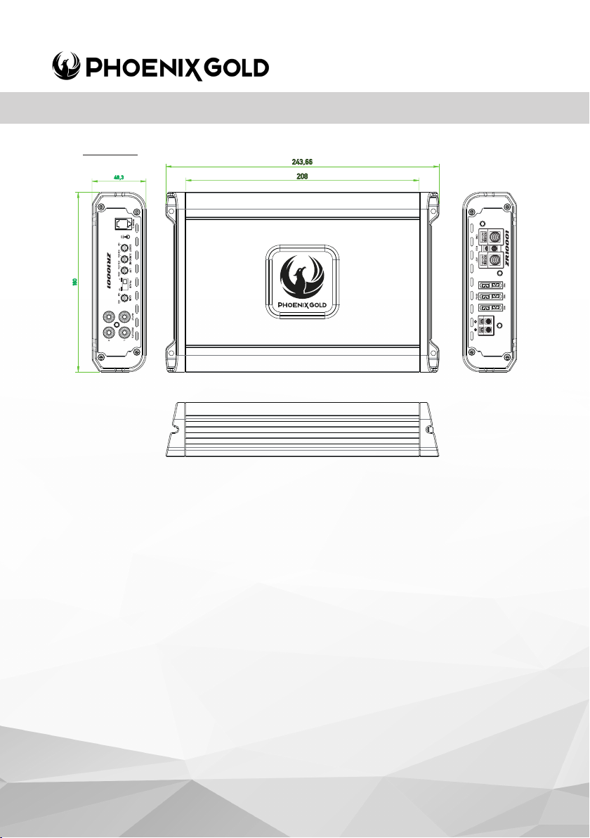
253 x 160 x 48 243 x160 x 48 383 x 160 x 48
175W x 4 @ 2ohm
105W x 4 @ 4ohm
350W x 2 @ 4ohm
bridged
>96dB >96dB >96dB
12dB per Octave 24dB per Octave 24dB per Octave
N/A 12dB per Octave 12dB per Octave
40Hz-6KHz 50Hz-250Hz 50Hz-250Hz
N/A 10Hz-55Hz 10Hz-55Hz
N/A 0 to +18dB 0 to +18dB
0.2V to 10V 0.2V to 10V 0.2V to 10V
1V to 30V 1V to 30V 1V to 30V
2ohm stereo &
4ohm bridged
1015W x 1 @ 1ohm
670W x 1 @ 2ohm
385W x 1 @ 4ohm
1ohm 1ohm
2015W x 1 @ 1ohm
1310W x 1 @ 2ohm
740W x 1 @ 4ohm
Note:
Phoenix Gold Ampliers have a minimum load impedance
of 2ohm per channel 4ohm bridged
© 2021 Phoenix Gold | A Brand of AAMP Global
www.phoenixgold-eu.com
Page 3

ZR6004 / ZR10001 / ZR20001 - ZR-Series Ampliers
Installation Warnings
1. Ensure the +12V lead is disconnected from the battery before you
connect any new equipment
2. Ensure that the amplier mounting location and holes will not interfere
with the petrol tank, brake lines or electrical wiring.
3. Ensure the amplier is securely fastened to the vehicle to prevent the
amplier moving and causing damage in the event of an accident
4. Ensure all wiring is protected from sharp objects and from pinching or
crushing which could result in damage to the audio system
5. Ensure the mounting location has sufcient air ow around the
amplier. If the amplier is mounted in an enclosed space a 3” fan
with ducting should be used to assist with cooling.
6. Do not mount any amplier on a subwoofer enclosure as extended
exposure to vibration may cause damage to the amplier.
7. Ensure the minimum recommended gauge wire/cable or larger for all
amplier connections
8. Appropriate mounting is very important for prolonged life
expectancy of any amplier. Select a location that provides
protection from moisture. Keep in mind that an amplier should never
be mounted upside down. Upside down mounting will compromise
heat dissipation through the heat sink and could engage the thermal
protection circuit.
© 2021 Phoenix Gold • www.phoenixgold-eu.com
Page 4
ZR6004 / ZR10001 / ZR20001 - ZR-Series Ampliers
Connection
Ensure the audio system is turned off before making any connections to the
amplier, speakers or source unit. Failure to do so could result in permanent
damage to the audio system.
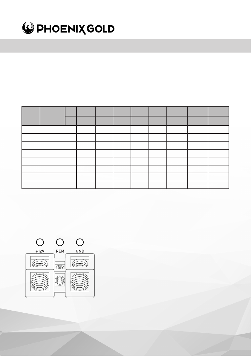
Ensure the correct gauge cable is used for all connections; consult the cable
calculator diagram below for the correct gauge cable for your installation.
Total
Amps
0-20 14 12 12 10 10 8 8 8
20-35 12 10 8 8 6 6 6 4
35-50 10 8 8 6 4 4 4 4
50-65 8 8 6 4 4 4 4 2
65-85 6 6 4 4 2 2 2 0
85-105 6 6 4 2 2 2 2 0
105-125 4 4 4 2 0 0 0 0
125-150 2 2 2 0 0 0 0 0
Cable
Length >
M 0-1 1-2 2-3 3-4 4-5 5-6 6-7 7-9
FT 0-4 4-7 7-10 10-13 13-16 16-19 19-22 22-28
The above chart shows cable gauges to be used if no less than a 0.5V drop is acceptable.
If aluminium wire is used, the gauges should be of an even larger size to compensate.
Cable gauge size calculation takes into account terminal connection resistance.
AMPLIFIER CONNECTION
1. +12V Power
Ensure ALL other cable connections are completed
1 2 3
© 2021 Phoenix Gold | A Brand of AAMP Global
before connecting this cable to the battery. PHOENIX
GOLD ampliers should be connected directly to the
12V battery terminal using the appropriate gauge cable.
Start at the vehicles battery and run the cable through
to the amplier. PHOENIX GOLD recommends the use
of rubber grommets when passing any cable through
metal panels to avoid sharp corners or panels that could
cut through the insulation of the cable. An inline fuse or
circuit breaker MUST be used within 30cm (12”) of your
battery; this will prevent the potential risk of a re caused
by a short in your power cable (see spec table for
recommended inline fuse/circuit breaker ratings).
Connect the other end of your power cable to the
battery, but remember to leave the fuse out or circuit
breaker off until all other cable connections are made.
www.phoenixgold-eu.com
Page 5
ZR6004 / ZR10001 / ZR20001 - ZR-Series Ampliers
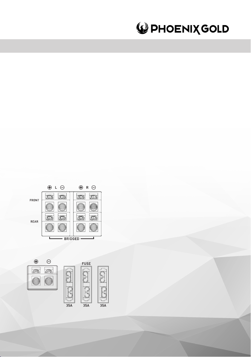
2. Remote Turn-On
This connection turns the amplier on and should be connected to the ‘Remote Turn on’
wire from the Head Unit. If one is not available a switched +12V source must be used,
such as a power antenna wire or ACC +12V.
If you are using high level (speaker) inputs and a remote turn on wire is not available, then
instead the ‘Auto Turn-On’ switch must be set to ON.
3. Ground
Connect the Ground/Earth cable for your amplier rst. Ensure that the location is a good
source of ground (preferably the chassis/oor pan). Investigate the area you wish to use
to ensure it is free of wiring, vacuum lines, brake and fuel lines. Use either a wire brush or
sandpaper to expose bare metal, this will provide a high current contact for your ground
connection. Use the same gauge cable for the ground cable as you did for the power
cable. Secure the ground cable to the ground point with a bolt, star washer and nut.
Apply some neutral cure silicon to the bolt and bare metal to prevent possible water
leaks and rust. Connect the other end of your ground cable to the amplier.
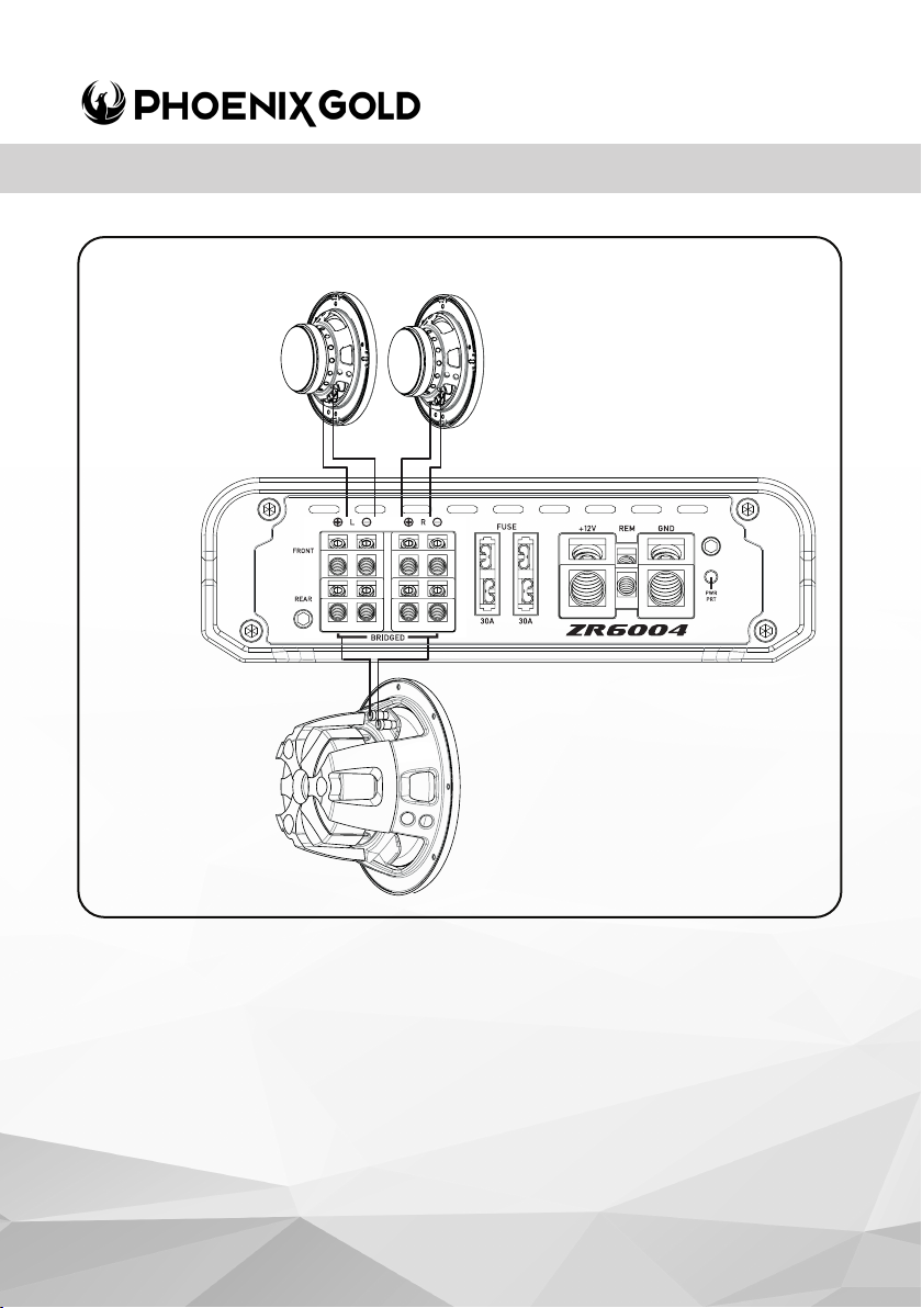
4A. Speaker Output Connection
(ZR6004 ONLY)
Ensure the correct polarity is observed when connecting
speakers/subwoofers.
2ohm minimum speaker impedance for stereo
operation (per channel).
4ohm minimum speaker impedance for bridged
operation.
4B. Internally Linked Output
(ZR10001 - ZR20001)
The ZR20001 Monoblock amplier provides dual output
connections to simplify wiring when using 2 subwoofers
or a dual voice coil subwoofer. Both positive and
negative terminals and internally connected or linked
in parallel. For dual coil (2 x 4ohm) or two single coil
(4 ohm) subwoofers connect each coil to positive or
negative terminal. For a standard single coil subwoofer
connect to either positive and either negative terminal.
© 2021 Phoenix Gold • www.phoenixgold-eu.com
Page 6
ZR6004 / ZR10001 / ZR20001 - ZR-Series Ampliers
ZR6004
Example of 3 Channel
conguration
2 x Front/Rear Speakers
(4Ohm Subwoofer)
Bridged Rear Channels
© 2021 Phoenix Gold | A Brand of AAMP Global
www.phoenixgold-eu.com
Page 7
ZR6004
ZR6004 / ZR10001 / ZR20001 - ZR-Series Ampliers
ZR10001/
ZR20001
12
7 799
14
11 10
66
5
13
8
6
5
© 2021 Phoenix Gold • www.phoenixgold-eu.com
Page 8

ZR6004 / ZR10001 / ZR20001 - ZR-Series Ampliers
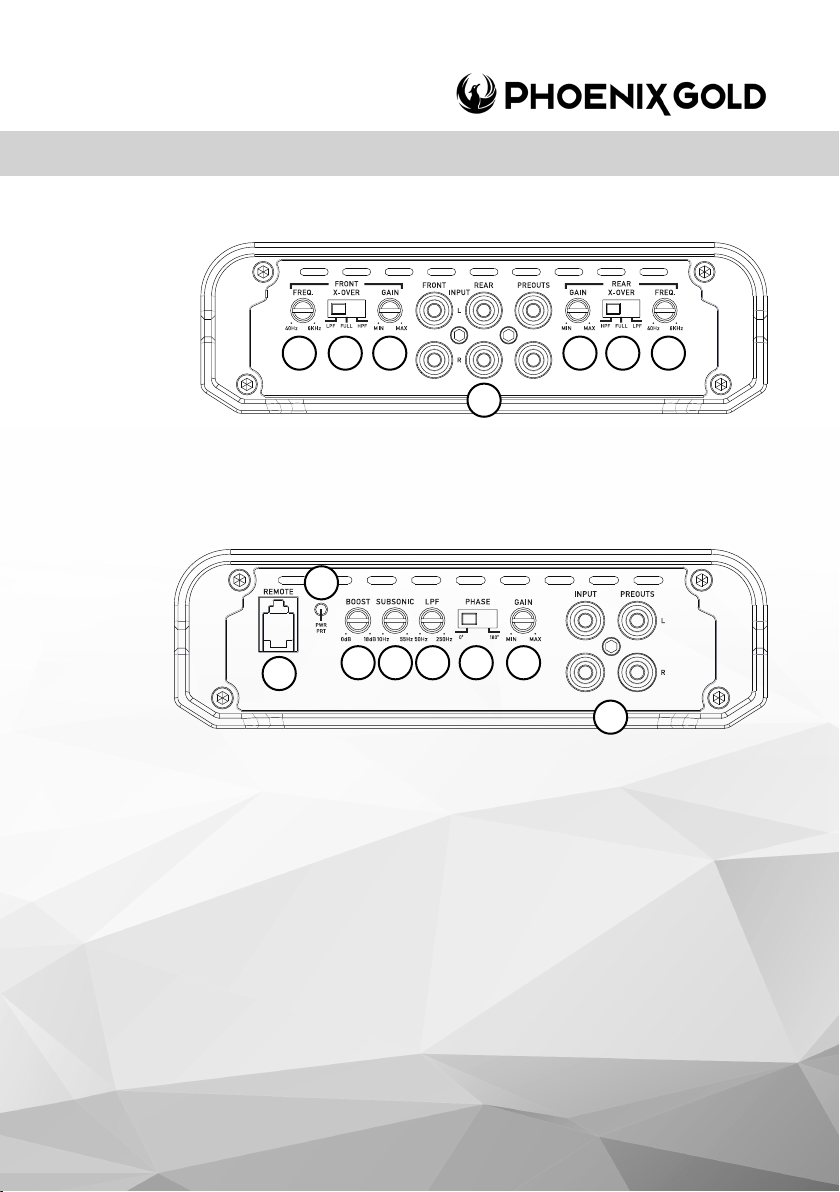
5. RCA Inputs Front-Rear-Subwoofer
Choose the correct length RCA cables to connect the RCA outputs of the source/head
unit, to the input connectors of the amplier. The RCA inputs also accept ‘high level
input’, when using a high level signal, the amplier will autostart without the need of a
remote signal.
Run the RCA cables on the opposite side of the vehicle. to the power cable and vehicle
wiring loom. Avoid the electric fan motor and wiring. Ensure you follow the correct
balance. (L LEFT = White or Black. R Right = Red)
6. Gain/Level Control (Sub/Front/Rear)
This control is used to match the input level of the amplier to the output level of your
head unit. We recommend the method below, as failure to follow these steps may
damage the audio system.
1. Turn the amplier Gain to zero
2. Turn the volume of the head unit to ¾ and the bass and treble to zero
3. Adjust the amplier Gain/Level control until the desired maximum volume is
achieved without distortion.
4. Make ne adjustments to tune your install.
7. High Pass Crossover Filter
Set the crossover switch to HP and turn this control to 65Hz or above when using speaker’s
smaller than 6 x 9”. When a subwoofer is used in the system, this feature is designed to
lter out all low bass frequencies that only subwoofers should produce.
See specication table for adjustable frequency range.
8. Low Pass Crossover Filter
Ensure the crossover frequency is set at 100Hz or below. This feature must be used with
a subwoofer to lter out all mid to high frequencies that only full range speakers should
produce. See specication table for adjustable frequency range
9. Crossover Switch (ZR6004 ONLY)
Full - This setting is for large speakers (e.g. 6 X 9”) or speakers when a sub
woofer is not included in the system. The amplied audio signal is not ltered
so the full range audio signal is sent to the speakers.
Low - This setting is used when using a subwoofer and will only allow
frequencies below the low pass lter setting to pass through.
High - Used to run mid-range speakers when a separate subwoofer is
connected. This setting will only allow frequencies above the set high pass lter
setting to pass through.
10. Subsonic Filter
This is a variable control that lters out all subsonic bass frequencies below the set point.
These are frequencies that are not audible. These frequencies can damage
subwoofers. See specication table for adjustable frequency range.
© 2021 Phoenix Gold | A Brand of AAMP Global
www.phoenixgold-eu.com
Page 9

ZR6004 / ZR10001 / ZR20001 - ZR-Series Ampliers
11. Bass Boost
This control adjusts the bass boost at 45Hz, from 0 to +18dB. Start from 0 and slowly
increase to the desired level. Use this control with extreme care as failure to do so may
result in damage to the subwoofers.
12. Remote Bass Controller Port
This connection should be used with the included remote control (ZRBC - included in both
ZR10001 & ZR20001) to adjust the bass level from any location within the vehicle.
13. Phase Switch
This control adjusts the phase shift 180 degrees for the subwoofer. This means that the
subwoofer will move inwards instead of outwards on a sinus wave.
14. Power / Protect LED
1. When illuminated Blue, indicates normal operation. Amplier is powered on with no
faults detected.
2. When illuminated Red, indicates the amplier is in protection mode / fault state. See
troubleshooting section on the next page.
© 2021 Phoenix Gold • www.phoenixgold-eu.com
Page 10
ZR6004 / ZR10001 / ZR20001 - ZR-Series Ampliers
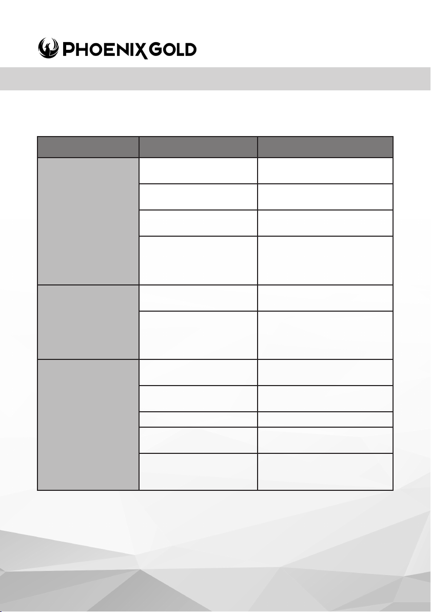
AMPLIFIER TROUBLESHOOTING
PROBLEM POSSIBLE REASON SOLUTION
No 12V to power wire Check fuses and
No power to remote
Amplier not
switching ON
LED = OFF
(not ‘Red or Blue’)
Amplier not work-
ing, status LED = Red
No Sound
LED = Blue
No ground connection Check ground cable is
Speaker wires shorted Check that there are no
Gain control not set up Ensure you have set up the
wire
Blown Fuse Replace fuse with correct
amplier and vehicle / body
Amplier too hot Move amplier to vented
RCA Signal Check RCA connection to
Head unit Check head unit volume
Amplier Check all power, remote on
Speakers Check speakers are
connections to battery
Check remote turn on
connections to head unit
type and amperage
correctly connected to the
chassis
area. Turn head unit down
speaker wires shorted to
another wire or to the
vehicle chassis
head unit
amplier gain level control
and ground connections
correctly connected
Check speakers for shorts
© 2021 Phoenix Gold | A Brand of AAMP Global
www.phoenixgold-eu.com
Page 11
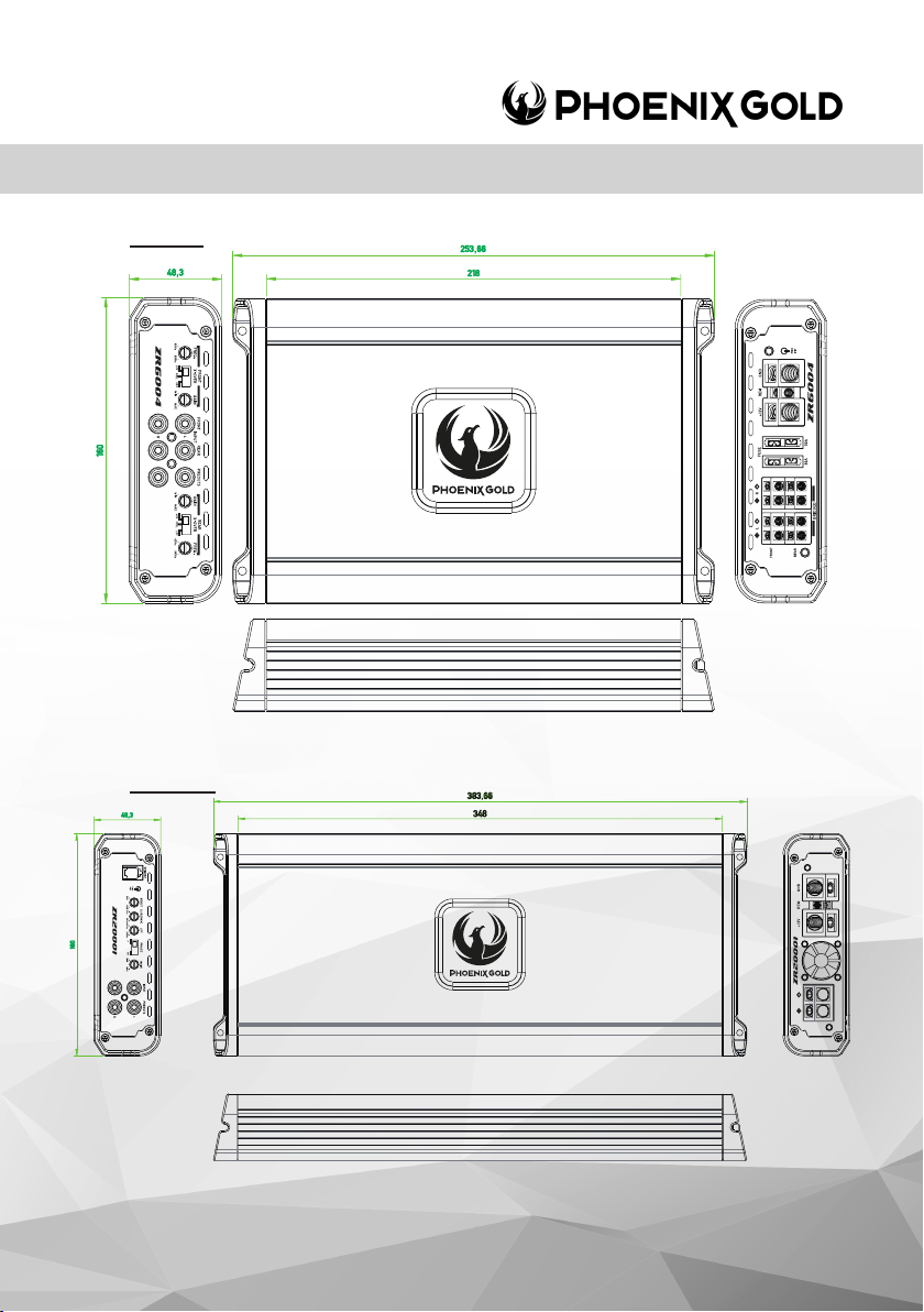
ZR6004
ZR20001
ZR6004 / ZR10001 / ZR20001 - ZR-Series Ampliers
© 2021 Phoenix Gold • www.phoenixgold-eu.com
Page 12
ZR6004 / ZR10001 / ZR20001 - ZR-Series Ampliers
ZR10001
Disclaimer
Always ensure the enclosure is securely attached, to avoid movement. PHOENIX GOLD accepts no responsibility for
damage or injury in relation to inappropriate securing of this product.
Phoenix Gold Product Warranty
LIMITED WARRANTY ON AMPLIFIERS:
Phoenix Gold warrants this product to be free of defects in materials and workmanship for a period of one (1) years
from the original date of purchase. This warranty is not transferable and applies only to the original purchaser from an
authorized Phoenix Gold dealer in the United States of America only. Should service be necessary under this warranty
for any reason due to manufacturing defect or malfunction, Phoenix Gold will (at its discretion) repair or replace
the defective product with new or re-manufactured product at no charge. Damage caused by the following is
not covered under warranty: accident, misuse, abuse, product modication or neglect, failure to follow installation
instructions, unauthorized repair attempts, misrepresentations by the seller. This warranty does not cover incidental or
consequential damages and does not cover the cost of removing or reinstalling the unit(s). Cosmetic damage due to
accident or normal wear and tear is not covered under warranty.
INTERNATIONAL WARRANTIES:
Products purchased outside the United States of America are covered only by that country’s Authorized Phoenix Gold
reseller and not by Phoenix Gold. Consumers needing service or warranty information for these products must contact
that country’s reseller for information.
© 2021 Phoenix Gold | A Brand of AAMP Global
www.phoenixgold-eu.com
REV .11/21
 Loading...