

Page 1
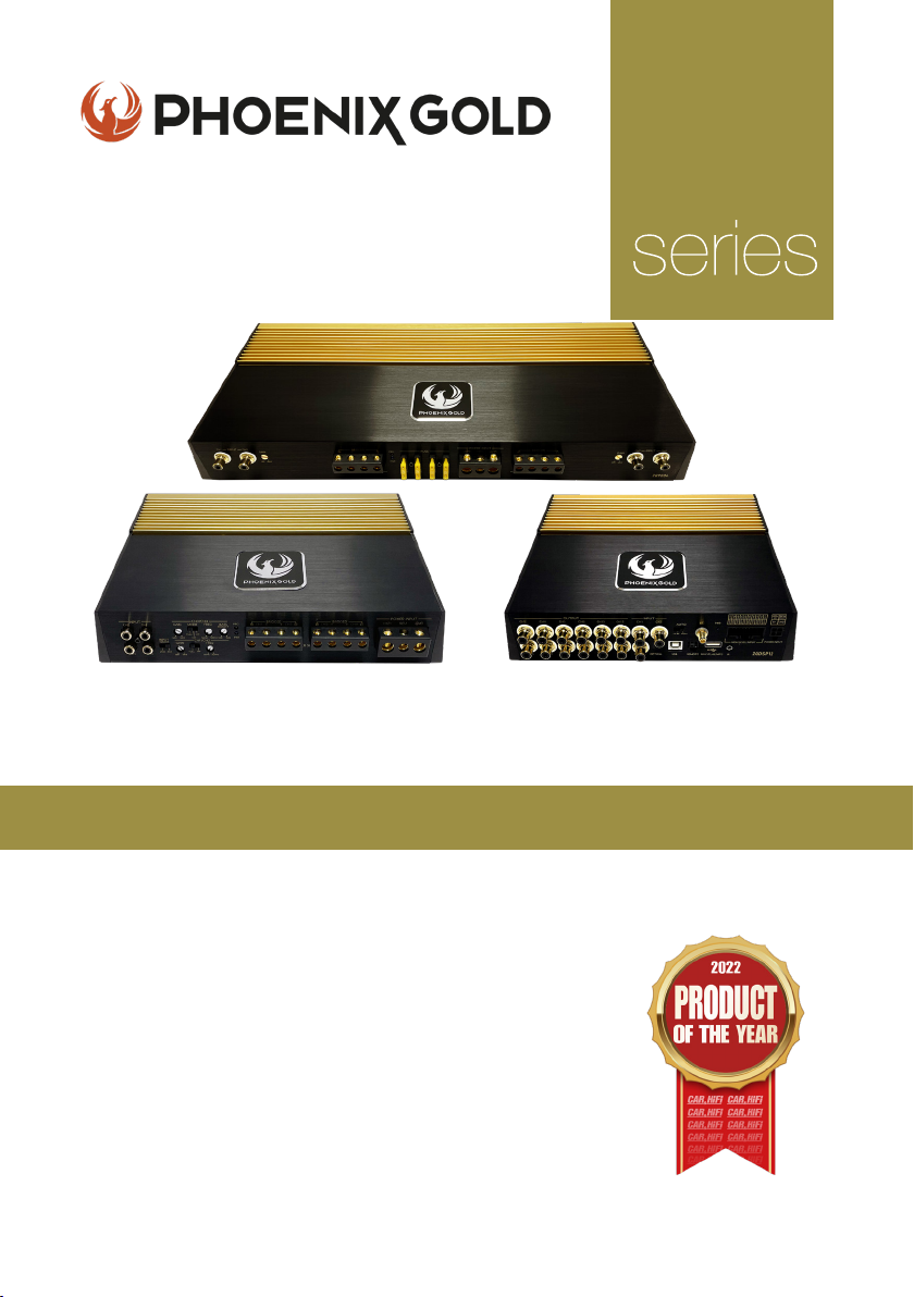
High-End Audiophile
ZQ
Ampliers and DSP’s
Model: ZQ9004 - ZQ5004 - ZQ15001 - ZQDSP12 - ZQA6.8
KEY FEATURES
- Two-Layer PCB with Immersion Gold Treatment
- High-end Polymer Gain Potentiometers
- Car & HiFi ‘Product of the Year 2022’ (ZQ9004)
- 24k Gold-Plated Terminals
- Nichicon & Wima Capacitors
- Toshiba & ON Transistors
- Shielded Transformer Cores
- S/N Ratio above 110dB
- Dual Power Supply
All specications subject to change without notice.
Page 2

ZQ Range Owners Manual
LIST OF CONTENTS
Ampliers
- Product Range Overview 3
- Precautions 3
- Installation 4
- Wiring Instructions 4
- Fuse Replacement 5
- Power Connection Leads 6
- Notes On Power Supply 6
- In Case of Faults 7
- Operation 8
- Interference & Noise 9
ZQ9004 10
- Specications 11
- Speakers Bridged/Connections 12
ZQ5004 13
- Specications 14
- Speakers Bridged/Connections 15
ZQ15001 16
- Specications 17
- Speakers Bridged/Connections 17
DSP’s
- Operation 18
- Troubleshooting 18
ZQA6.8 19
- Audio Signal Process 20
- Specications 21
- Connections 21
ZQDSP12 22
- Audio Signal Process 23
- Specications 24
- Connections 24
INTRODUCTION
Thank you for purchasing this extraordinary High-End amplier.
We have spent a lot of hours designing, listening and improving this amplier.
We hope you will enjoy this unique creation as much as we have loved making it! ENJOY!
Note: Some of these ampliers are pure class A/B amplier so they will get hot!
© 2021 Phoenix Gold • www.phoenixgold-eu.com
2
Page 3

ZQ Range Owners Manual
ZQ9004 / ZQ5004 / ZQ15001 - HIGH END AMPLIFIERS
PRODUCT RANGE OVERVIEW
The ZQ Range is designed in the EU by one of Phoenix Golds top amplier master
engineers, with over twenty years development experience in high end amplication.
In making this high-end range of ampliers/DSP’s, we insisted on using the best possible
components such as transistors from ON Semiconductor, EPCOS magnetic core
transformers, ELNA capacitors, Rubycon capacitors, Wima capacitors and Nichicon
capacitors and many other well-known high-quality components from around the world.
This top of the range audio set up has been developed as a highly exclusive and
valuable specialist audio electronics product. Phoenix Gold are constantly endeavouring
to meet the growing demands of audio enthusiasts around the world to let them feel the
ultimate sound experience. Passive components such as capacitors for example, may
not be at the centre of attention when compared to active components, but they still
form an indispensable part of the overall result. This is the key in making a really unique
amplier with fantastic performance.
We wish our Phoenix Gold clients the upmost enjoyment in listening to this amazing
creation. This product is the essence of Phoenix Golds brand values including some of the
original features that made us famous in the beginning like a gold plated circuit board
that are not only for show…. but because every little detail will affect the sound just like
the founders of Phoenix Gold knew.
PRECAUTIONS
u This unit is designed for negative ground 12V DC operation only.
u Avoid installing the amplier where:
- It would be subject to high temperature, such as from direct sunlight
or hot air from the heater
- It would be exposed to rain or moisture.
- It would be subject to dust or dirt.
u If your car is parked in direct sunlight and there is a considerable rise in
temperature inside the car, allow the amplier to cool off before operation.
u When installing the unit horizontally, be sure not to cover the heatsink ns
with the oor carpet.
u If this unit is placed too close to the car radio, an interference may occur.
In this case, separate the amplier from the car radio.
u This power amplier employs a protection circuit to protect the transistors
and speakers if the amplier malfunctions. Do not attempt to test the
protection circuits by covering the heatsink or connecting improper loads.
Do not use the amplier with a weak auto battery as its optimum
performance depends on a normal battery supply voltage.
u For safety reasons, keep the volume of your car audio system moderate so
that you can still hear normal trafc sounds outside your car.
© 2021 Phoenix Gold • www.phoenixgold-eu.com
3
Page 4

ZQ Range Owners Manual
ZQ9004 / ZQ5004 / ZQ15001 - HIGH END AMPLIFIERS
INSTALLATION
u First, ensure the mounting location is free of dirt and dust and that there is enough
ventilation in order to achieve optimum performance and avoid overheating when
the amplier is in use.
u Keep the wire connections as short as possible with sufcient length in order to
minimise any power losses and provide a higher audio output of the system.
u Where possible route all power and speaker wiring through any existing wire channels
within the vehicle in order to ensure wiring does not pass through sharp edged metal.
u Make sure all cables are away from any ignition cables or modules in the boot and
under the key dashboard components in order to avoid any interference.
u Add a fuse to the (+) power cable in a distance of not more than 30cm from the
positive battery pole.
u Ensure the power cable is as short as possible.
WIRING INSTRUCTIONS
POWER CONNECTION
The battery terminal (+12V) must be connected directly to the positive terminal of
the vehicle battery to provide an adequate voltage source and minimize noise.
Connecting the battery terminal lead to any other point (such as the fuse block) will
reduce the power output and may cause noise and distortion. Use only #8 gauge or
thicker (smaller gauge #) wire for this lead and connect it to the terminal of the
battery after all other wiring is completed.
GROUND CONNECTION
The ground terminal (GND) connection is critical to the correct operation of the amplier.
Use a wire of the same gauge as the power connection (#8 or thicker) and connect
it between the ground terminal (GND) of the amplier and a metal part of the vehicle
close to the mounting location. This wire should be as short as possible and any paint or
rust at the grounding point should be scraped away to provide a clean metal surface to
which the end of the ground wire can be screwed or bolted.
SPEAKER CONNECTIONS
Depending on the type and number of speakers used with the amplier, wired them to
the speaker terminals as per the appropriate wiring diagram.
For most applications 18 gauge wire should be used for the speaker leads but in no case
thinner than 20 gauge. For leads in excess of 10 feet 16 gauge is recommended.
When wiring the speakers, pay careful attention to the polarity of the terminals on the
speakers and make sure they correspond to the polarity of the corresponding terminals
on the amplier. Do not ground any speaker leads to the chassis of the vehicle.
© 2021 Phoenix Gold • www.phoenixgold-eu.com
4
Page 5

ZQ Range Owners Manual
ZQ9004 / ZQ5004 / ZQ15001 - HIGH END AMPLIFIERS
REMOTE TURN-ON CONNECTION
The amplier is turned on by applying +12V to the remote turn-on terminal (REM). The wire
leading to this terminal should be connected to the ‘Remote Out +12V’ lead from the car
stereo which will provide the +12V only when the car stereo is turned on. If the car stereo
does not provide an ‘Remote Out +12V’ lead, the remote turn-on lead may be wired to
an “Accessory“ or “Radio“ terminal in the car’s fuse block. This will turn the amplier on
and off with the ignition key, regardless of whether the car stereo is on or off. The remote
turn-on lead does not carry large currents, so a #20 gauge wire may be used for this
application.
FUSE
The amplier is equipped with a plug-in auto fuse which helps protect the amplier
against faulty conditions. Do not use a fuse with a higher value and never bridge the fuse,
as this may lead to the warranty of the amplier being denied/void.
FUSE REPLACEMENT
If the fuse blows, check the power connection and replace the fuse. If the fuse
blows again after replacement, there may be an internal malfunction. In this
case, consult your dealer.
WARNING:
Use the specied fuse. Use of a higher fuse may cause serious damage.
PROTECTION CIRCUIT:
This amplier is provided with a protection circuit which operates in the following cases when:
u The unit is overheated.*
u The speaker terminals are short-circuited.
*THERMAL PROTECTION:
As these ampliers are Class A/B, they can tend to get hot when being used for
long periods of time.
In the case that the amplier goes into ‘thermal protection’, please provide
better airow around the unit.
© 2021 Phoenix Gold • www.phoenixgold-eu.com
5
Page 6
ZQ Range Owners Manual
POWER
ZQ9004 / ZQ5004 / ZQ15001 - HIGH END AMPLIFIERS
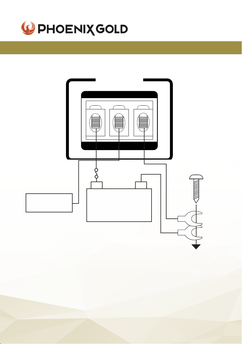
POWER CONNECTION LEADS
REMOTE OUT
HEAD UNIT
12V+
12V
POWER
+
REM GND
INPUT
FUSE
-
BATTERY
DC 12V
to a metal part
of the car
NOTES ON THE POWER SUPPLY
u Connect the +12V power input lead only after all other leads have
been connected.
u Be sure to connect the ground wire of the unit securely to a metal part of
the vehicle.
u A loose connection may cause a malfunction of the amplier.
u Place the fuse in the power supply lead as close as possible to the car
battery.
© 2021 Phoenix Gold • www.phoenixgold-eu.com
6
Page 7

ZQ Range Owners Manual
ZQ9004 / ZQ5004 / ZQ15001 - HIGH END AMPLIFIERS
NOTES ON THE POWER SUPPLY
u The unit is turned on by applying +12 Volts to the REM (Remote In). This
terminal does not draw heavy current like the main Power Terminals so a
thinner connecting wire is acceptable. Standard 18 GAUGE is ne and the
standard colour is blue. If the radio is equipped with a Power Antenna
control wire, it can drive this terminal. If the Power Antenna wire is already
in use, you can still splice into it. With this method, the unit will turn on
automatically with the radio. Use the power supply lead with a fuse
attached whose value is the same as the original fuse inside the amplier.
u During a full power operation, maximum current will run through the system,
therefore, make sure that the leads to be connected to the +12V and GND
terminals of the unit respectively must be larger than 10 Gauge (AWG.10).
IN CASE OF FAULTS
NO FUNCTION
The connection cable is not connected correctly (terminal BATT/GND /REM). Ensure that all
connections, mechanical contacts, and wire jackets have been removed. The fuse might be
defective - pay attention to the correct value of a new fuse!
NO SOUND
Speaker cable or RCA plugs are not connected correctly.
NO SOUND / RED LED PROTECTION SHINES:
The plus and minus wires of the speaker cable shorted, thus creating a short circuit. If you use a 2 Ohm
speaker in stereo mode, turn the gain control to “min” until the operation is free of trouble.
POOR SOUND QUALITY (DISTORTIONS)
The speakers are overloaded, therefore turn down the volume level and check the volume control
positions.
NO STEREO AND A WEAK BASS
Left and right speaker cables (+) and (-) are out of phase.
© 2021 Phoenix Gold • www.phoenixgold-eu.com
7
Page 8

ZQ Range Owners Manual
ZQ9004 / ZQ5004 / ZQ15001 - HIGH END AMPLIFIERS
OPERATION
After the amplier has been installed and all connections have been made
carefully and securely, turn the radio on so that the amplier is switched on
automatically. After a short power-on period, the amplier reaches its full
performance.
Now turn up the volume slowly using the volume control of the radio.
If there is no sound or only a distorted replay, switch off the radio immediately,
the amplier will also switch off automatically - and check if all connections
have been made correctly.
POWER = LED POWER INDICATOR
After the correct connection order of the three power terminals, the LED
indicator shines green and goes out when is off.
PROTECT = LED PROTECTION INDICATOR
This unit is equipped with an overload protection function. Immediately upon
overloading (due to short circuit or much increased temperature) the overload
protection is activated, and the red LED indicator is shining. This means the
amplier is protected.
LEVEL CONTROL
The input level control allows the system to work well within a wide range of
output levels. Choose the adjustment in the way that you achieve a sound
without any distortion.
As a guideline the following procedure is recommended:
If you use several ampliers, the adjustment has to made for each set
separately. Tune the volume control of your car to 2/3rds of the maximum
volume. Now turn the gain control of the amplier from ‘MIN’ to ‘MAX’
direction until you can hear distortions. Then turn the level control a little
back to ‘MIN’. The gain control adjustment is nished.
ATTENTION - If you use 2 Ohm speakers in stereo mode, turn the gain control to
‘MIN’ direction, until the operation is free of trouble.
© 2021 Phoenix Gold • www.phoenixgold-eu.com
8
Page 9

ZQ Range Owners Manual
ZQ9004 / ZQ5004 / ZQ15001 - HIGH END AMPLIFIERS
INTERFERENCE & NOISE
All cables are sources of interference and noise. The power cable and RCA
audio cable are very prone to interference; the remote cables are less prone.
The interference can be caused by the generator (piping), ignition (cracking)
or other car electronic parts. Most of these problems can be eliminated by
correct and careful cabling. In doing so, these are the following guidelines:
u Use only an RCA audio cable for the wiring between the amplier and RCA
output of the radio.
u Lay the signal, speaker and power cables separately with enough
distance from one another and also from each other car cable.
If not possible, you can lay the circuit and ground cable together with the
serial cables. Audio and speaker cable should be as far away from these as
possible. The REM cable to the automatic antenna output of the radio can
be laid together with the signal cables.
u Avoid ground loops by laying the ground wiring of all components to a
centre point in a star-like way. You can nd the best central point in
measuring the voltage directly at the battery. Now compare this voltage
value with the chosen ground point and the (+) terminal of the amplier.
If the measured voltage is only less different, you’ve found the correct
central. Otherwise, you have to look for another point. You should measure
with the ignition being switched on and additionally switched on other
electronics (rear window heating and light). If there are pickups from
external electrical sources into the speaker cables, divide the core leads
and twist them together.
u If there are noises from the car electronics, add a noise suppression choke
to the power wiring.
u If there are humming noises, use thicker ground cables or add further
ground cables to the chassis.
u To reduce contact resistance and bad/loose contacts, please tin the
cable ends or use multi-core cable ends, spade terminals or others.
Note - plated spade terminals are free of corrosion and have the lowest
contact resistance.
u Should any of these measures have no success, the use of a ground loop
isolator may solve the problem. If the problem persists, contact a certied
car audio installer.
© 2021 Phoenix Gold • www.phoenixgold-eu.com
9
Page 10
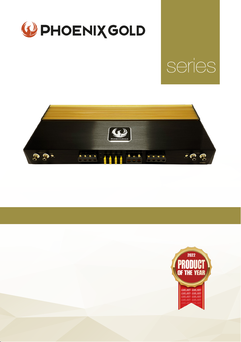
High-End 4 Channel Amplier
ZQ
KEY FEATURES
- Two-Layer PCB with Immersion Gold Treatment
- High-end Polymer Gain Potentiometers
- Car & HiFi ‘Product of the Year 2022’
- 24k Gold-Plated Terminals
- Nichicon & Wima Capacitors
- Toshiba & ON Transistors
- Shielded Transformer Cores
- S/N Ratio above 110dB
- Dual Power Supply
Model: ZQ9004
All specications subject to change without notice.
Page 11

ZQ Range Owners Manual
ZQ9004 - 4 CHANNEL AMPLIFIER
SPECIFICATIONS
Supply Voltage
Power Output @ 4 ohm
Power Output @ 2 ohm
Power Output @ 4 ohm
Frequency Response
Channel Separation
Signal to Noise Ratio
Input Impedance
Input Sensitivity
T.H.D
11-15V DC
150W x 4
230W x 4
380W x 2 (Bridged)
10Hz - 55KHz (-3dB)
60dB
+110dB
22K Ohm
400mV - 5V
<0.05%
u 4 Channel Power Amplier
u Low Level Input
u Gain Control
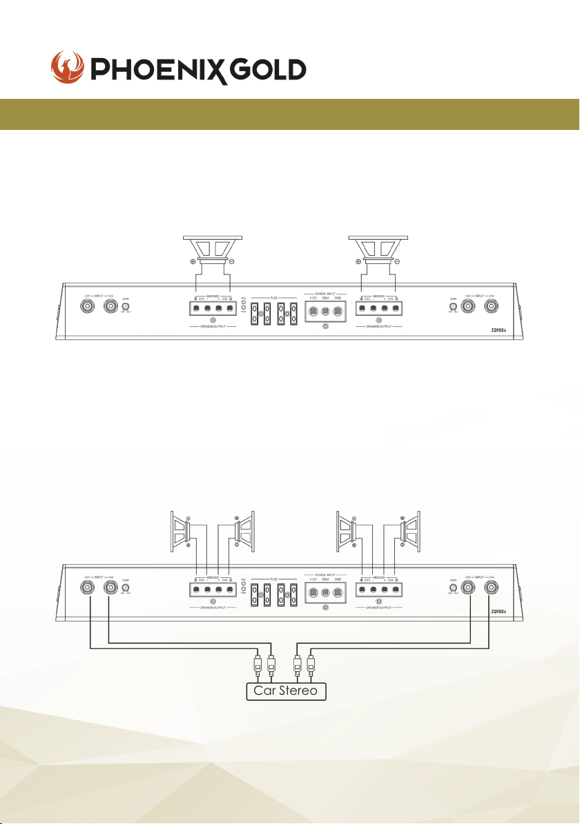
Note that the two speakers & four speakers have been connected to the four terminal
following the (+) and (-) graphic. Your speaker terminal may be marked (+) and (-) or
there may be red dot by one terminal which means the same as (+). Connecting the
speakers in this manner assures that the two speaker cones will move in and out together
according to the original recording. If one of the two speakers is reversed, stereo imaging
and bass response will be degraded.
u LED Power & Protection Indicator
u Mosfet Power Supply
u Thermal Protection
© 2021 Phoenix Gold • www.phoenixgold-eu.com
11
Page 12
ZQ9004 - 4 CHANNEL AMPLIFIER
SPEAKERS BRIDGED
ZQ Range Owners Manual
Mono
Speaker
Min: 4 Ohm
SPEAKER CONNECTIONS
CH1 Speaker
Min: 2 Ohm
CH2 Speaker
Min: 2 Ohm
Speaker
Min: 4 Ohm
CH3 Speaker
Min: 2 Ohm
Mono
CH4 Speaker
Min: 2 Ohm
Car Stereo
© 2021 Phoenix Gold • www.phoenixgold-eu.com
12
Page 13
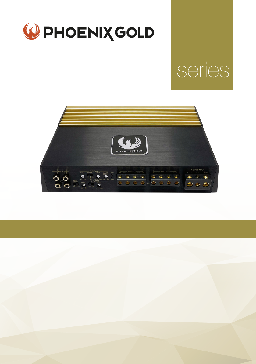
High-End 4 Channel Amplier
ZQ
KEY FEATURES
- Two-Layer PCB with Immersion Gold Treatment
- High-end Polymer Gain Potentiometers
- Dual Colour Heatsink for Heat Transfer Optimisation
- Imported High-Quality Transformer Core
- 24k Gold-Plated Terminals
- Nichicon & Siemens Capacitors
- Toshiba & ON Transistors
- S/N Ratio above 110dB
- Dual Power Supply
Model: ZQ5004
All specications subject to change without notice.
Page 14

ZQ Range Owners Manual
ZQ5004 - 4 CHANNEL AMPLIFIER
SPECIFICATIONS
Supply Voltage
Power Output @ 4 ohm
Power Output @ 2 ohm
Power Output @ 4 ohm
Frequency Response
HP/LP Frequency
Bass Boost
Channel Separation
Signal to Noise Ratio
Input Impedance
Input Sensitivity
T.H.D
u 4 Channel Power Amplier
u Bass Boost Control
u Low Level Input
u Crossover Control
u HP/LP Filter Control
Note that the two speakers & four speakers have been connected to the four terminal
following the (+) and (-) graphic. Your speaker terminal may be marked (+) and (-) or
there may be red dot by one terminal which means the same as (+). Connecting the
speakers in this manner assures that the two speaker cones will move in and out together
according to the original recording. If one of the two speakers is reversed, stereo imaging
and bass response will be degraded.
11-15V DC
95W x 4
150W x 4
260W x 2 (Bridged)
10Hz - 55KHz (-3dB)
50Hz - 500Hz
0 - 18dB
60dB
+100dB
22K Ohm
250mV - 5V
<0.05%
u LED Power & Protection Indicator
u Mosfet Power Supply
u Thermal Protection
u Short Circuit Protection
u Gain Control
STEREO MODE
*
Car Stereo
* Input mode allows for both ‘2 channel’ and ‘4 channel’ RCA inputs. When ‘2 channel’
selected, CH1 & CH2 will also provide signals for CH3 & CH4.
© 2021 Phoenix Gold • www.phoenixgold-eu.com
14
Page 15

ZQ Range Owners Manual
ZQ5004 - 4 CHANNEL AMPLIFIER
SPEAKERS BRIDGED
SPEAKER CONNECTIONS
CH2 Speaker
Min: 2 Ohm
CH1 Speaker
Min: 2 Ohm
Mono
Speaker
Min: 4 Ohm
Mono
Speaker
Min: 4 Ohm
CH3 Speaker
Min: 2 Ohm
CH4 Speaker
Min: 2 Ohm
© 2021 Phoenix Gold • www.phoenixgold-eu.com
15
Page 16
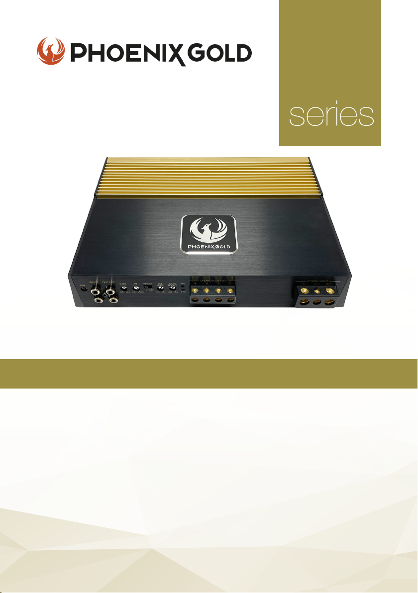
High-End 1 Channel Amplier
ZQ
KEY FEATURES
- Two-Layer PCB with Immersion Gold Treatment
- High-end Polymer Gain Potentiometers
- Dual Colour Heatsink for Heat Transfer Optimisation
- 24k Gold-Plated Terminals
- Siemens Capacitors
- IR Transistors
- High-Quality Transformer Cores
- S/N Ratio above 110dB
- Dual Power Supply
Model: ZQ15001
All specications subject to change without notice.
Page 17
ZQ Range Owners Manual
ZQ15001 - 1 CHANNEL AMPLIFIER
SPECIFICATIONS
Supply Voltage
Power Output @ 4 ohm
Power Output @ 2 ohm
Power Output @ 1 ohm
Frequency Response
Low Pass Frequency
Subsonic Frequency
Phase Shift Control
Bass Boost
Signal to Noise Ratio
Input Impedance
Input Sensitivity
T.H.D
u 1 Channel Power Amplier
u Bass Boost Control
u Low Level Input
u Low Pass Filter Control
u Gain Control
11-15V DC
500W x 1
850W x 1
1200W x 1
5Hz - 250Hz (-3dB)
40Hz - 250Hz
5Hz - 50Hz
0 - 180°
0 - 12dB
+80dB
20K Ohm
150mV - 5V
<0.05%
u LED Power & Protection Indicator
u Mosfet Power Supply
u Short Circuit & Thermal Protection
u Phase Control
u Remote Control Included
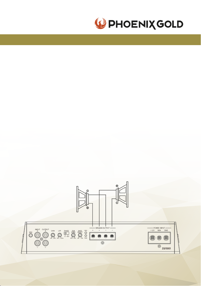
SPEAKER CONNECTIONS
Mono
Speaker
Min: 2 Ohm
Mono
Speaker
Min: 2 Ohm
© 2021 Phoenix Gold • www.phoenixgold-eu.com
17
Page 18

ZQ Range Owners Manual
ZQA6.8 / ZQDSP12 - HIGH END DSP
OPERATION
When the switch is toggled to DC, the DSP is automatically switched for high
level inputs. When switched to REM, the output (REM OUT) of the DSP must be
connected to the input connector (REM IN) of the amplier to work. After a few
operations turning the DSP on and off, the DSP has direct current and the switch
must be turned to REM IN to control the switch gear.
The product has one REM OUT option and can be connected with the REM
input of another amplier to control the DSP with an externally powered
amplier. If used in this way, please ensure the RCA low level output connector
is connected to the external amplier system. Be sure to use the REM OUT
connector of this machine to control the REM Input of the external amplier,
otherwise, it may cause overpowering and result in a re.
COMMON TROUBLESHOOTING
NO POWER
The connection cable is not connected correctly (terminal BATT/GND /REM). Ensure that all
connections, mechanical contacts, and wire jackets have been removed. The fuse might be
defective - pay attention to the correct value of a new fuse!
NO SOUND
Speaker cable or RCA plugs are not connected correctly. Check if ‘Mute’ setting is applied. Check if
input channel is selected correctly.
© 2021 Phoenix Gold • www.phoenixgold-eu.com
18
Page 19
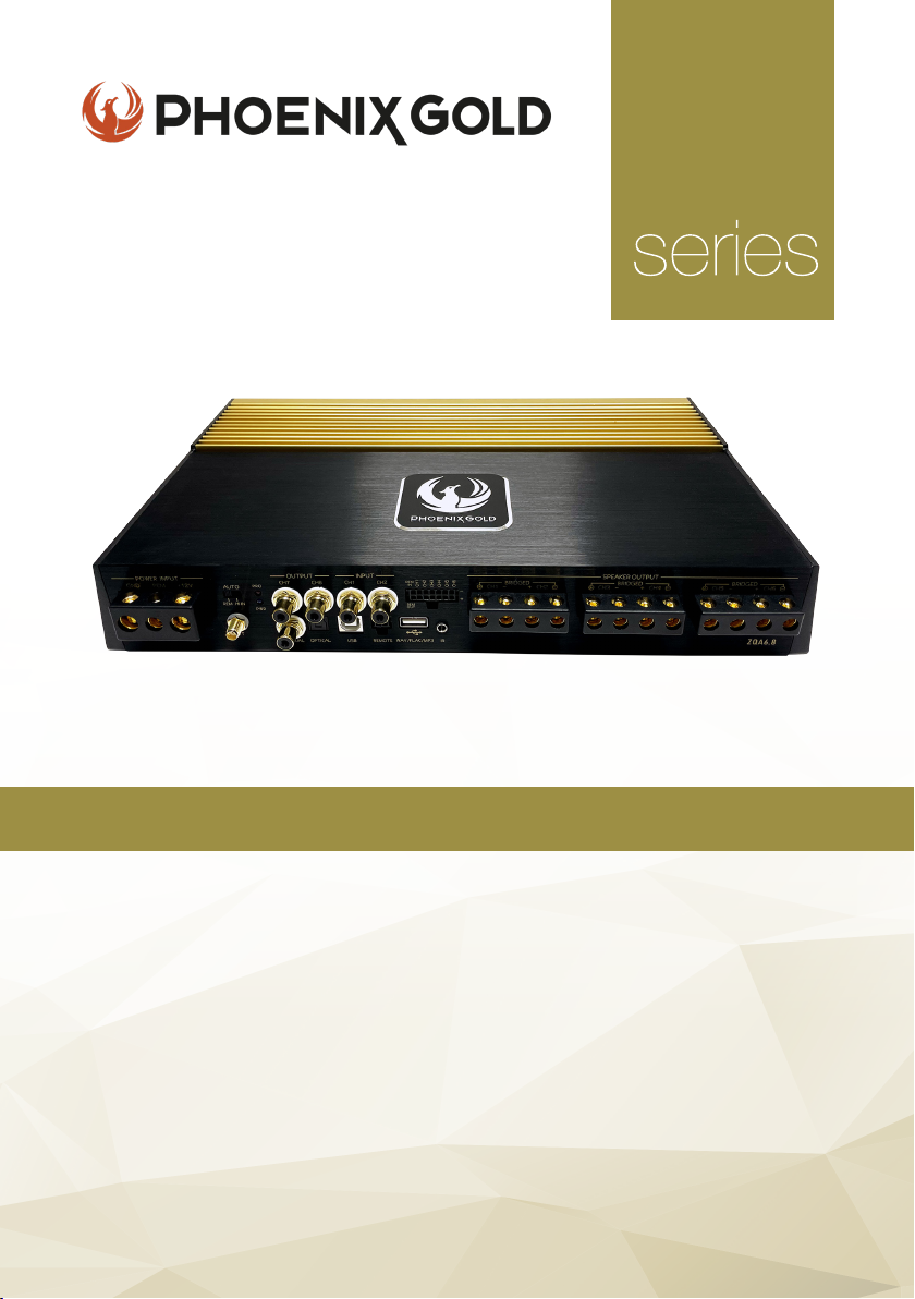
High-End 6 Channel Amplier
ZQ
with 8 Channel DSP
KEY FEATURES
- Two-Layer PCB with Immersion Gold Treatment
- 6 Channel Amplier
- Built in 8 Channel Digital Signal Processor
- 24k Gold-Plated Terminals
- Nichicon & Siemens Capacitors
- Toshiba & ON Transistors
- High-Quality Transformer Cores
- USB playback & Bluetooth built-in
- Windows software compatible
Model: ZQA6.8
All specications subject to change without notice.
Page 20
ZQ Range Owners Manual
ZQA6.8 - 8 CHANNEL DSP
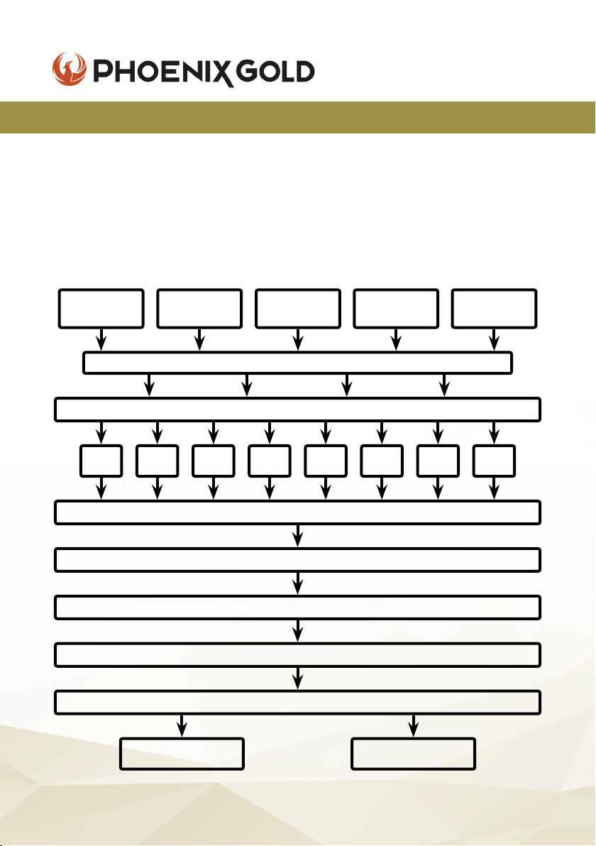
AUDIO SIGNAL PROCESS
This device uses 96kHz high sampling rate audio extraction mode. 32-bit
resolution industry good Delta-Sigma A/D and D/A conversion, the core
processor is the high resolution, 48-bit double precision oating point and
160MHz digital signal processor (DSP). Digital audio processing, including
gain control, signal phase, delay and frequency device (low shear and high
cut lter, the types of specialized division include: link/bessel/butterworth,
eightslope 12dB 18dB 24dB 30dB 36dB 42dB 48dB 0dB optional) etc.
Two Low
Level Input
CH1 CH2 CH3 CH4 CH5 CH6 CH7 CH8
Six High
Level Input
31 Segment Equalizer per Output Channel
Phase / Time Delay / Mute
Bluetooth
Input
Main Input Selection
Output/Input Adapter
Output Volume
Filter / Slope Choice
Output Volume
Optical /
Coaxial Input
USB
Player
95W x 6
Amp Output
© 2021 Phoenix Gold • www.phoenixgold-eu.com
CH7 - CH8
Low Level Output
20
Page 21
ZQ Range Owners Manual
ZQA6.8 - 8 CHANNEL DSP
SPECIFICATIONS
Supply Voltage
Power Output @ 4 ohm
Power Output @ 2 ohm
Power Output @ 4 ohm
Frequency Response
Signal to Noise Ratio
Input Sensitivity
T.H.D
DSP FUNCTIONALITY
Input Signal Type
Output Signal Type
Output Signal Gain
Equalizer Bands per CH
Equalizer type
Equalizer Freq. range
Equalizer Gain
Output Signal Crossover
Crosser type
Filter Crossover
Filter Slope Setting
Output Phase
Time Delay
6-CH High, 2-CH Low, Bluetooth, Optical/Coaxial
Free denable output sound position & speaker type
Mute, -59dB to 0dB
31 band equalizer engine
GEQ/PEQ
20Hz - 20kHz
-15dB to +15dB
Each output with 2 rank’s high/low pass lter
Butterworth, Linkwitz-Riley, Bessel
20Hz - 20kHz
12,18,24,30,36,42,48dB per Octave
0 - 180°
0.000-12.479ms - 0.00-424.286cm
11-15V DC
95W x 6
150W x 6
95W x 4 + 280W x 1
10Hz - 22kHz (-3dB)
+100dB
300mV - 2.5V
<0.1%
Scan me to download
ZQ DSP PC Software
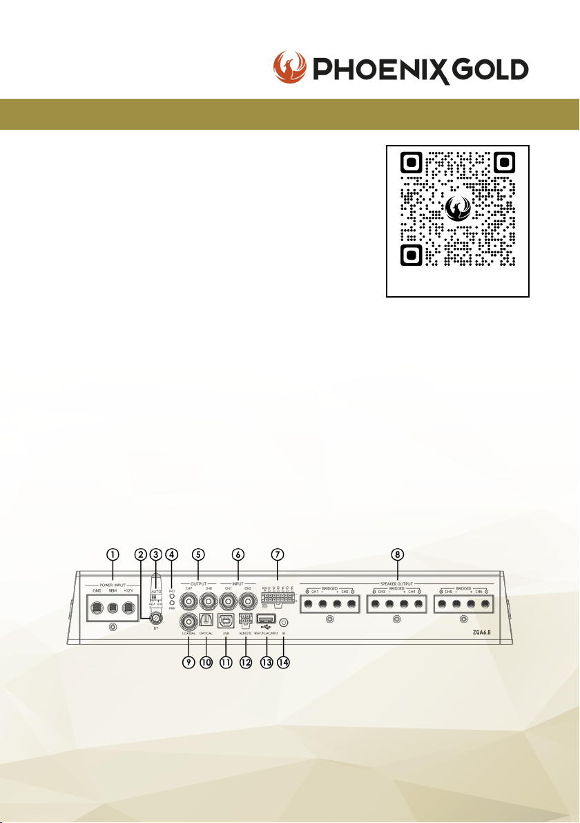
CONNECTIONS
1. Power Input 6. Low Level RCA Input 10. Optical Input
2. Bluetooth Antenna 7. Hi-Level Input & 11.USB 2.0 Input (for PC)
3. REM 12V or AutoStart Remote In/Out 12. Remote Control*
4. Power/Protection LED 8. Speaker Output 13. USB Port (for media)
5. Low Level RCA Output 9. Coaxial Input 14. IR Input*
© 2021 Phoenix Gold • www.phoenixgold-eu.com
21
*optional inputs
Page 22
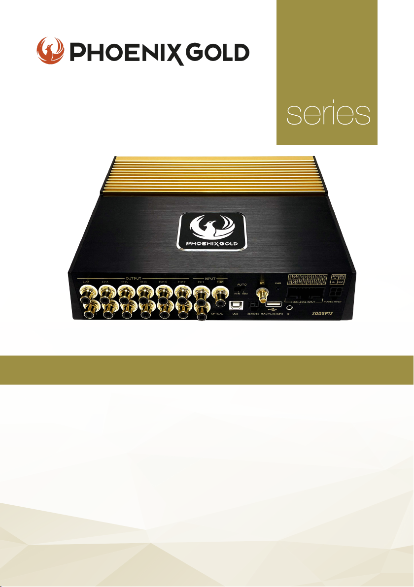
High-End 12 Channel DSP
ZQ
KEY FEATURES
- Two-Layer PCB with Immersion Gold Treatment
- Digital Signal Processor with Analog & Digital Inputs
- 24k Gold-Plated Terminals
- ELNA Capacitors
- ADI1452 Chip Transistors
- Shielded Transformer Cores
- USB playback & Bluetooth built-in
- Windows software compatible
- Dual Power Supply
Model: ZQDSP12
All specications subject to change without notice.
Page 23
ZQ Range Owners Manual
ZQDSP12 - 12 CHANNEL DSP
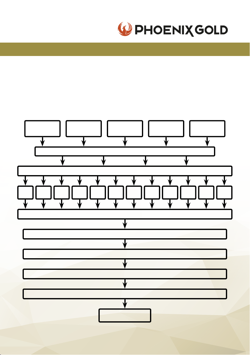
AUDIO SIGNAL PROCESS
This device uses 96kHz high sampling rate audio extraction mode. 32-bit
resolution industry good Delta-Sigma A/D and D/A conversion, the core
processor is the high resolution, 48-bit double precision oating point and
160MHz digital signal processor (DSP). Digital audio processing, including
gain control, signal phase, delay and frequency device (low shear and high
cut lter, the types of specialized division include: link/bessel/butterworth,
eightslope 12dB 18dB 24dB 30dB 36dB 42dB 48dB 0dB optional) etc.
Two Low
Level Input
CH1 CH2 CH3 CH4 CH5 CH6 CH7 CH8 CH9 CH10
Independent High-Low Pass Filter per Output (3 lters can be selected)
Ten High
Level Input
31 Segment Equalizer per Output Channel
Phase / Time Delay / Mute
Bluetooth
Input
Main Input Selection
Output/Input Adapter
Output Volume
Output Volume
Optical /
Coaxial Input
USB
Player
CH11 CH12
CH1 - CH12
Low Level Output
© 2021 Phoenix Gold • www.phoenixgold-eu.com
23
Page 24
ZQDSP12 - 12 CHANNEL DSP
SPECIFICATIONS
Supply Voltage
Frequency Response
Input Sensitivity
Signal to Noise Ratio
Input Sensitivity
T.H.D
DSP FUNCTIONALITY
Input Signal Type
Output Signal Type
Output Signal Gain
Equalizer Bands per CH
Equalizer type
Equalizer Freq. range
Equalizer Gain
Output Signal Crossover
Crosser type
Filter Crossover
Filter Slope Setting
Output Phase
Time Delay
ZQ Range Owners Manual
11-15V DC
10Hz - 22kHz (-3dB)
50dB
+100dB
1V - 2.5V
<0.1%
Scan me to download
ZQ DSP PC Software
10-CH High, 2-CH Low, Bluetooth, Optical/Coaxial
Free denable output sound position & speaker type
Mute, -59dB to 0dB
31 band equalizer engine
GEQ/PEQ
20Hz - 20kHz
-15dB to +15dB
Each output with 2 rank’s high/low pass lter
Butterworth, Linkwitz-Riley, Bessel
20Hz - 20kHz
12,18,24,30,36,42,48dB per Octave
0 - 180°
0.000-12.479ms - 0.00-424.286cm
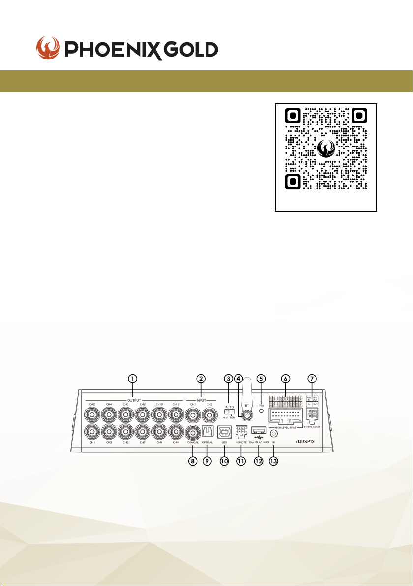
CONNECTIONS
1. CH1-12 Low Level Outputs 6. Hi-Level Input 11. Remote Control*
2. 2x Low Level Inputs 7. Power, Remote In/Out 12. USB Port (for media)
3. Hi In/REM Convertor 8. Coaxial Input 13. IR Input*
4. Bluetooth Antenna 9. Optical Input
5. Power LED 10. USB 2.0 Input (for PC)
© 2021 Phoenix Gold • www.phoenixgold-eu.com
24
*optional inputs
Page 25

ZQ Range Owners Manual
NOTES
© 2021 Phoenix Gold • www.phoenixgold-eu.com
25
Page 26

Scan me to download
ZQ DSP PC Software
A Brand of AAMP Global.
phoenixgold-eu.com
© Copyright 2021
Phoenix Gold Product Warranty
LIMITED WARRANTY ON AMPLIFIERS
Phoenix Gold warrants this product to be free of defects in materials and workmanship for a period
of one (1) years from the original date of purchase. This warranty is not transferable and applies only
to the original purchaser from an authorized Phoenix Gold dealer in the United States of America
only. Should service be necessary under this warranty for any reason due to manufacturing defect
or malfunction, Phoenix Gold will (at its discretion) repair or replace the defective product with new
or re-manufactured product at no charge. Damage caused by the following is not covered under
warranty: accident, misuse, abuse, product modication or neglect, failure to follow installation
instructions, unauthorized repair attempts, misrepresentations by the seller. This warranty does not
cover incidental or consequential damages and does not cover the cost of removing or reinstalling
the unit(s). Cosmetic damage due to accident or normal wear and tear is not covered under
warranty.
INTERNATIONAL WARRANTIES:
Products purchased outside the United States of America are covered only by that country’s
Authorized Phoenix Gold reseller and not by Phoenix Gold. Consumers needing service or warranty
information for these products must contact that country’s reseller for information.
REV 1.0522
 Loading...