

Page 1
Page 2

Page 3

TAB LE OF CON TENTS
Introduction and Overview . . . . . . . . . . . . . . . . . . . . . . . . . .2
Features and Specifications . . . . . . . . . . . . . . . . . . . . . . . . .3
H A R D WA R E
Operational Details . . . . . . . . . . . . . . . . . . . . . . . . . . . . . .4
Ground Triggered Outputs . . . . . . . . . . . . . . . . . . . . . . . . . .5
S O F T WA R E
Volume Control . . . . . . . . . . . . . . . . . . . . . . . . . . . . . . . . .6
30 Band Equalizer . . . . . . . . . . . . . . . . . . . . . . . . . . . . . . .7
Changing the Q of a slider filter . . . . . . . . . . . . . . . . . . . . . .8
Digital Signal Processing . . . . . . . . . . . . . . . . . . . . . . . . . . .9
Time Delay Explanation . . . . . . . . . . . . . . . . . . . . . . . . . . .10
Software Toolbar Options . . . . . . . . . . . . . . . . . . . . . . . . . .11
Importing a PC RTAjr file . . . . . . . . . . . . . . . . . . . . . . . . . . .12
Troubleshooting . . . . . . . . . . . . . . . . . . . . . . . . . . . . . . . . .13
2
TID EQ INTR ODU CTIO N
Thank you for purchasing the Phoenix Gold TiDEQ Comp. By doing
so, you have demonstrated a desire to own the finest audio components available for your vehicle. At Phoenix Gold, we use state of
the art design, engineering and production methods to continually
improve the quality, reliability and performance of our products.
The TiDEQ Comp was designed for the demanding competitor or serious enthusiast. When properly installed by an Authorized Phoenix
Gold Mobile Electronics Retailer, this equipment will provide years of
enjoyment. For proper operation, please read this manual carefully
and keep it for future reference.
TIDE Q OVER VIEW OF OPER ATI ON
The TiDEQ Comp has 4 separate presets built into one unit. Each
preset contains a stereo 30 band 1/3 Octave equalizer. The four
separate 30 band equalizer presets are labeled RTA, SPL, SQ, or
USER. All four presets are stored in the TiDEQ comp at the same
time, this allows users to toggle through the 4 presets. Interfacing
the TiDEQ Comp with a Personal Computer gives the user several
more control functions: adjustable Q for all 30 bands, 3 more bands
of parametric equalization per channel, Time Delay for left and right
channels. All changes and equalization to the signal will be done on
the TiDEQ Comp software and then transmitted to the TiDEQ Comp.
The changes will only take affect in the vehicle when the information
is transmitted from the TiDEQ software to the TiDEQ Comp.
The TiDEQ software is optimized to run with nearly any speed of
Personal Computer such as a Pentium 90 or faster with Windows 98
or 2000.
Please note that the TiDEQ software CD-ROM includes a
comprehensive Help file and Adobe Acrobat version of this manual.
P H O E N I X G O L D I N T E R N AT I O N A L
Page 4

3
TiD EQ FEA TURES
• 24 bit 96kHz AD/DA Convertors for the ultimate sound fidelity
• 48 bit Internal Arithmetic Digital Signal Processing
• 30 bands of 1/3 Octave spaced equalization per channel per preset
• Variable Q for all 30 bands of equalization per channel per preset*
• 3 additional bands of parametric equalization per channel per preset*
• 4 presets: RTA, SPL, SQ, and USER
• 4 Ground Triggered Outputs for activating external relays
• 6 Sensor Inputs for monitoring other 12 volt components on the optional TiDEQ Comp Remote**
• High or Low Pass Filter selectable at 12 or 24dB per octave from 20Hz to 20kHz per channel*
• Digital Time Delay for each channel adjustable from 0 to .1 seconds*
• Delayed Remote Output for connecting multiple system components
• Built in Pink Noise Generator*
*(Additional features for use with TiDEQ Comp software only)
**(Additional features for use with TiDEQ Comp software and Remote Control only)
TIDEQ SPE CIFI CAT IONS
Frequency Response . . . . . . . . . . . . . . . . . . . . . . . . . . . . . . . .+/-1dB, 20Hz to 20kHz
S/N Ratio (A-weighted) . . . . . . . . . . . . . . . . . . . . . . . . . . . . .>115dB
Total Harmonic Distortion . . . . . . . . . . . . . . . . . . . . . . . . . . . .0.07%
Input Impedance . . . . . . . . . . . . . . . . . . . . . . . . . . . . . . . . . .30k ohms
Output Impedance . . . . . . . . . . . . . . . . . . . . . . . . . . . . . . . . .37 ohms
Input Signal Range . . . . . . . . . . . . . . . . . . . . . . . . . . . . . . . .1 to 4 Vrms
Maximum Output Level . . . . . . . . . . . . . . . . . . . . . . . . . . . . . .4 Vrms
Slider Filter Q . . . . . . . . . . . . . . . . . . . . . . . . . . . . . . . . . . . .Variable from 1 to 17
Slider Filter Boost/Cut Range . . . . . . . . . . . . . . . . . . . . . . . . . .-18dB to +6dB
Slider Filter Center Frequency Spacing . . . . . . . . . . . . . . . . . . . .1/3 Octave
Power Supply Operating Range . . . . . . . . . . . . . . . . . . . . . . . . .10.5 Vdc to 15.5 Vdc
Typical DC Current Draw . . . . . . . . . . . . . . . . . . . . . . . . . . . . .1 amp
Dimensions, Chassis (inches) . . . . . . . . . . . . . . . . . . . . . . . . . .13.5 L x 10.00 W x 2.25 H
Dimensions, Overall (inches) . . . . . . . . . . . . . . . . . . . . . . . . . .14.0 L x 10.25 W x 2.25 H
* Due to continuous product development, features and specifications are subject to change without notice.
COMP UTE R MINIM UM RE QUIREMENTS
Pentium 90 or faster
32 megs of ram
30 Megs Free of Hard Drive Space
CD Rom Drive
Windows 98 or 2000 Software
Mouse/Keyboard
Unused Serial Port
Windows 98 and 2000 are registered trademarks of Microsoft Corporation
P H O E N I X G O L D I N T E R N A T I O N A L
Page 5
PRESET
PRESET
SELECT
SELECT
INPUT OUTPUT
INPUT OUTPUT
TRIGGER
L
L
OUTPUT
USER SQ RTA SPL
R
R
SENSOR INPUT
1 2 3 64 5
4
POWER
COMPUTERREMOTE DISPLAY
B+ B- R DR
I N P U T S
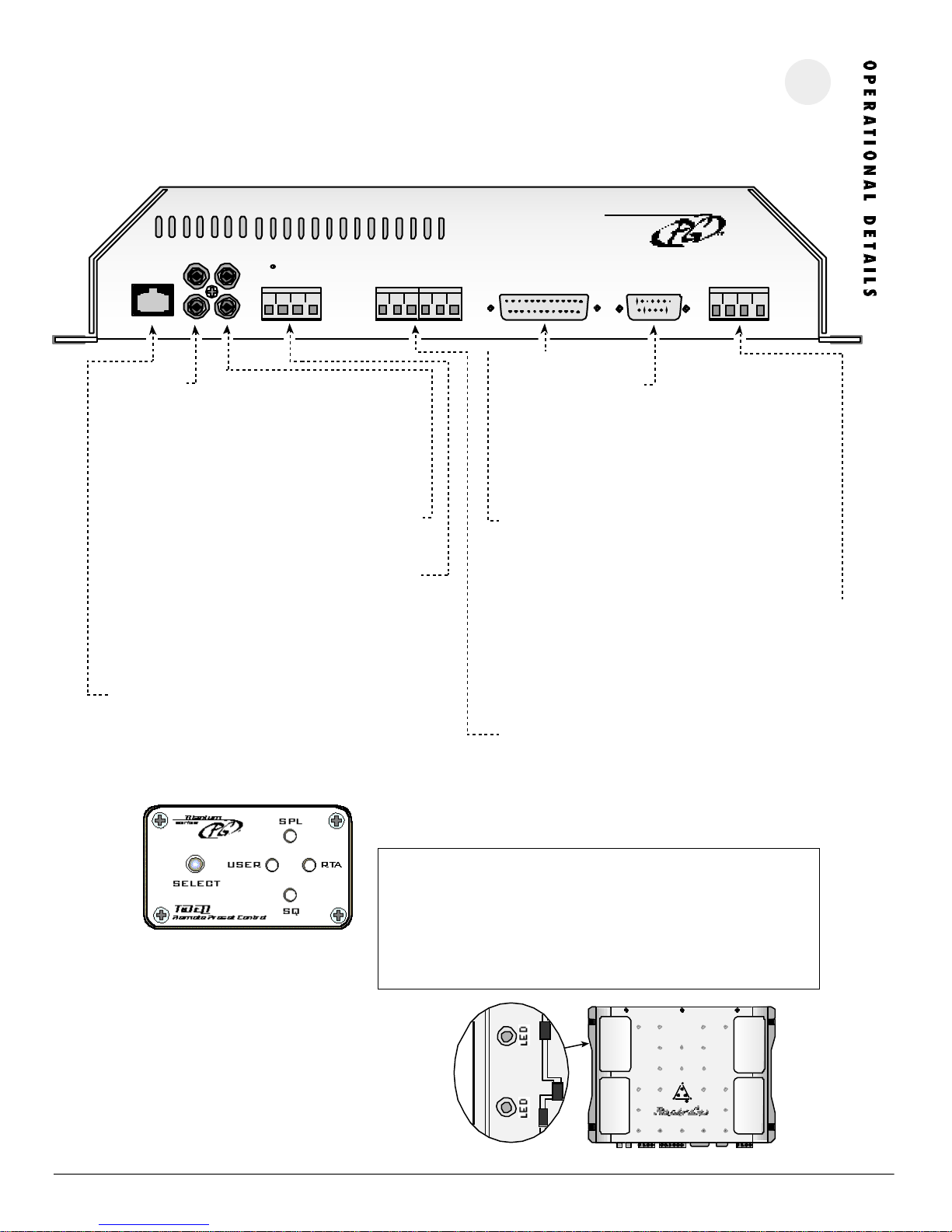
Connect pre-amp signal cables from the headunit to these terminals. To maximize noise rejection, we recommend using Phoenix
Gold ZEROpoint Musical Reference, ZEROpoint Pro, ZEROpoint QLX,
ZEROpoint TRX, XS560 or XS460 series twisted pair interconnects.
Do not use a line driver to drive the inputs of the TiDEQ Comp.
OUT PUTS
Connect pre-amp signal cables to the amplifiers to these terminals
GROU ND TR IGGE R O UT PUTS
Ground will be shown to the preset terminal that is selected on the
TiDEQ Comp. This can be used to trigger relays for multiple applications. For more information see the Ground Trigger Outputs page 5
of the manual.
RE MO TE P RES ET CONTRO L (SEE B ELO W)
This port is for connecting the remote preset control. Pressing the
select button will toggle through the four presets: SPL, SQ, RTA,
USER. Please wait at least 10 seconds after you have changed
presets with the remote before you turn your audio system off.
COM PUTE R P OR T
This port is for connecting the TiDEQ Comp to a computer. The
connection is made via the serial port using a RS232 cable. Please
consult your computer’s hardware setting to configure what COMM
port your computer will be using to communicate with the TiDEQ
Comp.
REM OTE DI SPLA Y PORT
This port is for connecting the optional TiDEQ Comp Remote
Control Unit.
POWE R TERM INA L
B+: Fused +12 volt lead from the battery
B-: Chassis Ground
R: Remote turn-on lead from your headunit
DR: Delayed remote output for turning on other equipment 3
seconds after the TIDEQ COMP turns on.
SENS OR I NP UTS
These inputs are used to display the status of any 12 volt source on
the optional TiDEQ Comp Remote Control. The TiDEQ Comp Remote
and Software must be used in order for the sensor inputs to operate.
The TiDEQ Comp remote control manual illustrates how to use these
inputs.
STA TUS LE Ds
Visible through the window are two dual color LEDs. One for
each channel.
G R E E N : TiDEQ Comp is on and operating normally.
ORANGE: Receiving data from the TiDEQ Comp software or the
output signal of the TiDEQ Comp is being clipped.
I M P O RTA N T I N S TA L L AT I ON N O T E S :
• Do not use a line driver to drive the inputs of the TiDEQ Comp. A line driver is
not needed for the TIDEQ Comp to reach full output.
• Do not mount the TiDEQ Comp to any metal part of the vehicle's chassis this
can cause system noise in some cases.
• Do not plug or unplug the serial port cable or RCA input cables while the TiDEQ
Comp is ON this can damaged the EQ.
P H O E N I X G O L D I N T E R N A T I O N A L
power
i
Page 6
5
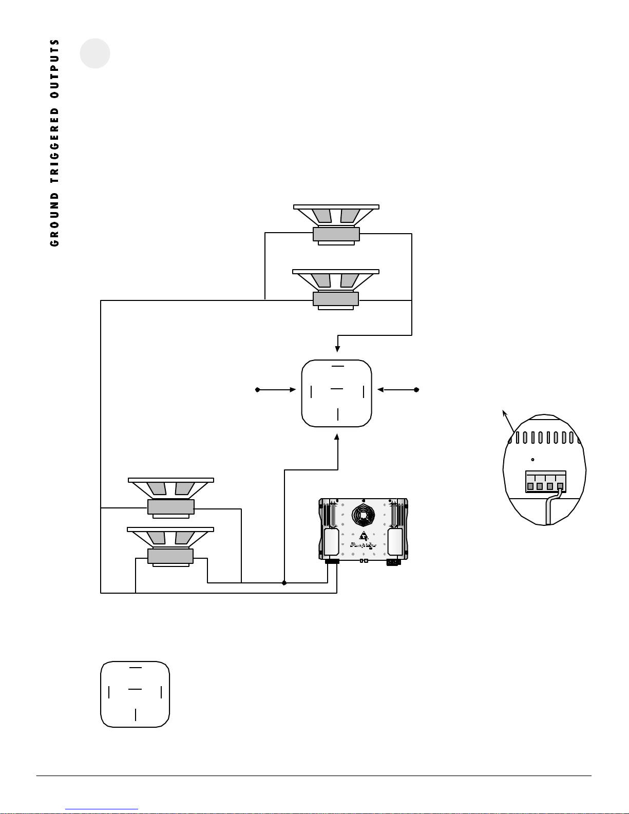
USING GR OUND TR IGG ERE D OUTPU TS
Each time the preset is changed the corresponding output trigger will show ground. This can be used to wire relays that will only trigger when that preset is activated. The following example shows how to turn on extra subwoofers during the SPL portion of a competition. This is just one small example of what the triggered output could be used for. The wiring options are limitless.
In the example below, when the SPL preset is selected the relay will be activated and wire the additional two subwoofers in parallel to the amplifier. When in
preset RTA, USER, or SQ the Titanium 400.2 is wired to two subwoofers in bridged mode using the Left Channel’s Positive (+) and the Right Channel’s Negative
(-). When in the SPL preset the two additional SPL Subwoofers are wired in parallel with the existing two regular subwoofers. Note: All subwoofers in this
example are 8 ohm models.
Pin 85
12 Volt Source
Regular Subwoofers
The two subwoofers below will always play
regardless of the preset selected.
-
+
-
+
Additional SPL Subwoofers
The two subwoofers to the left are extra subwoofers that will be turned on when the SPL
preset is selected.
-
+
+
85
87
86
87a
30
Pin 30
+
Amplifier’s Positive (+) Speaker terminal
Pin 86
SPL’s (-) triggered output
terminal for the TIDEQ.
TRIGGER
OUTPUT
USER SQ RTA SPL
85
87
-
86
+
87a
30
power
Ti
ZX400
-
+
T i 4 0 0 . 2
REL AY PIN AS SIGNME NTS:
Pin 85: 12 Volt Source
Pin 86: TiDEQ’s SPL (-) Triggered Output Terminal
Pin 30: Amplifier’s Positive Speaker Terminal
Pin 87: Speaker’s Positive Speaker Terminal
Pin 87a: Not Used
P H O E N I X G O L D I N T E R N A T I O N A L
Page 7
6
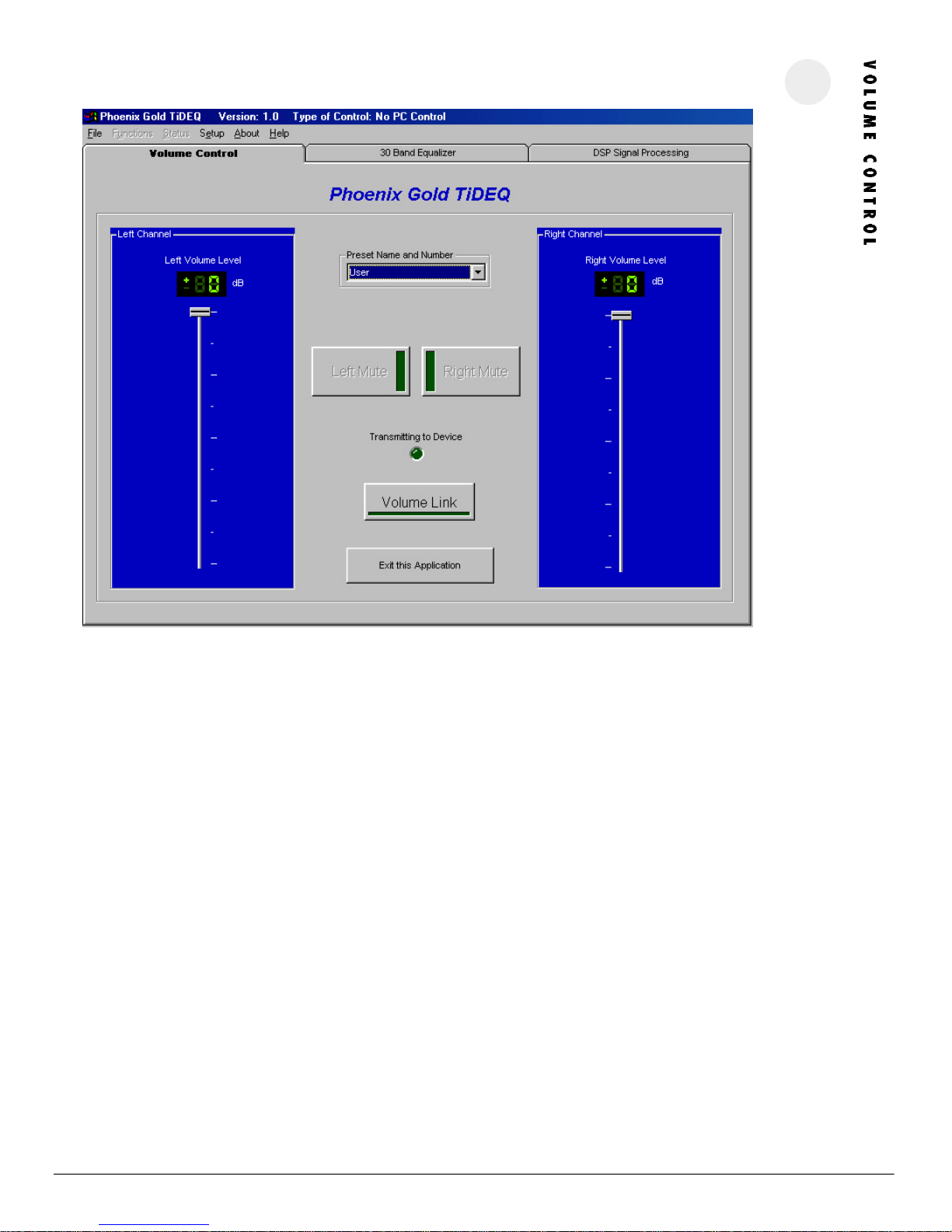
VOLU ME SL IDER S
These are used to adjust the overall levels of the equalizer’s outputs. Both sliders can be moved simultaneously by clicking on the Volume Link
Button. This setting is individually saved for each preset so volume levels can be different for the four separate presets. These sliders will control the
pink noise generator’s volume.
PRES ET NA ME AND NU MBE R
This allows the preset to be changed. There are 4 presets: RTA, SPL, SQ, and USER.
LEFT AND RIGHT MUTE
Clicking on these buttons allows you to mute one or both of the outputs of the TiDEQ Comp. Note that settings for the mute buttons are not saved
for each individual preset. If the a mute button is activated then all four of the presets will be muted, the mute function is not individually saved for
each preset.
VOLU ME LI NK
Clicking on this button allows both left and right channel sliders to be adjusted simultaneously.
EXIT APPL ICAT ION
Clicking on this button will exit and close the TiDEQ Comp program.
P H O E N I X G O L D I N T E R N A T I O N A L
Page 8
7
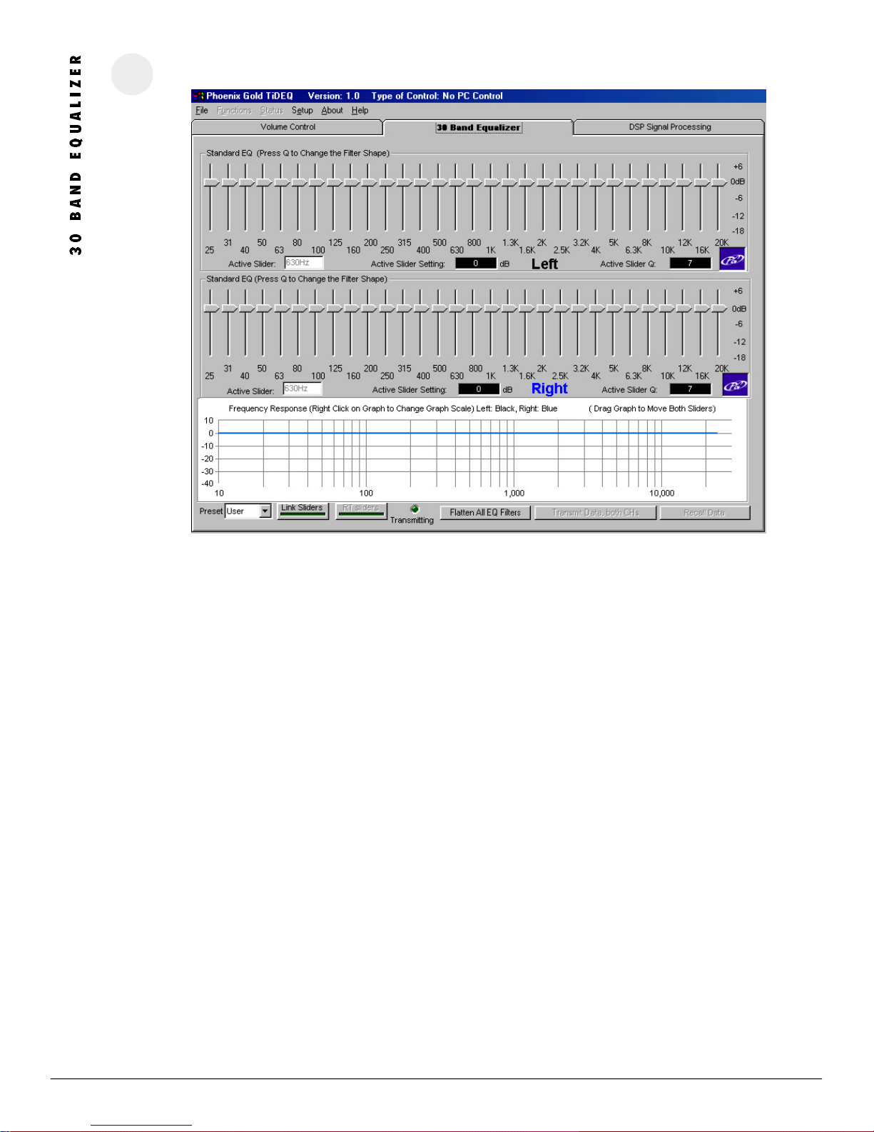
P R E S E T
Allows a different preset to be selected: RTA, SPL, SQ, USER
LINK SLI DERS
This will link the left and right channel sliders, allowing them to be simultaneously adjusted.
RT SLI DERS
Clicking this button activates Real Time Sliders. This allows the changes made on the TiDEQ Comp software sliders to automatically be
sent to the TiDEQ Comp. When activated the TiDEQ Comp in the vehicle will automatically receive the changes made on the screen.
This eliminates the need to click on the “Transmit Data both CHs” button every time you make a small adjustment.
FLAT TEN AL L FILT ERS
Clicking on this button will flatten all slider and parametric filters for the current preset back to 0dB.
TRAN SMIT BOTH CH ANNE LS
Clicking on this button will send all changes for the current preset to the TiDEQ Comp. It will not transmit changes for all 4 presets at
the same time. Changes for each preset must be transmitted individually.
REC ALL DA TA
Clicking on this button will recall the information from the current preset stored in the TiDEQ Comp.
ADJ UST ING SL IDERS
K e y b o a r d : The left and right arrows will change sliders. The up and down arrow keys will also adjust the sliders’ boost/cut value
in 1 dB increments.
M o u s e : Sliders can also be adjusted by clicking and dragging the slider to a new boost/cut value.
R E M I N D E R : If the Real Time Sliders are turned OFF. Changes will not take affect inside the vehicle until you click on the
Transmit Both Channels Button.
P H O E N I X G O L D I N T E R N A T I O N A L
Page 9
8
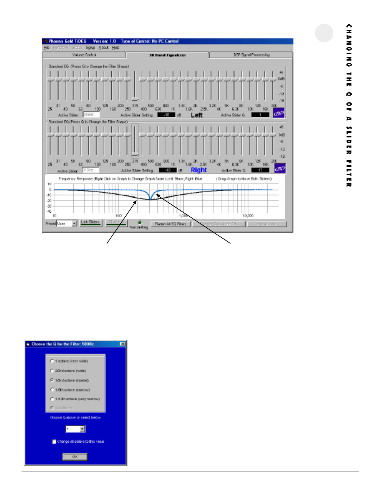
Left: Q=1 Right: Q=17
This feature allows users to change the Q value for any of the sliders on the TiDEQ Comp. Changing this value will affect how narrow or wide of a frequency
range will be affected by the slider’s adjustment.
The example above shows the difference the Q value can make. The 315Hz slider is set to -18dB for both the left and right channels but the graph above
shows a drastic difference in the system response. The black or left channel’s response has a Q value of 1 or very wide. The blue or right channel’s response has
a Q value of 17 or very narrow.
Frequency Slider:
315Hz @ -18dB
ADJU STI NG TH E Q VAL UE
Select a slider by clicking on it then press the “Q” key. The screen to the left will
appear. To adjust the Q of the slider simply select from one of the bullet presets or
pick the specific value from the selection box below. After the value is selected click
the OK button.
To change all 30 sliders’ Q value with one adjustment. Simply check the “Change all
sliders to this value” box. This will change all 30 sliders’ Q value to the selected value.
P H O E N I X G O L D I N T E R N A T I O N A L
Page 10
9
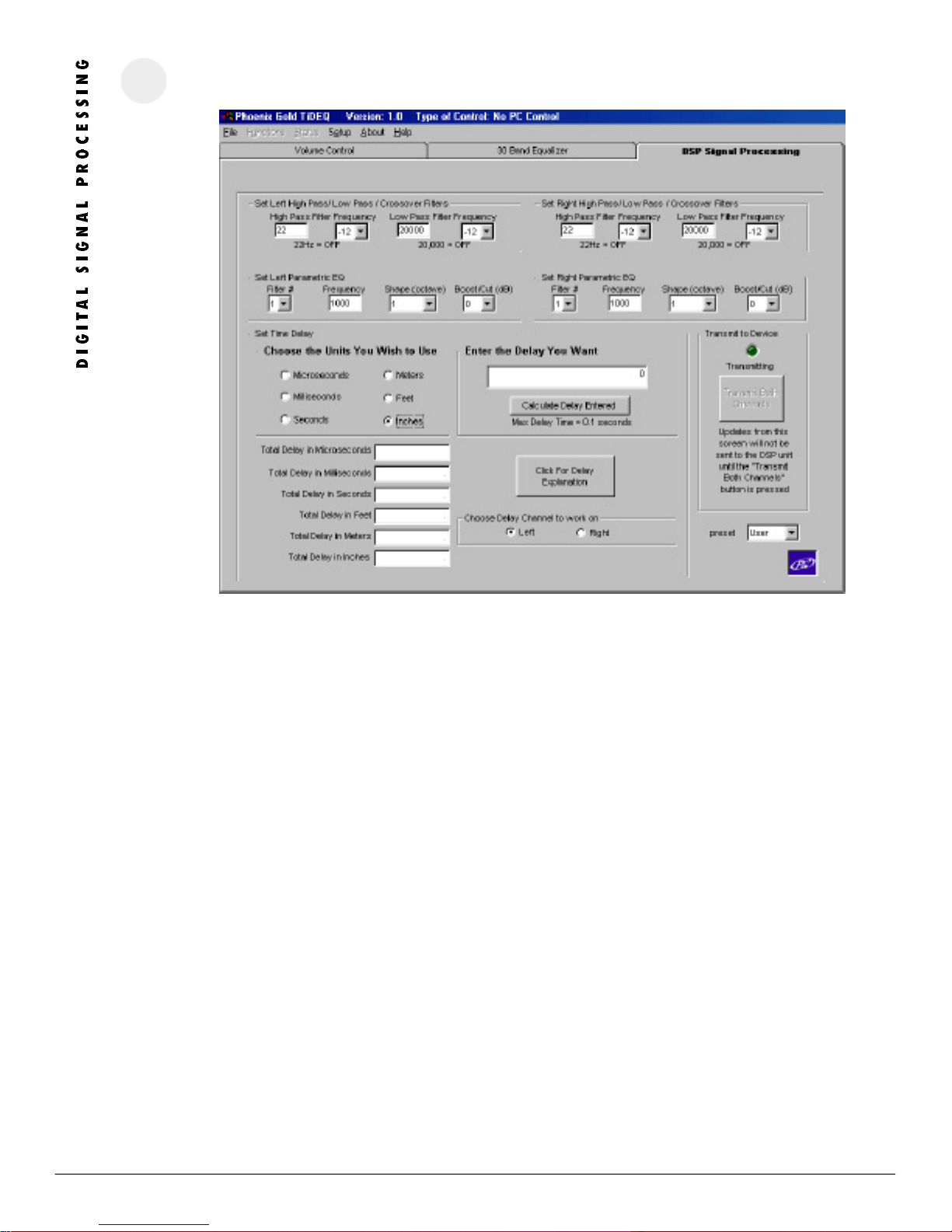
HIGH P ASS FI LTE R F REQU ENC Y
Adjusts the High Pass filter for each channel. Slope is adjustable as 12 or 24db per Octave. Setting the High Pass filter to 22Hz turns the filter off. Type in the
crossover point in the High Pass Frequency Box for each channel.
LOW PA SS FILTER FRE QU ENCY
Adjusts the Low Pass filter for each channel. Slope is adjustable as 12 or 24db per Octave. Setting the Low Pass filter to 20kHz turns the filter off. Type in the
crossover point in the Low Pass Frequency Box for each channel.
PAR AMETRIC EQ
Each channel has 3 parametric filters (6 total) that can be used to alter system response. The center frequency can be between 20Hz to 20kHz. Its Q is
adjustable in 1/3, 1/6, 1/12, or 1/18 octave values. The signal can be changed from a range of +6dB to -18dB. Type in the centered frequency in the
Frequency Box.
DEL AY SET TIN GS
Delay can be set individually for left or right channels in Microseconds, Milliseconds, Seconds, Meters, Feet, or Inches. For an explanation of how to use delay
click on the Delay Explanation button.
TRA NSMIT BOT H CHANN ELS
Clicking on this button will send all changes for the current preset to the TiDEQ Comp. It will not transmit changes for all 4 presets at the same time. Changes
for each preset must be transmitted individually.
R E M I N D E R : Changes will not take affect inside the vehicle until you click on the Transmit Both Channels Button.
P H O E N I X G O L D I N T E R N A T I O N A L
Page 11
TIME DELA Y EXP LANA TION
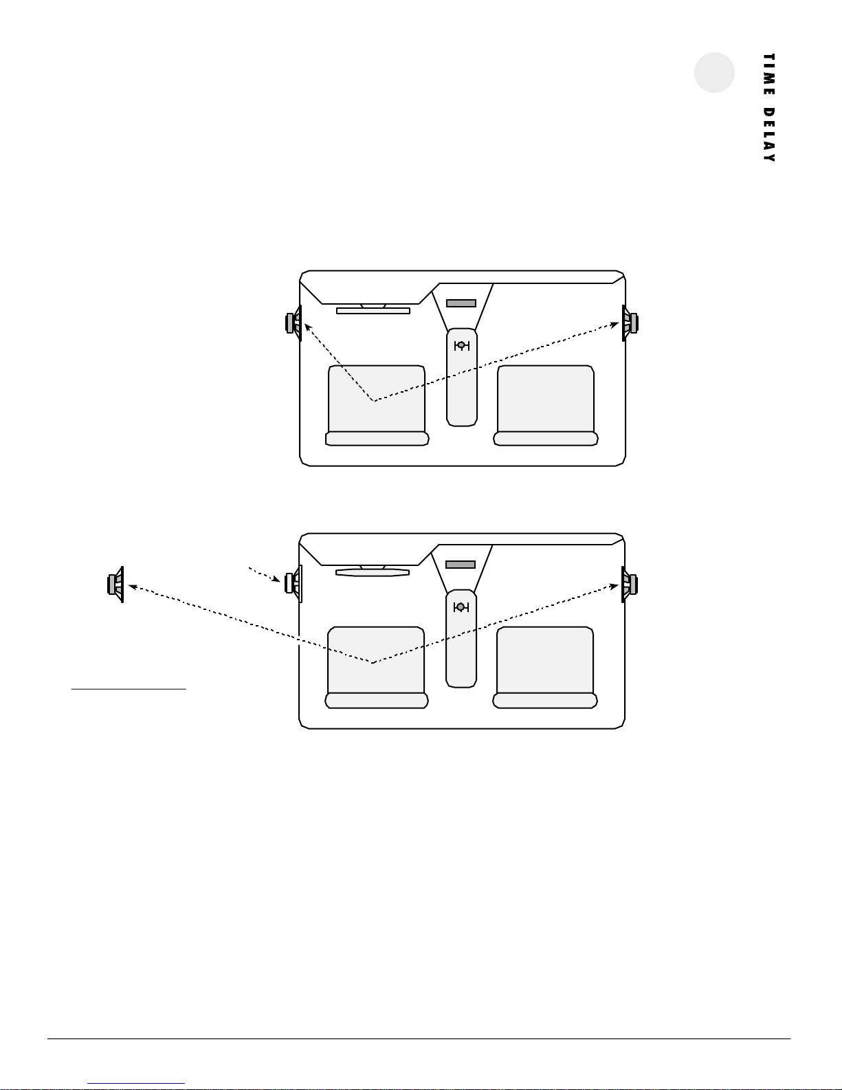
In Figure 1 below, speaker A is located closer to the Driver than speaker B. Naturally information from speaker A will reach the Driver before speaker
B. This unequal pathlength, which is quite common in the car environment, leads to poor sound quality. Time Delay will correct this problem by
allowing the musical information to reach the listener at the proper time without having to relocate the speakers within the vehicle.
By delaying only speaker A we can realign the musical information. For example, delaying speaker A will allow musical information from Speaker A
and B to reach the driver at the same time as it was intended on the original recording. Figure 2 below illustrates this concept.
PAT HLENGTH D IFFERENCE WITHOUT T IME DE LAY . F IGU RE 1.
10
A
Driver Passenger
PER CEIVED PAT HLENGTH D IFF EREN CE WI TH TIME D ELA Y. FIG URE 2.
Perceived Speaker
Location
Actual Speaker
Location
A
44”
Pathlength B = 4 4 ”
Pathlength A = -20”
Total delay needed
for Pathlength A = 24”
Driver Passenger
B
44”20”
B
44”
USIN G TIME D ELA Y W ITH THE TIDE Q SOFT WAR E
Figure 1 above illustrates a 24 inch or 2 feet difference between speaker A and B.
1. Select the “Left” bullet on the Choose Delay Channel.
2. Since we have 2 feet of pathlength difference. Select “Feet” in the unit bullets.
3. Enter “2” into the delay field and transmit your changes.
After the Time Delay changes have taken effect the car will respond similar to what is shown above in Figure 2. Due to unpredictable in car
acoustics minor tweaking with the time delay value is highly recommend to achieve optimal results.
In this example, the driver’s listening position is optimized for sound quality, however, the passenger’s listening position results are unpredictable.
Its nearly impossible to time align both seats at the same time for optimal sound quality. This is important to note because in most competitions
judges will occupy both seats at the same time for sound quality judging.
P H O E N I X G O L D I N T E R N AT I O N A L
Page 12

11
F I L E
RECALL SETTING FROM DISK
Loads a saved project from a storage disk.
SAVE SETTING TO DISK
Quickly saves the project to the disk without changing the Project’s filename.
SAVE SETTINGS TO DISK AS
Saves the project to disk and allows the Project’s filename to be changed.
PRINT PROJECT FILE
Prints project information to a printer.
PRINT GRAPH
Prints project graphics response to a printer.
IMPORT PC RTAJR CURVE
Imports the .dat file from PC RTAjr to the TiDEQ Comp software. The TiDEQ
Comp software will then modify the sliders to the inverse of the PC RTAjr
.dat file, this will create a nearly flat response curve for simple RTA or
Sound Quality tweaking.
C A L E N D E R
Allows the current date to be viewed.
COPY PRESET TO ANOTHER
Allows separate presets to be copied from one to another without manually
changing sliders.
EDIT EXISTING PROJECT
Allows the existing project information to be edited.
E X I T
Exits the TiDEQ Comp program.
UNLOCK DEVICE
“Unlocks” the TiDEQ Comp so changes can be made to the settings.
PINK NOISE GENERATOR
Allows the pink noise generator to be turned ON or OFF for system tuning.
Be sure to adjust your volume settings on the TIDEQ COMP before turning
on.
S T A T U S
UPDATE DEVICE STATUS
Checks if the TiDEQ Comp is muted and or locked.
CHECK HARDWARE AND FIRMWARE VERSIONS
Displays the Hardware and Firmware versions on the TiDEQ Comp.
S E T U P
SETUP RS232 COMM PORT
Selects which of the computer’s COMM ports will be connected to the
TiDEQ Comp.
TURN RS232 ON/OFF
DEMO MODE
This allows projects to be changed and saved without being connected to
the TiDEQ Comp. When finished working in Demo Mode you must transmit
the changes to the TiDEQ Comp in PC Serial Mode for the changes to take
effect in the vehicle.
PC SERIAL PORT
The computer and TiDEQ Comp are connected together with a serial cable
via the COMM port. This is the only mode in which changes can be transmitted from the TiDEQ Comp software to the TiDEQ Comp unit.
FACTORY CALIBRATION
For special use only by Phoenix Gold Factory Members.
F U N C T I O N
TRANSMIT DATA TO DEVICE
Sends data from TiDEQ Comp software to the TiDEQ Comp.
RECALL DATA FROM DEVICE
Recalls the last stored data from the TiDEQ Comp to the TiDEQ Comp software.
MUTE ALL CHANNELS
Mutes the left and right channels of the TiDEQ Comp.
UNMUTE ALL CHANNELS
Disables the muting of the left and right channels of the TiDEQ Comp.
LOCK DEVICE TO DISABLE UNAUTHORIZED TAMPERING
Allows the TiDEQ Comp to be “locked” so settings are not able to be
changed.
A B O U T
PROJECT COMMENTS
Displays the current project’s comments.
ABOUT SOFTWARE
Presents the TIDEQ COMP software version number and information.
H E L P
Displays the TIDEQ COMP help file.
P H O E N I X G O L D I N T E R N A T I O N A L
Page 13
IMP ORTING A PC RT Aj r F I L E
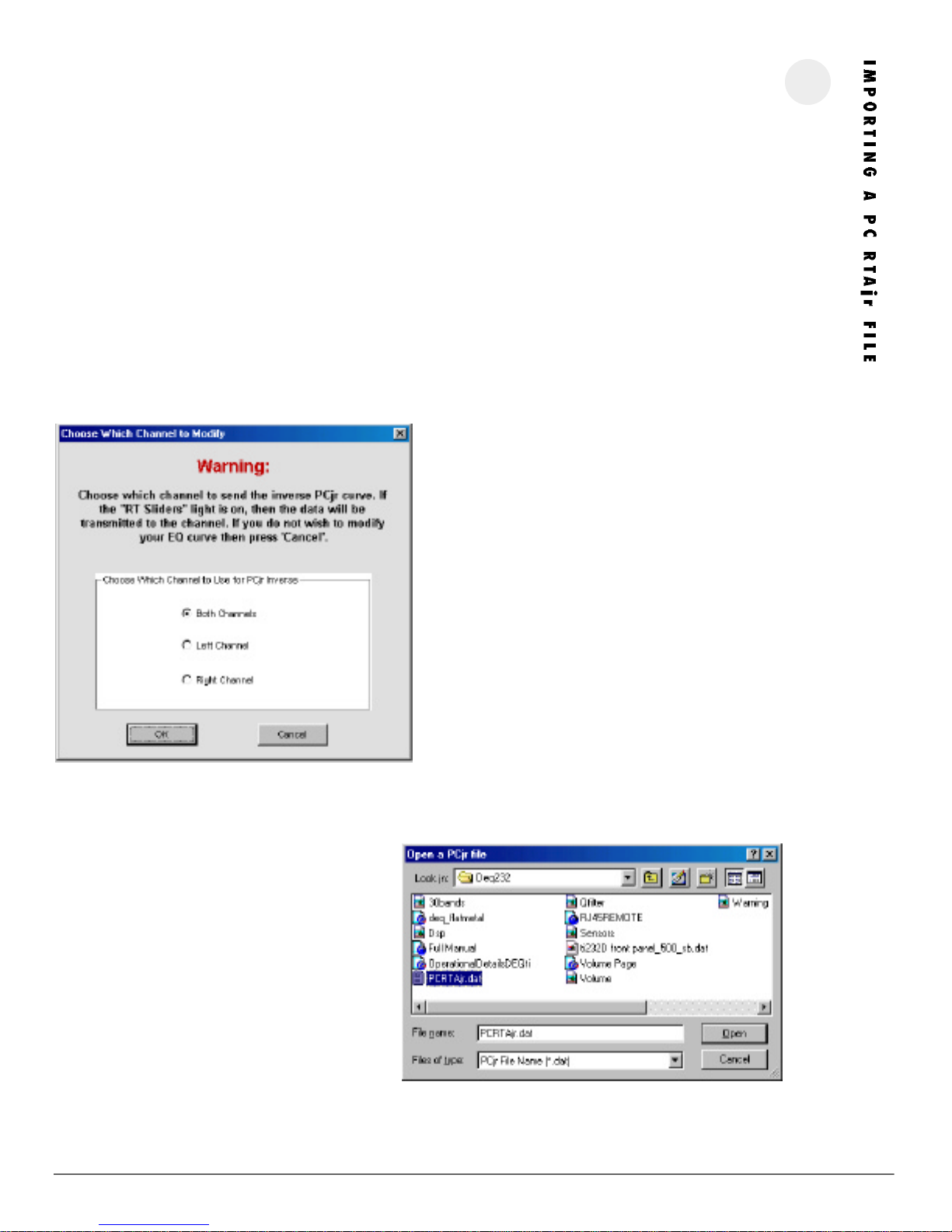
This feature allows users to import data files from Linear X’s PC RTAjr software. Importing this data allows the TiDEQ Comp software to automatically modify
the TiDEQ’s sliders to the inverse of the PC RTAjr data file. The TiDEQ Comp software will then automatically adjust the sliders so the system’s response with
flatten with a click of a button. Keep in mind, the curve will not be perfectly flat in most cases due to in car variances. The purpose of this feature is to provide
an excellent basis to begin tweaking for Sound Quality or RTA portions of competitions.
If only one serial port is present on the computer then the TIDEQ COMP software and PC RTAjr must be run at separate times. If two serial ports are present
then you can measure the car’s response with PC RTAjr and adjust the car’s response with the TiDEQ Comp at the same time since they will be connected via
two separate
serials ports.
I N S T R U C T I O N S :
Open the PC RTAjr software. Place the microphone in the car and run pink noise through the system. Adjust the PC RTAjr software so the system’s response is
visible on the PC RTAjr software. Now save the current response shown on the screen as a (filename).dat file. In this example the file is called PC RTAjr.dat.
Turn off the car’s audio system and connect the computer’s serial port
to the TiDEQ Comp if its not already connected.
12
Next select where the PC RTAjr.dat PC RTAjr file is located on your
computer. Select the directory where the file is saved. If the file is not
visible type *.* in the file name text box and hit enter . This will show all
files stored in the directory, instead of just the files ending in .dat.
After the file has been selected, then click “Open”. It will take a few
seconds and then the sliders will adjust according to the information on
the PC RTAjr file.
Turn on the car’s audio system. Open the TiDEQ Comp software. Goto the
30 Band Tab and turn Real Time Sliders OFF. Make sure all sliders’ Q
value is set to the default value: 7. See page 8 for more information
how to do this.
Goto File and select Import PC RTAjr Curve. A window will open giving
the option of the changes to be made to both, left, or right channels.
Transmit your changes to the TiDEQ Comp, so they will take effect in the
car. In most cases, in car acoustics will cause slight variations in the frequency response. However, making adjustments to the sliders and/or the
additional bands of paramentric equialization will allow the curve to be
flatten even further.
P H O E N I X G O L D I N T E R N AT I O N A L
Page 14

13
P R O B L E M :
PO SSIBLE CAU S E:
S O L U T I O N :
No output and Power-on LED is off
No output and Power-on LED is on
Distorted sound
No battery, ground, or remote connection
Blown power fuse
No signal from the headunit
Faulty input signal cables
Clipped input signal feeding the amplifier
Connect B+, B-, and a remote turn-on to
the TiDEQ Comp. The TiDEQ Comp must
have clean solid chassis ground connected
to the B- terminal and receive at least 11
volts through the B+ and remote turn-on
terminals.
Use an ohm meter to check for a short to
chassis ground in the B+ cable with the
B+ cable disconnected from the TiDEQ
Comp, battery and all other devices. Send
the unit to an authorized Phoenix Gold
Repair Center for repair, do not replace
the blown fuse in the field.
Use an AC volt meter to check for voltage
at the headunit's preamp outputs. The
level should fluctuate with the peaks in
music.
Make sure the headunit is not producing a
clipped signal. Most headunits clip their
own output above 7/8 volume. Distorted
signals coming into the TiDEQ Comp will
sound distorted at any input sensitivity
setting. Do not use a line driver to drive
the inputs of the TiDEQ Comp.
Changes from TiDEQ Comp software don’t
take effect in car
Can’t find the PC RTAjr file to import
Sensored inputs won’t work
Changes have not been transmitted
File may be named different
File may be in different directory
TiDEQ Comp Software and Optional
Remote Control are not being used
P H O E N I X G O L D I N T E R N A T I O N A L
Click on the transmit changes button on
the DSP or 30 band software tabs.
Type *.* and hit enter in the file name
text box. This will show all files stored in
the directory, instead of just the files ending in .dat.
TiDEQ Comp Software and Remote Control
must be installed together to in order for
the sensored inputs to operate
Page 15

WAR RANTY INF OR MATI ON
Phoenix Gold International, Inc. (or "Phoenix Gold") warrants its products against defects in materials and workmanship for a limited period of time.
For a period of one (1) year from date of original purchase, we will repair or replace the electronic product, at our option, without charge for parts
and labor. The limited warranty period is EXTENDED to three (3) years from date of original purchase if the product was originally installed by an
authorized Phoenix Gold electronics dealer and accompanied by a valid sales receipt showing a charge for installation. Customer must pay all parts
and labor charges after the limited warranty period expires. The limited warranty period for factory refurbished products expires after ninety (90)
days from date of original purchase. This limited warranty applies only to purchases from authorized Phoenix Gold Electronics and Speaker retailers.
This limited warranty is extended only to the original purchaser and is valid only to consumers in the United States. Consumers are required to
provide a copy of the original sales invoice from an authorized Phoenix Gold dealer when making a claim against this limited warranty. This limited
warranty only covers failures due to defects in materials or workmanship that occur during normal use. It does not cover failures resulting from
accident, misuse, abuse, neglect, mishandling, misapplication, alteration, faulty installation, modification, service by anyone other than Phoenix
Gold, or damage that is attributable to Acts of God. It does not cover costs of transportation to Phoenix Gold or damage in transit.
This warranty will become void if the serial number identification has been wholly or partially removed, altered or erased. Repair or replacement
under the terms of this warranty does not extend the terms of this warranty.
Should a product prove to be defective in workmanship or material, the consumer's sole remedies will be repair or replacement as provided under
the terms of this warranty. Under no circumstances shall Phoenix Gold be liable for loss or damage, direct, consequential or incidental, arising out of
the use of or inability to use the product. There are no express warranties other than described above.
P H O E N I X G O L D I N T E R N AT I O N A L
Page 16

Phoenix Gold International, I n c .
9300 North Decatur
Portland,Oregon 97203
tel: 503.286.9300
fax:503.978.3380
www.phoenixgold.com
In Canada:
Trends Electronics
#100 980 West 1st Street
North Vancouver, British Columbia
Canada V7P 3N4
tel:604.988.2966
fax:604.988.4122
www.trendsinc.com
In Europe:
Phoenix Gold Europe
Ter Heidelaan 50A
3200 Aarschot
Belgium
tel:32.16.553.553
fax:32.16.553.559
email:[email protected]
8100.0193A
 Loading...